1. Introduction
Fully ceramic microencapsulated (FCM) fuel isformed by tristructural isotropic (TRISO) fuel particles embedding in SiC matrix [
1]. FCM is both an acronym and trademark of a patented technology and is written as FCM
TM in this paper. The TRISO particle was constituted of fuel kernel and four coated layers including the low-density carbon buffer layer, the inner and outer pyroltytic graphite layers which surround the silicon carbide (SiC) micropressure vessel. The function of the coated layers and SiC matrix has been discussed [
2,
3]: the buffer layer offered the space to accommodate the generated fission production; the inner and outer pyroltytic graphite layers are the protective layers which can decrease the stress of SiC layer and protect the SiC shell from the energetic fission product recoil damage. SiC layer is the main structural layer which can prevent fission gas release. The functional coated layers and dense SiC matrix of FCM
TM offered excellent oxidation resistance and fission product capability, high thermal conductivity and irradiation stability [
4,
5]. FCM
TM pellets are contained by zircaloy cladding for using in light water reactors (LWR) and small modular reactors (SMRs) [
6,
7].
Obvious safety characteristics, including lower operation temperature and radionuclide production release, can be obtained by using FCM
TM fuel [
3]. However, FCMs with UO
2 or UCO kernel possessed lower fissile loading compared with the UO
2 pellet, which cannot satisfy loading requirement of reactor core and limit the application of FCM
TM fuel [
8]. UN kernels are currently under investigation to increase the fissile loading [
8,
9]. TRISO particle with high uranium dense has been fabricated in order to increase the uranium loading. U-C-N was used as TRISO kernel to avoid the reaction between the kernel and the buffer layer [
10,
11]. The performance of TRISO particles with UN kernel has been investigated in previous reports [
12,
13].
Feasibility and fuel cycle cost of the FCM
TM pellet used in different kinds of reactors has been investigated, such as light water reactor, high-temperature gas-cooled reactor, and small pressurized water reactor [
14,
15]. An FCM
TM pellet can meet the requirements of different kinds of reactors and increase the safety of the reactors, however, application of FCM
TM may increase fuel cycle costs. The report on thermal–mechanical performance simulation of FCM
TM pellet was rare because of the complex structure, contacting behavior and material properties. The behavior of TRISO particle has been studied vastly and lots of software such as PARFUM, PASTA and STRESS3 has been developed [
16]. The performance of TRISO particle can be used as input parameters for the FCMTMsimulation including internal pressure and size deformation [
17,
18]. The performance of TRISO-based FCMTMfuel in LWR environment was simulated by Schappel and co-workes using BISON [
18]. UN was used as TRISO particle kernel to increase the fissile loading of FCMTM. The properties of UN kernel and coated layers were considered including thermal conductivity, swelling and creep of pyrolytic carbon (PyC), thermal conductivity and swelling of chemical vapor deposition (CVD) and nano-infiltration and transient eutectic (NITE) SiC. The simulated results of TRISO particle which calculated by BISON and PARFUM code were compared. The interaction between particles with different distance was calculated but only half of five particles were reserved in the pellet. FCMTMperformance was calculated by subtracting out of TRISO particles and the maximum temperature and hoop stress of SiC matrix was studied. The performance of coated layers was not detected and the interaction between TRISO particle and matrix was not reflected in the literature. Effect of SiC matrix on the performance of TRISO particle was investigated by Ougouag and co-worker [
19]. A two-dimensional model was established by adding SiC matrix on the single TRISO particle, the result indicated that the thickness of SiC matrix can affect the stress distribution of the coated layers and SiC matrix. Stress and temperature distribution of the SiC matrix among different TRISO particles was not discussed. The thermal-mechanical performance and criterion to evaluate the integrity of the FCM
TM pellet was discussed in our previous work for the given structure, the effect of FCM
TM structure such as TRISO particle distance and non-fuel part size on the thermal-mechanical performance was not studied [
16].
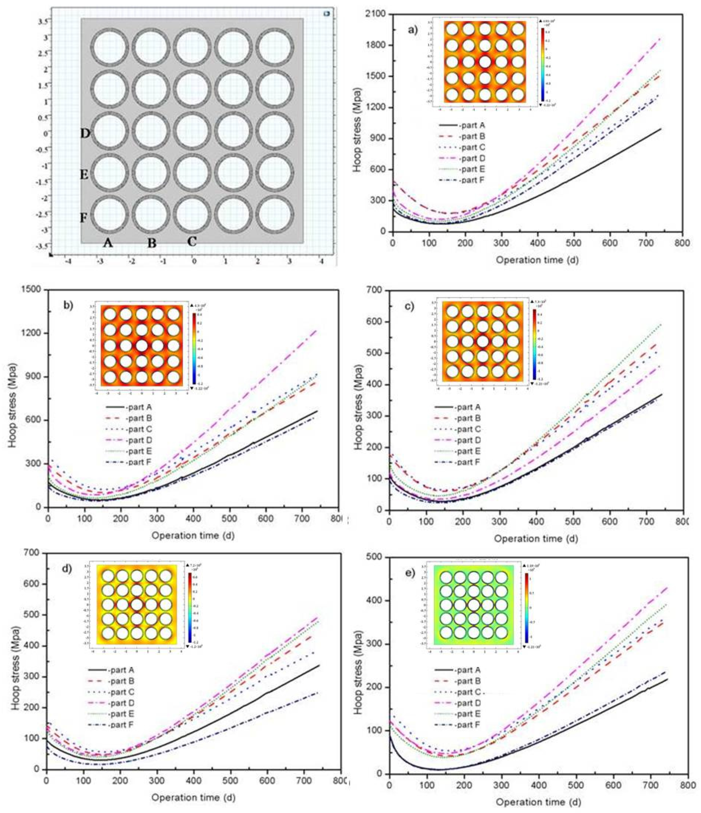
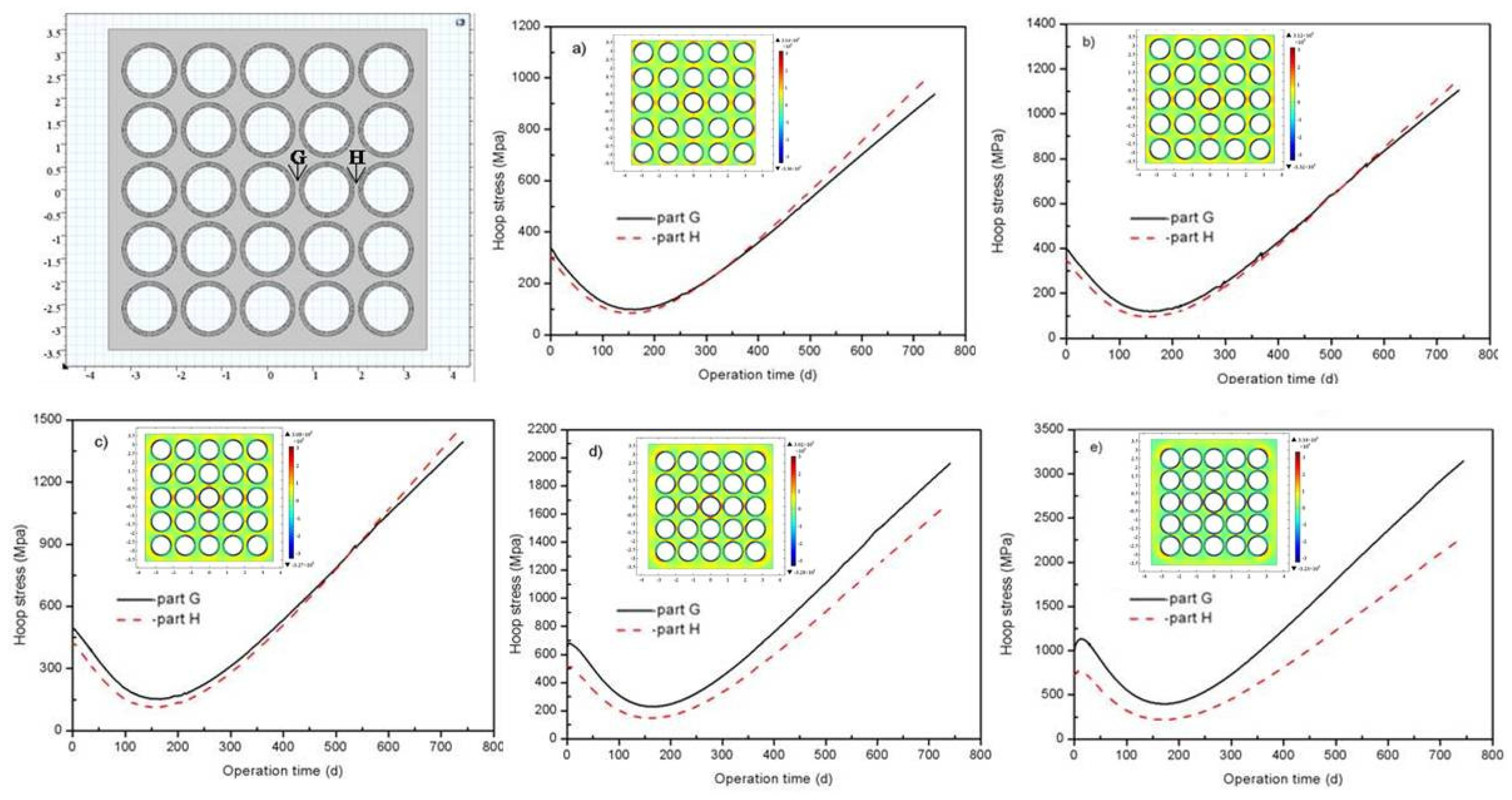
In this paper, the effect of structure on the FCMTM performance was studied for the given TRISO particle fraction (40 vol%), and the structure was optimized to decrease stress and failure probability of SiC layer and non-fuel part. The performance of the FCMTM pellet with different non-fuel part size was simulated by using two-dimensional model. The internal pressure and size variation of TRISO particles was calculated by using 1/8 characteristic unit, and the results was used as input parameters for FCMTM simulation. The effect of FCMTM structure on the maximum temperature and hoop stress of SiC matrix was studied.
2. Materials
Five different kinds of materials were used in FCMTM pellet in this paper, including Uranium Nitride (UN), porous carbon buffer (buffer layer), dense pyrolytic carbon (PyC layer), chemical vapor deposition SiC (SiC layer), and sintered SiC matrix material (SiC matrix). The properties of the coated layers and SiC matrix have great effect on the performance of the FCMTM pellet. UN was chosen as kernel to increase the uranium loading of reactor core. UN has excellent compatibility with buffer layer and no reaction was occurred between kernel and carbon, which can decrease the internal pressure obviously [
20]. The buffer layer offered the space for accommodating the fission production because of the high porosity of buffer layer. The UN kernel and buffer layer weresubtracted out when simulate the FCM
TM pellet behavior because the gap appeared, and no interaction occurred between the buffer layer and the other coated layers [
17,
18]. Inner and outer PyC layers are designed to provide mechanically pliable layers supporting the SiC micro-pressure vessel [
17]. SiC matrix and layer in TRISO particles are expected to offer improved containment of fission production under accident condition. At the same time, SiC matrix possessed higher thermal conductivity compared with UO
2, which can decrease the operation temperature obviously for comparative rod average linear power [
18].
2.1. Uranium Nitride
Thermal conductivity of UN (
KUN) is the function of burn-up (
Bu), temperature (
T) and porosity (
p) [
21]. The thermal expansion coefficient (
αUN) and specific heat (
Cp,UN) are the functions of temperature (
T). The relative properties can be expressed by the following equations [
21]:
The irradiation swelling of UN kernel was measured in space reactor; the swelling rate of UN kernel had great influence on the dimensional change of coated layers [
13]. UN kernel swelling was given by
where Δ
V and
V are the volume increment (%) caused by irradiation and the initial volume respectively.
T is the temperature (K),
Bu is the burnup (MW∙d/TU), and
ρ is the density of UN kernel (kg/m
3).
Fission gas (Xe, Kr, and He) release was calculated according to two mechanisms: the recoil release and diffusion release. The release of Xe and Kr was controlled by the two mechanisms but the release of He will be only considered coming from diffusion release mechanism [
22]. The recoil release will be the predominant mechanism at low temperature and its portion of fission gas can be calculated from the following empirical equation [
8]:
where
f is the portion of Xe and Kr,
S is the superficial area of fuel particle (m
2),
V is the volume of fuel particle (m
3), and
α is the mean recoil range of fission gas atoms (m). The mean recoil range of Xe and Kr is 3.98 μm and 5.68 μm, respectively [
22].
The main mechanism of fission gas release at high temperature is diffusion release, and the Booth classical diffusion model was employed in this study to compute the final release fission gas of loose pyrolytic carbon and the gap through diffusion mechanism. The grain of UN was considered as the ideal sphere of 20 μm in diameter, which means the solving equation can be simplified as 1-dimensional form. The effective diffusion coefficient of fission gas atoms within the fuel grains can be set from the following empirical relation [
22]:
where
Dg is the effective diffusion coefficient of fission gas atoms within the fuel grains.
2.2. Buffer Layer
The density of buffer was about 0.9–1.0 g/cm
3. Buffer layer is expected to isotropically shrink under irradiation condition, and the gap appeared due to the shrinkage of buffer layer. Internal pressure can be decreased by increasing the thickness of buffer layer. Porosity has great influence on the thermal conductivity of buffer layer. The thermal conductivity of buffer layer can be written as follows [
22]:
where
P is the porosity of buffer layer (%). The thermal conductivity of buffer layer increased with neutron fluence due to the densification of buffer layer [
18].
The elastic modulus of the buffer layer is isotropic, the expression can be written as follows [
22]:
where Φ is the fast neutron flux (10
25n·m
−2) and T is temperature (K).
2.3. PyCLayer
High density pyrolytic carbon was used as IPyC and OPyC layers to protect SiC layer from fission production corrosion and matrix defects. The desity of IPyC and OPyC layers are about 1.9–2.1 g/cm
3. PyC layers are expected to shrink initially and then the radial direction is expected to expand while the tangential direction is expected to continue shrinking when the neutron fluence reached 2 × 10
25 n/m
2. The radial and tangential irradiation strain of PyC layers are expressed by the following equations [
22].
where
and
are the radial and tangential irradiation strain (%), Φ is the fast neutron flux (10
25n·m
−2).
Elastic modulus of the PyC layer is anisotropic and can be calculated by the following equation [
22]:
where Φ is the neutron flux (×10
25 n/m
2), and T is the temperature (K), BAF is the anisotropic parameters of PyC.
PyC and buffer layers exhibit same creep strain, the expression was given by the following equation [
21]:
where
is the fast neutron flux rate (10
25n·m
−2·s
−1),
vc is the Poisson ratio, and
Kpyc is the creep constant (n∙m
−2∙s
−1).The expression was given by
where
ρ0 is the initial density (g/cm
3).
K0 is the function of temperature, and the expression was written as
where
T is the temperature (K).
2.4. Silicon Carbide
Silicon carbide experiences irradiation-induced swelling at all temperatures, but the swelling mechanism of SiC is different at different temperatures. The point defects swelling may be the dominant mechanism at relative low temperature. At higher temperature (1173–1673 K), Frank faulted loops of interstitial type was the dominant defects, and the Frank faulted loops appear for temperature neutron irradiation at extremely high doses. The irradiation swelling was the function of temperature and neutron flux [
23]. The thermal conductivity was modeled as the function of volume swelling and temperature.
The swelling model of the SiC is the function of temperature and neutron flux, which can be written as follows [
23]:
where
S is the swelling rate (s
−1);
ks is the coefficient of the swelling rate (dpa
−2/3);
γ is the neutron flux (dpa);
γsc is the characteristic dose for swelling saturation by the negative feedback mechanism (dpa). The swelling of SiC can be obtained from the time integration of the Equation (15).
where,
Ss and
γsc are the function of the temperature, and can be expressed as below:
The thermal conductivity model of SiC layer was expressed [
17] as
where
R0 and
Rirr are the thermal resistance (K/W) of the prior- and post-irradiated SiC layer, respectively.
The thermal resistance of SiC layer before irradiation is expressed as below [
17]:
The thermal resistance induced by the irradiation can be written [
17] as
where
S is the volume swelling (%).
Thermal conductivity of SiC matrix can be expressed by multiplying a parameter on the thermal conductivity expression of SiC layer because the thermal conductivity exhibited similar variation trend and the value was different between SiC matrix and layer [
24]. The parameter was defined as 0.75.
The specific heat, elastic modulus and elastic Poisson Ratio of SiC was set as constant, the values are 1200 J∙kg
−1∙K
−1, 450 GPa, and 0.2 respectively [
23].
The creep model of SiC can be expressed as follows:
where K
1 is a temperature-dependent creep coefficient, the value of K
1 was 0.4×10
−31 n/(m
2∙MPa),
is the neutron flux in n/(m
2∙s), and
is the effective stress.
Failure probability of the SiC layer was calculated according to the strength and stress distribution of FCM
TM pellet. The failure probability of SiC layer can be calculated by the following equation [
23]:
where
V is the characteristic volume (m
3),
m is the Weibull modulus of SiC layer,
σ0 is the characteristic strength (MPa), and
σp is the true stress (MPa). The characteristic strength and the Weibull modulus ofSiC layer were 350MPa and five, respectively [
17].
3. Geometry Parameters and Modeling Approach
The kernel diameter was 800 μm which was larger than the traditional TRISO particle (about 450 μm) to increase the fissile loading in order to meet the requirement of LWR. The thickness of the coated layers was designed, the thickness of buffer, IPyC, SiC, and OPyC layers were 100 μm, 30 μm, 40 μm, and 30 μm, respectively.
A FCM
TM pellet with 40vol% TRISO particle loading was simulated. FCM
TM pellets with different non-fuel part size were design, and the effect non-fuel part size on the performance of FCM
TM was investigated. FCM
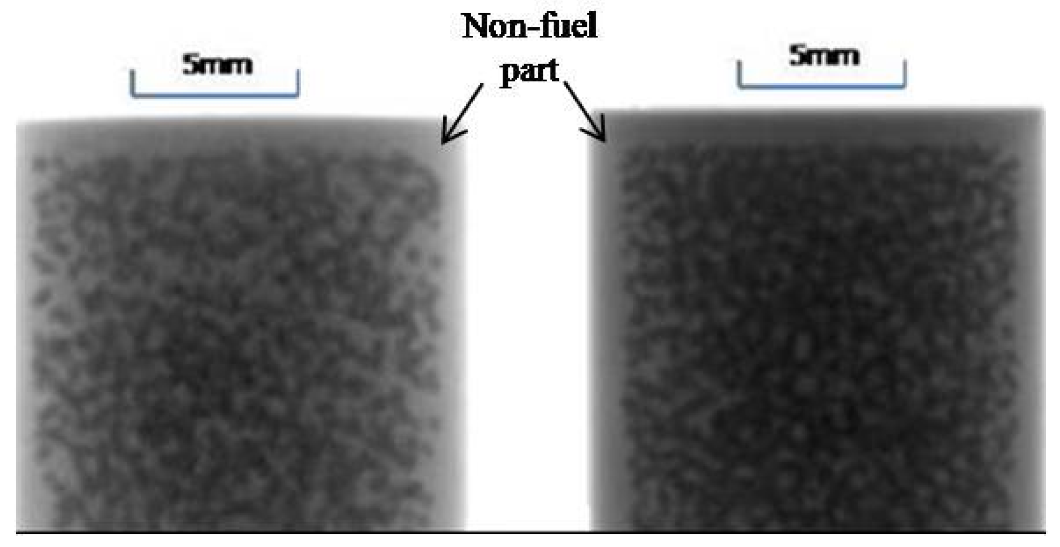
TM pellet with non-fuel part has been fabricated by our group, the microstructure was obtained by using X-ray imaging techniques as shown in
Figure 1. The irradiation measurement will be conducted in the future in our own testing reactor. The definition of a non-fuel part isshown in
Figure 1. The distance between two TRISO particles decreased with the increasing of non-fuel part size due to the certain TRISO particle loading in FCM
TM pellet. The FCM
TM pellet samples with different non-fuel part size were labeled. For example, N100 means the non-fuel pare size of the sample was 100 μm.
The temperature and stress distribution in FCM
TM and TRISO fuel was calculated using heat transfer and the solid mechanical model, respectively, which was offered by COMSOL multi-physics software (COMSOL-5.2, MERCURY LEARNING AND INFORMATION LLC, Dulles, Virginia). The heat conduction equation and heat flux used to calculate the FCMTM performance have been introduced in our previous work [
17]. The fission gas release was calculated according to two mechanisms including the recoil release and diffusion release. The model of the fission gas release was discussed in above section. The internal pressure was calculated according to the ideal gas low, the temperature, amount of fission gas, and gap volume, which were investigated using the TRISO particle model.
The schematic of the calculation flow used COMSOL-5.2 software, as shown in
Figure 2. Here, a 1/8 sphere unit was used to simulate the performance of TRISO particle, the internal pressure under different temperatures were calculated as input parameters for FCM
TM simulation. Two-dimensional models of FCM
TM pellet with different structure parameters were established. Solid mechanics and heat transfer modules were selected for normal condition. Materials property models were input by defining the analytic functions. The boundary condition of TRISO particle and FCM
TM pellet was defined, symmetry boundary condition and surface temperature were defined for the three sides and surface of TRISO particle respectively. The boundary conditions of FCM
TM pellet have been introduced in our previous work [
17]. The temperature field, stress distribution and failure probability were output and the structure of FCM
TM pellet was optimized.


