Article

The Application of Indium Oxide@CPM-5-C-600 Composite Material Derived from MOF in Cathode Material of Lithium Sulfur Batteries

Shanxi Key Laboratory of Nanomaterials & Nanotechnology, School of Mechanical & Electrical Engineering, Xi’an University of Architecture & Technology, Xi’an 710055, China
*
Author to whom correspondence should be addressed.
Nanomaterials 2020, 10(1), 177; https://doi.org/10.3390/nano10010177
Submission received: 7 December 2019 / Revised: 5 January 2020 / Accepted: 9 January 2020 / Published: 20 January 2020

Abstract

:
Due to the “shuttle effect”, the cycle performance of lithium sulfur (Li-S) battery is poor and the capacity decays rapidly. Replacing lithium-ion battery is the maximum problem to be overcome. In order to solve this problem, we use a cage like microporous MOF(CPM-5) as a carbon source, which is carbonized at high temperature to get a micro-mesoporous carbon composite material. In addition, indium oxide particles formed during carbonization are deposited on CPM-5 structure, forming a simple core-shell structure CPM-5-C-600. When it is used as the cathode of Li-S battery, the small molecule sulfide can be confined in the micropores, while the existence of large pore size mesopores can provide a channel for the transmission of lithium ions, so as to improve the conductivity of the material and the rate performance of the battery. After 100 cycles, the specific capacity of the battery can be still maintained at 650 mA h·g−1 and the Coulombic efficiency is close to 100%. When the rate goes up to 2 C, the first discharge capacity not only can reach 1400 mA h·g−1, but also still provides 500 mA h·g−1 after 200 cycles, showing excellent rate performance.

1. Introduction

With the increasing demand for electric vehicles and high scale-energy storage, searching for the high-performance energy storage materials has become a new focus [1,2]. Lithium-ion (Li+) batteries have become an indispensable part of various electronic products because of high voltage and good stability [3,4,5,6,7,8,9]. However, the Li+ battery has such problems as low capacity and poor safety, which greatly limits its application. Therefore, the next generation battery, Lithium-sulfur (Li-S) battery, which incorporate abundant active sulfur as cathode materials, has drawn extensive research as one of the most promising candidates for next generation energy storage system. Owing to the high theoretical specific capacity of 1675 mA h·g−1 (fourfold higher than the conventional state-of-the-art LIBs) and energy density of 2600 Wh kg−1 [10], it can replace Li+ battery. However, although sulfur has many advantages, such as low cost, abundant natural resources and low toxicity, several issues need to be solved for sulfur as a cathode for practical application of Li-S battery. First, during the process of charging and discharging, Li-S batteries have a large volume expansion, and it is easy to cause damage to the structure of the negative electrode material during the cycle; Second, the poor electronic conductivity of element S (5 × 10⁻³⁰ cm−1 at 25 °C) can affect the conductivity of materials and the rate performance of batteries; Third, During the cycle, the production of Li2S and Li2S2 will coat the surface of the active material, thereby preventing Li+ from entering the electrode; Fourth, the intermediate products (polysulfides) of the reaction easily dissolve in the electrolyte, which will cause severe capacity decay, resulting in a serious “shuttle effect” [11,12,13,14].
In order to solve these problems, a combination of carbon materials and sulfur is used to form a positive electrode to effectively improve the electrochemical performance of Li-S batteries. The carbon materials such as, porous carbon, carbon nanospheres, microporous and mesoporous carbon [15,16,17,18]. The combination of these carbon materials and sulfur can solve the problem of poor conductivity of elemental sulfur and improve the rate performance of Li-S batteries. However, due to the defects of the pore structure and the material itself, the cycle stability of the composite material as the positive material of Li-S batteries is not ideal [19]. So finding the positive carrier material with good conductivity and cycle stability has become a focus problem for many researchers. In recent years, due to their large specific surface area, adjustable pores and good electrical conductivity, porous carbon materials prepared by directly carbonization of metal-organic framework (MOF) have been widely used in the fields of drug delivery and energy storage equipment [20]. So, selecting suitable MOFs with high thermal stability and making them become the carbon sources will prove to be an effectively method to overcome the shortcomings of the Li-S battery. Novel porous carbon materials with unique structures are promising candidates for immobilizing sulfur as cathode for Li-S batteries.
In this work, we choose a typical In-based MOF (CPM-5) as an initial precursor [21]. CPM-5 has a unique and attractive three-dimensional structure, which makes it have high carbon dioxide (CO2) adsorption capacity, thermal and water stability. This is because there are two valence states in its structure, namely, one in the form of a trinuclear cluster with a positive charge, the other in the form of a single metal with a negative charge. The combination of them turns CPM-5 into a special cage structure. Therefore, the In-MOF (CPM-5) is carbonized directly in the furnace at 600 °C under N2 gas protection, resulting in a large specific surface area and micro-mesoporous structure. The indium oxide particles formed in the carbonization process are combined with CPM-5 to form a core-shell structure. The existence of this structure will reduce the loss of active substances and improve the conversion efficiency of materials. When used as a positive electrode for Li-S batteries, they have high reversible capacity, high coulombic efficiency, and excellent rate performance [22,23].

2. Experimental Section

2.1. Materials Preparation

In(NO3)3·xH2O, Trimesic acid (H3BTC), N,N-Dimethylformamide(DMF), Deionized water(H2O), Sulfur (S), Acetylene black (AB), N-Methyl-2-pyrrolidone (NMP), Polyvinylidene fluoride (PVDF) and 1 M LiTFSI in Ethylene glycol dimethyl ether (DME) and 1,3-Dioxolane (DOL) (v:v = 1:1) with 1 wt% LiNO3. All chemicals and solvents employed were obtained from commercial sources and used as received without further purification.

2.2. Synthesis of CPM-5 Materials

A mixture of In(NO3)3·xH2O (0.20 g), and H3BTC (0.17 g) was stirred in a mixed solution of H2O/DMF (1.0 g/4.0 g) for 1 h, and then transferred into a Teflon-lined stainless steel autoclave (23 mL). The Teflon-lined stainless steel autoclave was kept at 120 °C for 5 days, and then cooled to room-temperature. After washed by water and ethanol, the colorless crystals were obtained. CPM-5 crystals are activated by drying in a vacuum oven at 100 °C for 12 h.

2.3. Synthesis of CPM-5-C-600 Materials

The dried CPM-5 powders were put into a porcelain boat and heated at 600 °C for 4 h, with a heating rate of 5.0 °C∙min−1 in a N2 filled tubular furnace. Subsequently, the samples were cooled down to room temperature in the furnace. The black precipitates were then collected.

2.4. Synthesis of CPM-5-C-600@S Materials

Using the masses of CPM-5-C-600 and Pure S,S: CPM-5-C-600 loading ratios of 1:1 was used. The sulfur and CPM-5-C-600 powders were grinded with the mortar for 30 min in the glovebox filled with argon. Then the mixture was transferred to the tube furnace and heated at 155 °C for 12 h to allow the melt sulfur immersed into the CPM-5-C-600 pores. After cooling to room temperature, the CPM-5-C-600@S compound materials were obtained. The synthetic method of cathode materials AB@S, CPM-5@S adopted exactly the same experimental method.

2.5. Materials Characterization

All the samples were characterized using Power X-ray diffraction (Japan Rigaku D/Max2550VB+/PC diffractometer equipped with Cu Kα radiation (λ = 1.5406 Å) at a scan rate of 2° in the range of 5°–70°. Scanning electron microscopy (SEM, JEOL 6700F, 5 keV) equipped with an energy dispersive X-ray analyzer (EDS, EDX Genesis 4000 X-ray Analysis System), Thermogravimetric analysis (TGA) was conducted using a NETSCHZ STA-449C thermal analyzer under flowing N2 at a heating rate of 5.0 °C min−1. N2 sorption measurements were performed using Micromeritics 3-Flex surface-area and a pore-size analyzer instrument at 77 K. All samples were activated at 80 °C in vacuum for 12 h before tests. The surface area of the materials was calculated based on the Brunauer-Emmett-Teller (BET) method and the pore size distribution was calculated based on the Barrett-Joyner-Halenda (BJH) model.

2.6. Cells Assembly and Electrochemical Measurements

The cathode slurry was prepared using a 50% wt CPM-5-C-600@S, 30% wt AB and 20% wt PVDF solid mixture in NMP. Firstly, CPM-5-C-600@S and AB were grinded uniformly for 30 min, then poured into NMP solution which had dissolved PVDF, and stirred by magnetic force for 12 h. Then, the slurry was coated onto aluminum foil substrate. After vacuum drying at 60 °C for 12 h, the electrode was obtained and transferred to an argon-filled glovebox (MBRAUN LABSTAR, H2O ≤ 0.1 ppm, O2 ≤ 0.1 ppm) with Li as the counter electrode and polypropylene film as the separator for cell assembly. The electrolyte was composed of 1 M LITFSI in a mixed solution of DME and DOL (1:1) with an added 1 wt% LiNO3.
Cyclic Voltammetry (CV) and Electrochemical Impedance Spectroscopy (EIS) tests were carried out using a CHI660E electrochemical workstation (Shanghai Chenhua Instrument, Shanghai, China). The CV measurement was performed between 1.6 and 2.9 V vs. Li+/Li at a scanning rate of 0.1 mV∙s−1. The EIS was conducted at open-circuit condition with a frequency range from 10−2 to 105 Hz with the amplitude of 5 mV. The charge-discharge cycling test were worked within voltage window of 1.6 to 2.9 V vs. Li+/Li using a battery testing system NEWARE-BTS-CT4008-5 V 10 mA (Shenzhen neware electronics, Shenzhen, China) at various rates.

3. Results and Discussions

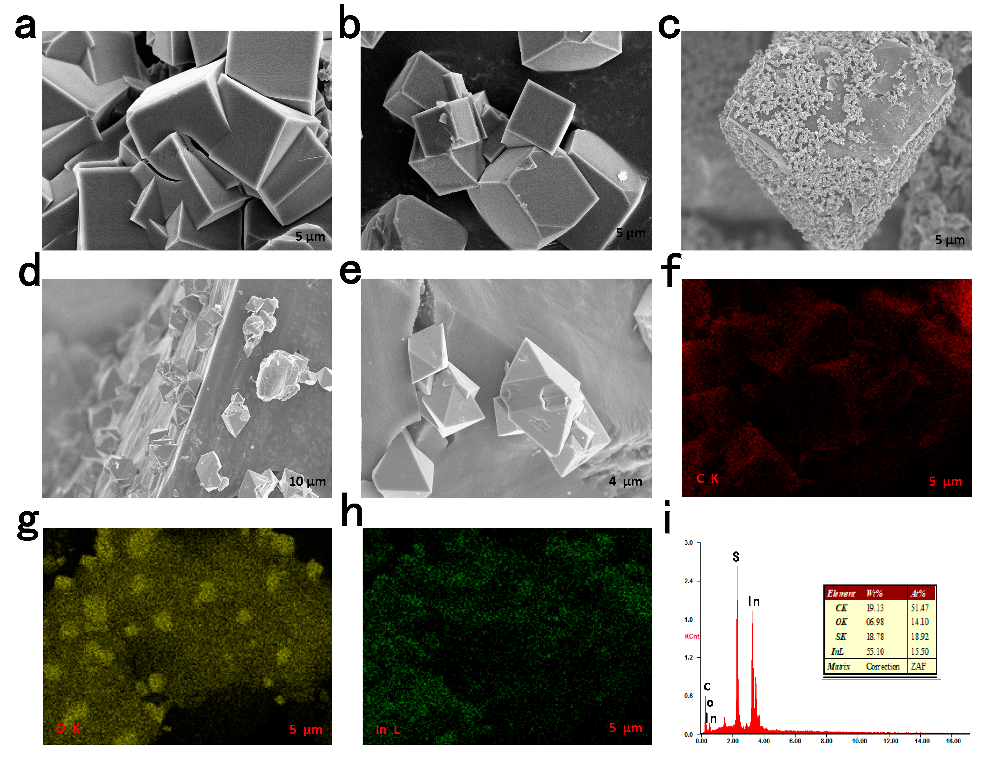
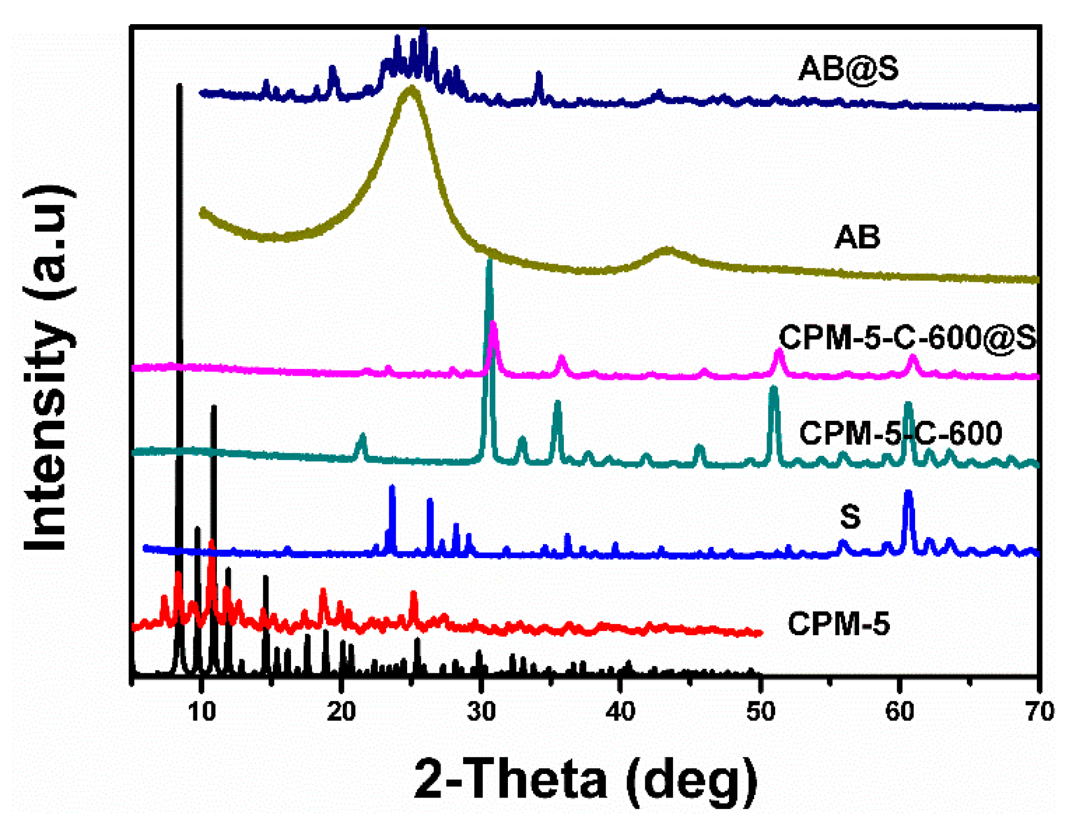
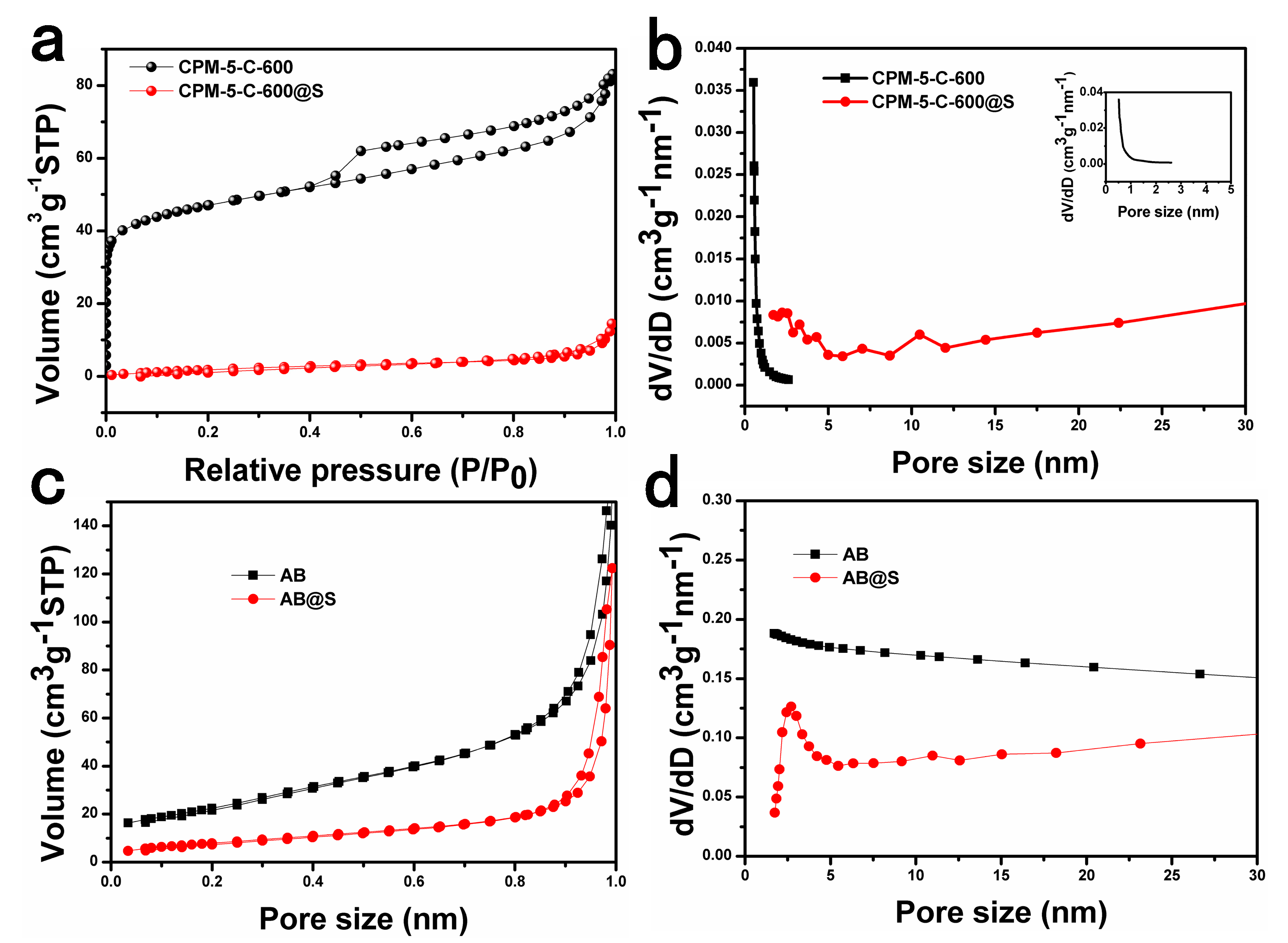
3.1. Characteristics

The CPM-5-C-600 was prepared through one-step carbonization of CPM-5, as illustrated in Figure 1. Firstly, CPM-5 crystal particles were synthesized by hydrothermal method at 120 °C in the reactor. The obtained crystal was not treated except for simple drying. Then, CPM-5-C-600 was achieved by high temperature carbonization at 600 °C. The SEM (Scanning electron microscopy) of CPM-5, CPM-5-C-600 and the elemental mapping of CPM-5-C-600@S are shown in Figure 2. Figure 2a,b is the morphology of CPM-5. It can be seen that CPM-5 has a regular cube structure, which is consistent with what had been reported previously. After high temperature carbonization at 600 °C, the morphology of CPM-5-C-600 is shown in Figure 2c–e. CPM-5-C-600 maintained the original cube shape, which also demonstrated the thermal stability of CPM-5 structure. However, there are some small rhombic crystals, which are attached to the surface of CPM-5-C-600. It is assumed that a part of Indium on the surface of CPM-5 structure is transformed into indium oxide at high temperature and deposited on the undamaged CPM-5. In addition to the presence of carbon, we found the indium and oxygen elements were distributed on the surface of CPM-5-C-600 uniformly after the EDS analysis and test. We didn’t choose to wash off the metal oxides on the surface with strong acid or alkali, because we supposed that the existence of metal oxides would form a specific core-shell structure with CPM-5-C-600 [24]. Therefore, the composite material will not only enhance the conductivity of the material and improve the rate performance of the battery, but also inhibit the intermediate product polysulfide, which will decrease the decay rate of polysulfide and promote the cycle stability of the battery [25]. To further characterize the sulfur distribution in the CPM-5-C-600@S, the EDX of CPM-5-C-600@S at the selected area is shown in Figure 2i, proving that the sulfur was homogenously absorbed within the CPM-5-C-600 host [26].
Powder X-ray diffraction patterns of the CPM-5, CPM-5-C-600, CPM-5-C-600@S, AB, and AB@S are shown in Figure 3. By comparing with the standard card, a large quantity of pure CPM-5 (gram-scale) can be readily prepared. The characteristic peak of CPM-5 can be seen between 5° and 10° obviously, which shows its good crystallinity. There is no impurity peak that indicates its good purity [21]. For AB, sharp diffraction peaks appearing near 26° and 44° are the characteristics of the carbon materials [26]. The peaks corresponding to the sulfur were observed from AB@S composite, indicating that the sulfur particles are distributed to the materials uniformly [27]. On the contrary, there were no obvious peaks appearing in the XRD profile of CPM-5-C-600, suggesting comparatively low graphite degree of the porous carbon derived from CPM-5 because of a low carbonization temperature [27,28]. Besides, the peaks at 31°, 36° and 52° have very strong diffraction intensity, which are the feature peaks of indium oxide [29]. This also verified our conjecture about indium oxide in SEM analysis. This indicates that central indium exists in MOF in the form of metal oxides after carbonization. The peaks of sulfur were not found in CPM-5-C@S, implying that the confining of sulfur within the CPM-5-C-600 pores is due to a relatively large pore volume and specific area.
The pore structure characteristics and pore size distribution of CPM-5-C-600, CPM-5-C-600@S, AB, and AB@S samples were listed in the figure through Brunauer-Emmett-Teller (BET) test. As shown in Figure 4a, the adsorption desorption curve of CPM-5-C-600 material shows obvious mesoporous and microporous composite structure. Through pore size analysis, we could see that there is a type of micropores (less than 1 nm) and a small amount of mesoporous (2.5 nm) on the basis of Density Functional Theory (DFT) method. Through the pore distribution structure of CPM-5-C-600, we speculate that when CPM-5-C-600@S was used as the cathode material of Li-S batteries, its microporous structure could limit the small polysulfide (S2–4) and prevent the transformation of small polysulfide into the large polysulfide (S6–8), which could improve the cycle stability of Li-S battery effectively [29]. In addition, the mesoporous structure can provide a path for the transportation of Li+, promote the diffusion rate of Li+, facilitate the infiltration of electrolyte, and elevate the conductivity and rate performance of the battery [30]. As the presence of indium oxide inhibited the adsorption of some pores on the gas, the nitrogen adsorption capacity of CPM-5-C-600 was only 80 cm3∙ g−1, which was lower than the previously reported MOF derived carbon and AB materials. And the adsorption capacity changed obviously when sulfur was poured into the material by melting diffusion. The decrease of adsorption indicates that sulfur has been successfully immersed into the pores of CPM-5-C-600, and the appearance of micro- and mesopores less than 5 nm indicates the impregnation of sulfur. The mesopores in the range of 6–20 nm could well adapt to the volume change of Li-S batteries during cycles.
The thermogravimetric test of CPM-5, CPM-5-C-600@S and AB@S materials were shown in the Figure 5 below. The curves of CPM-5 shows that the removal of solvent molecules occured in the temperature range of 40–230 °C and there was no further weight loss up to 300 °C. This exhibited that the CPM-5 structure had good thermal stability [21]. The carbonized CPM-5 tended to be stable above 350 °C, which also reflected its structural and thermal stability. It can be seen from the figure that the sulfur content of the two samples was 40% and 45% respectively. Both samples lost weight between 150 and 350 °C. However, by comparing the heat loss rate of two samples, we could find that the loss rate of sulfur in CPM-5-C-600@S sample was less than AB@S. This is because the bound function of CPM-5-C-600 sample to sulfur was stronger than that of AB sample, and the binding ability of sulfur to CPM-5-C-600 sample was better than that of AB sample [31]. It also provides the basis and guarantee for CPM-5-C-600 @S to be used as the cathode material of Li-S batteries, and was conducive to improve the cycle stability of the Li-S battery.

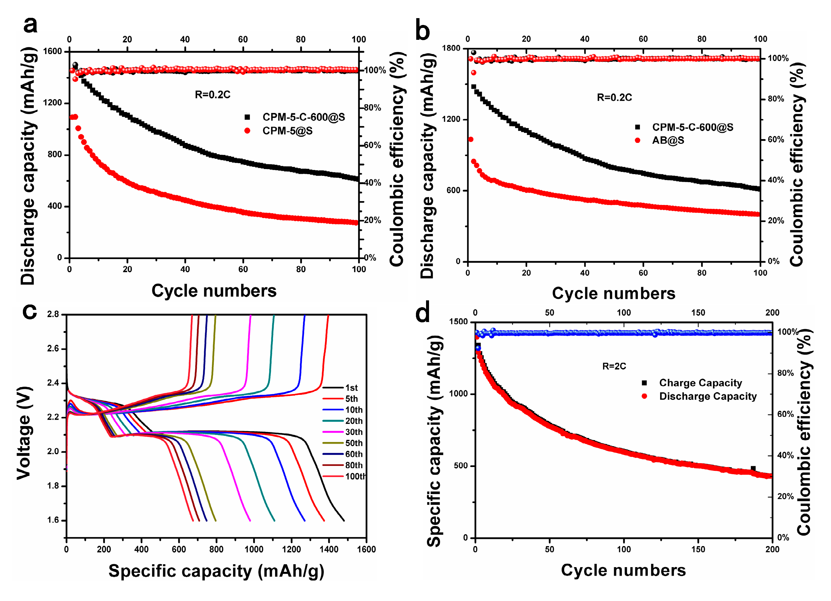
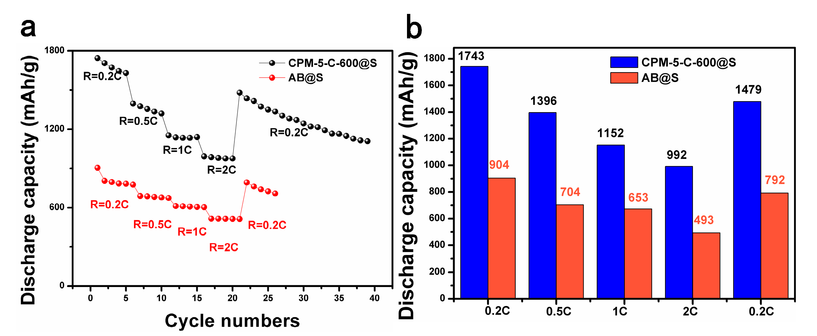
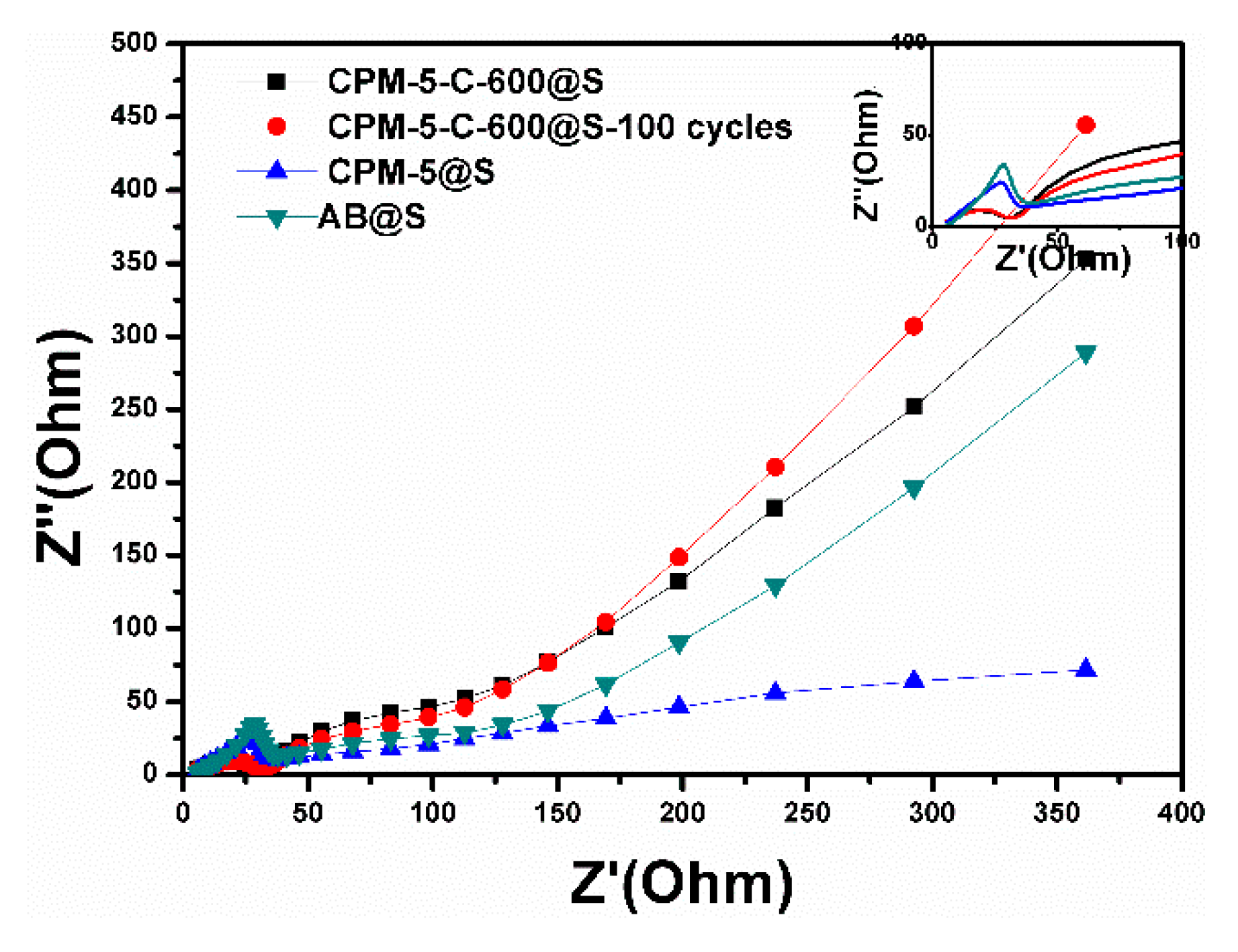
3.2. Electrochemical Performance

Within the potential range of 1.3 to 3.0 V and at a scanning rate of 0.1 mV∙s−1, initial three cycles CV behaviors of CPM-5-C@S electrode are shown in Figure 6a. During negative scanning, two reduction peaks centered at 1.9 and 2.25 V were observed, corresponding to the transformation of sulfur to soluble lithium polysulfides (Li2Sx, 4 ≤ x ≤ 8) and soluble polysulfide to the Li2S2/Li2S, respectively. By contrast, the oxidation peak at about 2.5 V exhibited the oxidation reaction of Li2S and Li2S2 to final oxidation products of S. With the cycle processing, the intensity of the reduction peak was decreasing gradually, but the degree was low which shows the battery had strong reversibility. The curve was smooth when the sweep speed was 0.1 mV∙s−1, which indicates that the lithiated of the battery was weak. As shown in Figure 6b, from the growth of redox current of AB@S to CPM-5-C-600@S electrode, because the structure of CPM-5 after 600 carbonization has more electrochemical active sites than AB [32].
In order to prove that indium oxide coated on CPM-5-C-600 contributes to inhibit the decay of polysulfide and improve the cycle stability of the battery, we used CPM-5@S and CPM-5-C-600@S as cathode of Li-S battery for 100 cycles at 0.2 C. When CPM-5@S was used as positive materials, the initial discharge specific capacity reached 1100 mAh∙g−1 and the capacity was maintained at 300 mAh∙g−1 after 100 cycles. Although the microporous of the CPM-5 could dominate the attenuation of polysulfide (S2–4), the capacity retention was too low due to the limitation of pore size. When CPM-5-C-600@S was used as cathode material, the first discharge specific capacity reached 1500 mAh∙g−1 and the ultimate capacity could be maintained at 650 mAh∙g−1, which shows that the presence of indium oxide did play an active role in arresting the “shuttle effect”. It slows down the dissolution by coating the spilled polysulfides, so as to increase the capacity retention rate and the cycle stability of the battery. To further evaluate the electrochemical performance of composite cathode, we compared the cycle performance of CPM-5-C-600@S and AB@S at a current density of 0.2 C as shown in Figure 7b. The high initial specific capacity of the CPM-5-C-600@S cathode assembled in the battery was much higher than the 1100 mAh·g−1 of the AB@S cathode. After 100 cycles, compared with 400 mAh∙g−1 of AB@S capacity, the high specific capacity of CPM-5-C-600@S is 650 mAh∙g−1, indicating good cycle stability. In addition, the constant current discharge-charge voltage profiles of the cells at 0.2 C are shown in Figure 7c. Two distinct discharge plateaus were observed for all discharge curves due to the conversion of element S8 to polysulfide and further reduction to Li2S/Li2S2 as discussed in CV measurements [33]. It can be seen from the figure that the capacity decayed quickly during the first cycle and the 50th cycle. The capacity of this part may be provided by the sulfur on the surface. In the later cycles, we could find that the capacity tended to be stable. This is the sulfur inside the channel that provides the capacity [34]. After 100 charge discharge cycles, the discharge specific capacity can still be maintained at 650 mAh∙g−1. The space between the curve is smaller and smaller with the cycle going on, which shows that the polarization phenomenon of the battery is weak, and the CPM-5-C-600@S has good cycling stability. The durability of the CPM-5-C-600@S electrode was further examined by charging and discharging at the current density of 2C for 200 cycles. As shown in Figure 7d, its initial discharge capacity was up to 1450 mAh∙g−1. After 200 cycles, it still maintained a high capacity of 500 mAh∙g−1, and the corresponding coulombic efficiency was about 100%. This also shows that the “Core-shell” composite formed by indium oxide and CPM-5-C-600@S buffer the volume expansion, which increases the structure stability of the positive material and elevates the constancy of the battery in the process of circulation under high current [35].
In order to prove that the conductivity of carbonized CPM-5 was significantly improved, we studied the rate performance of the battery. Figure 8a,b shows the rate performances of the CPM-5-C-600@S and AB@S cathodes. As the C-rate varied from 0.2 to 2 C, the discharge capacity of CPM-5-C-600@S and AB@S decreased gradually because of polarization. However, the CPM-5-C-600@S electrode was significantly higher than the AB@S electrode with the transformation of the rate. The CPM-5-C-600@S electrode could still maintain 1479 mAh·g−1 when the rate from 2 to 0.2 C, which was much higher than 792 mAh·g−1 of AB@S electrode. CPM-5-C-600@S electrode shows good conductivity and excellent cycle stability. We compared the electrochemical performance of the CPM-5-C-600@S cathode in this work with other related reported composite material derived from MOF. The results were summarized in Table 1.
The EIS curves of AB@S, CPM-5@S, CPM-5-C-600@S, and CPM-5-C-600@S-100 cycles cathodes are showed in Figure 9. The semicircle could reflect the resistance of the electrochemical reaction at the boundary of the electrode-electrolyte, which is called charge-transfer resistance [36]. We could see that the transfer resistance of CPM-5-C-600@S electrode material was less than that of AB@S and CPM-5@S electrode, which attributes to the special structure of CPM-5-C-600. On the other hand, the Li+ diffusion coefficient (slope of oblique line) of CPM-5-C@S electrode was larger than that of AB@S and CPM-5@S electrode, because the mesopores of CPM-5-C-600 structure increased the diffusion rate of Li+ and improves the conductivity of the battery [37,38]. After 100 charge discharge cycles at 0.2 C, the cell impedance remained stable with CPM-5-C-600@S cathode. During the discharge process, the solid sulfur was reduced to polysulfide and deposited on the carrier material. This will promote the transfer impedance between polysulfides and the carrier material, but the structure of carbonized CPM-5can effectively avoided this defect. The stability of the structure, micro- mesoporous combination and indium oxide particles made the composite material cathode reduce the deposition of lithium sulfide and the obstruction of Li+ diffusion process, so as to improve the conductivity of the battery [39,40].

4. Conclusions

In summary, CPM-5-C-600 was successfully obtained by hydrothermal and carbonization methods. Its unique micro-mesoporous composite structure and indium oxide solid particles obtained by carbonization were conducive to inhibiting the decay of polysulfide and improving the rate performance and cycle stability of the battery. When CPM-5-C-600@S was used as cathode a material of Li-S battery, the capacity was of 650 mAh·g−1 at 0.2 C of 100 cycles and 500 mAh·g−1 at 2 C of 200 cycles respectively. The coulombic efficiency was close to 100%.

Author Contributions

Conceptualization, G.H.; methodology, G.H. and X.W.; investigation, J.Y. and M.Z.; writing-original draft preparation, G.H. and J.Y.; writing-review and editing, G.H., and J.W.; project administration, J.W. All authors have read and agreed to the published version of the manuscript.

Funding

This work was partially supported by the National Natural Science Foundation of China (no. 51202179, 51702256), Shaanxi Province (no. 2013KJXX-57, 2018GY-166, 2019TD-019), Xi’an Key Laboratory of Clean Energy (no. 2019219914SYS014CG03), the Natural Science Foundation of Xi’an (201805033YD11CG17(7)) and the Science Foundation of Shaanxi Provincial Department of Education (no. 12JS060, 18JS058).

Acknowledgments

The authors deeply appreciate Lihong Chen from Analysis and Test center of School of Materials, Shaanxi University of Science and Technology, for providing help on SEM observation.

Conflicts of Interest

The authors declare no conflict of interest.

References

  1. Wang, C.; Kaneti, Y.; Bando, Y.; Lin, J.; Liu, C.; Li, J.; Yamauchi, Y. Metal-Organic Framework-Derived One-Dimensional Porous or Hollow Carbon-Based Nanofibers for Energy Storage and Conversion. Mater. Horiz. 2018, 5, 394–407. [Google Scholar] [CrossRef] [Green Version]
  2. Li, Y.; Xu, Y.; Yang, W.; Shen, W.; Xue, H.; Pang, H. MOF-Derived Metal Oxide Composites for Advanced Electrochemical Energy Storage. Small 2018, 14, 1704435. [Google Scholar] [CrossRef] [PubMed]
  3. Liu, W.; Chen, J.; Chen, Z.; Liu, K.; Zhou, G.; Sun, Y.; Song, M.-S.; Bao, Z.; Cui, Y. Stretchable Lithium-Ion Batteries Enabled by Device-Scaled Wavy Structure and Elastic-Sticky Separator. Adv. Energy Mater. 2017, 7, 1701076. [Google Scholar] [CrossRef]
  4. Zhang, H.; Zhang, L.; Chen, J.; Su, H.; Liu, F.; Yang, W. One-step synthesis of hierarchically porous carbons for high-performance electric double layer supercapacitors. J. Power Sources 2016, 315, 120–126. [Google Scholar] [CrossRef]
  5. Wan, J.; Xie, J.; Kong, X.; Liu, Z.; Liu, K.; Shi, F.; Pei, A.; Chen, H.; Chen, W.; Chen, J.; et al. Ultrathin, flexible, solid polymer composite electrolyte enabled with alighed nanoporous host for lithium batteries. Nat. Nanotechnol. 2019, 14, 705–711. [Google Scholar] [CrossRef]
  6. Bustamante, E.; Fernández, J.; Zamaro, J. Influence of the solvent in the synthesis of zeolitic imidazolate framework-8 (ZIF-8) nanocrystals at room temperature. J. Colloid Interface Sci. 2014, 424, 37–43. [Google Scholar] [CrossRef]
  7. Liu, K.; Kong, B.; Liu, W.; Sun, Y.; Song, M.-S.; Chen, J.; Liu, Y.; Lin, D.; Pei, A.; Cui, Y. Stretchable Lithium Metal Anode with Improved Mechanical and Electrochemical Cycling Stability. Joule 2018, 2, 1857–1865. [Google Scholar] [CrossRef] [Green Version]
  8. Su, H.; Huang, H.; Zhang, H.; Chu, X.; Zhang, B.; Gu, B.; Zheng, X.; Wu, S.; He, W.; Yan, C.; et al. In Situ Direct Method To Massively Prepare Hydrophilic Porous Carbide-Derived Carbons for High-Performance Supercapacitors. ACS Appl. Energy Mater. 2018, 1, 3544–3553. [Google Scholar] [CrossRef]
  9. Zhang, H.; Zhao, W.; Zou, M.; Wang, Y.; Chen, Y.; Xu, L.; Wu, H.; Cao, A. 3D, Mutually Embedded MOF@Carbon Nanotube Hybrid Networks for High-Performance Lithium-Sulfur Batteries. Adv. Energy Mater. 2018, 8, 1800013. [Google Scholar] [CrossRef]
  10. Ma, L.; Hendrickson, K.E.; Wei, S.; Archer, L.A. Nanomaterials: Science and applications in the lithium–sulfur battery. Nano Today 2015, 10, 315–338. [Google Scholar] [CrossRef] [Green Version]
  11. Pang, Q.; Liang, X.; Kwok, C.Y.; Nazar, L.F. Advances in lithium–sulfur batteries based on multifunctional cathodes and electrolytes. Nat. Energy 2016, 1, 16132. [Google Scholar] [CrossRef]
  12. Zhong, Y.; Xu, X.; Liu, Y.; Wang, W.; Shao, Z. Recent Progress in Metal–Organic Frameworks for Lithium–Sulfur Batteries. Polyhedron 2018, 155, 464–484. [Google Scholar] [CrossRef]
  13. Manthiram, A.; Fu, Y.; Chung, S.; Zu, C.; Su, Y. Rechargeable Lithium−Sulfur Batteries. Chem. Rev. 2014, 114, 11751–11787. [Google Scholar] [CrossRef] [PubMed]
  14. Shang, X.; Qin, T.; Guo, P.; Sun, K.; Su, H.; Tao, K.; He, D. A Novel Strategy for the Selection of Polysulfde Adsorbents toward High-Performance Lithium-Sulfur Batteries. Adv. Mater. 2019, 6, 1900393. [Google Scholar]
  15. Wu, Q.; Zhou, X.; Xu, J.; Cao, F.; Li, C. Carbon-based derivatives from metal-organic frameworks as cathode hosts for Li–S batteries. J. Energy Chem. 2019, 38, 94–113. [Google Scholar] [CrossRef] [Green Version]
  16. Yang, Y.; Wang, S.; Zhang, L.; Deng, Y.; Xu, H.; Qin, X.; Chen, G. CoS-interposed and Ketjen black-embedded carbon nanofiber framework as a separator modulation for high performance Li-S batteries. Chem. Eng. J. 2019, 269, 77–86. [Google Scholar] [CrossRef]
  17. Zhu, Q.; Zhao, Q.; An, Y.; Anasori, B.; Wang, H.; Xu, B. Ultra-microporous carbons encapsulate small sulfur molecules for high performance lithium-sulfur battery. Nano Energy 2017, 33, 402–409. [Google Scholar] [CrossRef]
  18. Song, J.; Gordin, M.L.; Xu, T.; Chen, S.; Yu, Z.; Sohn, H.; Lu, J.; Ren, Y.; Duan, Y.; Wang, D. Strong Lithium Polysulfide Chemisorption on Electroactive Sites of Nitrogen-Doped Carbon Composites For High-Performance Lithium-Sulfur Battery Cathodes. Angew. Chem. Int. Ed. 2015, 54, 4325–4329. [Google Scholar] [CrossRef]
  19. Xuan, W.; Zhu, C.; Liu, Y.; Cui, Y. Mesoporous metal–organic framework materials. Chem. Soc. Rev. 2012, 41, 1677–1695. [Google Scholar] [CrossRef]
  20. Wu, H.; Gong, Q.; Olson, D.; Li, J. Commensurate Adsorption of Hydrocarbons and Alcohols in Microporous Metal Organic Frameworks. Am. Chem. Soc. 2012, 112, 836–868. [Google Scholar] [CrossRef]
  21. Zheng, S.; Bu, J.; Li, Y.; Wu, T.; Zuo, F.; Feng, P.; Bu, X. Pore space partition and charge separation in cage-within-cage indium-organic frameworks with high CO2 uptake. J. Am. Chem. Soc. 2010, 132, 17062–17064. [Google Scholar] [CrossRef] [PubMed]
  22. Xi, K.; Cao, S.; Peng, X.; Ducati, C.; Kumar, R.V.; Cheetham, A.K. Carbon with hierarchical pores from carbonized metal–organic frameworks for lithium sulphur batteries. Chem. Commun. 2013, 49, 2192–2194. [Google Scholar] [CrossRef] [PubMed]
  23. Baumann, A.E.; Aversa, G.E.; Roy, A.; Falk, M.L.; Bedford, N.M.; Thoi, V.S. Promoting sulfur adsorption using surface Cu sites in metal-organic frameworks for lithium sulfur batteries. J. Mater. Chem. A 2018, 6, 4811–4821. [Google Scholar] [CrossRef]
  24. Shi, M.; Yan, Y.; Wei, Y.; Zou, Y.; Deng, Q.; Wang, J.; Yang, R.; Xu, Y.; Han, T. Fabrication of ultrafine Gd2O3 nanoparticles/carbon aerogel composite as immobilization host for cathode for lithium-sulfur batteries. Int. J. Energy Res. 2019, 43, 7614–7626. [Google Scholar]
  25. Jiang, H.; Liu, X.; Wu, Y.; Shu, Y.; Deng, H. Metal-organic frameworks for high charge-discharge rates in lithium-sulfur batteries. Angew. Chem. Int. Ed. 2018, 57, 3916–3921. [Google Scholar] [CrossRef]
  26. Yu, F.; Zhou, H.; Shen, Q. Modification of cobalt-containing MOF-derived mesoporous carbon as an effective sulfur-loading host for rechargeable lithium-sulfur batteries. J. Alloys Compd. 2019, 772, 843–851. [Google Scholar] [CrossRef]
  27. Yang, X.; Yan, N.; Zhou, W.; Zhang, H.; Li, X.; Zhang, H. Sulfur embedded in one-dimension French fries-like hierarchical porous carbon derived from metal organic framework for high performance lithium-sulfur batteries. J. Mater. Chem. A 2015, 3, 15314–15323. [Google Scholar] [CrossRef]
  28. Hu, M.; Reboul, J.; Furukawa, S.; Torad, N.L.; Ji, Q.; Srinivasu, P.; Ariga, K.; Kitagawa, S.; Yamauchi, Y. Direct carbonization of al-based porous coordination polymer for synthesis of nanoporous carbon. J. Am. Chem. Soc. 2010, 134, 2864–2867. [Google Scholar] [CrossRef]
  29. Wang, J.; Zhai, Q.; Li, S.; Jiang, Y.; Hu, M. Mesoporous In2O3 materials prepared by solid-state thermolysis of indium-organic frameworks and their high HCHO-sensing performance. Inorg. Chem. Commun. 2016, 63, 48–52. [Google Scholar] [CrossRef]
  30. Xu, G.; Ding, B.; Shen, L.; Nie, P.; Han, J.; Zhang, X. Sulfur embedded in metal organic framework-derived hierarchically porous carbon nanoplates for high performance lithium–sulfur battery. J. Mater. Chem. A 2013, 1, 4490–4496. [Google Scholar] [CrossRef]
  31. Fan, L.; Wu, H.; Wu, X.; Wang, M.; Cheng, J.; Zhang, N.; Feng, Y.; Sun, K. Fe-MOF derived jujube pit like Fe3O4/C composite as sulfur host for lithium-sulfur battery. Electrochim. Acta 2019, 295, 444–451. [Google Scholar] [CrossRef]
  32. Chen, X.; Peng, L.; Yuan, L.; Zeng, R.; Xiang, J.; Chen, W.; Yuan, K.; Chen, J.; Huang, Y.; Xie, J. Facile synthesis of Li2S@C composites as cathode for Li–S batteries. J. Energy Chem. 2019, 37, 111–116. [Google Scholar] [CrossRef] [Green Version]
  33. Geng, P.; Cao, S.; Guo, X.; Ding, J.; Zhang, S.; Zheng, M.; Pang, H. Polypyrrole indexing hollow metal-organic framework composites for lithium-sulfur batteries. J. Mater. Chem. A 2019, 7, 19465–19470. [Google Scholar] [CrossRef]
  34. Wu, H.; Wei, S.; Zhang, L.; Xu, R.; Hng, H.; Lou, X. Embedding Sulfur in MOF-Derived Microporous Carbon Polyhedrons for Lithium–Sulfur Batteries. Chem. A Eur. J. 2013, 19, 10804–10808. [Google Scholar] [CrossRef] [PubMed]
  35. Zhang, H.; Zhao, W.; Wu, Y.; Wang, Y.; Zou, M.; Cao, A. Dense monolithic MOF and carbon nanotube hybrid with enhanced volumetric and areal capacities for lithium-sulfur battery. J. Mater. Chem. A 2019, 7, 9195–9201. [Google Scholar] [CrossRef]
  36. Su, Y.; Manthiram, A. Lithium-sulphur batteries with a microporous carbon paper as a bifunctional interlayer. Nat. Commun. 2012, 3, 1166. [Google Scholar] [CrossRef] [Green Version]
  37. Bao, W.; Su, D.; Zhang, W.; Guo, X.; Wang, G. 3D Metal Carbide@Mesoporous Carbon Hybrid Architecture as a New Polysulfide Reservoir for Lithium-Sulfur Batteries. Adv. Funct. Mater. 2016, 26, 8746–8756. [Google Scholar] [CrossRef]
  38. Xu, G.; Zou, Y.; Huang, B. Metal-organic framework-74-Ni/carbon nanotube composite as sulfur host for high performance lithium-sulfur batteries. J. Electroanal. Chem. 2018, 830, 43–49. [Google Scholar] [CrossRef]
  39. Bao, W.; Zhang, Z.; Qu, Y.; Zhou, C.; Wang, X.; Li, J. Confine sulfur in mesoporous metal–organic framework @ reduced graphene oxide for lithium sulfur battery. J. Alloys Compd. 2014, 582, 334–340. [Google Scholar] [CrossRef]
  40. Xu, S.; Liang, X.; Wu, X.; Zhao, S.; Chen, J.; Wang, K.; Chen, J. Multistage discharge constructing hererostructure with enhanced solid-solution behavior for long-life lithium-oxygen batteries. Nat. Commun. 2019, 10, 5810. [Google Scholar] [CrossRef] [Green Version]
Figure 1. The Schematic illustration of the CPM-5-C-600@S composite preparation.
Nanomaterials 10 00177 g001
Figure 2. SEM images of: (a,b) CPM-5 and (ce) CPM-5-C-600. (fh) The elemental mapping of Indium oxide particles of CPM-5-C-600. (i) The corresponding EDX of CPM-5-C-600@S.
Nanomaterials 10 00177 g002
Figure 3. The XRD patterns ofCPM-5, S, AB, AB@S, CPM-5-C-600 and CPM-5-C-600@S composites.
Nanomaterials 10 00177 g003
Figure 4. (a) Nitrogen adsorption-desorption isotherms and (b) pore size distribution curves of CPM-5-C-600 and CPM-5-C-600@S composites. (c) Nitrogen adsorption-desorption isotherms, and (d) pore size distribution curves of AB and AB@S composites.
Nanomaterials 10 00177 g004
Figure 5. TGA curves of the CPM-5, CPM-5-C-600@S and AB@S composites.
Nanomaterials 10 00177 g005
Figure 6. Cyclic voltammetry (CV) curves of (a) CPM-5-C@S electrodes at a scanning rate of 0.1 mV s−1 range from 1.3 to 3.0 V with 5 cycles; (b) CV curves of CPM-5-C@S and AB@S electrodes at the second cycle.
Nanomaterials 10 00177 g006
Figure 7. (a) Cycling performance of CPM-5-C-600@S and CPM-5@S electrodes at 0.2 C. (b) Cycling performance of CPM-5-C-600@S and AB@S electrodes at 0.2 C; (c) Discharge/charge curves of CPM-5-C-600@S electrodes at 0.2 C; (d) Cycling performance of CPM-5-C-600@S electrodes at 2 C.
Nanomaterials 10 00177 g007
Figure 8. (a,b) C-rate performance for CPM-5-600@S and AB@S cathodes at various C-rate from 0.1 C to 2 C.
Nanomaterials 10 00177 g008
Figure 9. The EIS of AB@S, CPM-5@S, CPM-5-C600@S electrodes in Li-S batteries before cycles and the CPM-5-C-600@S-100 cycles electrodes.
Nanomaterials 10 00177 g009
Table 1. Electrochemical performances of CPM-5-C-600@S electrode in this work and other similar composition reported in other references as cathode in Li-S battery.
SamplesInitial CapacityCycling StabilityRate CapacityReference
CPM-5-600-C@S1500 mAh g−1794 mAh g−1 at 0.2 C after 50 cycles
650 mAh g−1 after 100 cycles
992 mAh g−1 at 2 Cthis work
CoS/KB1500 mAh g−1600 mAh g−1 at 0.5 C after 200 cycles700 mAh g-1 at 2 C[16]
MOF-74/CNT1065 mAh g−1610 mAh g−1 at 0.5 C after 100 cycles667 mAh g−1 at 2 C[38]
Fe3O4/C/S1050 mAh g−1750 mAh g−1 at 0.2 C after 50 cycles640 mAh g−1 at 1 C[31]
HPCN-S(MOF-5)1177 mAh g−1730 mAh g −1 at 0.5 C after 50 cycles/[30]
C from ZnFumarate1500 mAh g−1650 mAh g−1 at 400 mA g−1 after 40 cycles/[22]
MIL-101@rGO/S980 mAh g−1650 mAh g−1 at 335 mA g−1 after 50 cycles980 mAh g−1 at 0.2 C[39]
S/Gd2(Gd2O3)-CA1210 mAh g−1555 mAh g−1 at 0.1 C after 50 cycles420 mAh g−1 at 1 C[24]
S/FLHPC1206 mAh g−1856 mAh g−1 at 0.2 C after 100 cycles763 mAh g−1 at 2 C[27]

