Abstract
We report a non-hydrolytic sol-gel (NHSG) route to engineer original mesoporous TinO2n−1@TiO2/C nanocomposites. The synthetic approach is straightforward, solvent-free, additive-free, and meets the challenge of atom economy, as it merely involves TiCl4 and THF in stoichiometric amounts. We found that these nanocomposites present enhanced electrocatalytic properties towards the oxygen reduction reaction (ORR) in 0.1 M KOH. We believe that these preliminary results will open a window of opportunity for the design of metal suboxides/carbon nanocomposites through NHSG routes.
1. Introduction
Titanium suboxides have received considerable attention in the last decades due to their remarkable electronic and optical properties [1,2,3]. Titanium suboxides can be classified in two main families [4,5]: (i) oxygen-deficient titanium oxides, namely, TiO2−x (where 0.001 > x > 0) or black TiO2 [6], which present point defects such as oxygen vacancies and titanium interstitials [7]; (ii) Magnéli phases, namely, TiO2−x (where 0.25 > x > 0.001), for which the off-stoichiometry is accommodated by extended defects and changes in the crystal structure. Magnéli phases, also noted as TinO2n−1 (where n varies from 4 to 37) and first described in the 1950s by Magnéli et al. [8,9], present crystallographic shear (CS) planes, and can be seen as ordered combinations of rutile TiO2 and corundum Ti2O3 structures [3,4]. Note that, in contrast to Magnéli phases, Ti3O5 structures [10] (TinO2n−1, where n = 3) have no CS planes. However, as they satisfy the TinO2n−1 formula, Ti3O5 polymorphs have often been considered as the first members of the Magnéli phases’ family. Titanium suboxides depict remarkable properties [3,11,12], amongst which are electrochemical stability, high electronic conductivity (c.a. 10.4 S cm−1 for Ti4O7 at room temperature [13]), high electron mobility (>0.5 cm2 V−1 s−1 for Ti4O7 at room temperature [1]), and low band-gap as compared with stoichiometric TiO2 (about 0.5 eV smaller than that of TiO2 anatase [14]). Thus, titanium suboxides have been widely investigated in electrocatalysis [15,16,17,18,19], photocatalysis [20,21,22,23] and energy storage devices [24,25].
Several synthesis routes have been reported in the literature for the preparation of titanium suboxides, either defective or Magnéli phases. Most of them start from stoichiometric TiO2 and involve oxygen scavengers such as zirconium foil [19,26] and/or reducing agents such as carbon (through carbothermal reduction) [27,28,29], CaH2 at low temperature (350–450 °C) [30,31], or hydrogen gas at temperatures typically higher than 950 °C [24]. Amongst them, the carbothermal reduction approach is particularly interesting. It generally implies external carbon sources, usually from organic additives, combined to the oxide by sol-gel process and yielding, after carbothermal reduction, TinO2n−1/C composites in simple, one-pot, bottom-up approaches [28]. The sol-gel process has been largely used for the preparation of advanced metal-oxide materials, such as TiO2. This process presents numerous advantages, including versatility and scalability, and can be conducted under mild condition (T ≤ 100 °C, 1 atm). Regarding titanium suboxides, a few studies have been reported on sol-gel/carbothermal reduction routes starting from commercial titanium alkoxides and organic additives, such as poly(ethyleneimine), polyethyleneglycol [28], poly(styrene-b-2-vinylpyridine) [32], resol [25], or glucose [29]. Following such a procedure, Portehault et al. [28] obtained single-phase Magnéli/carbon nanocomposites with both structural (TinO2n−1 with n = 8, 6, 5, 4, or 3) and textural control by tuning the Ti:C ratio, the nature of the carbon source and the calcination atmosphere (argon versus nitrogen). More recently, Huang et al. [29] prepared various TinO2n−1/C nanocomposites employing glucose as the carbon source and a carbothermal reduction process under vacuum. The authors demonstrated the importance of the cooling conditions which govern the predominant titanium suboxide phase obtained in fine (n = 4, 3, 2, or 1). Those are two good examples that demonstrate the versatility of the sol-gel process combined to carbothermal reduction to design TinO2n−1/C nanocomposites. Although innovative and efficient, most of these approaches rely on relatively expensive precursors (e.g., synthetic polymers) and/or require organic additives in a large excess, making the all procedure wasteful of resources. With this aim, we propose hereafter to investigate an original one-pot, atom-economic synthesis route to prepare TinO2n−1/C nanocomposites using the non-hydrolytic sol-gel process (NHSG).
Unlike conventional aqueous sol-gel processes, NHSG is performed in organic medium and involves organic oxygen donors such as ethers or alcohols instead of water [33,34]. NHSG offers simple, one-step routes to produce oxide-based materials with well controlled compositions and textures, avoiding the use of expensive precursors or reactivity modifiers [33]. The main drawback of NHSG lies in the necessity to work under anhydrous conditions and at higher temperature (up to 200 °C) and pressure (up to c.a. 30 bars) than conventional aqueous sol-gel methods, which may hamper industrial applications. Nevertheless, NHSG has been established as a versatile methodology for the synthesis of mesoporous metal-oxides and mixed oxides in the absence of templating agents or costly drying procedures [35], metal oxide nanocrystals [36,37,38,39] as well as organic-inorganic hybrids [40,41] and metal-oxide/carbon nanocomposites [42,43]. Recently, we reported a solvent-free NHSG route to synthesize TiO2/C nanocomposites based on the reaction of simple ethers (diisopropyl ether or tetrahydrofuran, THF) in a stoichiometric amount with titanium tetrachloride [42]. In this atom-economic process, the ether acted not only as an oxygen donor, but also as the sole carbon source, yielding anatase TiO2 nanocrystals coated by an amorphous carbon film [42]. Herein, we further extend this original approach to the preparation of titanium suboxides, by demonstrating that TinO2n−1 phases can be easily generated by partial carbothermal reduction of the TiO2/C nanocomposites at relatively low temperature, i.e., 950 °C, under argon flow. This solvent-free, additive-free approach is straightforward, and the partial reduction of TiO2 into TinO2n−1 phases (with 2 ≤ n ≤ 6) allows engineering original mesoporous TinO2n−1@TiO2/C nanocomposites. The latter are rarely targeted as such, researchers generally focussing on pure phases, but we found that this nano-assembly presents enhanced electrocatalytic properties towards the oxygen reduction reaction (ORR) in 0.1 M KOH. We believe that these preliminary results open new opportunities for the atom-economic design of metal suboxides/carbon nanocomposites through NHSG routes.
2. Materials and Methods
2.1. Materials Synthesis
To avoid water, all manipulations were carried out in a glovebox under argon atmosphere (<10 ppm of water and O2). Titanium(IV) chloride 99%, (Sigma-Aldrich Chemie, Saint-Quentin Fallavier, France) was used as received. Tetrahydrofuran (THF) 99.8%, (Fisher Scientific, Hampton, NH, USA) was dried over a PureSolve MD5 solvent purification system (Innovative Technology Inc., Amesbury, MA, USA). The amount of water in THF was controlled with a Karl Fischer coulometer (SI Analytics, Mainz, Germany) before reaction (H2O < 5 ppm).
The synthesis route is well-established and was already reported in our previous work [42]. Typically, TiCl4 (12.52 mmol, 1.37 mL) and THF (25.04 mmol, 2.03 mL) were added into a 23 mL stainless steel digestion vessel with a polytetrafluoroethylene (PTFE) lining from Parr Instrument Company (Moline, IL, USA). The sealed digestion vessel was heated in an oven at 180 °C for 4 days under autogenous pressure. The gel was dried under vacuum at 120 °C for 5 h, yielding a xerogel labeled xer-TiO2. The resulting xerogel was pyrolyzed under argon atmosphere (50 mL min−1) at 850 or 950 °C for 1 to 8 h (heating rate 10 °C min−1) to obtain TinO2n−1@TiO2/C nanocomposites. These nanocomposites are labeled TiO2/C-x-y, with x the first digit of the plateau temperature in degrees Celsius; and y the duration at the plateau in hours. For example, TiO2/C-9-8 stands for the sample pyrolyzed at 950 °C for 8 h. For comparison, a TiO2 sample was obtained by calcination in air (50 mL min−1) of the xerogels at 500 °C for 5 h (heating rate 10 °C min−1). This sample is labeled TiO2-5-5.
2.2. Characterization
Thermogravimetric analyses (TGA) were carried out using a Netzsch Simultaneous Thermal Analyzer STA 409 PC Luxx (Netzsch, Selb, Germany), with a heating rate of 10 °C min−1 in the 20–1000 °C range, under a dry air atmosphere or under argon (50 mL min−1). X-Ray diffraction (XRD) patterns were obtained using a PANalytical X’Pert Pro MPD diffractometer (Malvern PANalytical Ltd, Malvern, UK), with the Kα radiation of Cu (λ = 1.5418 Å) and a step size of 0.033° (2θ scale) into the 10–70° interval. N2-physisorption experiments were carried out at −196 °C on a Micromeritics TriStar 3000 (Micromeritics France, Merignac, France). Samples were out-gassed under vacuum at 110 °C overnight. Equivalent BET specific surface areas (SSABET) were determined in the relative pressure range P/P0 from 0.08 to 0.25. The total pore volume (V0.99) was measured at P/P0 = 0.99. Transmission electron microscopy (TEM) images were acquired with a JEOL 1200 microscope (JEOL Europe, Croissy sur Seine, France). High resolution TEM analysis was performed on a JEOL 2200FS microscope (JEOL Europe, Croissy sur Seine, France) operated at 200 kV from the MEA platform (Université de Montpellier, Montpellier, France). This microscope is equipped with a field emission gun (FEG) and an in-column Omega-type energy filter. STEM-EDX (Scanning Transmission Electron Microscopy) mapping were performed using a probe size of 1.5 nm and X-rays measured with a silicon drift detector (30 mm2, JEOL) with a collection solid angle of 0.13 sr.
2.3. Electrochemical Properties
A standard ink was prepared by mixing 10 mg of material with 300 µL of a Nafion® binder solution and 700 µL of absolute ethanol. The ink was ultrasonicated for at least 30 min for homogenization. A 5 µL aliquot was dropped onto a freshly polished glassy carbon rotating disk electrode (diameter 3 mm, electrode area 0.071 cm2) to prepare a catalyst thin film. The electrode was warmed to 40 °C in an oven prior to ink application in order to achieve better electrode coverage of the catalyst film. Electrochemical tests were performed in 0.1 M KOH (70 mL) in a standard three-electrode setup with an Ag/AgCl reference electrode and a Pt wire counter electrode. We used a RRDE-3A device (ALS Co. Ltd, Tokyo, Japan) to perform the rotating disk electrode (RDE) hydrodynamic measurements, a BioLogic VSP-300 potentiostat (BioLogic, Seyssinet-Pariset, France) and the EC-Lab® Software (BioLogic, Seyssinet-Pariset, France). Koutecky–Levich analyses were performed as described in literature [44] (for more details, see Appendix A).
3. Results
3.1. Synthesis and Characterization
3.1.1. NHSG Ether Route and Carbothermal Reduction: Mechanistic Insights
The NHSG ether route has been extensively used to prepare metal oxides, especially for the synthesis of titanium oxides [33,35,45]. In our previous works, we reported on the synthesis of TiO2 nanocrystals and TiO2/C nanocomposites from TiCl4 and THF [42]. This approach is based on the intermediate formation of alkoxide groups, which then condense with Ti-Cl to form oxo bridges (step (1) in Figure 1). In the case of THF and at moderate temperature (below 110 °C), the major organic by-product is 1,4-dichlorobutane. At higher reaction temperature, typically at 180 °C as used herein, secondary reactions are favoured, especially the formation and polymerization of alkenes resulting from the elimination of HCl (step (2) and (3) in Figure 1). These reactions, most probably catalyzed by the freshly produced TiO2 particles and HCl, can form highly cross-linked polymers, as shown in Figure 1. In a previous article [42], we showed that after pyrolysis at 750 °C under argon, we could take advantage of these highly cross-linked polymers to prepare TiO2/C nanocomposites (step (4) in Figure 1). Herein, we propose to investigate thermal post-treatments at higher temperatures, i.e., 850 and 950 °C, and to explore the opportunity to design TinO2n−1@TiO2/C nanocomposites through carbothermal reduction (step (5) in Figure 1).
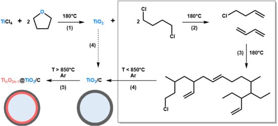
Figure 1.
Schematic representation of the non-hydrolytic sol-gel (NHSG) route developed herein to prepare TiO2, TiO2/C and TinO2n−1@TiO2/C nanocomposites. (1) Alkoxylation/Condensation; (2) Dehydrochlorination; (3) Polymerization; (4) Carbonization; and (5) Partial carbothermal reduction. In this representation, xer-TiO2 corresponds to TiO2 together with organic by-products (box on the right side) before step (4).
The presence of a large amount of organic cross-linked polymers in the xerogel obtained right after NHSG and subsequent drying, labeled xer-TiO2, was confirmed by thermogravimetric analysis (TGA) under synthetic dry air flow, as shown by the weight loss of about 31 wt.% from 240 °C to 550 °C (Figure 2a). To assess the carbothermal reduction process, TGA was also performed under argon flow on xer-TiO2 (Figure 2b). As mentioned above, this xerogel contains TiO2, oxygen-poor cross-linked polymers, and some residual chlorine atoms bonded to carbon [42]. On the TGA curve, three main weight loss regions can be seen: (i) in the temperature range 40–200 °C, with a weight loss of about 2 wt.%; (ii) in the temperature range 280–500 °C, with a weight loss of about 14 wt.%; and (iii) in the temperature range 850–1000 °C, with a weight loss of about 2 wt.% (Figure 2b). While the first region is most probably related to the elimination of residual volatile compounds, the second region can be attributed to the carbonization of the cross-linked polymers through inter- and intramolecular reactions such as dehydrochlorination. The third region might be attributed to the partial carbothermal reduction of TiO2 to TinO2n−1.
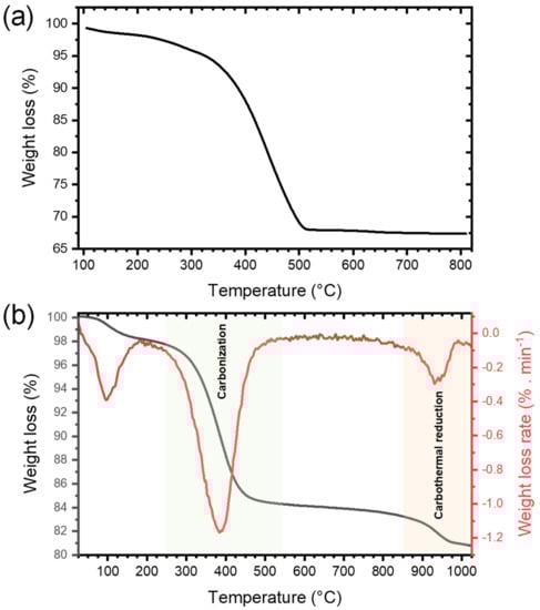
Figure 2.
Thermogravimetric analyses performed (a) under synthetic dry air flow (50 mL min−1) and (b) under argon flow (50 mL min−1) at 10°C min−1 of xer-TiO2.
3.1.2. TiO2 and TiO2/C Nanocomposites: Characterization
TiO2/C nanocomposites were prepared by pyrolysis of xer-TiO2 at 950 °C for 1, 2 and 8 h. For comparison, xer-TiO2 was also pyrolyzed at 850 °C for 4 h, or calcined in air at 500 °C for 5 h. These materials were thoroughly characterized by TGA, elemental analysis, X-ray diffraction (XRD), nitrogen sorption at 77 K, and transmission electron microscopy (TEM).
The TGA curves of the samples pyrolyzed at 950 °C (TiO2/C-9-y samples) were nearly identical, whatever the duration of the pyrolytic treatment. The total weight loss is much lower than the one of xer-TiO2 (c.a. 6–7 wt.%, Table 1) and starts at higher temperature, above 450 °C. Interestingly, a significant weight gain was observed in the temperature range 300–500 °C for the TiO2/C-9-y samples (Figure 3). This feature can be ascribed to the re-oxidation of titanium suboxides and has already been reported for TinO2n−1/C nanocomposites in the same temperature range [29].

Table 1.
Chemical composition, textural and structural properties of xer-TiO2, TiO2-5-5 and the different TiO2/C-x-y samples.
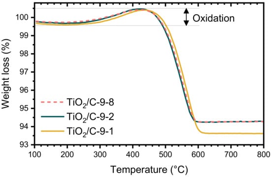
Figure 3.
Thermogravimetric analyses (TGA) performed under synthetic dry air flow (50 mL min−1) at 10 °C min−1 of TiO2/C-9-y samples.
The formation of titanium suboxide in the TiO2/C-x-y samples was confirmed by XRD (Figure 4, Table 1). While anatase (A) was the major phase present in all the samples, several peaks attributed to Ti3O5 (monoclinic) and Ti6O11 were observed for the TiO2/C-9-y samples, showing that carbothermal reduction of TiO2 occurred at 950 °C. Conversely, in the case of the sample pyrolyzed at 850 °C, TiO2/C-8-4, a significant amount of rutile (R) was detected, as reported in our previous work [42], but no suboxide phase was identified, indicating that carbothermal reduction did not take place at this temperature. The presence of a substantial amount of anatase (A) after pyrolysis at 850 °C and 950 °C is remarkable, since the anatase to rutile crystal transition usually occurs below 700 °C [46]. As reported in literature [47], the presence of carbon layers onto coated titanium dioxyde particles can suppress the anatase to rutile phase transformation by preventing sintering and crystal growth. In our previous works [42,48], the same feature was observed for TiO2/C nanocomposites prepared by a similar NHSG procedure and pyrolyzed under argon atmosphere at 750 and 900 °C. Our results suggested that the carbon content, which was related to the thickness of the carbon layer onto TiO2 nanoparticles, strongly affects the anatase to rutile crystal transition [48]. No significant difference was observed between the patterns of the three samples of the TiO2/C-9-y series, confirming that the duration of the pyrolytic treatment did not influence the carbothermal reduction process. Note that the sole difference, observed in the 32–33° (2θ) region (Figure 4), suggests that a longer pyrolytic treatment at 950 °C might favor Ti6O11 over Ti3O5. Even though elemental analysis and TGA indicated that about 6 wt.% C remained in the TiO2/C-9-y samples, the presence of anatase indicates that the carbothermal reduction at 950 °C was incomplete, whereas in recent studies reported in the literature, either single-phase Magnéli [28,32] or predominant suboxide phases with a small amount of rutile and anatase [29] were obtained by carbothermal reduction below 1000 °C. Particularly, Huang et al. [29] obtained various titanium suboxides from Ti4O7 to TiO with a C:Ti molar ratio in the xerogel between 1.1 and 6.5. In our case, we employed a C:Ti molar ratio of 1.9 (i.e., 20 wt.% of carbon in xer-TiO2, Table 1), which should theoretically be sufficient to fully reduce TiO2. While the C:Ti molar ratio did not seem critical herein, several factors may explain the incomplete reduction of TiO2. This will be discussed later.
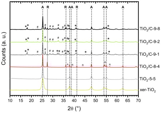
Figure 4.
X-ray diffraction (XRD) patterns of xer-TiO2, TiO2-5-5, and the TiO2/C-x-y series. A: Anatase; R: Rutile; : Ti3O5 (monoclinic); #: Ti6O11.
Besides structural properties, textural and morphological properties were investigated. The nitrogen sorption isotherms of xer-TiO2, TiO2-5-5, and the TiO2/C-x-y series are shown in Figure 5. The associated textural data are compiled in Table 1. All the samples are mesoporous, which is in good agreement with our previous works on TiO2-based materials obtained by NHSG ether routes [42]. According to the IUPAC classification [49], the isotherms are of type IV, corresponding to mesoporous solids with interparticle porosity. The TiO2/C-x-y samples, especially the ones treated at 950 °C, depict significantly higher specific surface areas and pore volumes than xer-TiO2 and TiO2-5-5. This feature suggests that the carbonaceous phase is highly porous, most probably due to the thermal degradation of the organic cross-linked polymer phase during pyrolysis.
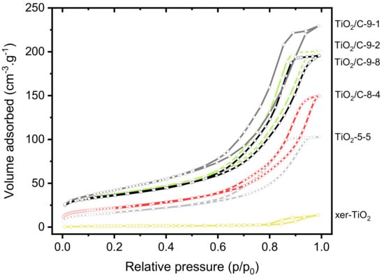
Figure 5.
Nitrogen sorption isotherms at 77 K of xer-TiO2, TiO2-5-5 and the different TiO2/C-x-y samples prepared herein.
The presence of a porous carbon phase was confirmed by TEM (Figure 6). While xer-TiO2 is composed of large agglomerates of TiO2 anatase nanocrystals with a diameter inferior to 20 nm (Figure 6a), TiO2/C-9-1 is composed of larger nanoparticles of ca. 50 nm embedded in a mesoporous carbon matrix (Figure 6b,c). These mesopores have a diameter of ca. 10 nm, in the range of the native TiO2 anatase nanocrystals. One may assume that these mesopores were generated during the thermal post-treatment, due to the migration/growth of TiO2 nanocrystals through the carbon matrix and the consumption of carbon atoms during the carbothermal reduction process. STEM-EDX mapping on TiO2/C-9-1 confirmed that TiO2 and/or TinO2n−1@TiO2 nanocrystals are surrounded by a carbon film.
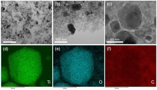
Figure 6.
Transmission electron microscopy (TEM) images of (a) xer-TiO2 and (b) TiO2/C-9-1. (c) High resolution TEM image and (d–f) STEM-EDX mapping of TiO2/C-9-1. The corresponding element (Ti, O or C) is noted in the bottom left corner of each image.
3.2. Electrochemical Properties Towards the Oxygen Reduction Reaction (ORR)
To demonstrate the superior properties of the TinO2n−1@TiO2/C nanocomposites prepared herein, we proposed to assess their electrocatalytic activity towards the oxygen reduction reaction (ORR). The ORR is one of the most studied reactions in the field of electrochemistry, especially when dealing with energy storage and conversion devices [50,51]. In particular, ORR in aqueous alkaline media [52] has been widely studied and is of great interest for applications in metal-air batteries [53] and alkaline anion-exchange membrane fuel cells [54]. In aqueous alkaline media, ORR can proceed either by a direct four-electron pathway to directly reduce O2 into hydroxide ions (Equation (1)), or by a two-electron pathway with formation of peroxide ions as intermediate species (Equation (2)), followed by a two-electron reduction to hydroxide ions (Equation (3)) or disproportionation (Equation (4)).
Cyclic voltammetry (CV) measurements were carried out in O2-saturated 0.1 M KOH solution. The CV curves obtained for TiO2/C-9-1 present a well-defined cathodic peak centered between −0.3 and −0.4 V vs. Ag/AgCl (Figure 7a), demonstrating the electrocatalytic activity of this material towards the ORR. In order to thoroughly compare the electrochemical properties of each material, linear sweep voltammetry (LSV) was performed and polarization curves were recorded from 0.2 to −1.0 V vs. Ag/AgCl, at a rotation rate of 1600 rpm (Figure 7b). The presence of an intermediary current plateau (between −0.4 and −0.6 V for TiO2/C-9-y; and between −0.5 and −0.7 V for TiO2/C-8-4, TiO2-5-5 and xer-TiO2) can be attributed to several factors, and may suggest either: (i) a mass transport limitation (e.g., difficult access of the electrolyte to the whole porous volume) [55], (ii) the occurrence of the ORR through two consecutive catalytic steps [56], and/or (iii) the presence of a second set of active sites with distant onset potentials and slow kinetics. Moreover, the absence of a clear mass transport limited current plateau at low potential (i.e., below −0.7 V vs. Ag/AgCl) suggests slow kinetics. While the shape of these polarization curves is still opened to debate, LSV curves with similar shapes were reported for TiO2 and defective TiO2−x single crystals in the ORR in 0.1 M KOH [17]. Besides these considerations, significant differences were observed between the samples prepared herein. Both the onset potential (determined at the base of the first catalytic wave), the half-wave potential (Ecat/2, determined at the half of the first catalytic current wave) and the catalytic current (determined at the first plateau region) increased from stoichiometric TiO2 (i.e., xer-TiO2 and TiO2-5-5) to sub-stoichiometric TinO2n−1 phases-containing samples (i.e., TiO2/C-9-1 and TiO2/C-9-8). Interestingly, TiO2/C-8-4, free of Ti-suboxide phase, depicts intermediary properties (Figure 7b, Table 2), which can be attributed to the presence of the amorphous carbon coating surrounding the (stoichiometric) TiO2 nanocrystals. As reported by Pei et al. [17] with TiO2/C nanocomposites, such enhanced ORR activity may be attributed to a superior electronic conductivity and an improved charge transfer across the TiO2-carbon interface.
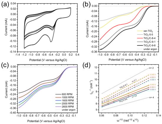
Figure 7.
(a) Cyclic voltammogram measured for TiO2/C-9-1 in O2-saturated 0.1 M KOH solution at a scan rate of 100 mV s−1. (b) Polarization curves measured in O2-saturated 0.1 M KOH solution, at a scan rate of 10 mV s−1, and a rotation rate of 1600 rpm for xer-TiO2, TiO2-5-5 and the TiO2/C-x-y series. (c) Polarization curves measured in O2-saturated 0.1 M KOH solution (solid lines) for TiO2/C-9-1 at different rotation rates from 600 to 2600 rpm, at a scan rate of 10 mV s−1. The dashed lines are the polarization curves measured in Ar-saturated 0.1 M KOH solution, at a scan rate of 10 mV s−1 and a rotation rate of 1600 rpm. (d) Koutecky–Levich plots obtained for TiO2/C-9-1 (colored dashed lines) and TiO2/C-9-8 (colored solid lines) at different voltages (from −0.45 to −0.55 V vs. Ag/AgCl). The dotted lines correspond to the ideal two electrons process (n = 2) and four electrons process (n = 4).
Table 2.
Electrochemical properties towards the ORR in 0.1 M KOH of xer-TiO2, TiO2-5-5 and the different TiO2/C-x-y samples studied herein. Comparison with a commercial Pt/C, 20 wt.%, catalyst.
To further investigate the electrocatalytic mechanisms involved herein, polarization curves were acquired at different rotation rates, from 600 to 2600 rpm (Figure 7c). The reciprocal current (IO2−1) was plotted against the reciprocal root of the angular rotation rate (ω−1/2) at various potentials from −0.3 to −0.55 V vs. Ag/AgCl, giving Koutecky–Levich (KL) plots (Figure 7d and Appendix A). These plots were drawn for TiO2/C-9-1 and TiO2/C-9-8. While the slope gives information about the electron transfer number, the y-intercept (equal to the reciprocal kinetic current) gives information about the kinetic current and the rate constant of the reaction [44]. As for kinetic currents, they are similar for TiO2/C-9-1 and TiO2/C-9-8, but lower than Pt/C, 20 wt.%, used as a benchmark (Table 2 and Appendix B, Figure A1). This result supports low rate constants for TiO2/C-9-1 and TiO2/C-9-8 as compared with Pt/C, 20 wt.%. As for electron transfer numbers, KL plots revealed a clear difference between the two TinO2n−1@TiO2/C nanocomposites. While TiO2/C-9-1 seems to be very selective for the two electrons process, TiO2/C-9-8 depicts an intermediary behavior between the two electrons process and the four electrons process (Figure 7d). While not fully understood, this difference may be attributed to enhanced electronic conductivity and charge transfer across the TiO2-carbon interface, due to the longer plateau duration at 950 °C during carbothermal reduction.
4. Discussion and Conclusions
Overall, the NHSG route allowed producing TinO2n−1@TiO2/C nanocomposites by a straightforward solvent-free, additive-free approach that meets the challenge of atom economy, as it merely involves TiCl4 and THF in stoichiometric amounts. Despite a theoretically sufficient C:Ti molar ratio, the carbothermal reduction, even after long treatment, was incomplete as compared with recent studies reported in literature [28,29,32]. NHSG routes usually yield highly condensed and well crystallized metal oxide particles [33], which is also true in the present case. Thus, one may assume that these native TiO2 anatase nanocrystals are more resistant to the carbothermal reduction, which was most probably limited here to the titanium atoms located at the very surface of the nanoparticles or to the smallest nanocrystals. Besides, the nature and the reactivity of the carbon produced by the NHSG route may also be a source of explanation of the incomplete carbothermal reduction, since it has been reported that the type of carbon plays an important role on the reducibility of TiO2 [58].
Anyway, the NHSG route seems promising and should be further explored. To better understand the mechanisms involved in the carbothermal reduction and to identify the key parameters, other NHSG routes, with various oxygen donors and carbon sources, should be considered to yield smaller nanocrystals and/or higher carbon contents. The use of innocuous alternatives to THF, such as polysaccharides [59], should be also investigated to make the whole procedure safer and more sustainable. Besides, alternative reduction protocols are currently considered to yield more advanced reduction reactions, such as higher temperatures, the use of hydrogen gas or the addition of oxygen scavengers. To conclude, we believe that these preliminary results will open a window of opportunity for the design of metal suboxides/carbon nanocomposites through atom-economic NHSG routes. This approach should not be limited to titanium suboxides and can easily be extended to other metal oxides.
Author Contributions
Conceptualization, N.B.; validation, R.B., P.H.M., and N.B.; investigation, S.Z.; writing—original draft preparation, N.B.; writing—review and editing, R.B., B.B., and P.H.M.; supervision, R.B. and N.B.; funding acquisition, P.H.M. and R.B. All authors have read and agreed to the published version of the manuscript.
Funding
This research was partially funded by the European Commission in the framework of POROUS4APP project (H2020 GA no. 666157).
Acknowledgments
Nicolas Brun is grateful to Angel Manuel Escamilla-Pérez for fruitful discussions. The authors would like to thank Franck Godiard for TEM and Erwan Oliviero for STEM-EDX.
Conflicts of Interest
The authors declare no conflict of interest.
Appendix A
Koutecky–Levich equation applied herein [44]:
where, I is the measured catalytic current; Ik is the kinetic current; n is the electron transfer number in half reaction; F is the Faraday constant, i.e., 96 485.34 C mol−1; A is the electrode surface area in cm2 (electrode diameter of 0.3 cm); υ is the kinematic viscosity of the electrolyte, i.e., 0.01 cm2 s−1 for KOH at 0.1 M; CO2 is the solubility of O2 in the electrolyte, i.e., 1.2 × 10⁻⁶ mol cm−3 in KOH 0.1 M; DO2 is the diffusion coefficient of O2 in the electrolyte, i.e., 1.9 × 10⁻⁵ cm2 s−1 in KOH 0.1 M at 25 °C; and ω is the angular rotation rate in rad s−1.
Appendix B

Figure A1.
(a) Polarization curves measured in O2-saturated 0.1 M KOH solution (solid lines) for Pt/C, 20 wt.%, at different rotation rates from 600 to 2600 rpm, at a scan rate of 10 mV s−1. The dashed line is the polarization curve measured in argon-saturated 0.1 M KOH solution, at a scan rate of 10 mV s−1 and a rotation rate of 1600 rpm. (b) Koutecky–Levich plots obtained for Pt/C, 20 wt.% (colored solid lines), at different voltages (from −0.45 to −0.55 V vs. Ag/AgCl). The dotted lines correspond to the ideal two electrons process (n = 2) and four electrons process (n = 4).

References
- Harada, S.; Tanaka, K.; Inui, H. Thermoelectric properties and crystallographic shear structures in titanium oxides of the Magneli phases. J. Appl. Phys. 2010, 108, 083703. [Google Scholar] [CrossRef]
- Padilha, A.C.M.; Osorio-Guillen, J.M.; Rocha, A.R.; Dalpian, G.M. TinO2n−1 Magneli phases studied using density functional theory. Phys. Rev. B 2014, 90, 035213. [Google Scholar] [CrossRef]
- Padilha, A.C.M.; Raebiger, H.; Rocha, A.R.; Dalpian, G.M. Charge storage in oxygen deficient phases of TiO2: Defect Physics without defects. Sci. Rep. 2016, 6, 28871. [Google Scholar] [CrossRef] [PubMed]
- Szot, K.; Rogala, M.; Speier, W.; Klusek, Z.; Besmehn, A.; Waser, R. TiO2-a prototypical memristive material. Nanotechnology 2011, 22, 254001. [Google Scholar] [CrossRef]
- Anderson, J.S.; Tilley, R.J.D. Crystallographic Shear in Oxygen-Deficient Rutile: An Electron Microscope Study. J. Solid State Chem. 1970, 2, 472–482. [Google Scholar] [CrossRef]
- Chen, X.B.; Liu, L.; Huang, F.Q. Black titanium dioxide (TiO2) nanomaterials. Chem. Soc. Rev. 2015, 44, 1861–1885. [Google Scholar] [CrossRef]
- Cho, E.; Han, S.; Ahn, H.S.; Lee, K.R.; Kim, S.K.; Hwang, C.S. First-principles study of point defects in rutile TiO2-x. Phys. Rev. B 2006, 73, 193202. [Google Scholar] [CrossRef]
- Andersson, S.; Collen, B.; Kuylenstierna, U.; Magneli, A. Phase Analysis Studies on the Titanium-Oxygen System. Acta Chem. Scand. 1957, 11, 1641–1652. [Google Scholar] [CrossRef]
- Andersson, S.; Collen, B.; Kruuse, G.; Kuylenstierna, U.; Magneli, A.; Pestmalis, H.; Asbrink, S. Identification of Titanium Oxides by X-Ray Powder Patterns. Acta Chem. Scand. 1957, 11, 1653–1657. [Google Scholar] [CrossRef]
- Asbrink, S.; Magneli, A. Crystal Structure Studies on Trititanium Pentoxide, Ti3O5. Acta Crystallogr. 1959, 12, 575–581. [Google Scholar] [CrossRef]
- Rajaraman, T.S.; Parikh, S.P.; Gandhi, V.G. Black TiO2: A review of its properties and conflicting trends. Chem. Eng. J. 2020, 389, 123918. [Google Scholar] [CrossRef]
- Bartholomew, R.F.; Frankl, D.R. Electrical Properties of Some Titanium Oxides. Phys. Rev. 1969, 187, 828–833. [Google Scholar] [CrossRef]
- Han, W.Q.; Zhang, Y. Magneli phases TinO2n−1 nanowires: Formation, optical, and transport properties. Appl. Phys. Lett. 2008, 92, 203117. [Google Scholar] [CrossRef]
- Niu, M.; Tan, H.Q.; Cheng, D.J.; Sun, Z.C.; Cao, D.P. Bandgap engineering of Magnei phase TinO2n−1: Electron-hole self-compensation. J. Chem. Phys. 2015, 143, 054701. [Google Scholar] [CrossRef] [PubMed]
- Feng, H.F.; Xu, Z.F.; Ren, L.; Liu, C.; Zhuang, J.C.; Hu, Z.P.; Xu, X.; Chen, J.; Wang, J.O.; Hao, W.C.; et al. Activating Titania for Efficient Electrocatalysis by Vacancy Engineering. ACS Catal. 2018, 8, 4288–4293. [Google Scholar] [CrossRef]
- Oturan, N.; Ganiyu, S.O.; Raffy, S.; Oturan, M.A. Sub-stoichiometric titanium oxide as a new anode material for electro-Fenton process: Application to electrocatalytic destruction of antibiotic amoxicillin. Appl. Catal. B-Environ. 2017, 217, 214–223. [Google Scholar] [CrossRef]
- Pei, D.N.; Gong, L.; Zhang, A.Y.; Zhang, X.; Chen, J.J.; Mu, Y.; Yu, H.Q. Defective titanium dioxide single crystals exposed by high-energy {001} facets for efficient oxygen reduction. Nat. Commun. 2015, 6, 8696. [Google Scholar] [CrossRef]
- Yao, C.H.; Li, F.; Li, X.; Xia, D.G. Fiber-like nanostructured Ti4O7 used as durable fuel cell catalyst support in oxygen reduction catalysis. J. Mater. Chem. 2012, 22, 16560–16565. [Google Scholar] [CrossRef]
- Massazza, D.; Parra, R.; Busalmen, J.P.; Romeo, H.E. New ceramic electrodes allow reaching the target current density in bioelectrochemical systems. Energ. Environ. Sci. 2015, 8, 2707–2712. [Google Scholar] [CrossRef]
- Domaschke, M.; Zhou, X.M.; Wergen, L.; Romeis, S.; Miehlich, M.E.; Meyer, K.; Peukert, W.; Schmuki, P. Magneli-Phases in Anatase Strongly Promote Cocatalyst-Free Photocatalytic Hydrogen Evolution. ACS Catal. 2019, 9, 3627–3632. [Google Scholar] [CrossRef]
- Hamad, H.; Bailon-Garcia, E.; Maldonado-Hodar, F.J.; Perez-Cadenas, A.F.; Carrasco-Marin, F.; Morales-Torres, S. Synthesis of TixOy nanocrystals in mild synthesis conditions for the degradation of pollutants under solar light. Appl. Catal. B-Environ. 2019, 241, 385–392. [Google Scholar] [CrossRef]
- An, X.Q.; Hu, C.Z.; Liu, H.J.; Qu, J.H. Oxygen vacancy mediated construction of anatase/brookite heterophase junctions for high-efficiency photocatalytic hydrogen evolution. J. Mater. Chem. A 2017, 5, 24989–24994. [Google Scholar] [CrossRef]
- Negi, S.S. Enhanced light harvesting and charge separation over wormhole mesoporous TiO2−x nanocrystallites towards efficient hydrogen generation. Sustain. Energ. Fuels 2019, 3, 1191–1200. [Google Scholar] [CrossRef]
- Tao, X.Y.; Wang, J.G.; Ying, Z.G.; Cai, Q.X.; Zheng, G.Y.; Gan, Y.P.; Huang, H.; Xia, Y.; Liang, C.; Zhang, W.K.; et al. Strong Sulfur Binding with Conducting Magneli-Phase TinO2n−1 Nanomaterials for Improving Lithium-Sulfur Batteries. Nano Lett. 2014, 14, 5288–5294. [Google Scholar] [CrossRef] [PubMed]
- Wei, H.; Rodriguez, E.F.; Best, A.S.; Hollenkamp, A.F.; Chen, D.H.; Caruso, R.A. Chemical Bonding and Physical Trapping of Sulfur in Mesoporous Magneli Ti4O7 Microspheres for High- Performance Li-S Battery. Adv. Energy Mater. 2017, 7, 1601616. [Google Scholar] [CrossRef]
- Kitada, A.; Hasegawa, G.; Kobayashi, Y.; Kanamori, K.; Nakanishi, K.; Kageyama, H. Selective Preparation of Macroporous Monoliths of Conductive Titanium Oxides TinO2n−1 (n = 2, 3, 4, 6). J. Am. Chem. Soc. 2012, 134, 10894–10898. [Google Scholar] [CrossRef]
- Azor-Lafarga, A.; Ruiz-Gonzalez, L.; Parras, M.; Portehault, D.; Sanchez, C.; Gonzalez-Calbet, J.M. Modified Synthesis Strategies for the Stabilization of low n TinO2n-1 Magneli Phases. Chem. Rec. 2018, 18, 1105–1113. [Google Scholar] [CrossRef]
- Portehault, D.; Maneeratana, V.; Candolfi, C.; Deschler, N.; Veremchuk, I.; Grin, Y.; Sanchez, C.; Antonietti, M. Facile General Route toward Tunable Magneli Nanostructures and Their Use As Thermoelectric Metal Oxide/Carbon Nanocomposites. ACS Nano 2011, 5, 9052–9061. [Google Scholar] [CrossRef]
- Huang, S.S.; Lin, Y.H.; Chuang, W.; Shao, P.S.; Chuang, C.H.; Lee, J.F.; Lu, M.L.; Weng, Y.T.; Wu, N.L. Synthesis of High-Performance Titanium Sub-Oxides for Electrochemical Applications Using Combination of Sol-Gel and Vacuum-Carbothermic Processes. ACS Sustain. Chem. Eng. 2018, 6, 3162–3168. [Google Scholar] [CrossRef]
- Tominaka, S.; Tsujimoto, Y.; Matsushita, Y.; Yamaura, K. Synthesis of Nanostructured Reduced Titanium Oxide: Crystal Structure Transformation Maintaining Nanomorphology. Angew. Chem. Int. Edit. 2011, 50, 7418–7421. [Google Scholar] [CrossRef]
- Kitada, A.; Hasegawa, G.; Kobayashi, Y.; Miyazaki, K.; Abe, T.; Kanamori, K.; Nakanishi, K.; Kageyama, H. Hierarchically Porous Monoliths of Oxygen-deficient Anatase TiO2−x with Electronic Conductivity. RSC Adv. 2013, 3, 26475. [Google Scholar] [CrossRef]
- Mei, S.L.; Jafta, C.J.; Lauermann, I.; Ran, Q.; Kargell, M.; Ballauff, M.; Lu, Y. Porous Ti4O7 Particles with Interconnected-Pore Structure as a High-Efficiency Polysulfide Mediator for Lithium-Sulfur Batteries. Adv. Funct. Mater. 2017, 27, 1701176. [Google Scholar] [CrossRef]
- Mutin, P.H.; Vioux, A. Recent advances in the synthesis of inorganic materials via non-hydrolytic condensation and related low-temperature routes. J. Mater. Chem. A 2013, 1, 11504–11512. [Google Scholar] [CrossRef]
- Niederberger, M.; Garnweitner, G. Organic reaction pathways in the nonaqueous synthesis of metal oxide nanoparticles. Chem. Eur. J. 2006, 12, 7282–7302. [Google Scholar] [CrossRef] [PubMed]
- Debecker, D.P.; Hulea, V.; Mutin, P.H. Mesoporous mixed oxide catalysts via non-hydrolytic sol-gel: A review. Appl. Catal. A Gen. 2013, 451, 192–206. [Google Scholar] [CrossRef]
- Pinna, N.; Niederberger, M. Surfactant-free nonaqueous synthesis of metal oxide nanostructures. Angew. Chem. Int. Edit. 2008, 47, 5292–5304. [Google Scholar] [CrossRef]
- Deshmukh, R.; Niederberger, M. Mechanistic Aspects in the Formation, Growth and Surface Functionalization of Metal Oxide Nanoparticles in Organic Solvents. Chem. Eur. J. 2017, 23, 8542–8570. [Google Scholar] [CrossRef] [PubMed]
- Niederberger, M.; Garnweitner, G.; Pinna, N.; Neri, G. Non-aqueous routes to crystalline metal oxide nanoparticles: Formation mechanisms and applications. Prog. Solid State Chem. 2005, 33, 59–70. [Google Scholar] [CrossRef]
- Niederberger, M. Nonaqueous sol-gel routes to metal oxide nanoparticles. Acc. Chem. Res. 2007, 40, 793–800. [Google Scholar] [CrossRef]
- Hay, J.N.; Raval, H.M. Synthesis of organic-inorganic hybrids via the non-hydrolytic sol-gel process. Chem. Mater. 2001, 13, 3396–3403. [Google Scholar] [CrossRef]
- Wang, Y.H.; Alauzun, J.G.; Mutin, P.H. Water-Stable, Nonsiliceous Hybrid Materials with Tunable Porosity and Functionality: Bridged Titania-Bisphosphonates. Chem. Mater. 2020, 32, 2910–2918. [Google Scholar] [CrossRef]
- Escamilla-Perez, A.M.; Louvain, N.; Boury, B.; Brun, N.; Mutin, P.H. Ethers as Oxygen Donor and Carbon Source in Non-hydrolytic Sol-Gel: One-Pot, Atom-Economic Synthesis of Mesoporous TiO2-Carbon Nanocomposites. Chem. Eur. J. 2018, 24, 4982–4990. [Google Scholar] [CrossRef] [PubMed]
- Han, X.Y.; Russo, P.A.; Goubard-Bretesche, N.; Patane, S.; Santangelo, S.; Zhang, R.; Pinna, N. Exploiting the Condensation Reactions of Acetophenone to Engineer Carbon-Encapsulated Nb2O5 Nanocrystals for High-Performance Li and Na Energy Storage Systems. Adv. Energy Mater. 2019, 9, 1902813. [Google Scholar] [CrossRef]
- Masa, J.; Batchelor-McAuley, C.; Schuhmann, W.; Compton, R.G. Koutecky-Levich analysis applied to nanoparticle modified rotating disk electrodes: Electrocatalysis or misinterpretation? Nano Res. 2014, 7, 71–78. [Google Scholar] [CrossRef]
- Escamilla-Perez, A.M.; Louvain, N.; Kaschowitz, M.; Freunberger, S.; Fontaine, O.; Boury, B.; Brun, N.; Mutin, P.H. Lithium insertion properties of mesoporous nanocrystalline TiO2 and TiO2-V2O5 microspheres prepared by non-hydrolytic sol-gel. J. Sol-Gel Sci. Technol. 2016, 79, 270–278. [Google Scholar] [CrossRef]
- Nolan, N.T.; Seery, M.K.; Pillai, S.C. Spectroscopic Investigation of the Anatase-to-Rutile Transformation of Sol-Gel-Synthesized TiO2 Photocatalysts. J. Phys. Chem. C 2009, 113, 16151–16157. [Google Scholar] [CrossRef]
- Tsumura, T.; Kojitani, N.; Izumi, I.; Iwashita, N.; Toyoda, M.; Inagaki, M. Carbon coating of anatase-type TiO2 and photoactivity. J. Mater. Chem. 2002, 12, 1391–1396. [Google Scholar] [CrossRef]
- Escamilla-Pérez, A.M. Non-hydrolytic sol-gel synthesis of TiO2-based electrode materials for Li-ion batteries. Ph.D. Thesis, University Montpellier, Montpellier, France, September 2018. [Google Scholar]
- Thommes, M. Physical Adsorption Characterization of Nanoporous Materials. Chem. Ing. Tech. 2010, 82, 1059–1073. [Google Scholar] [CrossRef]
- Dai, L.M.; Xue, Y.H.; Qu, L.T.; Choi, H.J.; Baek, J.B. Metal-Free Catalysts for Oxygen Reduction Reaction. Chem. Rev. 2015, 115, 4823–4892. [Google Scholar] [CrossRef]
- Shao, M.H.; Chang, Q.W.; Dodelet, J.P.; Chenitz, R. Recent Advances in Electrocatalysts for Oxygen Reduction Reaction. Chem. Rev. 2016, 116, 3594–3657. [Google Scholar] [CrossRef]
- Ge, X.M.; Sumboja, A.; Wuu, D.; An, T.; Li, B.; Goh, F.W.T.; Hor, T.S.A.; Zong, Y.; Liu, Z.L. Oxygen Reduction in Alkaline Media: From Mechanisms to Recent Advances of Catalysts. ACS Catal. 2015, 5, 4643–4667. [Google Scholar] [CrossRef]
- Li, Y.G.; Dai, H.J. Recent advances in zinc-air batteries. Chem. Soc. Rev. 2014, 43, 5257–5275. [Google Scholar] [CrossRef] [PubMed]
- Ramaswamy, N.; Mukerjee, S. Alkaline Anion-Exchange Membrane Fuel Cells: Challenges in Electrocatalysis and Interfacial Charge Transfer. Chem. Rev. 2019, 119, 11945–11979. [Google Scholar] [CrossRef] [PubMed]
- Brun, N.; Wohlgemuth, S.A.; Osiceanu, P.; Titirici, M.M. Original design of nitrogen-doped carbon aerogels from sustainable precursors: Application as metal-free oxygen reduction catalysts. Green Chem. 2013, 15, 2514–2524. [Google Scholar] [CrossRef]
- Pham-Truong, T.N.; Petenzi, T.; Ranjan, C.; Randriamahazaka, H.; Ghilane, J. Microwave assisted synthesis of carbon dots in ionic liquid as metal free catalyst for highly selective production of hydrogen peroxide. Carbon 2018, 130, 544–552. [Google Scholar] [CrossRef]
- Appel, A.M.; Helm, M.L. Determining the Overpotential for a Molecular Electrocatalyst. ACS Catal. 2014, 4, 630–633. [Google Scholar] [CrossRef]
- Jha, A.; Yoon, S.J. Formation of titanium carbonitride phases via the reduction of TiO2 with carbon in the presence of nitrogen. J. Mater. Sci. 1999, 34, 307–322. [Google Scholar] [CrossRef]
- Kim, S.; De Bruyn, M.; Alauzun, J.G.; Louvain, N.; Brun, N.; Macquarrie, D.J.; Stievano, L.; Mutin, P.H.; Monconduit, L.; Boury, B. Dehydration of Alginic Acid Cryogel by TiCl4 vapor: Direct Access to Mesoporous TiO2@C Nanocomposites and Their Performance in Lithium-Ion Batteries. Chemsuschem 2019, 12, 2660–2670. [Google Scholar] [CrossRef]


© 2020 by the authors. Licensee MDPI, Basel, Switzerland. This article is an open access article distributed under the terms and conditions of the Creative Commons Attribution (CC BY) license (http://creativecommons.org/licenses/by/4.0/).