Abstract
Co3+ doping in BiFeO3 is expected to be an effective method for improving its magnetic properties. In this work, pristine BiFeO3 (BFO) and doped BiFe1-xCoxO3 (BFCxO, x = 0.01, 0.03, 0.05, 0.07 and 0.10) composite thin films were successfully synthesized by a sol–gel technique. XRD and Raman spectra indicate that the Co3+ ions are substituted for the Fe3+ ion sites in the BFO rhombohedral lattice. Raman vibration of oxygen octahedron is obviously weakened due to the lattice distortion induced by the size mismatch between two B-site cations (Fe3+ and Co3+ ions), which has an impact on the magnetic properties of BFCxO. SEM images reveal a denser agglomeration in Co-doped samples. TEM results indicate that the average size of grains is reduced due to the Co3+ substitution. XPS measurements illustrate that the replacement of Fe3+ with Co3+ effectively suppresses the generation of oxygen defects and increases the concentration of Fe3+ ions at the B-site of perovskite lattice. Vibrating sample magnetometer (VSM) measurements show that the remanent magnetization (Mr) of BFC0.07O (3.6 emu/cm3) and the saturation magnetization (Ms) of BFC0.10O (48.84 emu/cm3) thin film both increase by approximately two times at room temperature, compared with that of the pure BFO counterpart.
1. Introduction
Recently, magnetoelectric and multiferroic materials have attracted considerable attention due to their abundant physical properties and potential applications in sensors, spintronic devices, memory devices, magnetoelectric devices, capacitors, nonvolatile logic, etc. [1,2]. BiFeO3 (BFO), a kind of single crystal multiferroic material, is one of the most well-known compounds of ABO3 perovskite, and its G-type structure shows both (anti-) ferromagnetism and ferroelectricity at room temperature [2,3]. BFO always crystallizes with the rhombohedral structure (space group, R3c) where Bi3+ ions occupy the A-site and Fe3+ ions occupy the B-site in the distorted perovskite lattice [4,5]. It has been reported that the super-exchange interaction between Fe3p and O2p ions plays an important role in the ferromagnetic properties of BFO. The ferroelectric properties stem from the off-center displacement of 6s2 lone pair electrons of Bi3+ ions [6,7]. Meanwhile, the potential magnetoelectric coupling effect in BFO has also attracted much attention [8,9]. However, BFO always shows a long-range spin cycloid structure (Figure 1) because the impurity phases (such as Bi2Fe4O9, Bi24FeO40, etc.) are mixed in its rhombohedral phase, thus limiting its potential applications [10,11]. Therefore, great efforts have been made to improve the structures and properties of BFO by means of ions doping, such as A-site doping rare-earth (Er3+, La3+, Sm3+ and Ho3+, etc.) or divalent alkaline-earth metal ions (Ba2+, Ca2+, Sr2+, etc.), B-site doping transition metal ions (Cr3+, Mn4+, Ti4+, etc.) and A–B-site co-doping (Ho–Mn, Ce–Zr, Sm–Zr, etc.) [9,10,11,12,13,14,15,16,17].
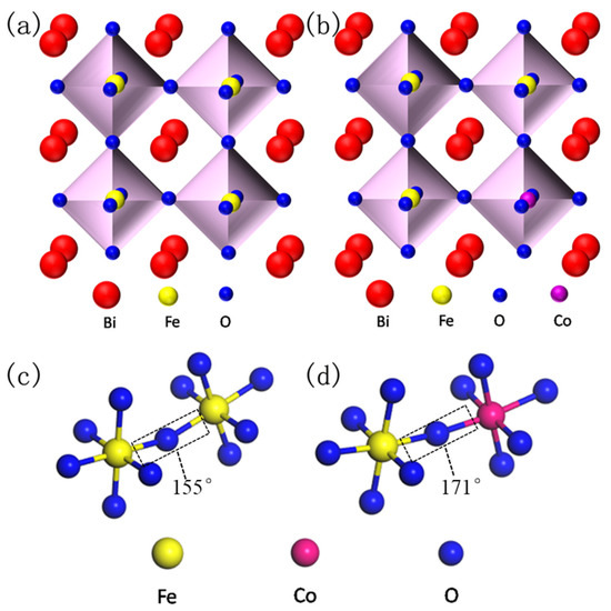
Figure 1.
Simulated crystal structure of perovskite BiFeO3 (BFO) (a) and Co substitution BFO (b), and the corresponding super-exchange interaction of Fe–O–Fe (c) and Fe–O–Co (d).
Trivalent cobalt (Co3+) is a typical transition metal ion with favorable magnetic activity. The effective doping of Co3+ ions in ferroelectric materials is of great significance for their applications in multiferroic memory devices [17,18]. In this work, BiFe1-xCoxO3 (x = 0.00–0.10) (BFCxO) thin films were synthesized on the Si substrates by the sol–gel technique. The structures, surface morphologies, and magnetic properties of BiFe1-xCoxO3 (x = 0.00–0.10) thin films were established by the XRD, XPS, Raman, SEM, TEM and vibrating sample magnetometer (VSM). In particular, the magnetic properties of doped BFCxO thin films were significantly improved compared with those of the pristine BFO counterpart. The underlying reasons for the enhanced magnetic properties were also investigated and discussed.
2. Experimental Details
Pure BiFeO3 (BFO) and BiFe1-xCoxO3 (BFCxO, x = 0.01, 0.03, 0.05, 0.07 and 0.10) composite thin films were fabricated on Si substrates via the sol–gel technique. High-purity bismuth nitrate [Bi(NO3)3·5H2O] (Shanghai, China), ferric nitrate [Fe(NO3)3·9H2O] (Shanghai, China) and Cobalt(II) nitrate hexahydrate [Co(NO3)2·6H2O] (Shanghai, China) were used as the starting materials. These agents were mixed with ethylene glycol in a specific ratio and stirred thoroughly until clarified. After aging for 24 h, a homogeneous precursor solution of 0.2 mol/L was obtained. The uniform precursor solution grew on an impurity-free silicon substrate via the spin-casting method. The spin-coating process was divided into two steps of 500 rpm for 3 s and 4000 rpm for 20 s, and subsequently, the wet homogeneous films were pre-annealed at 350 °C for 6 min. The above-mentioned process was repeated by spin-coating each layer to obtain a semi-finished film of moderate thickness. Finally, all semi-finished samples were crystallized in air at 500 °C for 1 h and then cooled to room temperature to obtain perfect thin films. The diagram of the experimental procedure is shown in Figure 2.
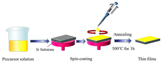
Figure 2.
Diagram of the preparation process for pure BiFeO3 (BFO) and BiFe1-xCoxO3 (BFCxO, x = 0.01, 0.03, 0.05, 0.07 and 0.10) composite thin films.
The structural characteristics and phase purity of all thin films were analyzed by X-ray diffraction patterns (XRD) (XRD, Rigaku Corporation, Tokyo, Japan) at room temperature using Cu Kαradiation (40 kV, 200 mA). The surface morphologies of these samples and the thickness of cross-sections were characterized by the field emission scanning electron microscopy (FESEM) (Hitachi S-4800, JEOL Ltd., Tokyo, Japan) Model Hitachi, S-570. The interplanar spacing of the samples was investigated by transmission electron microscope (TEM, 200 keV, JEM-2100HR, JEOL Ltd., Tokyo, Japan). A Lake Shore 7407 vibrating sample magnetometer (VSM) (VSM, Lake Shore, Columbus, OH, USA) was used to investigate the magnetic hysteresis (M–H) loops of the samples at room temperature. Raman spectra were measured by a Renishaw MicroRaman spectrometer (Renishaw, London, UK) equipped with an Ar ion laser excitation at 514 nm. X-ray photoelectron spectra (XPS) were conducted via A1 Ka line by using a Thermo Scientific ESCALAB 250Xi A1440 system (XPS, Thermo Fisher Scientific, Waltham, MA, USA).
3. Results and Discussion
In order to facilitate the understanding about the doping principle and super-exchange interaction of BFO, the crystal structures of pure BFO and doped BFCxO are simulated as seen in Figure 1a–d. As is commonly known, the BFO composite thin film possesses a distorted rhombohedral perovskite structure (space group R3c). FeO6 octahedron is composed of iron ions at the center and six oxygen ions in the surrounding areas. Additionally, bismuth ions (the apex position) form a cube in which FeO6 octahedron is embedded. Fe3+ ions occupy the center of the body and oxygen ions occupy the center of the surface. In Co3+-doped BFO thin films, two adjacent FeO6/CoO6 octahedrons are linked by sharing one oxygen anion [19]. Doping Co3+ ions will lead to the random replacement of some Fe3+ ions at B-site, thus inhibiting the generation of the spin cycloid spiral modulation structure due to the size effect and chemical strain effect caused by the size mismatch of the two B-site cations (Fe3+ and Co3+ ions) [20]. Figure 1c,d clearly illustrates that Co ions successfully replace Fe ions and form high-energy Co–O bonds, leading to an increase in the inclination angle of the super-exchange interaction [21]. The super-exchange interaction of Fe–O–Fe (or Co) is improved, which is beneficial to enhancing the magnetic properties of BFCxO (see details below).
Figure 3a,b shows the X-ray diffraction (XRD) patterns of the BiFe1-xCoxO3 (BFCxO, x = 0.00, 0.01, 0.03, 0.05, 0.07 and 0.10) thin films. The diffraction peaks of all the samples are completely consistent with the standard XRD pattern of the rhombohedral phase (space group R3c) (JCPDS # 71-2494). Meanwhile, a weak XRD peak of impurity is found at 28.8° corresponding to Bi2Fe4O9 [17,21]. Bi2Fe4O9 will have no significant impact on the intrinsic structures and properties of BFCxO because it is paramagnetic and its content is relatively small in the samples [17,21]. Figure 3b shows magnified XRD patterns of Co substituted thin films at different concentrations in the vicinity of 2θ = 32°. Obviously, the diffraction peaks of (104) and (110) move at higher angles with the increase of Co3+ concentration, indicating that the Co ions have been successfully positioned in the host lattice of BFO. The radius of Co3+ ions is smaller than that of Fe3+ ions, which will lead to lattice contraction and structural distortion.
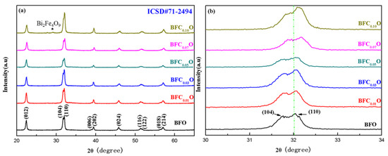
Figure 3.
(a) XRD patterns of BFO and BFCxO thin films, and (b) correspondingly magnified patterns around 32°.
To further investigate the structural changes of all thin films with doping concentrations, we carried out Raman spectra measurements on BFO and BFCxO thin films, as shown in Figure 4. According to group theory, BFO displays 13 optical-phonon active modes (4A1 + 9E) with space group R3c [22,23]. The 4 modes at 149.6, 170.0, 217.6 and 436.1 cm−1 can be designated as A1–symmetry longitudinal optical modes [A1-1, A1-2, A1-3, A1-4 (LO)], and 8 modes at 77.0, 265.6, 318.7, 345.4, 369.2, 482.3, 515.6 and 617.8 cm−1 are associated with transverse optical E(TO) (E-1, E-2, E-3, E-5, E-6, E-7, E-8, E-9 (TO)) phonons [24,25]. In this work, the E-8 mode of BFO thin film overlaps with the Raman vibration mode of silicon substrate. The results of first-principles calculation have revealed that the Bi-O vibrations only participate in the low-frequency region of the A1 modes and the Fe–O vibrations mainly participate in the high-frequency region of the E modes [24,25,26,27]. Compared with that of pure BFO, the peak positions of Raman spectra of BFCxO are slightly red-shifted, and the intensity decreases as Co doping concentration increases. Among them, the weakening of A1-2 and A1-3 modes is due to the relatively weak Bi 6s2 lone pair electrons in the doped BFCxO thin films in stereochemistry, which also indicates that the Co ions are successfully located into the BFO lattice. The high-frequency modes are mainly attributed to the vibration of FeO6 octahedron. When the Fe sites are occupied by Co3+ ions, Co3+ ions cannot completely fill the space of Fe3+ ions due to the size mismatch. Therefore, the oxygen octahedrons are greatly distorted by the Jahn–Teller effect [28,29]. This is caused by the change in Fe–O bonds and accounts for the enhanced magnetic properties to be described as follows.
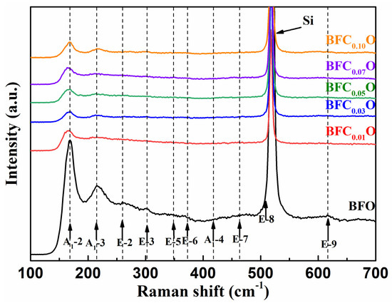
Figure 4.
Raman spectra of BFO and BFCxO thin films at room temperature.
The SEM images of surface and cross-section of BFCxO thin films are shown in Figure 5a–f. It can be seen that the Co-substituted thin films not only show a homogeneous surface morphology and conspicuous agglomeration, but also attach well to the silicon substrates without obvious separation. Additionally, the cross-sectional thickness of BFCxO thin films is 308, 293, 288, 261, 223 and 221 nm, respectively. With the increase of Co doping concentration, the thickness obviously decreases, indicating that Co doping makes the surface uniformly dense and grain size decreases [26,27]. The grain size histogram and Gaussian fitting also prove that the grain size decreases with the increase of the Co concentration, as shown in Figure 6. It is also caused by the smaller radius of the Co ions, and correspondingly, the lattice collapses and oxygen vacancies are formed [26,27,28,29]. The suppression of oxygen vacancy concentration will slow down the movement of oxygen ions and the growth rate of crystal grains, thus reducing the size of crystal grains [26].
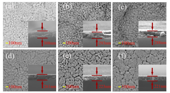
Figure 5.
SEM images of surface and cross-sectional morphologies of (a) BFO, (b) BFC0.01O, (c) BFC0.03O, (d) BFC0.05O, (e) BFC0.07O and (f) BFC0.10O thin films.
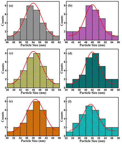
Figure 6.
Histograms for particle size distribution and Gaussian fitting curve of (a) BFO, (b) BFC0.01O, (c) BFC0.03O, (d) BFC0.05O, (e) BFC0.07O and (f) BFC0.10O thin films.
Figure 7 shows the typical TEM and HRTEM images of BFO and BFC0.05O thin films. The grain size is reduced slightly with the doping of Co3+ ions, which is consistent with the results of SEM images. The HRTEM images are shown in the inset of Figure 7, which are derived from the region within the circle. The lattice spacing of the typical crystalline region is about 0.407 and 0.401 nm, respectively, which is in good agreement with the (012) lattice plane of pure BFO (#71-2494).
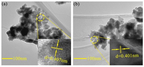
Figure 7.
Typical TEM images of (a) BFO and (b) BFC0.05O thin film. The insets are high resolution TEM images of BFO and BFC0.05O thin film.
The Bi4f, Fe2p, O1s and Co2p peaks of BFC0.01O and BFC0.07O thin films were measured and analyzed by XPS, as shown in Figure 8a–h. The difference in energy between Bi4f7/2 and Bi4f5/2 in Figure 8a,b is 5.3 eV, which is a standard value of Bi–O bonding. Figure 8c,d shows the Fe2p peaks of BFC0.01O and BFC0.07O thin films, respectively. The Fe2p3/2 peak position of BFC0.01O and BFC0.07O thin films is 710.06 and 710.11 eV, respectively, both of which are within the reasonable range (710.06–711.2 eV) [26,27]. The peak positions of Fe2p1/2 are 723.6 and 723.7 eV, respectively. The difference in binding energy (Spin-orbit splitting energy) between Fe2p3/2 and Fe2p1/2 peaks is 13.0 and 13.6 eV, respectively, agreeing well with the standard value of 13.6 eV [30]. The Fe2p3/2 and Fe2p1/2 peaks are fitted by two portions of Fe3+ ions and Fe2+ ions, and the ratios of Fe3+/Fe2+ of the BFC0.01O and BFC0.07O film samples are determined to be 0.57 and 1.59, respectively, indicating that there are more Fe3+ ions in the samples [28,29,30]. A satellite peak is found at the binding energy of 718.6 eV in Figure 8d, which is mainly related to the oxidation state of Fe and is determined by the difference in binding energy between the satellite peak and the 2p3/2 principal peak (Fe2+ ~ 6 eV, Fe3+ ~ 8 eV) [30,31,32,33]. The difference in binding energy between them is greater than 8 eV, indicating that the valence state of Fe is mainly +3 valences in the BFC0.07O sample [30,31,32,33]. Therefore, Co doping is expected to suppress the formation of Fe2+ ions in BFCxO, thereby improving the magnetic properties [29,30,31,32]. Due to the application of the sol–gel technique, Figure 8e,f shows the unavoidable O1s XPS spectra of oxygen vacancies. The O1s XPS peak is divided into two distinct peaks, which correspond to O2− ions in the X–O bonds and O defects in the structure, respectively [32,33]. The oxygen vacancy concentrations (O defects/O2− ions ratio) of BFC0.01O and BFC0.07O thin films significantly decrease from 0.48 to 0.37, suggesting that Co doping can restrain the formation of oxygen defects, which is consistent with previously reported results [32,33]. As seen in Figure 8g,h, the binding energy values of the Co2p3/2 XPS spectra are observed at 781.94 and 781.6 eV, corresponding to the standard peak positions of Co3+ ions [34].
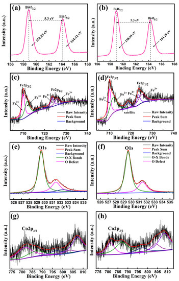
Figure 8.
XPS spectra of the as-annealed BFC0.01O thin films in the binding energy regions of (a) Bi4f, (c) Fe2p, (e) O1s and (g) Co2p; XPS spectra of the as-annealed BFC0.07O thin films in the binding energy regions of (b) Bi4f, (d) Fe2p, (f) O1s and (h) Co2p.
In order to explore the impact of Co doping on the magnetic properties at room temperature, we carried out the VSM measurements on BFO and BFCxO thin films in the magnetic field from 0 to 10 k Oe. The saturated magnetic hysteresis (M–H) loops of BFO and Co-doped thin films are shown in Figure 9a–f. With the increase of the Co doping concentration, the values of both saturation magnetization (Ms) and remanent magnetization (Mr) significantly increased. The values of Ms and Mr for BFO, BFC0.01O, BFC0.03O, BFC0.05O, BFC0.07O and BFC0.10O are 21.38 and 2.06, 25.57 and 2.40, 34.17 and 2.60, 34.48 and 3.00, 42.38 and 3.60, and 48.84 and 3.43 emu/cm3, respectively. The changes of Ms and Mr with the Co doping concentration are shown in Figure 10. Ms always increases linearly but Mr increases first and then decreases with the increase of Co3+ concentration over x = 0.10. The maximum value of Mr is 3.60 emu/cm3 when the concentration of doped Co is 0.07. Additionally, the maximum value of Ms is 48.84 emu/cm3 as the doping concentration is up to 0.10. According to the Goldschmidt tolerance factor t [26,27,28,29],
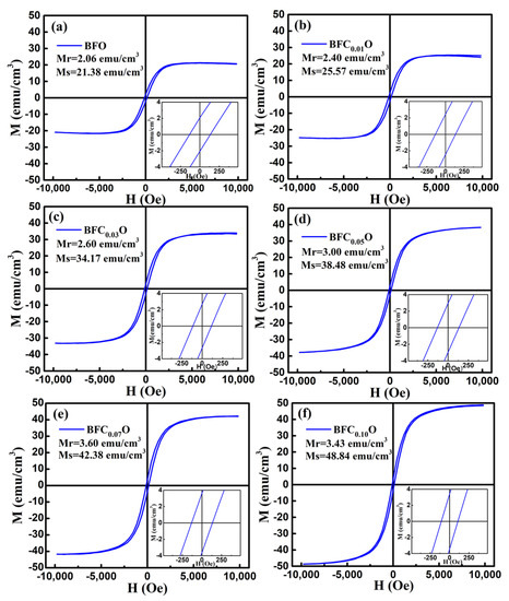
Figure 9.
The magnetic hysteresis (M–H) loops for (a) BFO, (b) BFC0.01O, (c) BFC0.03O, (d) BFC0.05O, (e) BFC0.07O and (f) BFC0.10O thin film at room temperature.
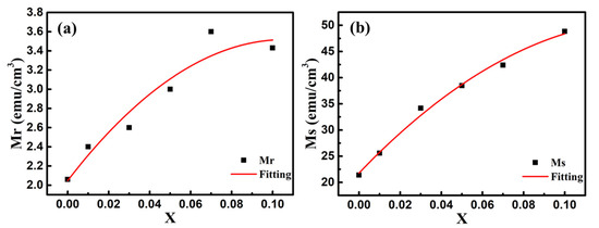
Figure 10.
The changes of (a) remanent magnetization (Mr) and (b) saturation magnetization (Ms) values with Co doping concentration. Red lines are the simulated results according to the binomial polynomial equation.
With the increase of the Co doping concentration, the tolerance factor becomes smaller and less than the unity. This will cause the shrinkage strain of the Fe–O bond, thus increasing the bond angle of FeO6 octahedron and increasing the degree of distortion between two adjacent octahedrons [26,27,28,29,33]. In the first principle, the inclination of the Fe3+ ions spins can be derived from the formula of the Dzyaloshinskii–Moriya (DM) [33,34] interaction energy of Fe3+ ions (HDM), which is defined as follows:
where is the interaction parameter, is the microscopic constant [33,34] and , are the position vectors of the nearest neighbor magnetic ions from the nth O ions to the nearest magnetic Fe ions. and are the vectors of the magnetic moments of two Fe ions [34,35]. In an ideal perovskite structure, the bond angle () of Fe–O–Fe is 180°, so the value of is zero, as is the value of . When begins to deflect from the ideality of 180°, the anti-symmetric exchange energy term will increase. In summary, several possible factors may account for the enhancement of magnetic properties for Co-doped BFCxO thin films: (i) an increased Fe–O–Fe spin angle results in the net macroscopic magnetization [25,36,37,38]; (ii) the suppression of the spin cycloid spiral modulation structures will release magnetism [25,26,27,28,29,39]; (iii) enhanced ferromagnetic properties are attributed to the super-exchange interaction between both d6 and d5 electronic configurations of Co3+ and Fe3+ [25,26,27,28,29,39]; (iv) Fe3+ ions are randomly replaced by Co3+ ions, resulting in the non-compensation of the spins on the surface of grains and making grain size closer to or less than the cycloidal modulation wavelength of ~62 nm [25,26,27,28,29,39,40,41,42]. Accordingly, it is an important way to improve the magnetic behavior of BFO thin films, which is beneficial for the application in subminiature devices and information storage.
4. Conclusions
In this work, a series of Co-doped BFO thin films were successfully prepared via a facile sol–gel technique. The relationships of structures, surficial morphologies, as well as magnetic properties of the samples were systematically studied. XRD and Raman spectra confirm that all samples are the rhombohedral perovskite structure and Co3+ ions are successfully positioned to the host lattice of BFO. SEM and TEM images suggest that a Co doping agent is beneficial for the uniformity of particle formation and the decrease of grain size. The surfaces of Co substitution thin films are attached to a few conspicuous agglomerations with a smaller grain size, which are beneficial for the magnetism release. XPS analysis illustrates that the replacement of Fe3+ ions with Co3+ ions can suppress the generation of oxygen defects and increase the concentration of Fe3+ ions occupying the B-site of perovskite lattice. VSM measurements indicate that the magnetic properties can be improved significantly and the maximum values of Mr and Ms are 3.60 and 48.84 emu/cm3, respectively, belonging to BFC0.07O and BFC0.10O thin films. The obvious enhancements of Ms and Mr mainly derive from the decrease of oxygen defects concentration, the denser agglomerations, the enhanced super-exchange interaction and the breakdown of spiral spin structure. These results demonstrate that Co3+ doping in BFO thin films is an effective method to improve their magnetic characteristics. Co-doped BFO thin films should have better application prospects in multiferroic memory devices, information storage and magnetic switch devices at room temperature.
Author Contributions
Conceptualization, M.S. and W.M.; Data curation, J.Z.; Funding acquisition, J.Y.; Project administration, Y.L.; Supervision, J.Z.; Writing—original draft, L.B.; Writing—review & editing, L.B. All authors have read and agree to the published version of the manuscript.
Funding
This work was supported by Natural Science Foundation of China (11904128), the Thirteenth Five-Year Program for Science and Technology of the Education Department of Jilin Province (JJKH20200409KJ), the Capital Construction Funds of Jilin Province (2020C029-5), the 2018 Provincial Talent Development Fund Funded Talent Project of Jilin Province (Research on Doping Modification Design, Preparation and Performance Improvement of Single-phase Multiferroic Materials BFO Film) and the United Laboratory of High Pressure Physics and Earthquake Science.
Conflicts of Interest
The authors declare no conflict of interest.
References
- Wu, J.; Fan, Z.; Xiao, D.; Zhu, J.; Wang, J. Multiferroic bismuth ferrite-based materials for multifunctional applications: Ceramic bulks, thin films and nanostructures. Prog. Mater. Sci. 2016, 84, 335–402. [Google Scholar] [CrossRef]
- Eerenstein, W.; Mathur, N.; Scott, J.F. Multiferroic and magnetoelectric materials. Nature 2006, 442, 759–765. [Google Scholar] [CrossRef] [PubMed]
- Spaldin, N.A. MATERIALS SCIENCE: The Renaissance of Magnetoelectric Multiferroics. Science 2005, 309, 391–392. [Google Scholar] [CrossRef] [PubMed]
- Sando, D.; Barthelemy, A.; Bibes, M. BiFeO3 epitaxial thin films and devices: Past, present and future. J. Phys. Condens. Matter 2014, 26, 473201. [Google Scholar] [CrossRef]
- Mukherjee, A.; Basu, S.; Manna, P.K.; Yusuf, S.M.; Pal, M. Giant magnetodielectric and enhanced multiferroic properties of Sm doped bismuth ferrite nanoparticles. J. Mater. Chem. C 2014, 2, 5885–5891. [Google Scholar] [CrossRef]
- Si, Y.-H.; Xia, Y.; Shang, S.-K.; Xiong, X.-B.; Zeng, X.R.; Zhou, J.; Li, Y.-Y. Enhanced Visible Light Driven Photocatalytic Behavior of BiFeO₃/Reduced Graphene Oxide Composites. Nanomaterials 2018, 8, 526. [Google Scholar] [CrossRef]
- Khomchenko, V.A.; Karpinsky, D.V.; Paixão, J.A. Magnetostructural correlations in BiFeO3-based multiferroics. J. Mater. Chem. C 2017, 5, 3623–3629. [Google Scholar] [CrossRef]
- Fujii, K.; Kato, H.; Omoto, K.; Yashima, M.; Chen, J.; Xing, X. Experimental visualization of the Bi–O covalency in ferroelectric bismuth ferrite (BiFeO3) by synchrotron X-ray powder diffraction analysis. Phys. Chem. Chem. Phys. 2013, 15, 6779–6782. [Google Scholar] [CrossRef]
- Mao, W.; Wang, X.; Chu, L.; Zhu, Y.; Wang, Q.; Zhang, J.; Yang, J.; Li, X.; Wei, H. Simultaneous enhancement of magnetic and ferroelectric properties in Dy and Cr co-doped BiFeO3 nanoparticles. Phys. Chem. Chem. Phys. 2016, 18, 6399–6405. [Google Scholar] [CrossRef]
- Dutta, D.P.; Tyagi, A. Effect of Sm3+ and Zr4+ codoping on the magnetic, ferroelectric and magnetodielectric properties of sonochemically synthesized BiFeO3 nanorods. Appl. Surf. Sci. 2018, 450, 429–440. [Google Scholar] [CrossRef]
- Yu, L.; Deng, H.; Zhou, W.; Zhang, Q.; Yang, P.; Chu, J. Effects of (Sm, Mn and Ni) co-doping on structural, optical and magnetic properties of BiFeO3 thin films fabricated by a sol-gel technique. Mater. Lett. 2016, 170, 85–88. [Google Scholar] [CrossRef]
- Gu, Y.; Zhao, J.; Zhang, W.; Zheng, H.; Liu, L.; Chen, W. Structural transformation and multiferroic properties of Sm and Ti co-doped BiFeO3 ceramics with Fe vacancies. Ceram. Int. 2017, 43, 14666–14671. [Google Scholar] [CrossRef]
- Mukherjee, A.; Basu, S.; Green, L.A.W.; Thanh, N.T.K.; Pal, M. Enhanced multiferroic properties of Y and Mn codoped multiferroic BiFeO3 nanoparticles. J. Mater. Sci. 2014, 50, 1891–1900. [Google Scholar] [CrossRef]
- Karpinsky, D.; Troyanchuk, I.O.; Willinger, M.; Khomchenko, V.A.; Salak, A.N.; Sikolenko, V.; Silibin, M.V. Intermediate structural state in Bi1-xPrxFeO3 ceramics at the rhombohedral–orthorhombic phase boundary. J. Mater. Sci. 2017, 52, 9355–9362. [Google Scholar] [CrossRef]
- Chai, Z.; Tan, G.; Yue, Z.; Yang, W.; Guo, M.; Ren, H.; Xia, A.; Xue, M.; Liu, Y.; Lv, L. Ferroelectric properties of BiFeO3 thin films by Sr/Gd/Mn/Co multi-doping. J. Alloys Compd. 2018, 746, 677–687. [Google Scholar] [CrossRef]
- Peng, L.; Deng, H.; Tian, J.; Ren, Q.; Peng, C.; Huang, Z.; Yang, P.; Chu, J. Influence of Co doping on structural, optical and magnetic properties of BiFeO3 films deposited on quartz substrates by sol–gel method. Appl. Surf. Sci. 2013, 268, 146–150. [Google Scholar] [CrossRef]
- Qiu, H.; Chen, G.; Fan, R.; Cheng, C.; Hao, S.; Chen, D.; Yang, C. Tuning the size and shape of colloidal cerium oxide nanocrystals through lanthanide doping. Chem. Commun. 2011, 47, 9648. [Google Scholar] [CrossRef] [PubMed]
- Palewicz, A.; Przeniosło, R.; Sosnowska, I.; Hewat, A.W. Atomic displacements in BiFeO3 as a function of temperature: Neutron diffraction study. Acta Crystallogr. Sect. B Struct. Sci. 2007, 63, 537–544. [Google Scholar] [CrossRef]
- Huang, F.; Wang, Z.; Lu, X.; Zhang, J.; Min, K.; Lin, W.; Ti, R.; Xu, T.; He, J.; Yue, C.; et al. Peculiar magnetism of BiFeO3 nanoparticles with size approaching the period of the spiral spin structure. Sci. Rep. 2013, 3, srep02907. [Google Scholar] [CrossRef]
- Rong, Q.-Y.; Wang, L.-L.; Xiao, W.-Z.; Xu, L. First-principles study of magnetic properties in Co-doped BiFeO3. Phys. B Condens. Matter 2015, 457, 1–4. [Google Scholar] [CrossRef]
- Kim, J.W.; Raghavan, C.M.; Kim, Y.-J.; Oak, J.-J.; Kim, H.J.; Kim, W.-J.; Kim, M.-H.; Song, T.K.; Kim, S. Electrical properties of chemical solution deposited (Bi0.9RE0.1)(Fe0.975Cu0.025)O3−δ (RE=Ho and Tb) thin films. Ceram. Int. 2013, 39, S189–S193. [Google Scholar] [CrossRef]
- Singh, M.K.; Ryu, S.; Jang, H.M. Polarized Raman scattering of multiferroic BiFeO3 thin films with pseudo-tetragonal symmetry. Phys. Rev. B 2005, 72, 132101. [Google Scholar] [CrossRef]
- Yuan, G.L.; Or, D.S.W.; Chan, H.L.W.; Liu, Z.G. Reduced ferroelectric coercivity in multiferroic Bi0.825Nd0.175FeO3 thin film. J. Appl. Phys. 2007, 101, 024106. [Google Scholar] [CrossRef]
- Marzouki, A.; Harzali, H.; Loyau, V.; Gemeiner, P.; Zehani, K.; Dkhil, B.; Bessais, L.; Megriche, A. Large magnetoelectric response and its origin in bulk Co-doped BiFeO3 synthesized by a stirred hydrothermal process. Acta Mater. 2018, 145, 316–321. [Google Scholar] [CrossRef]
- Zhang, Y.; Qi, J.; Wang, Y.; Tian, Y.; Zhang, J.; Hu, T.; Wei, M.; Liu, Y.; Yang, J. Tuning magnetic properties of BiFeO3 thin films by controlling Mn doping concentration. Ceram. Int. 2018, 44, 6054–6061. [Google Scholar] [CrossRef]
- Zhang, Y.; Wang, Y.; Qi, J.; Tian, Y.; Sun, M.; Zhang, J.; Hu, T.; Wei, M.; Liu, Y.; Yang, J. Enhanced Magnetic Properties of BiFeO3 Thin Films by Doping: Analysis of Structure and Morphology. Nanomaterials 2018, 8, 711. [Google Scholar] [CrossRef]
- Liu, Y.; Qi, J.; Zhang, Y.; Wang, Y.; Feng, M.; Zhang, J.; Wei, M.; Yang, J. Surface agglomeration is beneficial for release of magnetic property via research of rare earth (RE) element-substitution. Appl. Surf. Sci. 2018, 427, 745–752. [Google Scholar] [CrossRef]
- Qi, J.; Zhang, Y.; Wang, Y.; Liu, Y.; Wei, M.; Zhang, J.; Feng, M.; Yang, J. Effect of Cr doping on the phase structure, surface appearance and magnetic property of BiFeO3 thin films prepared via sol–gel technology. J. Mater. Sci. Mater. Electron. 2017, 28, 17490–17498. [Google Scholar] [CrossRef]
- Yamashita, T.; Hayes, P.C. Analysis of XPS spectra of Fe2+ and Fe3+ ions in oxide materials. Appl. Surf. Sci. 2008, 254, 2441–2449. [Google Scholar] [CrossRef]
- Sahni, M.; Mukaherjee, S.; Hamid, A.; Kumar, D.; Chauhan, S.; Kumar, N. Structural, optical, magnetic, dielectric, and photocatalytic properties of Sm- and Ni-substituted BiFeO3 nanoparticles. J. Mater. Sci. Mater. Electron. 2020, 31, 7798–7810. [Google Scholar] [CrossRef]
- Sinha, A.; Bhushan, B.; Jagannath; Gupta, N.; Sen, S.; Prajapat, C.; Nuwad, J.; Bhatt, P.; Mishra, S.; Meena, S.; et al. Effect of cobalt-doping on dielectric, magnetic and optical properties of BiFeO3 nanocrystals synthesized by sol–gel technique. Solid State Sci. 2020, 102, 106168. [Google Scholar] [CrossRef]
- Zhang, Y.; Wang, Y.; Qi, J.; Tian, Y.; Zhang, J.; Wei, M.; Liu, Y.; Yang, J. Structural, magnetic and impedance spectroscopy properties of Ho3+ modified BiFeO3 multiferroic thin film. J. Mater. Sci. Mater. Electron. 2019, 30, 2942–2952. [Google Scholar] [CrossRef]
- Wang, J.; Gao, R.; Zhou, D.; Chen, Z.; Wu, Z.; Schumacher, G.; Hu, Z.; Liu, X. Boosting the Electrocatalytic Activity of Co3O4 Nanosheets for a Li-O2 Battery through Modulating Inner Oxygen Vacancy and Exterior Co3+/Co2+ Ratio. ACS Catal. 2017, 7, 6533–6541. [Google Scholar] [CrossRef]
- Wang, J.J.; Hu, J.M.; Yang, T.N.; Feng, M.; Zhang, J.X.; Chen, L.Q.; Nan, C.-W. Effect of strain on voltage-controlled magnetism in BiFeO3-based heterostructures. Sci. Rep. 2014, 4, 4553. [Google Scholar] [CrossRef] [PubMed]
- Neaton, J.B.; Ederer, C.; Waghmare, U.V.; Spaldin, N.A.; Rabe, K.M. First-principles study of spontaneous polarization in multiferroicBiFeO3. Phys. Rev. B 2005, 71, 014113. [Google Scholar] [CrossRef]
- Islam, R.; Islam, S.; Zubair, M.; Usama, H.M.; Azam, S.; Sharif, A. Evidence of superparamagnetism and improved electrical properties in Ba and Ta co-doped BiFeO3 ceramics. J. Alloys Compd. 2018, 735, 2584–2596. [Google Scholar] [CrossRef]
- Carvalho, T.; Manjunath, B.; De La Cruz, J.P.; Amaral, V.; Fernandes, J.; Almeida, A.; Moreira, J.A.; Vilarinho, R.; Tavares, P. Enhancement of resistivity and magnetization of Bi1-xLaxFe1-yMnyO3 ceramics by composition optimization. J. Alloys Compd. 2020, 835, 155404. [Google Scholar] [CrossRef]
- Park, T.-J.; Papaefthymiou, G.C.; Viescas, A.J.; Moodenbaugh, A.; Wong, S.S. Size-Dependent Magnetic Properties of Single-Crystalline Multiferroic BiFeO3 Nanoparticles. Nano Lett. 2007, 7, 766–772. [Google Scholar] [CrossRef]
- Guo, B.; Deng, H.; Zhai, X.; Zhou, W.; Meng, X.; Weng, G.; Chen, S.; Yang, P.; Chu, J. Cr doping-induced structural phase transition, optical tuning and magnetic enhancement in BiFeO3 thin films. Mater. Lett. 2017, 186, 198–201. [Google Scholar] [CrossRef]
- Ruette, B.; Zvyagin, S.; Pyatakov, A.P.; Bush, A.; Li, J.F.; Belotelov, V.I.; Zvezdin, A.; Viehland, D. Magnetic-field-induced phase transition inBiFeO3 observed by high-field electron spin resonance: Cycloidal to homogeneous spin order. Phys. Rev. B 2004, 69, 064114. [Google Scholar] [CrossRef]
- Lin, T.; Chang, H.; Chen, B.; Chang, H.; Wang, C.; Tu, C. Effect of Pr substitution on the structure, nanomechanical and multiferroic characterizations of Bi1-xPrxFeO3 polycrystalline films. Surf. Coat. Technol. 2020, 393, 125728. [Google Scholar] [CrossRef]
- Ravindran, P.; Vidya, R.; Kjekshus, A.; Fjellvåg, H.; Eriksson, O. Theoretical investigation of magnetoelectric behavior in BiFeO3. Phys. Rev. B 2006, 74, 224412. [Google Scholar] [CrossRef]


© 2020 by the authors. Licensee MDPI, Basel, Switzerland. This article is an open access article distributed under the terms and conditions of the Creative Commons Attribution (CC BY) license (http://creativecommons.org/licenses/by/4.0/).