Article

Production and Properties of Molybdenum Disulfide/Graphene Oxide Hybrid Nanostructures for Catalytic Applications

by
Zuzanna Bojarska
1,
Marta Mazurkiewicz-Pawlicka
1,
Stanisław Gierlotka
2 and
Łukasz Makowski
1,*
1
Faculty of Chemical and Process Engineering, Warsaw University of Technology, 00-645 Warsaw, Poland
2
Polish Academy of Sciences, Institute of High Pressure Physics UNIPRESS, 01-424 Warsaw, Poland
*
Author to whom correspondence should be addressed.
Nanomaterials 2020, 10(9), 1865; https://doi.org/10.3390/nano10091865
Submission received: 22 August 2020 / Revised: 9 September 2020 / Accepted: 14 September 2020 / Published: 17 September 2020

Abstract

:
Molybdenum disulfide (MoS2) can be an excellent candidate for being combined with carbon nanomaterials to obtain new hybrid nanostructures with outstanding properties, including higher catalytic activity. The aim of the conducted research was to develop the novel production method of hybrid nanostructures formed from MoS2 and graphene oxide (GO). The nanostructures were synthesized in different weight ratios and in two types of reactors (i.e., impinging jet and semi-batch reactors). Physicochemical analysis of the obtained materials was carried out, using various analytical techniques: particle size distribution (PSD), thermogravimetric analysis (TGA), FT-IR spectroscopy, X-ray diffraction (XRD), and scanning electron microscopy (SEM). Due to the potential application of materials based on MoS2 as the catalyst for hydrogen evolution reaction, linear sweep voltammetry (LSV) of the commercial MoS2, synthesized MoS2 and the obtained hybrid nanostructures was performed using a three-electrode system. The results show that the developed synthesis of hybrid MoS2/GO nanostructures in continuous reactors is a novel and facile method for obtaining products with desired properties. The hybrid nanostructures have shown better electrochemical properties and higher onset potentials compared to MoS2 nanoparticles. The results indicate that the addition of carbon nanomaterials during the synthesis improves the activity and stability of the MoS2 nanoparticles.

1. Introduction

The designing and production of new nanostructures with improved properties using modern techniques is a tempting prospect for nanotechnology. Molybdenum disulfide (MoS2) is a widely used two dimensional nanomaterial with unique properties [1,2]. MoS2 nanoparticles have found various applications such as a dry lubricant, hydrogen evolution reaction (HER) catalyst, hydrodeoxygenation (HDO) catalyst, hydrodesulfurization (HDS) catalyst, in energy storage, and many others [2,3,4,5,6,7,8]. Nanosized MoS2 can be an excellent candidate for being combined with carbon nanomaterials (CNMs) to obtain new hybrid nanostructures with outstanding properties, including higher electro- [9,10] and photocatalytic activity [11,12] or improved rheological and tribological properties [13,14].
In recent years, the application of MoS2 nanoparticles as the catalyst for hydrogen evolution reactions has generated great interest, due to the search for new renewable energy sources [15,16,17,18]. HER is the cathodic reaction occurring during water splitting (Equations (1) and (2)) [19,20]. Water splitting can lead to a sustainable source of clean hydrogen, which can be stored, used in fuel cells, or in other industrial applications [15,21,22,23]. Catalysts based on noble metals (including platinum) are known as the most effective for HER. Due to their scarcity and high prices, it is necessary to find cheaper alternatives [2,24,25].
In   alkaline   conditions :   2 H 2 O + 2 e 2 O H + H 2
In   acidic   conditions :   2 H + + 2 e H 2
A nontoxic, environmentally friendly semiconductor-nanometric molybdenum disulfide (MoS2) seems to be a very promising catalyst for electrocatalytic HER. MoS2-based catalysts have a relatively low cost, high chemical stability, and excellent electrocatalytic properties. Therefore, nano-MoS2 has attracted enormous research interest as the electrocatalyst for hydrogen evolution reaction [24,26,27,28,29]. Furthermore, nanometric MoS2 is the first known two dimensional semiconductor with a bandgap equal to 1.8 eV and an indirect absorbance edge at over 800 nm. Therefore, nanoparticles of molybdenum disulfide may also find an application in photo-electrocatalytic HER [24,30,31,32,33].
Besides, MoS2/CNMs hybrid nanomaterials show enhanced catalytic activity from the synergetic effect between carbon nanomaterials and MoS2 nanoparticles. This effect has many advantages, including enhancing the number of exposed edges per catalyst volume, increasing active surface area, suppression of charge recombination, improvement of interfacial charge transfer, and increased number of photocatalytic reaction centers [2,12,34,35,36]. Finding a facile and scalable method of production of MoS2 nanoparticles deposited on carbon nanomaterials with desired properties (such as nanometric size, narrow particle size distribution, high specific surface area, specific band gap) can be crucial for further development of these materials.
Shi et al. presented a method for synthesizing MoS2/graphene hybrid heterostructures with a growth template of graphene-covered copper foil. The chemical vapor deposition (CVD) of MoS2 on the graphene surface ensures the formation of monocrystalline hexagonal flakes with a typical lateral size from several hundred nanometers to several micrometers [37]. Li et al. synthesized MoS2 on reduced graphene oxide (rGO) structures via a microwave-assisted reduction in graphite oxide in an aqueous solution of a MoS2 precursor. The obtained materials showed improved photocatalytic performance, due to the lower recombination of electron-hole pair and enhanced light absorption [38]. Song et al. presented a synthesis method of MoS2 nanosheets on rGO surface by a one-step hydrothermal growth technique. MoS2/rGO materials showed excellent electrochemical performance for Na-ion batteries [39]. Similarly, Murugan et al. deposited MoS2 nanosheets on rGO by an in situ hydrothermal method, resulting in MoS2/rGO materials consisting of a few-layered MoS2 structures with abundantly exposed edges stacked onto rGO [40]. Whereas Kumar et al. have synthesized MoS2 nanoparticles deposited on graphene oxide (GO) and rGO, obtaining materials with promising electrocatalytic properties for HER [41]. Therefore, direct formation of MoS2 on graphene surface exhibits great potential towards HER catalysis and other advanced electrochemical applications. However, the above-mentioned methods have many drawbacks that prevent the commercialization of these materials. CVD and microwave-assisted methods are very expensive and not scalable, in turn, hydrothermal methods are characterized by a lack of process control, quality and repeatability of the manufactured materials. Thus, a novel method of producing MoS2/CNMs hybrid nanostructures with the use of continuous flow reactors by a wet chemical synthesis is proposed in this paper [42,43,44]. The synthesis of hybrid nanostructures carried out in continuous flow reactors (such as impinging jet reactors) allows an almost instantaneous mixing of reagent streams at the molecular level, which has an important role in obtaining products of high quality and repeatability. Due to the good mixing conditions, materials obtained in the impinging jet reactor might show better dispersion of MoS2 particles on the carbon surface, smaller particle size, and a lower tendency to agglomerate, which has a significant impact in advanced applications, such as catalysis. Moreover, this technique allows for the continuous production of materials with the desired properties [42,45,46,47,48,49]. The aim of the conducted research was to examine if impinging jet reactors can be used for preparation of MoS2/GO hybrid structures with enhanced properties compared to the more commonly used semi-batch reactor. Due to better mixing conditions, better scalability, and better process control, this method should result in high-quality MoS2/GO nanostructures with desired properties. In this paper the materials were synthesized in different ratios of MoS2 and GO and in different types of reactors (i.e., impinging jet and semi-batch reactors). The properties of the obtained materials were characterized using different analytical techniques, such as particle size distribution (PSD), thermogravimetric analysis (TGA), Fourier-transform infrared (FT-IR) spectroscopy, X-ray diffraction (XRD) and scanning electron microscopy (SEM). Furthermore, the electrochemical properties towards a hydrogen evolution reaction were tested. The results have shown that the use of continuous flow reactors allows to obtain MoS2/GO hybrid structures with desirable properties (such as nanometric size, narrow particle size distribution, enhanced catalytic activity and stability) and better electrochemical activity compared to MoS2 nanoparticles.

2. Materials and Methods

2.1. Graphene Oxide

Graphene oxide was synthesized by a modified Hummers’ method as described in [50,51]. GO was obtained through the oxidation of graphite powder using 98% sulfuric acid H2SO4 (Chempur, Piekary Śląskie, Poland) and potassium permanganate KMnO4 (Chempur, Piekary Śląskie, Poland) in the presence of sodium nitrate NaNO3 (Sigma-Aldrich, Saint Louis, MI, USA). Generally, for 10 g of graphite, 230 mL of H2SO4, 30 g of KMnO4 and 4.7 g of NaNO3 were used. The chemicals were added in an ice bath, where the temperature was kept below 10 °C. Next, the mixture was stirred for 2 h with the control of the temperature not exceeding 30 °C. After the process, 100 mL of water was added and the temperature increased up to 100 °C. Further, the mixture was treated with 10 mL of 30% hydrogen peroxide H2O2 (Sigma-Aldrich, Saint Louis, MI, USA), and at the end of the process filtrated in a special filtration system with ceramic membranes and exfoliated by ultrasonic treatment. The final product was in the form of an 0.34 wt% aqueous suspension of graphene oxide.

2.2. Molybdenum Disulfide

Molybdenum disulfide was produced through the wet chemical synthesis in the impinging jet reactor with tangential (V-type) geometry as described in [42,43,44]. The synthesis was carried out using ammonium heptamolybdate tetrahydrate (NH4)6Mo7O24∙4H2O (HMA) (Chempur, Piekary Śląskie, Poland) and ammonium sulfide (NH4)2S (AS) (Sigma-Aldrich, Saint Louis, MI, USA). Citric acid C6H8O7 (CA) (Stanlab, Lublin, Poland) was used as a reducing agent in this reaction. HMA and CA with Mo:CA molar ratio of 1:2 were dissolved in water at 90 °C and mixed for at least 30 min. 20 wt.% solution of AS was diluted, maintaining the molar ratio of Mo:AS of 1:2. Both prepared solutions were filtrated using a set with three filtration steps (1 µm; 0.45 µm; 0.22 µm). The reaction was carried out at 25 °C. The obtained suspension was purified through three times centrifugation (RCF 21390) for 1 h in Sigma 3–18 K Centrifuge (Osterode am Harz, Germany). After each centrifugation the supernatant was removed from the precipitate, and the sample was re-dispersed in deionized (DI) water for 15 min in an ultrasonic bath. The purified precipitate was dried at 50 °C until the dark-brown powder was received. Further purification and crystallization were conducted through annealing at 850 °C for 1 h in argon flow in the vacuum retort furnace.

2.3. MoS2/GO Hybrid Nanostructures

MoS2/GO hybrid nanostructures were obtained by a wet chemical synthesis with the same reagents as in the case of MoS2 synthesis, i.e., HMA, CA, AS. The reaction was carried out in two types of reactors: a semi-batch reactor and an impinging jet reactor. The structures were synthesized in different, assumed weight ratios of MoS2:GO, such as 10:1; 30:1; 50:1. The corresponding GO masses were calculated based on the amount of MoS2 produced during the synthesis reaction (Equations (3) and (4)) assuming 100% efficiency [42].
( N H 4 ) 6 M o 7 O 24   + 21 ( N H 4 ) 2 S   H 3 O +   7 M o S 2 + 7 S + 24 H 2 O + 48 N H 3
( N H 4 ) 2 S + 2 C 6 H 8 O 7 H 2 S + 2 C 6 H 7 O 7 N H 4

2.3.1. Synthesis in the Semi-Batch Reactor

0.706 g of HMA and 1.537 g CA were dissolved in ~10 mL of DI water at 90 °C and mixed for at least 30 min with Mo:CA molar ratio of 1:2. After cooling to room temperature, an appropriate amount (Table 1) of 0.34 wt.% aqueous suspension of GO was added to the mixture, filled up to 20 mL with DI water and dispersed in an ultrasonic bath for 30 min. A total of 2.734 mL of 20 wt.% AS solution was diluted in 20 mL of DI water. Subsequently, the reagents were thermostated at 25 °C. AS solution was supplied to the reactor with a flow rate of 20 mL/min with GO + HMA + CA suspension, previously passed through a filter set with three filtration steps (1 µm; 0.45 µm; 0.22 µm). The product was a dark-brown suspension of MoS2/GO. A scheme of the used system with the semi-batch reactor is presented in Figure 1.

2.3.2. Synthesis in the Impinging Jet Reactor

The substrates were prepared by the same procedure as in the 2.3.1 stage. One of the inlets of the reactor was supplied with AS solution and another with GO + HMA + CA suspension. The reactor works in a continuous flow rate of 20 mL/min, using a syringe pump. The reaction was carried out at 25 °C. The product, as in the semi-batch procedure, was a dark-brown suspension of MoS2/GO. A scheme of the used system with the impinging jet reactor is presented in Figure 2.
Table 1 contains the amounts of reagents used during the synthesis, both in the semi-batch reactor and the impinging jet reactor.

2.4. Purification

To remove impurities, the obtained suspensions were centrifuged (RCF 21390) for 1 h in Sigma 3–18 K Centrifuge (Osterode am Harz, Germany). The supernatant containing impurities from the samples was removed, and the precipitates were re-dispersed in DI water using the ultrasonic bath for the next 15 min. This procedure was repeated three times. The precipitates were dried at 50 °C for 24 h until the dark powders were received. Recent studies report that amorphous molybdenum disulfide may have better catalytic properties than its crystalline form [52,53]. The aim of the conducted annealing is to remove sulfur from the obtained hybrid nanostructures. The boiling point of sulfur is around 445 °C [54], and to ensure the appropriate temperature, the annealing was carried out at a temperature higher by 100 °C, due to the fact that at higher temperatures, the carbon material may be decomposed. The powders were placed in the vacuum retort furnace and annealed at 550 °C for 1 h in an argon flow. The final products were in the form of powders with graphite color.

2.5. Structural Characterization

A thorough physicochemical analysis of the synthesized materials was carried out, using various analytical techniques. The direct product after the reaction was characterized by LS 13 320 Laser Diffraction Particle Size Analyzer from Beckman Coulter Life Sciences (Brea, CA, USA). Characteristic particle size L10 of the synthesized products was calculated using moments of the PSD (Equation (5)).
m k = 0 L k n ( L ) d L               for   k = 1 ,   2 ,
For the final products thermogravimetric analysis, FT-IR spectroscopy, X-ray powder diffraction, and scanning electron microscopy performed. TGA of the hybrid nanostructures and MoS2 was conducted from 30 °C to 1600 °C with 20 °C/min heating rate in 30 mL/min argon flow using TGA/DSC (Thermal Gravimetric Analysis/Differential Scanning Calorimetry) 3 + analyzer from Mettler Toledo (Columbus, OH, USA). FT-IR was carried out using Nicolet iS10 spectrometer from Thermo Scientific (Waltham, MA, USA) in the transmittance mode. For this measurement, a small amount of each hybrid material and GO was mixed with KBr powder (0.5 wt.%) and pressed into pellets. The spectrum was collected in the range 500–4000 cm−1 with a 4 cm−1 resolution. The XRD analysis was carried out using Panalytical X’Pert Pro (Malvern, United Kingdom) diffractometer with a copper lamp CuKα1. The average size of the crystallites was calculated using Scherrer equation. The SEM images were taken using field emission scanning electron microscope (FE-SEM) Hitachi S5500 (Chiyoda, Tokyo, Japan) with a resolution of 0.4 nm. Two modes: the secondary electrons (SE) mode and the bright-field scanning transmission electron microscopy (BF-STEM) were used. The samples were prepared by applying a few drops of the hybrid nanostructures’ suspension in acetone on the TEM copper grid with carbon film.

2.6. Electrochemical Measurements

To check the potential application of the synthesized MoS2 and hybrid nanostructures as catalysts for HER, electrochemical measurements were performed and compared with reference MoS2 from Sigma-Aldrich (Saint Louis, Missouri, United States) (90 nm, 99%). To prepare the catalyst ink, 6 mg of the material was added to 0.5 mL of terpineol (≥96%, Sigma-Aldrich (Saint Louis, MO, USA)) and dispersed using ultrasounds for 60 min. The suspension was spin-coated (500 rpm for 30 s) onto the fluorine-doped tin oxide (FTO) glass substrate. The prepared electrodes were dried at a hot plate at 80 °C. Subsequently, electrodes were placed in the vacuum retort furnace FCF 2R Czylok (Jastrzębie-Zdrój, Poland) and annealed at 550 °C for 2 h in an argon atmosphere to increase the ductility of the material [34]. Linear sweep voltammetry (LSV) was performed using a three-electrode system on Keithley 2450 Source Meter/Unit (Cleveland, OH, USA). The reference electrode was Ag/AgCl and platinum wire was used as the counter electrode. The aqueous electrolyte was 0.5 M H2SO4. Measurements were taken for each sample 5 times.

3. Results and Discussion

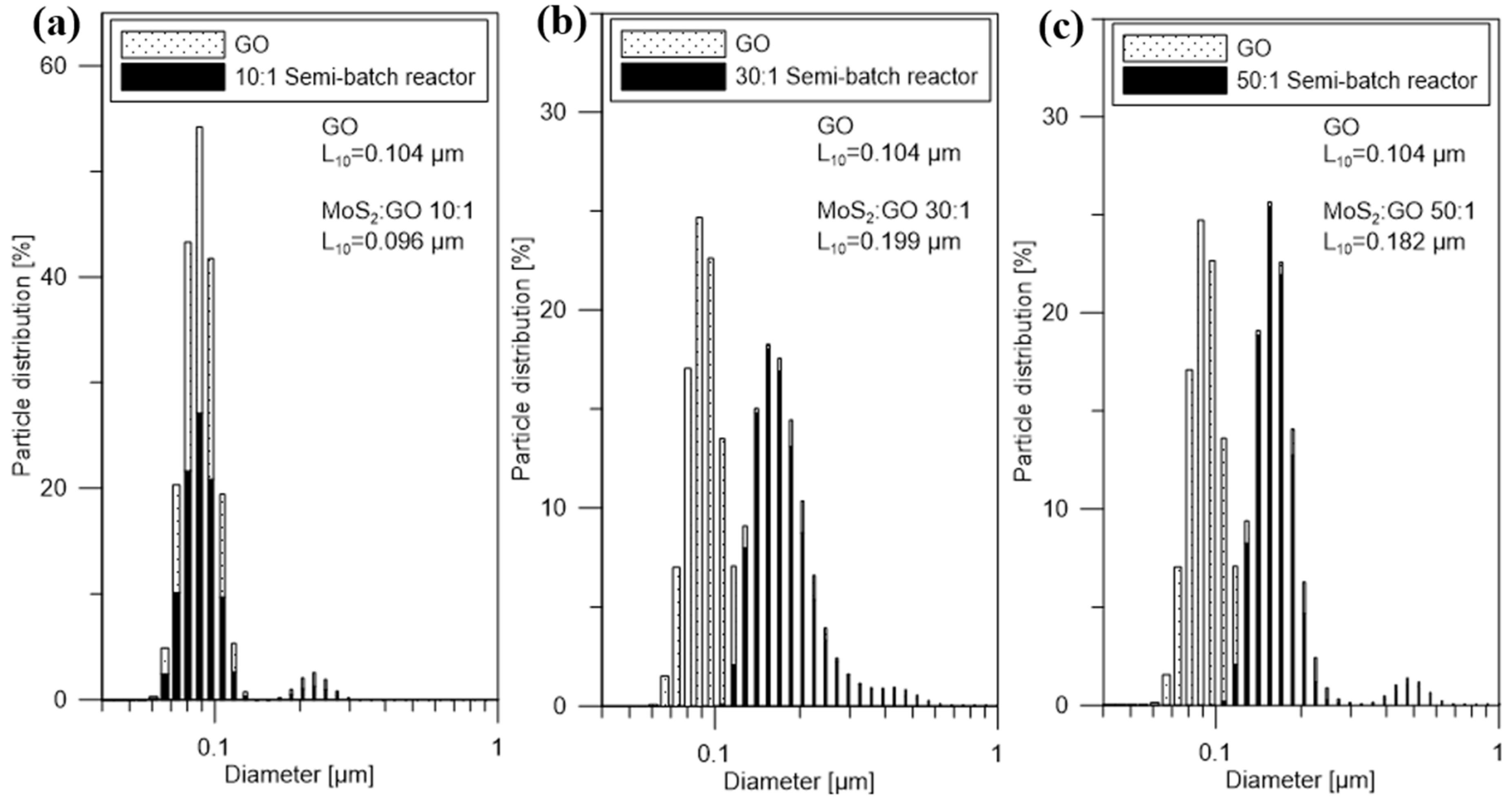
Figure 3 shows the particle size distributions of GO (just before the reaction) and MoS2/GO (direct products of the reaction in a semi-batch reactor) with different weight ratios. The characteristic particle sizes L10 of GO and MoS2/GO (10:1; 30:1; 50:1) were 0.104, 0.096, 0.199, 0.182 µm, respectively. The addition of carbon nanomaterials to the reaction environment allows primary heterogeneous nucleation to occur. MoS2 particles precipitated and continued to grow on graphene flakes, obtaining hybrid nanostructures. In samples 30:1 and 50:1 PSDs show that the characteristic particle size increased due to the coverage of GO flake by the synthesized MoS2 particles. In the case of the 10:1 sample, there was practically no change in the characteristic size. For this sample, the largest amount of GO was used, meaning it had the biggest amount of nucleation centers. The lack of change in this sample may indicate that the synthesized MoS2 particles were so small and evenly distributed on the GO surface that their formation did not affect the characteristic particle size. Compared to the precipitation of the pure MoS2 in the semi-batch reactor (as described in [42]) with the same process parameters (25 °C, initial Mo concentration of 0.2 mol/dm3), obtained hybrid nanostructures are more stable and have a lower tendency to agglomerate. PSDs of the hybrid nanostructures do not show the presence of agglomerates, and in the case of pure MoS2 PSD shows a distinct peak of agglomerates with the characteristic particle size equal to 1.4 µm [42].
Figure 4 shows the particle size distributions of GO (just before the reaction) and MoS2/GO (direct products of the reaction in the impinging jet reactor) with different weight ratios. The same as in the case of a semi-batch reactor, PSDs show that the characteristic particle size L10 increased due to the covering of GO flakes by MoS2 particles. The characteristic particle sizes L10 of MoS2/GO (10:1; 30:1; 50:1) were 0.096, 0.150, 0.073 µm, respectively. The use of the impinging jet reactor in the MoS2/GO synthesis allowed to obtain smaller particle sizes compared to the materials from the semi-batch reactor, due to the better mixing conditions. Similarly, as in the semi-batch procedure, obtained hybrid nanostructures are more stable and have a lower tendency to agglomerate.
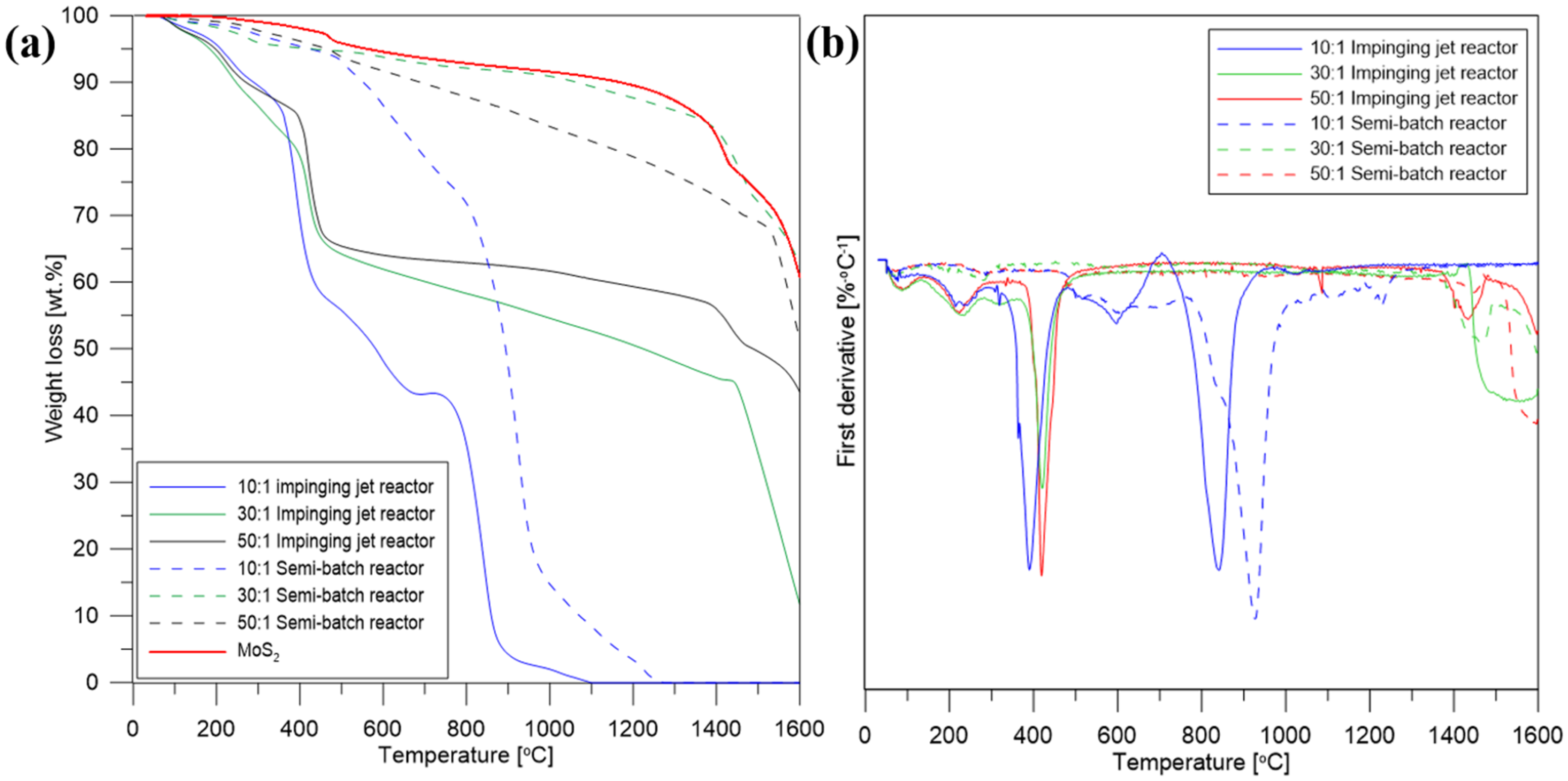
Thermogravimetric analysis of the purified and annealed materials is shown in Figure 5a and the derivative thermogravimetric analysis (DTG) in Figure 5b. A small initial weight loss at 100 °C for all samples corresponds to the evaporation of adsorbed water. Further weight loss around 200 °C for hybrid structures obtained in the impinging jet reactor is attributed to the removal of oxygen-containing functional groups from graphene oxide. For these samples another distinct weight decrease is visible around 400 °C, due to the oxidation of MoS2 to MoO3, resulting probably from the oxygen released during the degradation of GO. However, the materials synthesized in the semi-batch reactor do not show weight loss at this temperature range, hence the amount of oxygen from the GO structure wasn’t sufficient for the oxidation of MoS2 to MoO3 [55,56]. Further gradual weight loss of the rest of the samples corresponds to the removal of stable oxygen functional groups. Due to worse mixing conditions in the semi-batch reactor, it is likely that MoS2 particles were not only deposited on the carbon surface, but some were formed as a result of homogeneous nucleation. Therefore, some of the carbon material was not completely covered with MoS2 and due to its hydrophilic properties, some of GO was removed during purification, hence its lower content in the samples compared to the materials from the impinging jet reactor. TG analysis of the synthesized samples confirmed that the synthesis carried out in the impinging jet reactor allows to obtain stable hybrid nanostructures based on MoS2 and carbon nanomaterials.
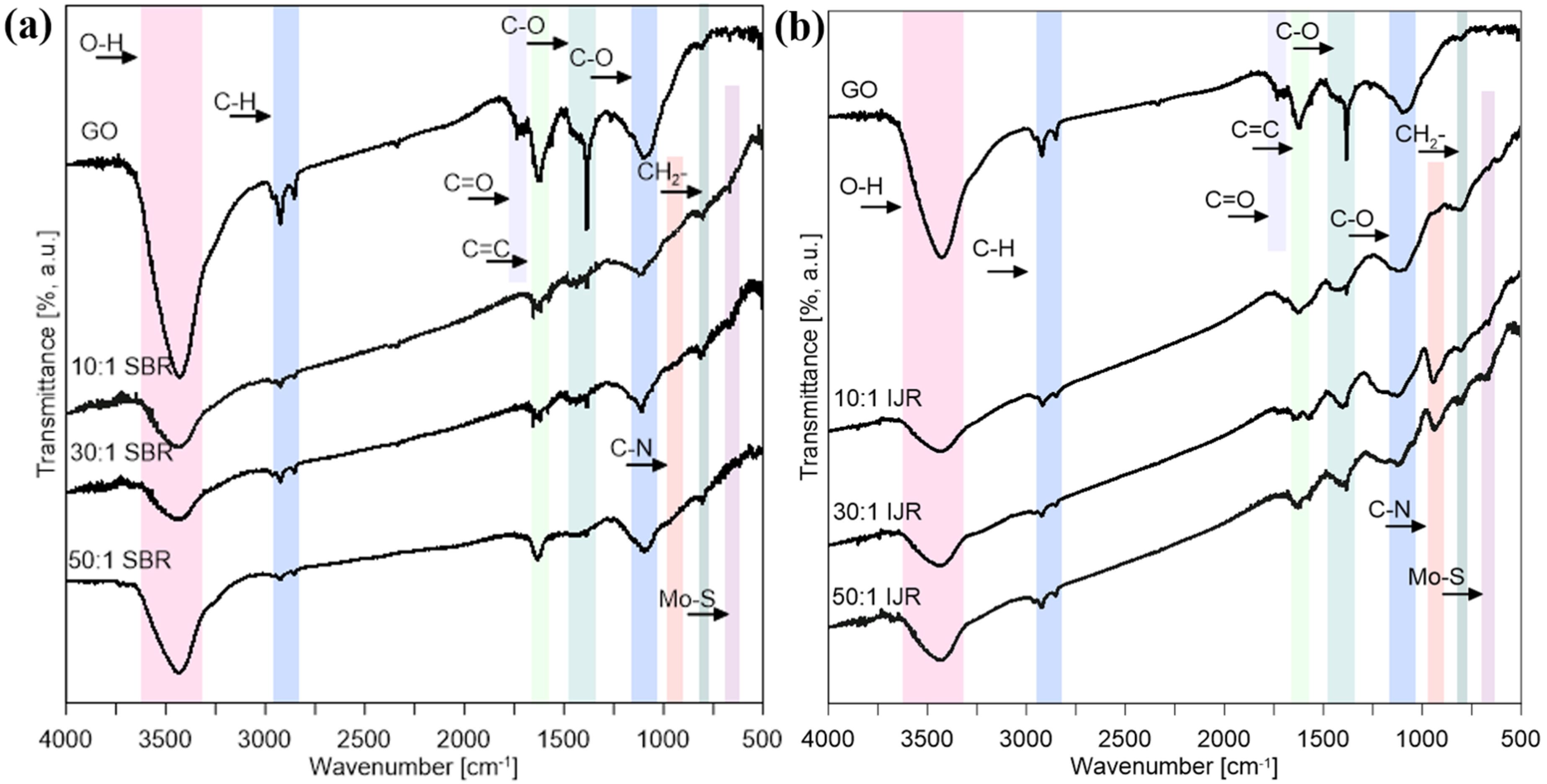
FT-IR spectra of GO, the structures synthesized in the semi-batch reactor and in the impinging jet reactor are shown in Figure 6. GO has shown characteristic peaks associated with O–H stretching at 3200–3600 cm−1, C–H stretching at 2850–2960 cm−1, carbonyl C=O stretching at 1710–1740 cm−1, C=C stretching about 1625 cm−1, C–O stretching vibration of alkoxy group at 1300–1420 cm−1, C–O stretching vibration of carboxyl groups at 1050–1150 cm−1, and CH2− at 760 cm−1 [57]. The decrease in the peak intensity of the oxygen-rich functional groups present in the synthesized nanostructures suggests a reduction in GO. In the case of the hybrid nanostructures, a peak associated with C–N stretching at 900–1000 cm−1 can be observed, suggesting that GO was additionally functionalized by HMA during the preparation of GO + HMA + CA suspension in the ultrasonic bath. For the samples obtained in the impinging jet reactor the signal of C–N stretching is stronger (Figure 6b). It might suggest that due to the high intensity of mixing in the area of collision of streams an additional functionalization is also taking place in the reactor. This functionalization can positively affect the electrochemical and photocatalytic properties of the obtained materials, due to the possibility of creating a p-n junction between the N–GO and MoS2 (which is a p-type semiconductor). Furthermore, a weak peak at 600 cm−1 is assigned to the Mo–S stretching vibration presented in MoS2-based materials [58].
XRD analysis (Figure 7) confirmed that synthesized MoS2 is crystalline with a hexagonal crystal structure 2H–MoS2. The average crystallite size is 9 nm in c-direction and 12 nm in a-direction. In the case of MoS2/GO from the semi-batch reactor the average size of MoS2 crystallites is 3.1 nm in c-direction and 7.4 nm in a-direction, and from impinging jet reactor it is ~1.6 nm in c-direction. The addition of GO to the synthesis of MoS2 allowed to obtain smaller crystallites. This is due to the fact that graphene oxide has many functional groups that can serve as nucleation sites for MoS2 particles. In the impinging jet reactor the obtained particles are smaller, which can be attributed to the better mixing conditions. Due to the lower annealing temperature of MoS2/GO, the hybrid nanostructures show lower crystallinity.
SEM images of the synthesized MoS2 are shown in Figure 8. As can be seen, synthesized molybdenum disulfide has a crystal structure with a layered surface and in the form of flakes. SEM images showed that MoS2 particles tend to agglomerate obtaining micrometer size.
Figure 9 shows SEM images of the obtained hybrid nanostructures in the semi-batch reactor. SEM images have confirmed the XRD results that MoS2 nanoparticles on GO are not fully crystalline. Nanoparticles of MoS2 are attached to the carbon surfaces, forming shapes close to GO flakes. With increasing MoS2 content, the hybrid structures resemble pure molybdenum disulfide. Furthermore, the hybrid nanostructures exhibit a lower tendency to agglomerate, comparing to pure MoS2 particles.
Figure 10 shows SEM images of the obtained hybrid nanostructures in the impinging jet reactor. As with the particles from the semi-batch reactor, the MoS2 nanoparticles are not fully crystalline. MoS2 nanoparticles can be observed on the GO flakes’ surface (Figure 10a). This structure is different than for the samples obtained in the semi-batch reactor, confirming the XRD results that the particles are smaller. In the pictures it can be seen that MoS2 particles attach to GO surface, changing their morphology. In both cases (semi-batch and impinging jet reactor) MoS2 seems to be agglomerated (except in Figure 10a, where small MoS2 nanoparticles are evenly distributed on the GO surface) and no big differences between the two synthesis methods can be observed. During the synthesis of MoS2/GO hybrid structures two processes can occur: heteronucleation, where MoS2 nanoparticles will form on GO surface and homonucleation, where MoS2 will form in the solution. SEM and PSD results suggest that most of the MoS2 particles tend to form on GO flakes, meaning that the formation of MoS2 nanoparticles is mainly through heteronucleation.
Figure 11a shows the linear sweep voltammetry of the obtained samples. The polarization curves of synthesized and commercial MoS2 have an onset potential (potential with current density ~0 mA/cm2) of −0.63 V, −0.54 V, respectively, and show a sharp decrease in the current density as the potential decreases. In the case of the hybrid nanostructures obtained in the semi-batch reactor (10:1; 30:1; 50:1), the onset potential was −0.40 V, −0.48 V, −0.43 V, respectively, and for the samples from the impinging jet reactor (10:1; 30:1; 50:1) it was −0.39 V, −0.39 V, −0.36 V, respectively. The addition of GO increases the onset potential, possibly due to the formation of smaller MoS2 nanoparticles exhibiting more active sites than pure MoS2. Another reason for this effect is because carbon flakes serve as conducting support, causing enhanced electrical conductivity and improving the interfacial charge transfer as well as suppression of charge recombination. The 50:1 ratio (both from the impinging jet reactor and semi-batch reactor) exhibits the best catalytic performance. Probably, this ratio allows for uniform precipitation of MoS2 on the carbonaceous surface and obtaining nano-sized particles (PSD results). The hybrid nanostructures synthesized in the impinging jet reactor have shown better electrochemical properties, due to the better mixing conditions, providing better dispersion of MoS2 particles on the GO surface. Another explanation for this result might be connected to additional functionalization of GO with nitrogen groups during the synthesis of the hybrid structures, which can possibly create a p-n junction between the N-GO and MoS2, enhancing the catalytic properties. The LSV curves and onset potential are similar, indicating that the use of impinging jet reactor allows to obtain products with repeatable properties. Figure 11b shows the fifth measurement of LSV. As can be seen, obtained polarization curves for MoS2 particles change during the measurements, while for the hybrid nanostructures they are repeatable, hence the addition of GO improves electrochemical stability of MoS2 particles.

4. Conclusions

The hybrid nanostructures based on molybdenum disulfide and graphene oxide can be successfully obtained in the semi-batch reactor and the impinging jet reactor. Due to the better mixing conditions, materials obtained in the impinging jet reactor have shown better dispersion of MoS2 particles on the carbon surface, smaller particle size, less tendency to agglomerate, and higher carbon material contents. During preparation, GO was additionally functionalized by HMA, confirmed by FT-IR measurements, which can be observed especially in the samples from the impinging jet reactor, probably due to the high intensity of mixing in the area of collision of streams. This functionalization can positively affect the electrochemical and photocatalytic properties of the materials obtained, due to the possibility of creating a p-n junction between carbon and MoS2 particles. The hybrid nanostructures obtained in the impinging jet reactor have shown better electrochemical properties and higher onset potentials. The results indicated that addition of carbon nanomaterials during the synthesis improves the activity and stability of the MoS2.

Author Contributions

Conceptualization, Z.B., M.M.-P. and Ł.M.; methodology, Z.B., M.M.-P., S.G. and Ł.M.; validation, Z.B., M.M.-P., S.G. and Ł.M.; formal analysis, Z.B., M.M.-P., S.G. and Ł.M.; investigation, Z.B., M.M.-P., S.G. and Ł.M.; resources, Z.B., M.M.-P. and Ł.M.; writing—original draft preparation, Z.B. and M.M.-P.; writing—review and editing, Z.B., M.M.-P. and Ł.M.; visualization, Z.B.; supervision, M.M.-P. and Ł.M.; project administration, Ł.M., M.M.-P.; funding acquisition, Ł.M. and M.M.-P. All authors have read and agreed to the published version of the manuscript.

Funding

This research was funded by the National Science Centre [Decision No. DEC-2017/27/B/ST8/01382]. Graphene oxide was obtained during realization of the project [No.PL-TWIII/4/2016] by the National Centre for Research and Development.

Conflicts of Interest

The authors declare no conflict of interest.

References

  1. Li, X.; Zhu, H. Two-dimensional MoS2: Properties, preparation, and applications. J. Mater. 2015. [Google Scholar] [CrossRef] [Green Version]
  2. He, Z.; Que, W. Molybdenum disulfide nanomaterials: Structures, properties, synthesis and recent progress on hydrogen evolution reaction. Appl. Mater. Today 2016. [Google Scholar] [CrossRef]
  3. Wang, H.D.; Xu, B.-S.; Liu, J.-J.; Zhuang, D.-M. Characterization and anti-friction on the solid lubrication MoS2 film prepared by chemical reaction technique. Sci. Technol. Adv. Mater. 2005. [Google Scholar] [CrossRef] [Green Version]
  4. Boone, W.P.; Ekerdt, J.G. Hydrodesulfurization studies with a single-layer molybdenum disulfide catalyst. J. Catal. 2000. [Google Scholar] [CrossRef]
  5. Wang, T.; Chen, S.; Pang, H.; Xue, H.; Yu, Y. MoS2-based nanocomposites for electrochemical energy storage. Adv. Sci. 2017. [Google Scholar] [CrossRef]
  6. Shi, J. Single-atom co-doped MoS2 monolayers for highly active biomass hydrodeoxygenation. Chemical 2017. [Google Scholar] [CrossRef] [Green Version]
  7. Zhang, X.; Teng, S.Y.; Loy, A.C.M.; How, B.S.; Leong, W.D.; Tao, X. Transition metal dichalcogenides for the application of pollution reduction: A review. Nanomaterials 2020, 10, 1012. [Google Scholar] [CrossRef]
  8. De León, J.N.D.; Kumar, C.R.; Antúnez-García, J.; Fuentes-Moyado, S. Recent insights in transition metal sulfide hydrodesulfurization catalysts for the production of ultra low sulfur diesel: A short review. Catalysts 2019, 9, 87. [Google Scholar] [CrossRef] [Green Version]
  9. Li, Y.; Wang, H.; Xie, L.; Liang, Y.; Hong, G.; Dai, H. MoS2 nanoparticles grown on graphene: An advanced catalyst for the hydrogen evolution reaction. J. Am. Chem. Soc. 2011. [Google Scholar] [CrossRef] [Green Version]
  10. Zhou, J.; Xiao, H.; Zhou, B.; Huang, F.; Zhou, S.; Xiao, W.; Wang, D. Hierarchical MoS2 -rGO nanosheets with high MoS2 loading with enhanced electro-catalytic performance. Appl. Surf. Sci. 2015. [Google Scholar] [CrossRef]
  11. Xiang, Q.; Yu, J.; Jaroniec, M. Synergetic effect of MoS2 and graphene as cocatalysts for enhanced photocatalytic H 2 production activity of TiO2 nanoparticles. J. Am. Chem. Soc. 2012. [Google Scholar] [CrossRef] [PubMed]
  12. Ding, Y.; Zhou, Y.; Nie, W.; Chen, P. MoS2 -GO nanocomposites synthesized via a hydrothermal hydrogel method for solar light photocatalytic degradation of methylene blue. Appl. Surf. Sci. 2015. [Google Scholar] [CrossRef]
  13. Zhang, F.X.; Li, C.S.; Zhang, Y.; Tang, H. Tribological property of RGO/MoS2 and CNTs/MoS2 as lubricated oil additives. Rengong Jingti Xuebao/J. Synth. Cryst. 2015, 44, 801–807. [Google Scholar]
  14. Hou, K.; Wang, J.; Yang, Z.; Ma, L.; Wang, Z.; Yang, S. One-pot synthesis of reduced graphene oxide/molybdenum disulfide heterostructures with intrinsic incommensurateness for enhanced lubricating properties. Carbon 2017. [Google Scholar] [CrossRef]
  15. Bae, D.; Seger, B.; Vesborg, P.C.K.; Hansen, O.; Chorkendorff, I. Strategies for stable water splitting: Via protected photoelectrodes. Chem. Soc. Rev. 2017. [Google Scholar] [CrossRef] [Green Version]
  16. Owusu, P.A.; Asumadu-Sarkodie, S. A review of renewable energy sources, sustainability issues and climate change mitigation. Cogent Eng. 2016. [Google Scholar] [CrossRef]
  17. Liu, N.; Kim, J.; Oh, J.; Nguyen, T.Q.; Sahu, B.B.; Han, J.G.; Kim, S. Growth of multiorientated polycrystalline MoS2 using plasma-enhanced chemical vapor deposition for efficient hydrogen evolution reactions. Nanomaterials 2020, 10, 1465. [Google Scholar] [CrossRef]
  18. Yao, Y.; Ao, K.; Lv, P.; Wei, Q. MoS2 coexisting in 1T and 2H phases synthesized by common hydrothermal method for hydrogen evolution reaction. Nanomaterials 2019, 9, 844. [Google Scholar] [CrossRef] [Green Version]
  19. Eftekhari, A. Electrocatalysts for hydrogen evolution reaction. Int. J. Hydrogen Energy 2017. [Google Scholar] [CrossRef]
  20. She, Z.W.; Kibsgaard, J.; Dickens, C.F.; Chorkendorff, I.; Nørskov, J.K.; Jaramillo, T.F. Combining theory and experiment in electrocatalysis: Insights into materials design. Science 2017. [Google Scholar] [CrossRef] [Green Version]
  21. Han, B.; Hu, Y.H. MoS2 as a co-catalyst for photocatalytic hydrogen production from water. Energy Sci. Eng. 2016. [Google Scholar] [CrossRef] [Green Version]
  22. Christoforidis, K.C.; Fornasiero, P. Photocatalytic hydrogen production: A rift into the future energy supply. ChemCatChem 2017. [Google Scholar] [CrossRef] [Green Version]
  23. Barthelemy, H.; Weber, M.; Barbier, F. Hydrogen storage: Recent improvements and industrial perspectives. Int. J. Hydrogen Energy 2017. [Google Scholar] [CrossRef]
  24. Benck, J.D.; Hellstern, T.R.; Kibsgaard, J.; Chakthranont, P.; Jaramillo, T.F. Catalyzing the hydrogen evolution reaction (HER) with molybdenum sulfide nanomaterials. ACS Catal. 2014. [Google Scholar] [CrossRef]
  25. Vesborg, P.C.K.; Seger, B.; Chorkendorff, I. Recent development in hydrogen evolution reaction catalysts and their practical implementation. J. Phys. Chem. Lett. 2015. [Google Scholar] [CrossRef] [PubMed]
  26. Yang, L.; Liu, P.; Li, J.; Xiang, B. Two-dimensional material molybdenum disulfides as electrocatalysts for hydrogen evolution. Catalysts 2017, 7, 285. [Google Scholar] [CrossRef] [Green Version]
  27. Yang, L.; Zhang, J.; Feng, C.; Xu, G.; Xie, C.; Yuan, X.; Xiang, B. MoS2 nanosheet/MoS2 flake homostructures for efficient electrocatalytic hydrogen evolution. Mater. Res. Express 2019. [Google Scholar] [CrossRef]
  28. Benson, E.E.; Zhang, H.; Schuman, A.; Nanayakkara, S.U.; Bronstein, N.D.; Ferrere, S.; Blackburn, J.L.; Miller, E.M. Balancing the hydrogen evolution reaction, surface energetics, and stability of metallic MoS2 nanosheets via covalent functionalization. J. Am. Chem. Soc. 2018. [Google Scholar] [CrossRef]
  29. Benck, J.D.; Chen, Z.; Kuritzky, L.Y.; Forman, A.J.; Jaramillo, T.F. Amorphous molybdenum sulfide catalysts for electrochemical hydrogen production: Insights into the origin of their catalytic activity. ACS Catal. 2012. [Google Scholar] [CrossRef]
  30. Zhao, W.; Liu, X.; Yang, X.; Liu, C.; Qian, X.; Sun, T.; Chang, W.; Zhang, J.; Chen, Z. Synthesis of novel 1t/2h- MoS2 from moo3 nanowires with enhanced photocatalytic performance. Nanomaterials 2020, 10, 1124. [Google Scholar] [CrossRef]
  31. Chang, K.; Pang, H.; Hai, X.; Zhao, G.; Zhang, H.; Shi, L.; Ichihara, F.; Ye, J. Ultra-small freestanding amorphous molybdenum sulfide colloidal nanodots for highly efficient photocatalytic hydrogen evolution reaction. Appl. Catal. B Environ. 2018. [Google Scholar] [CrossRef]
  32. Zhao, Q.; Guo, Y.; Zhou, Y.; Yan, X.; Xu, X. Solution-processable exfoliation and photoelectric properties of two-dimensional layered MoS2 photoelectrodes. J. Colloid Interface Sci. 2017. [Google Scholar] [CrossRef]
  33. Si, K.; Ma, J.; Guo, Y.; Zhou, Y.; Lu, C.; Xu, X.; Xu, X. Improving photoelectric performance of MoS2 photoelectrodes by annealing. Ceram. Int. 2018. [Google Scholar] [CrossRef]
  34. Meng, F.; Li, J.; Cushing, S.K.; Zhi, M.; Wu, N. Solar hydrogen generation by nanoscale p-n junction of p-type molybdenum disulfide/n-type nitrogen-doped reduced graphene oxide. J. Am. Chem. Soc. 2013. [Google Scholar] [CrossRef]
  35. Zhou, H.; Liu, Y.; Zhang, L.; Li, H.; Liu, H.; Li, W. Transition metal-doped amorphous molybdenum sulfide/graphene ternary cocatalysts for excellent photocatalytic hydrogen evolution: Synergistic effect of transition metal and grapheme. J. Colloid Interface Sci. 2019. [Google Scholar] [CrossRef]
  36. Salarizadeh, P.; Askari, M.B.; Seifi, M.; Rozati, S.M. MoS2 coating on different carbonaceous materials: Comparison of electrochemical properties and hydrogen evolution reaction performance. J. Electroanal. Chem. 2019. [Google Scholar] [CrossRef]
  37. Shi, Y.; Zhou, W.; Lu, A.-Y.; Fang, W.; Lee, Y.-H.; Hsu, A.L.; Kim, S.M.; Kim, K.K.; Yang, H.Y.; Li, L.-J.; et al. Van der waals epitaxy of MoS2 layers using graphene as growth templates. Nano Lett. 2012. [Google Scholar] [CrossRef]
  38. Li, J.; Liu, X.; Pan, L.; Qin, W.; Chen, T.; Sun, Z. MoS2-reduced graphene oxide composites synthesized via a microwave-assisted method for visible-light photocatalytic degradation of methylene blue. RSC Adv. 2014. [Google Scholar] [CrossRef]
  39. Song, H.; Tang, A.; Xu, G.; Liu, L.; Yin, M.; Pan, Y. One-step convenient hydrothermal synthesis of MoS2/RGO as a high-performance anode for sodium-ion batteries. Int. J. Electrochem. Sci. 2018. [Google Scholar] [CrossRef]
  40. Murugan, M.; Kumar, R.M.; Alsalme, A.; Alghamdi, A.; Jayavel, R. Synthesis and property studies of molybdenum disulfide modified reduced graphene oxide (MoS2-rGO) Nanocomposites for Supercapacitor Applications. J. Nanosci. Nanotechnol. 2017. [Google Scholar] [CrossRef]
  41. Kumar, S.; Sahoo, P.K.; Satpati, A.K. Electrochemical and SECM Investigation of MoS2/GO and MoS2/rGO Nanocomposite Materials for HER Electrocatalysis. ACS Omega 2017. [Google Scholar] [CrossRef] [PubMed]
  42. Wojtalik, M.; Bojarska, Z.; Makowski, Ł. Experimental studies on the chemical wet synthesis for obtaining high-quality MoS2 nanoparticles using impinging jet reactor. J. Solid State Chem. 2020. [Google Scholar] [CrossRef]
  43. Wojtalik, M.; Przybyt, P.; Zubanska, K.; Zuchowska, M.; Bojarska, Z.; Arasimowicz-Andres, M.; Rozen, A.; Makowski, L. Production of synthetic particles of MoS2 using wet chemical synthesis. Przem. Chem. 2019. [Google Scholar] [CrossRef]
  44. Wojtalik, M.; Orciuch, W.; Makowski, Ł. Nucleation and growth kinetics of MoS2 nanoparticles obtained by chemical wet synthesis in a jet reactor. Chem. Eng. Sci. 2020. [Google Scholar] [CrossRef]
  45. Wojtas, K.; Makowski, Ł.; Orciuch, W. Barium sulfate precipitation in jet reactors: Large eddy simulations, kinetics study and design considerations. Chem. Eng. Res. Des. 2020. [Google Scholar] [CrossRef]
  46. Makowski, Ł.; Bałdyga, J. Large Eddy Simulation of mixing effects on the course of parallel chemical reactions and comparison with k-e{open} modeling. Chem. Eng. Process. Process Intensif. 2011. [Google Scholar] [CrossRef]
  47. Wojtas, K.; Orciuch, W.; Wysocki, Ł.; Makowski, Ł. Modeling and experimental validation of subgrid scale scalar variance at high Schmidt numbers. Chem. Eng. Res. Des. 2017. [Google Scholar] [CrossRef]
  48. Makowski, Ł.; Orciuch, W.; Bałdyga, J. Large eddy simulations of mixing effects on the course of precipitation process. Chem. Eng. Sci. 2012. [Google Scholar] [CrossRef]
  49. Gavi, E.; Rivautella, L.; Marchisio, D.L.; Vanni, M.; Barresi, A.A.; Baldi, G. CFD modelling of nano-particle precipitation in confined impinging jet reactors. Chem. Eng. Res. Des. 2007. [Google Scholar] [CrossRef]
  50. Stobinski, L.; Lesiak, B.; Malolepszy, A.; Mazurkiewicz, M.; Mierzwa, B.; Zemek, J.; Jiricek, P.; Bieloshapka, I. Graphene oxide and reduced graphene oxide studied by the XRD, TEM and electron spectroscopy methods. J. Electron Spectrosc. Relat. Phenom. 2014. [Google Scholar] [CrossRef]
  51. Mazurkiewicz-Pawlicka, M.; Nowak, M.; Malolepszy, A.; Witowski, A.; Wasik, D.; Hu, Y.; Stobinski, L. Graphene oxide with controlled content of oxygen groups as a filler for polymer composites used for infrared radiation shielding. Nanomaterials 2020, 10, 32. [Google Scholar] [CrossRef] [PubMed] [Green Version]
  52. Wu, L.; Longo, A.; Dzade, N.; Sharma, A.; Hendrix, M.M.R.M.; Bol, A.A.; de Leeuw, N.H.; Hensen, E.J.M.; Hofmann, J.P. The origin of high activity of amorphous MoS2 in the hydrogen evolution reaction. ChemSusChem 2019. [Google Scholar] [CrossRef] [Green Version]
  53. Zhang, X.; Zhang, Y.; Yu, B.-B.; Yin, X.-L.; Jiang, W.-J.; Jiang, Y.; Hu, J.-S.; Wan, L.-J. Physical vapor deposition of amorphous MoS2 nanosheet arrays on carbon cloth for highly reproducible large-area electrocatalysts for the hydrogen evolution reaction. J. Mater. Chem. A 2015. [Google Scholar] [CrossRef]
  54. Greenwood, N.N.; Earnshaw, A. Chemistry of Elements. Cryst. Res. Technol. 1968. [Google Scholar] [CrossRef]
  55. Zou, L.; Qu, R.; Gao, H.; Guan, X.; Qi, X.; Liu, C.; Zhang, Z.; Lei, X. MoS2/RGO hybrids prepared by a hydrothermal route as a highly efficient catalytic for sonocatalytic degradation of methylene blue. Results Phys. 2019. [Google Scholar] [CrossRef]
  56. Akbarzadeh, E.; Setayesh, S.R.; Gholami, M.R. Investigating the role of MoS2/reduced graphene oxide as cocatalyst on Cu2O activity in catalytic and photocatalytic reactions. New J. Chem. 2017. [Google Scholar] [CrossRef]
  57. Bojarska, Z.; Mazurkiewicz-Pawlicka, M.; Makowski, Ł. Graphene oxide-based nanomaterials as catalysts for oxygen reduction reaction. Chem. Process. Eng. Inz. Chem. Proces. 2019. [Google Scholar] [CrossRef]
  58. Vinoth, R.; Patil, I.M.; Pandikumar, A.; Kakade, B.A.; Huang, N.M.; Dionysios, D.D.; Neppolian, B. Synergistically enhanced electrocatalytic performance of an n-doped graphene quantum dot-decorated 3d MoS2-graphene nanohybrid for oxygen reduction reaction. ACS Omega 2016. [Google Scholar] [CrossRef]
Figure 1. Synthesis of Molybdenum disulfide (MoS2)/ graphene oxide (GO) in the semi-batch reactor.
Nanomaterials 10 01865 g001
Figure 2. Synthesis of MoS2/GO in the impinging jet reactor.
Nanomaterials 10 01865 g002
Figure 3. Particle size distribution profiles by number of particles of direct products of the reaction in the semi-batch system for MoS2/GO ratio (a) 10:1 (b) 30:1 (c) 50:1, and GO just before the reaction.
Nanomaterials 10 01865 g003
Figure 4. Particle size distribution profiles by number of particles of direct products of the reaction in the impinging jet reactor for MoS2/GO ratio (a) 10:1 (b) 30:1 (c) 50:1 and GO just before the reaction.
Nanomaterials 10 01865 g004
Figure 5. (a) Thermogravimetric analysis and (b) derivative thermogravimetric of the hybrid nanostructures and MoS2.
Nanomaterials 10 01865 g005
Figure 6. Fourier-transform infrared (FT-IR) spectra of GO and MoS2/GO synthesized in (a) the semi-batch reactor (b) the impinging jet reactor.
Nanomaterials 10 01865 g006
Figure 7. X-ray diffraction (XRD) patterns of MoS2, MoS2/GO synthesized in the semi-batch reactor and in the impinging jet reactor.
Nanomaterials 10 01865 g007
Figure 8. Images of synthesized MoS2 particles in (a,c) the bright-field scanning transmission electron microscopy (BF-STEM) and (b,d) in secondary electrons (SE) modes.
Nanomaterials 10 01865 g008
Figure 9. Images of MoS2/GO form in the semi-batch reactor in weight ratios of (a) 10:1, (b) 30:1, (c) 50:1 in SE and BF-STEM modes.
Nanomaterials 10 01865 g009
Figure 10. Images of MoS2/GO form in the impinging jet reactor in weight ratios of (a) 10:1, (b) 30:1, (c) 50:1 in SE and BF-STEM modes.
Nanomaterials 10 01865 g010
Figure 11. Linear sweep voltammograms of MoS2 and MoS2/GO performed using three electrodes system (Platinum wire as counter electrode and Ag/AgCl as reference electrode) (a) the first measurement, (b) the fifth measurement.
Nanomaterials 10 01865 g011
Table 1. The weight of reagents used. HMA: ammonium heptamolybdate tetrahydrate; AS: ammonium sulfide; CA: Citric acid.
MoS2/GO Ratio10:130:150:1
Volume of reagents’ solution [mL]20
20 wt.% AS mass [mL]2.734
HMA mass [g]0.706
CA mass [g]1.537
0.34 wt.% GO mass [g]12.5564.1862.512