Abstract
As the two types of major impurities in FCC slurry oil (SLO), olefins and sulfur seriously deteriorate the preparation and quality of mesophase pitch or needle coke. The development of a hydrotreatment for SLO to remove olefins and sulfur selectively becomes imperative. This work presents the potentiality of dispersed Mo2C and MoS2 nanoparticles as selective hydrotreating catalysts of SLO. Mo2C was synthesized by the carbonization of citric acid, ammonium molybdate and KCl mixtures while MoS2 was prepared from the decomposition of precursors. These catalysts were characterized by XRD, HRTEM, XPS, BJH, BET, and applied to the hydrotreating of an SLO surrogate with defined components and real SLO. The conversion of olefins, dibenzothiophene and anthracene in the surrogate was detected by GC-MS. Elemental analysis, bromine number, diene value, 1H-NMR and spot test were used to characterize the changes of the real SLO. The results show that hydrotreating the SLO surrogate with a very small amount of Mo-based nanoparticles could selectively remove olefins and sulfur without the overhydrogenation of polyaromatics. Mo2C exhibited much better activity than MoS2, with 95% of olefins and dibenzothiophene in the surrogate removed while only 15% anthracene was hydrogenated. The stability of the real SLO was significantly improved. Its structural parameters changed subtly, proving the aromatic macromolecules had been preserved.
1. Introduction
Slurry oil (SLO) is an important byproduct in the fluidized catalytic cracking (FCC) process. Due to the ever-increasing supply of heavy oil with the short fall of conventional crudes and persistent high demand for light fuels, the production of SLO rises and its quality inevitably becomes inferior [1]. Since SLO is enriched with 3–5 rings of polycyclic aromatic hydrocarbons (PAHs) with short side chains, it is widely known as an excellent potential raw material to produce mesophase pitch and needle coke, which could heighten its utilization value remarkably [2,3,4]. Nevertheless, the impurities in SLO could seriously deteriorate the quality of the prepared carbonaceous material, among which sulfur and olefins are the most critical factors [5,6,7]. The sulfur in needle coke with a content higher than 0.5 wt% can cause irreversible volume expansion (i.e., puffing) during graphitization heat treatment, reducing the strength and electrical conductivity of the electrodes [8,9]. In the meantime, the olefins are important chemically active intermediates and products in the FCC process. Our group has identified the olefins widely distributed in SLO, and found that they could worsen the thermal stability of SLO, induce a premature coke of SLO thermal processing, and hamper the orderly development of mesophase pitch [7,10]. Therefore, as the most practical and efficient way to remove olefins and sulfur, the selective hydrotreating of SLO is imperative for chemical structure modification of SLO and deserves great attention for high-value SLO utilization.
The hydrotreating of various straight-run or cracking distillates (i.e., gasoline, diesel, and vacuum gas oil) and residues is extensively achieved using the transition metal sulfides supported on porous materials as catalysts [11,12,13,14,15]. Despite the pioneering research of SLO hydrotreating over alumina-supported Co-Mo or Ni-Mo catalysts that has been reported, their main concern was to remove the sulfur in SLO and thus control the sulfur levels in needle coke [16,17,18,19]. In contrast, detailed information on olefins removal of SLO through selective hydrotreating is extremely limited. As stated by Abrahamson et al. [18], the aromatic/aliphatic hydrocarbon ratio is an important structural parameter of SLO for coke morphology modification. Hence, an efficient catalyst for the selective hydrotreating of SLO should possess a high activity for sulfur and olefins removal, but a low activity for the hydrogenation of PAHs.
To date, molybdenum-based nanoparticles (e.g., MoS2 and Mo2C) have attracted great attention for hydrogenation reactions because of their high abundance and low cost [20,21,22]. MoS2 is well known as the catalytic active sites for dispersed catalyst in the slurry-phase hydrocracking process of heavy oil [23,24]. It can be prepared in situ from water-soluble and oil-soluble catalytic precursors and thus dispersed in the oil system, which could avoid the block issue of the catalyst bed. Meanwhile, the relevant researchers suggested that MoS2 could simultaneously display catalytic activity for aromatics hydrogenation during hydrotreating, resulting in a reduced selectivity for sulfur and olefins removal [25]. The ability of dispersed MoS2 for the transformation of bicyclic aromatics was discussed by Deng et al. in detail [26]. The hydrotreatment of light cycle oil over a dispersed MoS2 catalyst, as conducted by Zhang et al. [25], found that about 81% of the bicyclic aromatics were hydrogenated to monocyclic aromatics while the monocyclic aromatics and polyaromatics were barely eliminated. Conversely, the exploration of Hu et al. indicated that phenanthrene could be converted to different hydrogenated intermediates on a dispersed MoS2 catalyst [27]. The hydrogenation of naphthalene, phenanthrene, and pyrene were observed over MoS2 by Dutta et al. [28], and the conversion was higher than 50%. Clearly, the hydrogenation selectivity of MoS2 for olefins and sulfur compounds remains to be revealed in the case of the overhydrogenation of aromatics. Kaluža et al. [14] even found that the MoS2 catalysts exhibited higher selectivity to the hydrogenation of olefins (HYDO) while the CoMoS and NiMoS showed lower selectivity towards HYDO during the hydrogenation of 1-benzothiophene/1-methyl-1-cyclohexene. It further suggests MoS2 might be a better candidate for the deep hydrogenation of olefins. In addition to MoS2, molybdenum carbide (Mo2C) nanoparticles showed excellent catalytic performance for electrocatalytic hydrogen evolution, water-gas shift reaction, hydrodesulfurization, hydrodeoxygenation and hydrodenitrogenation because of the platinum (Pt)-like d-band electronic structure by inducing carbon into the metal lattice [29,30,31,32,33,34,35,36,37,38]. Compared with noble metal catalysts, Mo2C catalysts are of higher sulfur tolerance and better stability. As reported by Aegerter et al. [39], β-Mo2C possessed a higher thiophene HDS activity than MoS2, and had the potential to replace MoS2 in commercial HDS reactors. Sajkowski et al. [40] studied the hydrotreating of coal-derived gas oil and residuum over Mo2C/Al2O3, and the results showed that the catalytic rates over Mo2C could be as much as five times that of MoS2/A12O3. Qiu et al. [41] conducted the hydrodenitrogenation of quinoline over β-Mo2C. It was found that Mo2C exhibited remarkable selectivity for denitrogenation and low activity for aromatic ring destruction. According to the available literature, the Mo2C catalysts have never been utilized in the selective hydrotreating of SLO.
In this paper, Mo2C was synthesized ex situ by the carbonization of citric acid, ammonium molybdate and KCl mixtures while MoS2 was obtained in situ from the decomposition of water-soluble and oil-soluble precursors. These catalysts were characterized in detail by X-ray diffraction (XRD), high resolution transmission electron microscopy (HRTEM), X-ray photoelectron spectroscopy (XPS), Brunauer Emmett Teller (BET) and Barrett-Joyner-Halenda analysis (BJH), and then applied for the hydrotreating of the SLO surrogate with defined components and the real SLO. The conversion of different model compounds in the surrogate was detected by GC-MS. Elemental analysis, bromine number, diene value, 1H-NMR and spot test were used to characterize the changes of the real SLO. The potentiality of Mo2C and MoS2 nanoparticles as selective hydrotreating catalysts of SLO to remove olefins and sulfur was discussed.
2. Materials and Methods
2.1. Preparation of Catalysts
The purity and suppliers of the chemicals used in the present work are provided in Table S1 as supporting information. A total of 4.0 g ammonium molybdate tetrahydrate (AMT) and 1.2451 g citric acid monohydrate (CAM), 0.338 g potassium chloride and 0.8044 g ethylene glycol were mixed with 50 mL deionized water, and the pH value of the solution was kept at 1.5 by adding nitric acid. The wet gel was prepared by removing water with a rotary evaporator, and then vacuum dried at 110 °C for 4.0 h. The resultant powder was ground to 60–100 mesh and carbonized under nitrogen with a flow rate of 100 L/min at 800 °C with a heating rate of 5 °C/min. After the carbonization, the sample was passivated at 800 °C for 2 h using 1% O2-Ar mixture to obtain the final Mo2C catalyst.
The MoS2 catalysts were prepared by solvothermal method from oil-soluble precursor molybdenum dialkyl dithiocarbamate (Mo-DTC) and water-soluble precursor ammonium molybdate tetrahydrate (AMT), which were designated as O-MoS2 and W-MoS2, respectively. Mo-DTC was decomposed and self-sulfurized in 1-methylnaphthalene media under hydrogen at the optimized temperature of 380 °C for 45 min to obtain O-MoS2 catalyst. For preparation of W-MoS2, AMT was decomposed and sulfurized using sulfur as the sulfiding agent at the optimized temperature of 340 °C for 30 min. To prevent the oxidation as much as possible, MoS2 samples were soaked in ethanol before characterization.
2.2. Characterization of Catalysts
The crystal structure of the samples was characterized by using XRD system (X‘Pert Pro MPD) equipped with a Cu-Kα irradiation source in the 2θ range of 5–75° with a scanning speed of 5°·min−1. The morphologies of samples were measured by TEM (JEM-2100UHR, Japan Electronics Co., Ltd., Tokyo, Japan) at 5 kV accelerated voltage. XPS analysis was performed on a K-alpha 250Xi spectrometer (Thermo Fisher Scientific, Waltham, MA, USA) with an Ar ion source at 0.5–1.5 KeV. BET specific surface areas and BJH pore size distribution of catalysts were determined based on the nitrogen physisorption measurement using ASAP 2020M/Micromeritics instrument (Micromeritics Instrument Co., Norcross, GA, USA). During nitrogen physisorption measurement, the wet MoS2 samples with ethanol were degassed at 150 °C under vacuum for 10 h before analysis.
2.3. Hydrotreating of SLO Surrogate and SLO
Based on our previous work [7], the readily available conjugated olefins and monoolefin (styrene, trans-stilbene, and 1-octene) were used as the olefin model compounds due to their similar structures to the native olefins identified in slurry oil. Dibenzothiophene and anthracene were selected as model of the sulfur-containing and aromatic compound, respectively. The bulk solvent of simulated slurry oil was determined as 1-methylnaphthalene. The weight percentages of the five components in 1-methylnaphthalene are 3.33% styrene, 3.33% trans-stilbene, 3.33% 1-octene, 1% dibenzothiophene and 1.5% anthracene. Main properties of the real SLO feedstock are listed in Table 1.

Table 1.
Properties of the real SLO feedstock.
The hydrotreating experiments were carried out in a 500 mL autoclave reactor. The 100 g SLO surrogate or 200 g SLO feed and the certain amounts of Mo2C or Mo-DTC (calculated as 50 ug·g−1 Mo metal content) were mixed under ultrasonic for about 30 min to ensure good dispersion and transferred into the reactor. The added amount of Mo-AMT was determined based on 100 ug·g−1 Mo metal content because of its commonly low catalytic activity due to poor dispersion. A measure of 1 wt% sorbitan monooleate (Span-80) was added as the emulsifier to enhance the dispersion. Mo2C particles with 60–100 mesh were prepared ex situ and preactivated under hydrogen to remove the surface passivation layer. Even though the internal diffusion limitations cannot be eliminated completely, it was believed that they can be low by taking these dispersion measures. After purging with nitrogen three times to remove air, the autoclave was pressurized with 4.0 MPa of H2. For the reaction systems with Mo precursors, it was first subjected to the presulfiding treatment similar to the description in Section 2.1. Subsequently, the reactor was heated to 380 °C within 30 min and maintained for 2 h. The time when temperature reached about 378 °C was taken as zero. The reaction systems were stirred at 800 r/min to eliminate the external diffusion limitation as much as possible. After that, it was quenched in cooling water to obtain the final products.
2.4. Analysis of the Products
The reaction products of SLO surrogate hydrotreating were detected by gas chromatography (GC, 450-GC, Bruker Daltonics, Billerica, MA, USA) and gas chromatography-mass (GC-MS, QP201, Shimadzu, Kyoto, Japan) spectrometry. The olefin distribution of slurry oil after hydrotreating was measured by bromine index analyzer (JF-3, RISHANG Instrument Manufacturing Co., Ltd, Daqing, China). Conjugated olefin distribution of slurry oil was determined by diene value based on the ASTM UOP326-2008. The element content of slurry oil was detected by an elemental analyzer (Vario EL III, Elementar, Hanau, Germany). The changes in hydrogen distribution of slurry oil were analyzed by the 1H-NMR spectrum. It was completed on the av500/BRUKER 1H-NMR spectrometer using deuterated chloroform as solvent and tetramethylsilane as internal standard, and the NMR frequency was 500 MHz. The stability of SLO was evaluated by spot experiment according to ASTM-D4740-02 standard.
3. Results and Discussion
3.1. Catalysts Characterization
To explore the morphology of the Mo-based nanoparticles, Mo2C and MoS2 were prepared according to the steps illustrated in Figure 1 and characterized in detail.
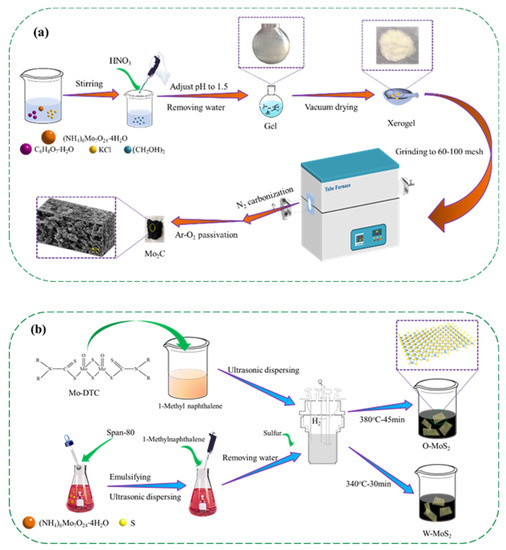
Figure 1.
Schematic illustration of the preparation process of the catalysts, (a) Mo2C, and (b) O-MoS2 and W-MoS2.
XRD measurement was employed to analyze the crystalline structure of the catalysts, with the patterns displayed in Figure 2. Based on the PDF#74-0932 card, the identified diffraction peaks for O-MoS2 and W-MoS2 can be indexed to the hexagonal 2H-MoS2 phase [42]. The weak intensity of peaks at 32.7° and 58.3°, corresponding to the (100) and (110) in-plane diffraction, indicates poor crystallinity and the small crystalline domains of MoS2. Furthermore, the (002) peak representative of the number of stacked layers was weaker in O-MoS2 than that in W-MoS2, indicating that as-synthesized O-MoS2 showed no evident stacking of the MoS2 monolayers along the c-axis while W-MoS2 could be of a multiplayer nature. Based on the Scherrer equation, the mean sizes of W-MoS2 and O-MoS2 were tentatively calculated to be 4.1 and 4.4 nm, respectively.
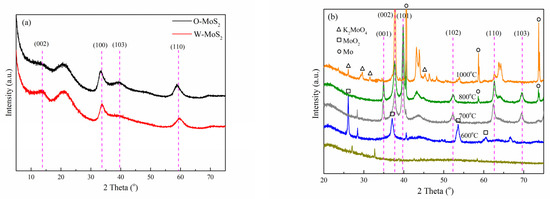
Figure 2.
XRD patterns of catalysts, (a) MoS2, and (b) Mo2C.
For the XRD pattern of Mo2C nanoparticles obtained at different carbonization temperatures, it can be seen that the carbonization was incomplete under 600 °C since the characteristic peaks at 25.95°, 36.94°, 53.44° and 60.19° corresponding to monoclinic molybdenum dioxide (MoO2) were obviously observed. The (001), (002), (101), (102), (110), (103), and (200) peaks of β-Mo2C, which has a hexagonal structure and high thermal stability, began to appear at 700 °C [43]. When the carbonization temperature was increased to 1000 °C, the characteristic diffraction peaks corresponding to K2MoO4 (2θ = 26.09°, 29.65°, 31.53° and 45.35°) and metallic molybdenum (2θ = 40.49°, 58.61° and 73.66°) were clearly visible. Meanwhile, the high temperature could easily lead to the sintering of the active phase, which could destroy its structure and affect the catalytic activity. In this study, Mo2C nanoparticles prepared at a carbonization temperature of 800 °C were selected as the catalyst in the follow-up study to ensure sufficient Mo2C formation and fewer byproducts. The mean size of Mo2C nanoparticles was estimated to be 22.6 nm, approximately.
Figure 3 displays the HRTEM images of O-MoS2, W-MoS2 and Mo2C catalysts. MoS2 presented a uniformly distributed sheet structure with a curved lamella shape. The particle size distribution was illustrated in Figure 4. There was no obvious stacking of O-MoS2 lamellae, which is in good accordance with the XRD analysis. The O-MoS2 exhibited a monolayer structure with lamellae length ranging from 5 to 14.0 nm. By comparison, W-MoS2 possessed a longer lamellae length of 8–18 nm with a stacking number of 5–13. Since the nanocatalyst with a smaller grain size typically facilitates the exposition of edge sites, better catalytic activity could be expected of O-MoS2 [44]. Mo2C samples exhibited various dispersed nanocrystalline particles with the average size of 7–19 nm. The difference between the mean size obtained from XRD and that from TEM could possibly be ascribed to the irregular shape of MoS2 lamellae or Mo2C particle. The agglomeration could be observed in some Mo2C nanoparticles. The d lattice spacing of 0.237 nm was found in Mo2C, assigned to the hexagonal β-Mo2C (002) planes, which further confirms the formation of molybdenum carbide.
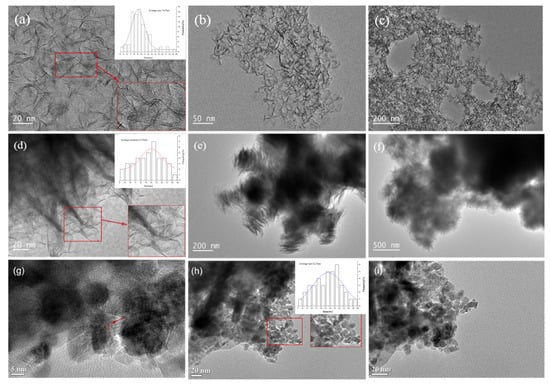
Figure 3.
HRTEM pictures of catalysts, (a–c) O-MoS2, (d–f) W-MoS2, (g–i) Mo2C.
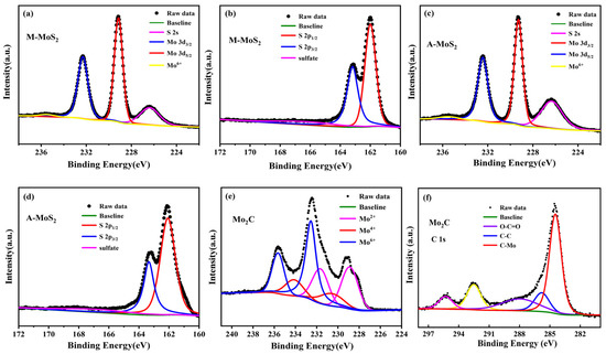
Figure 4.
High-resolution XPS spectra of the Mo 3d (a,c), S 2p (b,d) regions of O-MoS2 and W-MoS2 respectively, and the Mo 3d (e), C 1s (f) regions of Mo2C.
The chemical states for these Mo-based nanoparticles were examined by XPS. All the binding energy was calibrated using the C 1s photoelectron peak at 284.8 eV as a reference. Figure 4 presents the high-resolution XPS spectra of Mo 3d, S 2p for the O-MoS2 and W-MoS2, and Mo 3d, C 1s for the Mo2C. In the XPS spectra of the Mo 3d and S 2s region, the two major peaks located at 229.17 and 232.32 eV correspond to Mo4+ 3d5/2 and Mo4+ 3d3/2 of the MoS2, the major peaks at 162.0 and 163.17 eV are attributed to S 2p3/2 and S 2p1/2 of the MoS2, respectively [45,46]. In addition to the Mo 3d signals, a peak at 226.3 eV belonging to the S 2s orbital was observed. Obviously, a small peak at 235.8 eV can be ascribed to the Mo6+ of MoO3, which was ascribed to the inevitable surface oxidation of MoS2 when exposed in air. The Mo 3d high-resolution element spectrum of Mo2C was deconvoluted into six peaks, in which two peaks at 228.8 eV (3d5/2) and 231.9 eV (3d3/2) can be assigned to Mo2+ in Mo2C, two peaks at 230.1eV and 233.2 eV denote Mo4+ in Mo2C or MoO2 and two peaks at 232.8 eV and 235.9 eV belong to Mo6+ in MoO3 [47]. The appearance of MoO2 and MoO3 is usually caused by the use of inert gas atmosphere with 1% oxygen in the passivation process or the oxidation of carbides exposed to air, which is consistent with previous literature [48,49]. The peaks of 284.4 and 285.7 eV in the spectra of C 1s belong to C-Mo and C-C bonds in Mo2C. The atomic ratio of C/Mo was calculated to be 1:2.08 based on the XPS data, indicating the dominance of Mo2C in the as-synthesized catalyst.
The BET surface areas of the W-MoS2, O-MoS2 and Mo2C were determined to be 51.6, 324.6 and 42 m2/g, respectively. The extremely high surface area of O-MoS2 was much greater than that of W-MoS2 and could be one of the possible reasons for its higher catalytic activity. Even though Mo2C presented a lower surface area than MoS2, it could still display excellent catalytic activity because of its Pt-like nature. The BJH pore size distribution curves of MoS2 and Mo2C are presented in Figure 5. The pore-size distributions revealed that the W-MoS2 and O-MoS2 had only a narrow peak at around 3.2 nm and 9 nm, respectively. Conversely, the Mo2C catalyst showed a narrow pore-size distribution peak at approximately 3.4 nm, and another larger pore distribution broader than 5 nm. Since larger mesopores are much more important for mass transfer resistance for reacting molecules, such a combination on the hierarchical structures is potentially ideal for the catalytic reaction. The hierarchical structures prevent the entry of polycyclic aromatic hydrocarbons, but allow the entry of olefinic substituents. This special pore size distribution could be beneficial for improving the selectivity in the hydrogenation reaction.
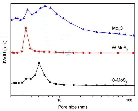
Figure 5.
Pore-size distribution curves of catalyst samples.
3.2. Hydrogenation Activity Measurement in Slurry Oil Surrogate
The hydrogenation treatments of the slurry oil surrogate were carried out at 380 °C with MoS2 and Mo2C nanoparticles. The typical GC-MS results of the products are shown in Figure S1 as supporting information. It can be seen that 1-methylnaphthalene was simultaneously hydrogenated and thermally cracked during the hydrotreating process, and the chromatographic peaks of these derived products were relatively extensive because of the extremely high amount of 1-methylnaphthalene. However, it did not affect the following discussion about the catalytic activity of Mo-based catalysts for the hydrogenation of olefins and sulfur compounds in the present work. The conversions for each molecule contained in the slurry oil surrogate are shown in Figure 6. Over 80% of the olefins were removed by hydrotreatment with the three Mo-based nanoparticles. The conjugated olefins are more difficult to hydrogenate than monoolefins due to the higher aromaticity and larger steric hindrance [7]. Because of the good dispersion and smaller particles, proved by HRTEM, the O-MoS2 exhibited better activity for olefin removal than W-MoS2, although the amount of W-MoS2 was greater [24]. Further enhanced catalytic activity was found for Mo2C, even trans-stilbene had an increased conversion of 92%. The selectivity for hydrogenated products during olefin hydrotreatment is illustrated in Figure 7. It demonstrates that the excellent catalytic performance of Mo2C for olefin removal mainly originates from its activity for hydrogenation. For the three olefins, the 1,3-diphenylethane, ethylbenzene and 2-methyl-heptane selectivity can be up to 93.2%, 96.6% and 99.3%, respectively.
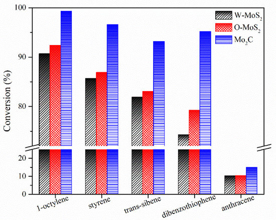
Figure 6.
Conversion of model compounds on various catalysts.
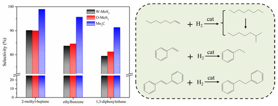
Figure 7.
Main product selectivity and hydrogenation pathway of olefins on various catalysts.
The activity improvement of Mo2C could also be observed for catalyzing sulfur removal and tended to be much stronger. This was consistent with previous reports [40]. The conversion of dibenzothiophene rose from 65% with W-MoS2 to 95% with Mo2C. Anthracene presented the lowest conversion compared with olefins and dibenzothiophene, and there was no great difference for the three catalysts, indicating Mo2C displayed a good selectivity for olefins and dibenzothiophene conversion. Figure 8 shows the product selectivity for anthracene conversion with these three catalysts. It was found that Mo2C facilitated the formation of 9,10-dihydroanthracene, suggesting that Mo2C could limit the anthracene hydrogenation to a mild hydrogenation step and protect it from being deeply hydrogenated. According to the literature [1], the production of a small portion of hydroaromatics could serve as hydrogen donors during the carbonization of FCC slurry oil and benefit the good morphology of coke formation.
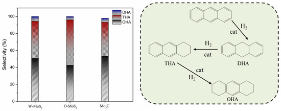
Figure 8.
Product selectivity and hydrogenation pathway of anthracene. DHA, THA and OHA refer to 9,10-dihydroanthracene, 1,2,3,4-tetrahydroanthracene, and 1,2,3,4,5,6,7,8-octahydroanthracene.
3.3. Hydrogenation Activity Evaluation in FCC Slurry Oil
The catalytic performance of these Mo-based catalysts on the hydrotreating of FCC slurry oil were further evaluated. The elemental analysis and molecular weight of FCC slurry oil before and after the hydrotreating process with different catalysts are compared in Table 2. The H/C ratio presented only a slight increase after hydrotreatment and the molecular weight did not change much. It indicates that FCC slurry oil has been subjected to a mild hydrotreating process, which is necessary to preserve the main native polyaromatics components. The major change of FCC slurry oil in the elemental analysis lies in the sulfur content which decreased from 0.41% to approximately 0.22%. A portion of nitrogen was also removed during this process, even though the removal efficiency was lower because of the higher bonding energy of C-N than C-S.
Table 2.
Distribution of C/H/S/N elements in FCC slurry oil before and after hydrotreatment.
Figure 9 shows the 1H-NMR spectra of FCC slurry oil before and after hydrogenation, and the calculated hydrogen distribution is listed in Table 3. The hydrogen type classification was referenced from previous literature [7,50]. A slight decrease of the aromatic hydrogen content (Hcar) was found in this study, suggesting the mild hydrogenation of aromatics [51]. Consequently, the content of naphthenic hydrogen (Hcβ and Hcα) has been raised. As aforementioned, the generation of these naphtheno-aromatics is desirable since they could benefit the hydrogen transfer behavior during the carbonization of SLO [1]. Furthermore, the aliphatic hydrogen of methyl or methylene groups in the α- and γ-position to an aromatic ring was observed to be increased while that in the β-position to an aromatic ring was reduced. It suggests that the thermal cracking reactions of aliphatic carbon chains have occurred, which could be due to the cracking function of these nanoparticles. More importantly, the olefin hydrogen content (Ho) was significantly decreased, indicating the excellent catalytic activity for olefin removal.
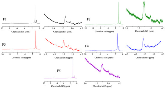
Figure 9.
The 1H-NMR spectra of FCC slurry oil before and after hydrotreatment. The feed FCC slurry oil is designated as F1; FCC after reaction with non-catalyst is designated as F2. FCC after reaction with A-MoS2 is designated as F3; FCC after reaction with M-MoS2 is designated as F4; FCC after reaction with Mo2C is designated as F5.
Table 3.
Hydrogen type distribution in the 1H-NMR spectra of FCC slurry oil before and after hydrotreatment.
To further evaluate the transformation of the FCC slurry oil, the average molecular structural parameters were then calculated based on the modified Brown-Ladner method, the main calculation equations are provided in Table S2 as the supporting information, with the results presented in Table 4. Apparently, even though RA showed a slight decrease because of the hydrogenation reactions, resulting in an increase of RN, there was no significant difference for the fA, fN and fP of hydrotreated oil, proving that the aromatic moiety of SLO was protected from overhydrogenation.
Table 4.
The average molecular structural parameters of FCC slurry oil before and after hydrotreatment.
In order to further investigate olefin removal with the aid of these nanoparticles, the bromine number and diene value were measured. As shown in Figure 10, the catalytic activity of W-MoS2, O-MoS2 and Mo2C to remove olefins was improved successively, which was consistent with the observation with the model compound. With Mo2C, the olefins had significantly decreased from 5.7 to 1.05 gBr2/100 g, and the conjugated olefins were reduced from 2.64 to 0.91 gI2/100 g. Based on the formulation as Equations (1) and (2), the content of olefins can be calculated.
where wo and wco are the content of olefins and conjugated olefins, respectively. VBr and VDi refer to the measured bromine value and diene value, respectively. M is the molecular weight of the sample. The results showed that the feed SLO contained about 21.14% olefins. Among the olefins, the proportion of conjugated olefins could be 27%. As systematically stated by Jiao et al. [10], these olefinic molecules in considerable amounts were extremely reactive in generating free radicals, which would aggravate the internal thermal reactions governing the stability of SLO and affecting the quality of the carbonaceous materials prepared. After hydrotreatment with O-MoS2 and Mo2C, only 5.5% and 3.8% of olefins were left in the SLO.
wo = VBr × M/(2 × 79.9)
wco = VDi × M/253.8
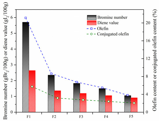
Figure 10.
Bromine numbers and diene values of SLO before and after hydrogenation. The feed FCC slurry oil is designated as F1; FCC after reaction with non-catalyst is designated as F2. FCC after reaction with A-MoS2 is designated as F3; FCC after reaction with M-MoS2 is designated as F4; FCC after reaction with Mo2C is designated as F5.
The removal efficiency of olefins by hydrotreating based on the bromine value and Ho content and that of the conjugated olefins based on diene value are compared in Figure 11. The good agreement of the results by the two indicators suggests that 1H-NMR is an effective and convenient technique for analyzing the olefin content. The conversion of conjugated olefins was found to be much lower than that of the total olefins, leading to the proportion of conjugated olefins to olefins gradually increasing. Compared with MoS2, Mo2C showed the highest catalytic activity for olefin removal, and the conversion of olefins and conjugated olefins could be up to 82% and 64%, respectively.
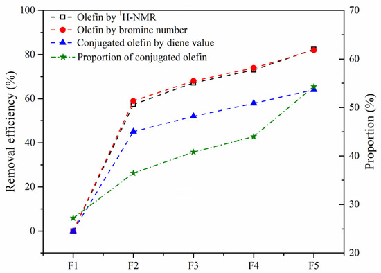
Figure 11.
Removal efficiency of olefins in the SLO. The feed FCC slurry oil is designated as F1; FCC after reaction with non-catalyst is designated as F2. FCC after reaction with A-MoS2 is designated as F3; FCC after reaction with M-MoS2 is designated as F4; FCC after reaction with Mo2C is designated as F5.
To describe the thermal stability of slurry oil, the spot experiment was carried out, with the results displayed in Figure 12. F1 shows obvious dark rings inside the spot indicating the poor stability of the feed oil, which can be mainly attributed to the existence of abundant active olefins. Therefore, the olefinic bonds must be hydrogenated to be removed. Mild hydrogenation treatment alone or with W-MoS2 were not so effective in improving the stability of SLO. In contrast, when O-MoS2 catalysts were added into the reaction system, the stability of the slurry oil was obviously improved, which was attributed to the good dispersion and strong catalytic hydrogenation activity of MoS2. Additionally, the spot experiment of slurry oil under Mo2C showed that almost no dark rings appeared, implying high hydrogenation activity of the Mo2C catalyst which effectively enhanced the thermal stability of SLO.
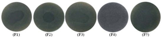
Figure 12.
Spot experiment of FCC slurry oil before and after hydrogenation on various catalysts. The feed FCC slurry oil is designated as F1; FCC after reaction with non-catalyst is designated as F2. FCC after reaction with A-MoS2 is designated as F3; FCC after reaction with M-MoS2 is designated as F4; FCC after reaction with Mo2C is designated as F5.
4. Conclusions
Olefins and sulfur are the major impurities widely distributed in FCC slurry oil (SLO) which seriously deteriorate the preparation and quality of mesophase pitch or needle coke. The development of a hydrotreatment for SLO to remove olefins and sulfur selectively becomes imperative. This work presents the potentiality of dispersed Mo2C and MoS2 nanoparticles as selective hydrotreating catalysts of SLO. Mo2C was synthesized by the carbonization of citric acid, ammonium molybdate and KCl mixtures while MoS2 was prepared from the decomposition of precursors. These catalysts were characterized by XRD, HRTEM, XPS, BJH, and applied to the hydrotreatment of the SLO surrogate with defined components and the real SLO. The results showed that hydrotreating of the SLO surrogate with a very small amount of Mo-based nanoparticles could selectively remove olefins and sulfur without overhydrogenation of polyaromatics. Mo2C exhibited much better activity than MoS2, with 95% of olefins and dibenzothiophene in the surrogate removed. For the real SLO study, approximately 50% sulfur and 82% olefins were removed with Mo2C, and the stability was significantly improved. The calculated structural parameters were changed subtly, proving that the aromatic macromolecules were not affected. Additionally, it was found that the removal efficiency of olefins calculated by bromine number was in good agreement with that obtained by 1H-NMR, suggesting 1H-NMR is an effective and convenient technique to analyze the olefin content for SLO.
Supplementary Materials
The following are available online at https://www.mdpi.com/article/10.3390/nano11102721/s1, Figure S1: The typical chromatogram of products from hydrotreating of SLO surrogate, Table S1: Specification of the chemicals used in this work, Table S2: Equations for the modified Brown-Ladner method.
Author Contributions
Conceptualization, H.L. and A.G.; methodology, H.L., Z.Q. and H.P.; software, H.L. and Z.Q.; validation, H.L., Z.Q., H.P.; investigation, H.L. and S.J.; resources, S.J., F.W. and K.C.; data curation, F.W.; writing—original draft preparation, H.L. and Z.Q.; writing—review and editing, A.G. and Z.W.; visualization, F.W.; supervision, A.G.; project administration, A.G.; funding acquisition, A.G.; K.C. and Z.W. All authors have read and agreed to the published version of the manuscript.
Funding
This work was supported by the National Natural Science Foundation of China (21776313, 21908248), Key Technology Research and Development Program of Shandong (2017GGX70108), the Postgraduate Innovation Project (YCX2021056), Fundamental Research Funds for the Central Universities (19CX02013A and 20CX02206A), Development Fund of State Key Laboratory of Heavy Oil Processing and the China National Petroleum Corporation (PRIKY19022).
Data Availability Statement
The data presented in this study are available on request from the corresponding author.
Conflicts of Interest
The authors declare no conflict of interest.
References
- Lin, C.; Wang, L.; Wu, S.; Zhou, R.; Zeng, X.; Zhang, J.; Duan, L. Synergistic effect of hydrogen transfer ability on the co-carbonization of different FCC slurry oil fractions. Energy Fuels 2019, 33, 9654–9660. [Google Scholar] [CrossRef]
- Guo, A.; Wang, F.; Jiao, S.; Ibrahim, U.K.; Liu, H.; Chen, K.; Wang, Z. Mesophase pitch production from FCC slurry oil: Optimizing compositions and properties of the carbonization feedstock by slurry-bed hydrotreating coupled with distillation. Fuel 2020, 262, 116639. [Google Scholar] [CrossRef]
- Li, P.; Xiong, J.; Ge, M.; Sun, J.; Zhang, W.; Song, Y. Preparation of pitch-based general purpose carbon fibers from catalytic slurry oil. Fuel Process. Technol. 2015, 140, 231–235. [Google Scholar] [CrossRef]
- Lou, B.; Liu, D.; Qiu, Y.; Fu, Y.; Guo, S.; Yu, R.; Gong, X.; Zhang, Z.; He, X. Modified effect on properties of mesophase pitch prepared from various twostage thermotreatments of FCC decant oil. Fuel 2021, 284, 119034. [Google Scholar] [CrossRef]
- Tanabe, K.; Takada, T.; Newman, B.A.; Satou, M.; Hattor, H. Hydrotreating of FCC decant oil as a needle coke feedstock. J. Jpn. Inst. Energy 1996, 75, 916–924. [Google Scholar] [CrossRef][Green Version]
- Jiao, S.; Guo, A.; Wang, F.; Yu, Y.; Bernard, W.B.; Liu, H.; Chen, K.; Liu, D.; Wang, Z.; Sun, L. Sequential pretreatments of an FCC slurry oil sample for preparation of feedstocks for high-value solid carbon materials. Fuel 2021, 285, 119169. [Google Scholar] [CrossRef]
- Jiao, S.; Guo, A.; Wang, F.; Chen, K.; Liu, H.; Ibrahim, U.K.; Wang, Z.; Sun, L. Effects of olefins on mesophase pitch prepared from fluidized catalytic cracking decant oil. Fuel 2020, 262, 116671. [Google Scholar] [CrossRef]
- Noda, T.; Kamiya, K.; Inagaki, M. Effect of pressure on graphitization of carbon. I. heat treatment of soft carbon under 1, 3 and 5 kbar. B. Chem. Soc. Jpn. 1968, 41, 485–492. [Google Scholar] [CrossRef]
- Fujimoto, K.I.; Mochida, I.; Todo, Y.; Oyama, T.; Yamashita, R.; Marsh, H. Mechanism of puffing and the role of puffing inhibitors in the graphitization of electrodes from needle cokes. Carbon 1989, 27, 909–917. [Google Scholar] [CrossRef]
- Jiao, S.; Wang, F.; Wang, L.; Bernard, W.B.; Liu, H.; Chen, K.; Guo, A.; Sun, L.; Wang, Z. Systematic identification and distribution analysis of olefins in FCC slurry oil. Energy 2022, 239, 121959. [Google Scholar] [CrossRef]
- Oh, Y.; Shin, J.; Noh, H.; Kim, C.; Kin, Y.S.; Lee, Y.K. Selective hydrotreating and hydrocracking of FCC light cycle oil into high value light aromatic hydrocarbons. Appl. Catal. A-Gen. 2019, 577, 86–98. [Google Scholar] [CrossRef]
- Xu, C.; Yang, C. Petroleum Refining Engineering, 4th ed.; Petroleum Industry Press: Beijing, China, 2009; pp. 247–299. [Google Scholar]
- Hancsók, J.; Marsi, G.; Kasza, T.; Kalló, D. Hydrogenation of the aromatics and olefins in FCC gasoline during deep desulphurisation. Top. Catal. 2011, 54, 1102–1109. [Google Scholar] [CrossRef]
- Kaluža, L. Activity of transition metal sulfides supported on Al2O3, TiO2 and ZrO2 in the parallel hydrodesulfurization of 1-benzothiophene and hydrogenation of 1-methyl-cyclohex-1-ene. React. Kinet. Mech. Cat. 2015, 114, 781–794. [Google Scholar] [CrossRef]
- Kaluža, L.; Gulková, D. Effect of promotion metals on the activity of MoS2/ZrO2 catalyst in the parallel hydrodesulfurization of 1-benzothiophene and hydrogenation of 1-methyl-cyclohex-1-ene. React. Kinet. Mech. Cat. 2016, 118, 313–324. [Google Scholar] [CrossRef]
- Escallon, M.M.; Fonseca, D.A.; Schobert, H.H. Characterization of hydrotreated decant oils. Effect of different severities of hydrotreating on decant oil chemical composition. Energy Fuels 2013, 27, 478–486. [Google Scholar] [CrossRef]
- Wincek, R.T.; Abrahamson, J.P.; Eser, S. Hydrodesulfurization of fluid catalytic cracking decant oils in a laboratory flow reactor and effect of hydrodesulfurization on subsequent coking. Energy Fuels 2016, 30, 6281–6289. [Google Scholar] [CrossRef]
- Abrahamson, J.P.; Wincek, R.T.; Eser, S. Effects of catalyst properties on hydrodesulfurization activity for sulfur removal from fluid catalytic cracking decant oils. Energy Fuels 2016, 30, 7173–7179. [Google Scholar] [CrossRef]
- Eser, S.; Wang, G.H. A laboratory study of a pretreatment approach to accommodate high-sulfur FCC decant oils as feedstocks for commercial needle coke. Energy Fuels 2007, 21, 3573–3582. [Google Scholar] [CrossRef]
- Costa, P.D.; Potvin, C.; Manoli, J.M.; Lemberton, J.L.; Pérot, G.; Djéga-Mariadassou, G. New catalysts for deep hydrotreatment of diesel fuel: Kinetics of 4, 6-dimethyldibenzothiophene hydrodesulfurization over alumina-supported molybdenum carbide. J. Mol. Catal. A Chem. 2002, 184, 323–333. [Google Scholar] [CrossRef]
- Xu, Y.; Wang, R.; Wang, J.; Li, J.; Jiao, T.; Liu, Z. Facile fabrication of molybdenum compounds (Mo2C.; MoP and MoS2) nanoclusters supported on N-doped reduced graphene oxide for highly efficient hydrogen evolution reaction over broad pH range. Chem. Eng. J. 2021, 417, 129233. [Google Scholar] [CrossRef]
- Sousa, L.A.; Zotin, J.L.; Silva, V.T. Hydrotreatment of sunflower oil using supported molybdenum carbide. Appl. Catal. A-Gen. 2012, 449, 105–111. [Google Scholar] [CrossRef]
- Duan, Y.; Liu, Y.; Chen, Z.; Liu, D.; Yu, E.; Zhang, X.; Fu, H.; Fu, J.; Zhang, J.; Du, H. Amorphous molybdenum sulfide nanocatalysts simultaneously realizing efficient upgrading of residue and synergistic synthesis of 2D MoS2 nanosheets/carbon hierarchical structures. Green Chem. 2020, 22, 44–53. [Google Scholar] [CrossRef]
- Al-Attas, T.A.; Ali, S.A.; Zahir, M.H.; Xiong, Q.G.; Al-Bogami, S.A.; Malaibari, Z.O.; Razzak, S.A.; Hossain, M.H. Recent advances in heavy oil upgrading using dispersed catalysts. Energy Fuels 2019, 33, 7917–7949. [Google Scholar] [CrossRef]
- Zhang, H.; Lin, H.; Zheng, Y. Hydrotreatment of light cycle oil over a dispersed MoS2 catalyst. Int. J. Chem. React. Eng. 2016, 14, 703–711. [Google Scholar] [CrossRef]
- Deng, W.; Lu, J.; Li, C. Hydrogenation behavior of bicyclic aromatic hydrocarbons in the presence of a dispersed catalyst. Energy Fuels 2015, 29, 5600–5608. [Google Scholar] [CrossRef]
- Hu, Y.; Da, Z.; Wang, Z. Hydrogenation conversion of phenanthrene over dispersed Mo-based catalysts. China Pet. Process. Petrochem. Technol. 2015, 17, 7–14. [Google Scholar]
- Dutta, R.P.; Schobert, H.H. Hydrogenation/dehydrogenation of polycyclic aromatic hydrocarbons using ammonium tetrathiomolybdate as catalyst precursor. Catal. Today 1996, 31, 65–77. [Google Scholar] [CrossRef]
- Mladenović, D.; Vujković, M.; Mentus, S.; Santos, D.M.F.; Rocha, R.P.; Sequeira, C.A.C.; Figueiredo, J.L.; Šljukić, B. Carbon-supported Mo2C for oxygen reduction reaction electrocatalysis. Nanomaterials 2020, 10, 1805. [Google Scholar] [CrossRef]
- Li, Y.; Yin, Z.; Liu, X.; Cui, M.; Chen, S.; Ma, T. Current progress of molybdenum carbide-based materials for electrocatalysis: Potential electrocatalysts with diverse applications. Mater. Today Chem. 2021, 19, 100411. [Google Scholar] [CrossRef]
- Szymańska-Kolasa, A.; Lewandowski, M.; Sayag, C.; Djéga-Mariadassou, G. Comparison of molybdenum carbide and tungsten carbide for the hydrodesulfurization of dibenzothiophene. Catal. Today 2007, 119, 7–12. [Google Scholar] [CrossRef]
- Dhandapani, B.; Clair, T.S.; Oyama, S.T. Simultaneous hydrodesulfurization, hydrodeoxygenation, and hydrogenation with molybdenum carbide. Appl. Catal. A-Gen. 1998, 168, 219–228. [Google Scholar] [CrossRef]
- Luo, Y.; Jin, G. Catalytic behaviors of molybdenum carbide catalyst for quinoline hydrodenitrogenation (HDN). Ind. Catal. 2009, 17, 16–19. [Google Scholar]
- Gavrilova, N.; Myachina, M.; Nazarov, V.; Skudin, V. Simple synthesis of molybdenum carbides from molybdenum blue nanoparticles. Nanomaterials 2021, 11, 873. [Google Scholar] [CrossRef]
- Dubrovskii, A.R.; Kuznetsov, S.A.; Rebrov, E.V.; Schouten, J.C. Catalytic Mo2C coatings for the water gas shift reaction: Electrosynthesis in molten salts. Kinet. Catal. 2008, 49, 594–598. [Google Scholar] [CrossRef]
- Kuznetsov, S.A.; Dubrovskii, A.R.; Rebrov, E.V.; Schouten, J.C. Electrochemical synthesis of Mo2C catalytical coatings for the water-gas shift reaction. Z. Naturforsch. A 2007, 62, 647–654. [Google Scholar] [CrossRef][Green Version]
- Osman, A.I.; Abu-Dahrieh, J.K.; Nikolay, C.; Fernandez-Garcis, J.; Walker, D.; Walton, R.I.; Rooney, D.W.; Rebrov, E. A highly active and synergistic Pt/Mo2C/Al2O3 catalysts for water-gas shift reaction. Mol. Catal. 2018, 455, 38–47. [Google Scholar] [CrossRef]
- Dubrovskiy, A.R.; Rebrov, E.V.; Kuznetsov, S.A.; Schouten, J.C. A microstructured reactor/heat-exchanger for the water–gas shift reaction operated in the 533–673 K range. Catal. Today 2009, 147, S198–S203. [Google Scholar] [CrossRef]
- Aegerter, P.A.; Qiugley, W.; Simpson, G.J.; Ziegler, D.D.; Logan, J.W.; McCrea, K.R.; Glazier, S.; Bussell, M.E. Thiophene hydrodesulfurization over alumina-supported molybdenum carbide and nitride catalysts: Adsorption sites, catalytic activities, and nature of the active surface. J. Catal. 1996, 164, 109–121. [Google Scholar] [CrossRef]
- Sajkowski, D.J.; Oyama, S.T. Catalytic hydrotreating by molybdenum carbide and nitride: Unsupported Mo2N and Mo2C/A12O3. Appl. Catal. A-Gen. 1996, 134, 339–349. [Google Scholar] [CrossRef]
- Qiu, Z.; Li, Q.; Ma, S.; Li, Z. Effect of final carbonization temperature on catalytic performance of β-Mo2C in quinoline hydrodenitrogenation. J. Fuel Chem. Technol. 2020, 48, 357–368. [Google Scholar]
- Watanabe, I.; Otake, M.; Yoshimoto, M.; Sakanishi, K.; Korai, Y.; Mochida, I. Behaviors of oil-soluble molybdenum complexes to form very fine MoS2 particles in vacuum residue. Fuel 2002, 81, 1515–1520. [Google Scholar] [CrossRef]
- Wang, D.; Liu, T.; Wang, J.; Wu, Z. N, P (S) Co-doped Mo2C/C hybrid electrocatalysts for improved hydrogen generation. Carbon 2018, 139, 845–852. [Google Scholar] [CrossRef]
- Li, M.; Wang, D.; Li, J.; Pan, Z.; Ma, H.; Jiang, Y.; Tian, Z. Facile hydrothermal synthesis of MoS2 nano-sheets with controllable structures and enhanced catalytic performance for anthracene hydrogenation. RSC Adv. 2016, 6, 71534–71542. [Google Scholar] [CrossRef]
- Rao, C.N.R.; Nag, A. Inorganic analogues of graphene. Eur. J. Inorg. Chem. 2010, 2010, 4244–4250. [Google Scholar] [CrossRef]
- Baker, M.A.; Gilmore, R.; Lenardi, C.; Gissler, W. XPS investigation of preferential sputtering of S from MoS2 and determination of MoSx stoichiometry from Mo and S peak positions. Appl. Surf. Sci. 1999, 150, 255–262. [Google Scholar] [CrossRef]
- Wang, F.; Zhang, W.; Jiang, J.; Xu, J.; Zhai, Q.; Wei, L.; Long, F.; Liu, C.; Liu, P.; Tan, W.; et al. Nitrogen-rich carbon-supported ultrafine MoC nanoparticles for the hydrotreatment of oleic acid into diesel-like hydrocarbons. Chem. Eng. J. 2020, 382, 122464. [Google Scholar] [CrossRef]
- Kim, M.; Kim, S.; Song, D.; Oh, S.; Chang, K.J.; Cho, E. Promotion of electrochemical oxygen evolution reaction by chemical coupling of cobalt to molybdenum carbide. Appl. Catal. B Environ. 2018, 227, 340–348. [Google Scholar] [CrossRef]
- Liu, K.; Cao, Y.; Yang, S.; Wu, C.; Zhang, Z.; Zhang, Q.; Zhang, H. Molybdenum carbide promoted cobalt as an efficient catalyst for selective hydrogenation. Ind. Eng. Chem. Res. 2020, 59, 14267–14277. [Google Scholar] [CrossRef]
- Winschel, R.A.; Robbins, G.A.; Burke, F.P. Correlation of microautoclave and 1H n.m.r. measurements of coal liquefaction solvent quality. Fuel 1986, 65, 526–532. [Google Scholar] [CrossRef]
- Abrahamson, J.P.; Wincek, R.T.; Eser, S. Scheme for hydrotreatment of fluid catalytic cracking decant oil with reduced hydrogen consumption and high needle coke yield upon carbonization. Energy Fuels 2016, 30, 8150–8155. [Google Scholar] [CrossRef]


Publisher’s Note: MDPI stays neutral with regard to jurisdictional claims in published maps and institutional affiliations. |
© 2021 by the authors. Licensee MDPI, Basel, Switzerland. This article is an open access article distributed under the terms and conditions of the Creative Commons Attribution (CC BY) license (https://creativecommons.org/licenses/by/4.0/).