Abstract
High-definition transcranial direct current stimulation (HD-tDCS) is a promising non-invasive neuromodulation technique, which has been widely used in the clinical intervention and treatment of neurological or psychiatric disorders. Sintered Ag/AgCl electrode has become a preferred candidate for HD-tDCS, but its service life is very short, especially for long-term anodal stimulation. To address this issue, a novel highly durable conductive carbon/silver/silver chloride composite (C/Ag/AgCl) electrode was fabricated by a facile cold rolling method. The important parameters were systematically optimized, including the conductive enhancer, the particle size of Ag powder, the C:Ag:PTFE ratio, the saline concentration, and the active substance loading. The CNT/Ag/AgCl-721 electrode demonstrated excellent specific capacity and cycling performance. Both constant current anodal polarization and simulated tDCS measurement demonstrated that the service life of the CNT/Ag/AgCl-721 electrodes was 15-16 times of that of sintered Ag/AgCl electrodes. The much longer service life can be attributed to the formation of the three-dimensional interpenetrating conductive network with CNT doping, which can maintain a good conductivity and cycling performance even if excessive non-conductive AgCl is accumulated on the surface during long-term anodal stimulation. Considering their low cost, long service life, and good skin tolerance, the proposed CNT/Ag/AgCl electrodes have shown promising application prospects in HD-tDCS, especially for daily life scenarios.
1. Introduction
Transcranial direct current stimulation (tDCS) is a non-invasive neuromodulation technique that uses a constant low-intensity direct current (1~2 mA) to regulate the activity of cortical neurons [1,2,3,4]. In recent years, tDCS has been widely used in the clinical intervention and treatment of epilepsy [5,6,7,8], depression [9,10] stroke [11,12], and other neurological or psychiatric disorders [13,14,15,16,17,18]. Compared with other non-invasive brain stimulation techniques, tDCS has the advantages of high safety, good tolerance, convenient use, and less side effects [19,20,21,22,23]. The tDCS devices are often portable and can be integrated into existing wearable devices, so as to extend the application scenarios from traditional clinical laboratories to daily life. Many case studies have also confirmed the necessity of home tDCS treatment [24,25,26,27].
As an indispensable component of the tDCS device, tDCS electrodes (usually including anode and cathode) are mainly responsible for injecting the stimulation current into skin [17,28]. Two tDCS electrodes are placed on the specific scalp locations to form a loop to deliver a constant current into stimulated sites. In clinical practice, tDCS electrodes are often divided into two categories. The first category is conventional inert electrodes. The typical inert electrodes are stainless steel and conductive rubber electrodes [29], which are usually used with a saline-soaked sponge as the electrolyte [30,31]. Obviously, these inert electrodes cannot undergo any electrochemical reactions. During tDCS, the electrolysis of NaCl solution often occurs [32], which may cause a pH change of the skin tissue around the tDCS electrode, thus increasing the risk of skin irritation and injury. Due to the charge accumulation at the electrode/electrolyte interface, these inert electrodes cannot deliver high current density. Therefore, the area of inert electrodes has to be quite large (25~35 cm2), which severely sacrifices the spatial resolution of tDCS [33,34,35]. In general, the current density of inert electrodes is less than 0.08 mA cm−2.
In order to improve the spatial resolution, the second category (viz. sintered Ag/AgCl electrodes) that tolerate high current density is usually used. For example, small-sized sintered Ag/AgCl electrodes (less than about 2 cm2), together with conductive gels, are frequently used in HD-tDCS [36,37,38]. A representative 4 × 1 HD-tDCS electrode configuration consists of a single anode placed on the region of interest and four surrounding cathodes [31,35,39]. Such an electrode configuration decreases the contact area, and improves the tolerable stimulated current density and spatial resolution significantly [28]. The electrode can tolerate high current density up to 1 mA cm−2 roughly, which is more than 12 times that of inert electrodes (0.08 mA cm−2). Due to high spatial resolution and excellent tolerance to high current density, the sintered Ag/AgCl electrodes have become the preferred choice for HD-tDCS. Unlike inert electrodes, a fast and reversible electrochemical reaction occurs at the sintered Ag/AgCl electrode/electrolyte interface [40,41,42,43], allowing high current density pass through. Therefore, the interface impedance between electrode and electrolyte (i.e., saline, conductive gels) is very low [44]. In addition, the electrolysis of conductive gels hardly occurs, which effectively avoids the pH change of the skin tissue around the electrodes and reduces the risk of skin damage.
However, the sintered Ag/AgCl electrodes often suffer from the issue of a short service life, especially for successive anodal HD-tDCS. Although the sintered Ag/AgCl electrodes were randomly used as an anode or a cathode in clinical practice, the non-conductive AgCl was still accumulated on the electrode surface after multiple anodal HD-tDCS [32,45], leading to an increase in electrode impedance and stimulation failure eventually. In addition, the non-uniform change in surface impedance may affect the stimulation electric field and the stimulation efficacy [46]. Langenbach et al. [46] found that repeated anodal HD-tDCS for eight times might render sintered Ag/AgCl electrodes unreliable due to the high impedance. Alternating use the electrodes as an anode or a cathode might be a potential solution to this problem. However, most clinical users tend to use the sintered Ag/AgCl electrodes repeatedly for economical and logistical reasons [46,47]. Moreover, the repeated use of sintered Ag/AgCl electrodes is more suitable for non-clinical scenarios because of their low cost and convenience [24,26]. For the purpose of repeated use, developing highly durable and good performance non-polarized tDCS electrodes is highly desirable.
Herein, a highly durable conductive carbon/silver/silver chloride composite (C/Ag/AgCl) electrode was fabricated for HD-tDCS. The conductive carbon doped in Ag/AgCl can maintain good conductivity and specific capacity even if non-conductive AgCl is excessively accumulated on the electrode surface during long-term anodal stimulation. In addition, doping conductive carbon can also improve the redox reversibility, ensuring a better cycle performance. These above two effects of doping conductive carbon can prolong the service life of tDCS electrodes synergistically. The C/Ag/AgCl electrode was fabricated by a facile cold rolling method, with conductive carbon, Ag powder, and polytetrafluoroethylene (PTFE) as the conductive enhancer, active substance, and binder, respectively. The important parameters, including the conductive enhancer, the particle size of Ag powder, the C:Ag:PTFE ratio, the saline concentration, and the active substance loading, were systematically optimized. Thus, the carbon nanotube/silver/silver chloride (CNT/Ag/AgCl-721) electrode demonstrated satisfactory specific capacity and cycling performance. The service life of the CNT/Ag/AgCl electrode was investigated by constant current anodal polarization and simulated tDCS measurement. Moreover, the preliminary assessment of skin tolerance of the CNT/Ag/AgCl-721 electrode was also carried out.
2. Materials and Method
2.1. Chemicals and Materials
Silver nitrate, sodium citrate, sodium borohydride, sodium chloride, isopropanol, and ethanol were analytical grade and purchased from Sinopharm Chemical Reagent Co. Ltd. (Shanghai, China). From Aladdin Reagent Inc. (Shanghai, China), 60 wt.% PTFE was purchased. Industrial-grade CNTs (outer diameter of 50 nm, inner diameter of 20~30 nm, and length of 10~30 μm) were supplied by Tanfeng Graphene Technology Co. Ltd. (Suzhou, China). Commercial 2 μm silver powders were purchased from the Beijing Nonferrous Metals Research Institute (Beijing, China). Ketjenblack (KB), Super P and KS-6 commercial conductive carbon black were supplied by the Wuhan Battery Factory (Wuhan, China). Sintered Ag/AgCl electrodes (outer diameter of 12 mm, inner diameter of 6 mm, and thickness of 1 mm) and GT10 conductive gels (~3.0 wt.% NaCl) were bought from Wuhan Greentek Pty. Ltd. (Wuhan, China).
2.2. Preparation of C/Ag/AgCl Electrodes
Silver powders were synthesized by the chemical reduction of silver nitrate with sodium borohydride as reductant. In brief, 0.1 mol of silver nitrate and 0.2 mol of sodium citrate were completely dissolved into 1 L of deionized water under stirring at a low temperature (0~5 °C). An amount of 1.0 mol of sodium borohydride was also dissolved into another 100 mL of deionized water under an ice water bath. Then, the as-obtained sodium borohydride solution was added dropwise to the silver nitrate solution, and a black precipitate was formed immediately. Afterwards, the black precipitate was suction filtered, washed and dried to obtain silver powder. Different sizes of silver powders (0.1 and 0.5 μm) were prepared by controlling the dropping rate of sodium borohydride.
The C/Ag/AgCl electrodes were fabricated by a cold rolling method, with Ag powder, conductive carbon, and PTFE as the active substance, conductive enhancer and binder, respectively. Firstly, a suitable amount of Ag powder, conductive carbon and PTFE was mixed and ground uniformly. Then, a suitable volume of isopropanol (the mass ratio of isopropanol:Ag powder plus conductive enhancer = 2:1) was added into the above solid mixture and stirred to form thick paste. Then, the as-obtained thick pastes were rolled to a thick film by a YLJ-15T roll squeezer machine (Jingke Materials Pty. Ltd., Hefei, China). The as-obtained film was dried in a vacuum oven at 60 °C overnight, and then cut into many discs with the required size (diameter of 12 mm, thickness of 0.5 mm). The discs were pressed on the titanium mesh, and silver wires were inserted into the electrode discal for subsequent signal transmission. One side of the electrode was encapsulated by epoxy resin. It was noted that the initial active substance of pure Ag was converted into Ag/AgCl when in contact with aqueous electrolyte solution (such as saline). In addition, Ag/AgCl was also gradually formed on the electrode surface during charging (or anodal stimulations). Therefore, the electrode was nominated as the carbon/silver/silver chloride composite (C/Ag/AgCl) electrode.
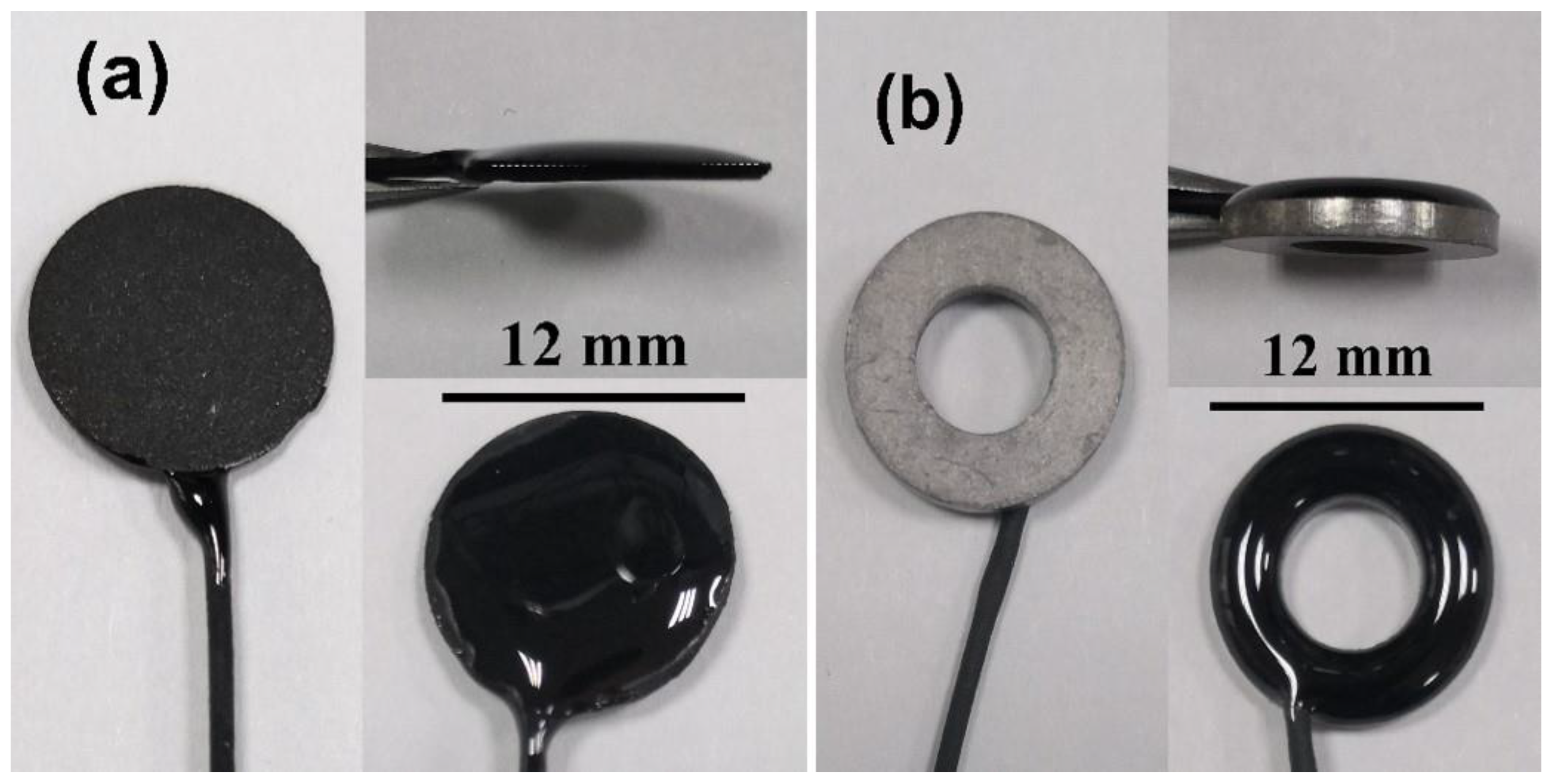
The contact area of C/Ag/AgCl electrodes is 1.32 ± 0.21 cm2. Sintered Ag/AgCl electrodes were also used for comparison, and their contact areas are 1.41 ± 0.08 cm2. The photos of the C/Ag/AgCl and sintered Ag/AgCl electrodes are shown in Figure 1.
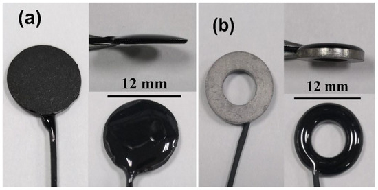
Figure 1.
Photos of the (a) C/Ag/AgCl and (b) sintered Ag/AgCl electrodes.
2.3. Optimization of the Preparation of C/Ag/AgCl
To pursue high durability and good performance, the conductive enhancer, particle size of Ag powder, the component mass ratio (Ag:C:PTFE), the saline concentration and the active substance loading were optimized systematically. In this section, the important parameters for fabricating the C/Ag/AgCl electrodes are summarized in Table 1.

Table 1.
Parameters for the optimization of fabrication of the C/Ag/AgCl electrodes.
2.4. Material Characterization
The morphologies and crystalline phases of the as-obtained Ag powders and CNT/Ag/AgCl-721 were investigated by scanning electron microscopy (SEM) and powder X-ray diffraction (XRD). The SEM images were collected from a Merlin Compact scanning electron microscope (Carl ZEISS, Jena, Germany). XRD measurements were carried out by an XRD-6000 diffractometer (Shimadzu, Tokyo, Japan) operating at 30 kV and 30 mA with Cu Kα radiation (λ = 1.54056° A). Scans were typically carried out from 10 to 90° with a scan rate of 5° min−1.
2.5. Electrochemical Measurements
Three-electrode configuration was used in all electrochemical experiments unless otherwise stated, consisting of a C/Ag/AgCl or sintered Ag/AgCl electrode, a carbon electrode, and a saturated Ag/AgCl electrode as the working electrode, the counter electrode and the reference electrode, respectively. The electrolyte was 3.0 wt.% saline unless otherwise stated. The constant current charging was performed by a Neware tester (Shenzhen Newell company, Shenzhen, China), with a charging current of 2 mA and cut-off voltage of 0.5 V. The plots of electrode potential versus time were recorded. The specific capacity can be estimated by dividing the product of charging current and time by the mass of active substance.
2.6. Simulated tDCS Measurement
During simulated tDCS measurement, an agar block was used as a skin phantom since the electrical properties are similar to real skin. In addition, 0.9% NaCl solution can simulate the subcutaneous tissue well [40]. The agar skin phantom was prepared as follows. Firstly, 1.0 g of agar powder was added into 50 mL of heated 0.9 wt.% NaCl solution, and was stirred until the agar was completely dissolved. Then, the mixture was cooled to room temperature to form an agar block [40]. A two-electrode configuration was used for simulated tDCS experiments, consisting of two CNT/Ag/AgCl-721 electrodes as the working and counter electrodes, respectively. These two electrodes were placed on the surface of the agar skin phantom, at the center-to-center distance of 5 cm, approximately. An amount of 1.5 mL of GT10 conductive gels were injected between the electrode and agar block. The constant anodal current of 2 mA was applied to the two electrodes by an Autolab PGSTAT128N potentiostat (Metrohm Autolab BV, Utrecht, the Netherlands), and the measurements were automatically terminated when the output voltage reached 10 V.
2.7. Preliminary Investigation of Skin Tolerance
Ten heathy volunteers (four females and six males, age between 21 and 35 years) were enrolled for the preliminary investigation of skin tolerance. The experimental protocol was approved by the Research Ethics Committee of Wuhan University, China, and written informed consent was obtained from all volunteers. Two CNT/Ag/AgCl-721 electrodes were placed on the right forearm of volunteers by an elastic cloth strip, with the center-to-center distance of 5 cm. GT10 conductive gels were applied between the electrode and skin. The HD-tDCS was applied to the skin for 30 s using a commercial stimulator (tDCS Mini CT, Soterix Medical Inc., New York, NY, USA) [48,49]. We asked the volunteers whether or not—in their opinion—they felt obvious irritation during tDCS with the CNT/Ag/AgCl-721 electrodes and we also collected their other comments regarding the skin sensations [50,51]. After stimulation, the skin under the tDCS electrodes was carefully examined.
3. Results and Discussions
3.1. Physical Characterization of Ag Powders
Nano-Ag powders with different particle sizes were prepared by controlling the dropping rate of sodium borohydride into a silver nitrate solution. Figure 2 shows the SEM images of nano-Ag and commercial Ag powders. As seen from Figure 2a,b, the flake-like Ag nanoparticles are uniformly dispersed with the average sizes of 100 nm and 500 nm, respectively. In contrast, the commercial Ag powders exhibit non-uniform and irregular shapes, composed of a large number of nano-silver flakes and a small number of micron-sized silver flakes (Figure 2c).
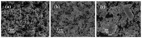
Figure 2.
SEM images of 100 nm (a), 500 nm (b) and commercial 2 μm (c) Ag powders.
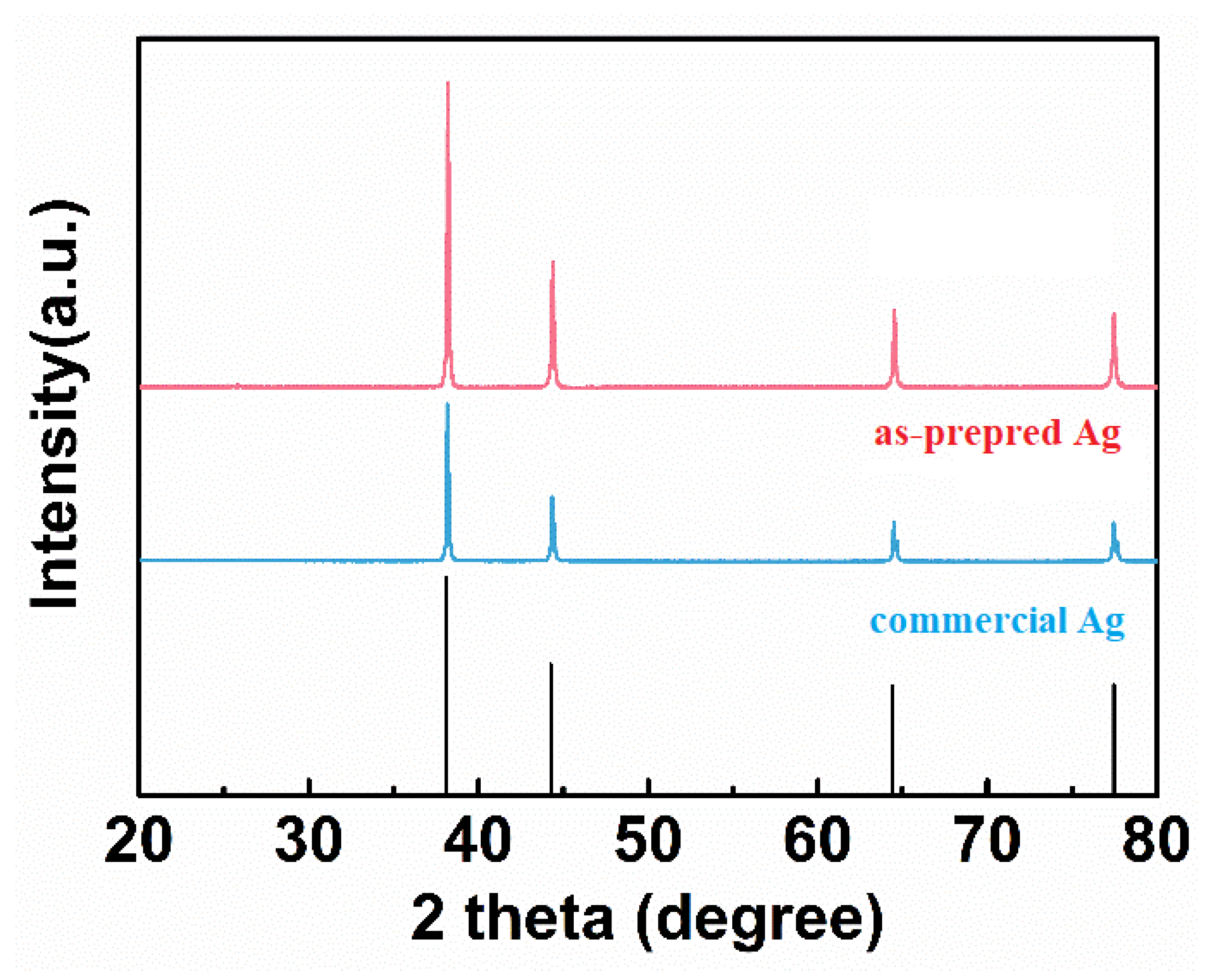
Figure 3 shows the XRD patterns of the as-prepared and commercial Ag powders. The apparent diffraction peaks at 38.1°, 44.3°, 64.4°, 77.4°, and 81.5° are observed in both the as-prepared and commercial Ag powders, which can be well assigned to (111), (200), (220), (311) and (222) facets of cubic Ag (JCPDS No.87-0597). Moreover, there is no obvious impurity peak, indicating that high-purity silver powders were synthesized successfully.
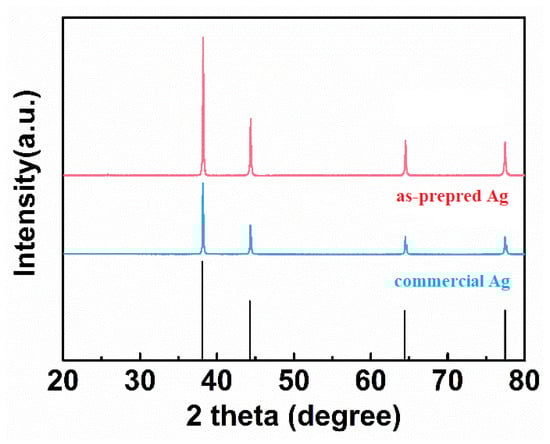
Figure 3.
XRD patterns of the as-prepared and commercial Ag powders.
3.2. Optimization of Preparation of C/Ag/AgCl Electrodes
Anodal/cathodal tDCS are very similar to the constant current charging/discharging processes. Therefore, the durations of charging/discharging represent the service life of tDCS electrodes. For HD-tDCS applications, the stimulation current and the mass of active substance is constant; therefore, the specific capacity directly reflects the service life. In this section, the specific capacity and cycling performance under different conditions was investigated for optimizing the preparation of C/Ag/AgCl electrodes.
3.2.1. Optimization of Conductive Enhancer
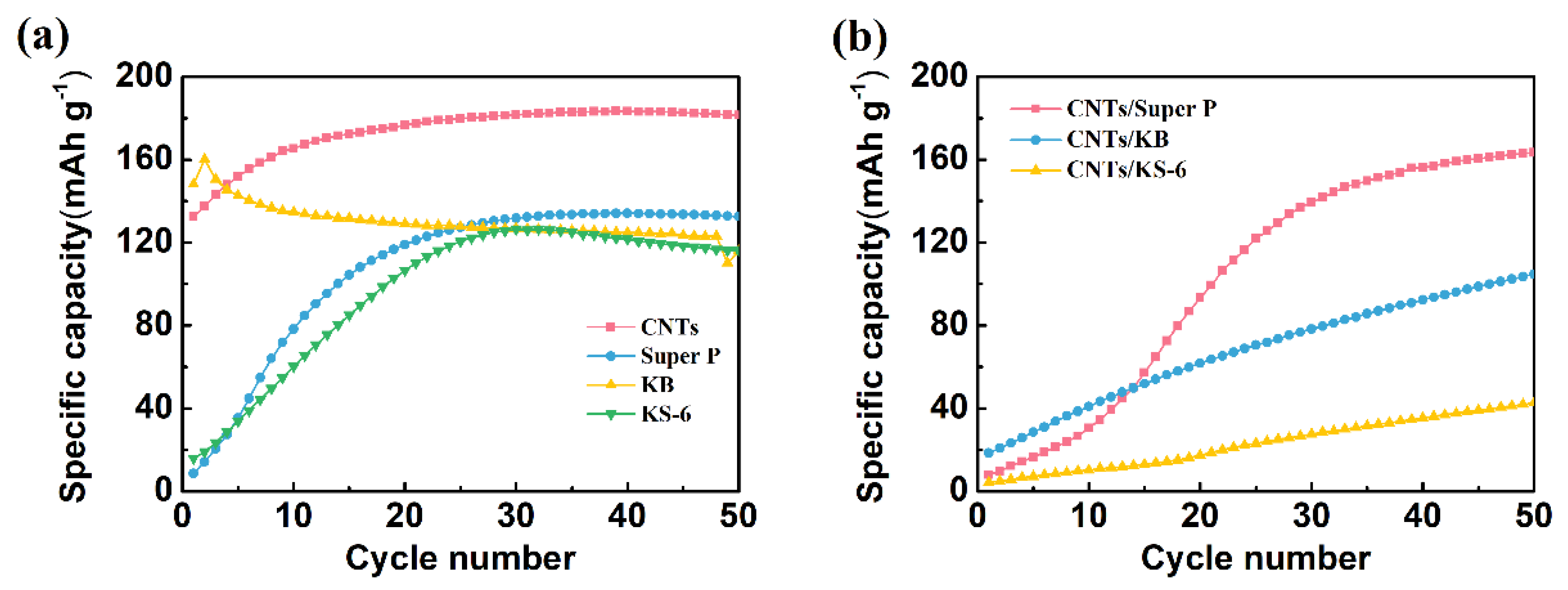
Four types of conductive carbon materials commonly used in batteries (including KS-6, Super P, KB and CNTs) were doped into the Ag powders. Then, the specific capacity of these four types of electrodes was compared. As shown in Figure 4a, the KB/Ag/AgCl electrode displays the highest specific capacity (160 mAh g−1) at the first cycle. However, its specific capacity degrades quickly, and drops down to 123 mAh g−1 after 50 cycles of charging. At the first cycle, the specific capacity of the CNT/Ag/AgCl electrode is 133 mAh g−1. To our surprise, its specific capacity gradually increases with the increase in the number of cycles, and achieves plateau (183 mAh g−1) at about 25 cycles, probably due to a rapid electrode activation process. In contrast, the specific capacity of both KS-6/Ag/AgCl and Super P/Ag/AgCl is very low. It must take a longer time to activate the electrode and maintain relatively high and stable specific capacity (about 130 mAh g−1). Obviously, these two tDCS electrodes are not suitable for practical applications. For the durable HD-tDCS applications, CNTs were preliminary selected as the conductive enhancers.

Figure 4.
Charging cycling performance of the C/Ag/AgCl electrodes with four various conductive carbon materials (a) and three mixed CNTs with commercial carbon black (b) as conductive enhancer.
For further optimization of conductive carbon materials, the specific capacity of the mixed CNTs with commercial carbon black (1:1) was also investigated. Clearly seen from Figure 4b, the initial specific capacity of these three mixed CNT/Ag/AgCl is less than 20 mAh g−1. Only the CNT/Super P/Ag/AgCl electrode achieves 160 mAh g−1 after 50 cycles, suggesting that a long activation process is required to achieve a high and stable specific capacity. However, the specific capacity of the other two mixed CNT/Ag/AgCl electrodes is lower than 100 mAh g−1 even after 50 cycles. Moreover, the first charge specific capacity and cycling performance of the mixed CNT/Ag/AgCl electrodes is worse than the parent CNT/Ag/AgCl. Hence, CNTs were selected as the conductive enhancers in the following experiments.
3.2.2. Optimization of Particle Size of Ag Powders
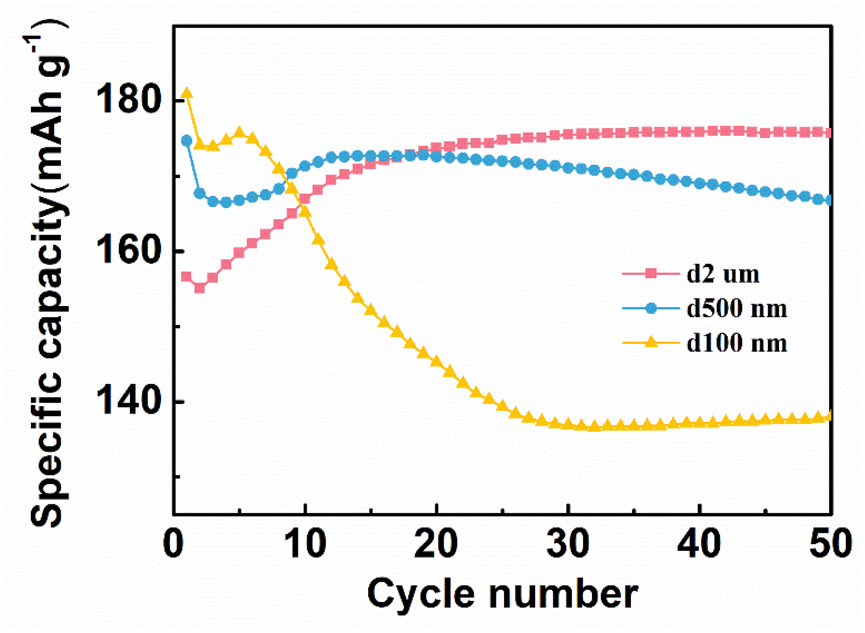
The particle size of the Ag powder has a great influence on the specific capacity and cyclic reversibility. Therefore, the specific capacity of three C/Ag/AgCl tDCS electrodes with different sizes of Ag powders as electrode active materials was also investigated. As shown in Figure 5, the CNT/Ag/AgCl–0.1 μm has the highest specific capacity (181 mAh g−1) at the first cycle of charging, probably because of the smaller size of Ag powders, the better contact with electrolytes and more accessible active sites. However, its specific capacity degrades rapidly, and decreases to 138 mAh g−1 after 50 cycles. The CNT/Ag/AgCl–0.5 μm has a little lower specific capacity (175 mAh g−1) at the first cycle. However, its specific capacity decreases as the number of cycles increases and drops down to 167 mAh g−1 after 50 cycles. In contrast, the specific capacity of the CNT/Ag/AgCl–2.0 μm dramatically increases with the increase in the number of cycles, and achieves plateau (176 mAh g−1) at 20 cycles. The active substances in the CNT/Ag/AgCl–2.0 μm are hierarchical nano- and micro-size Ag flakes. Therefore, fewer active sites present in the commercial Ag powders result in lower specific capacity in the initial stage. As the number of cycles increases, the large Ag particles are gradually pulverized into small sizes to achieve electrode activation. For durable HD-tDCS, the high and stable specific capacity is very essential. Therefore, the commercial Ag powders were chosen as the active substance.
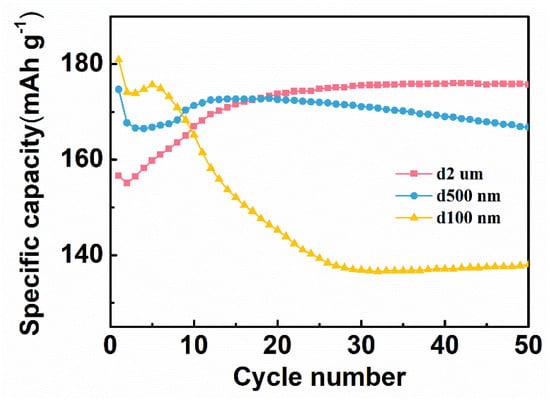
Figure 5.
Specific capacity of three C/Ag/AgCl electrodes with different sizes of Ag powders.
3.2.3. Optimization of C:Ag:PTFE Ratio
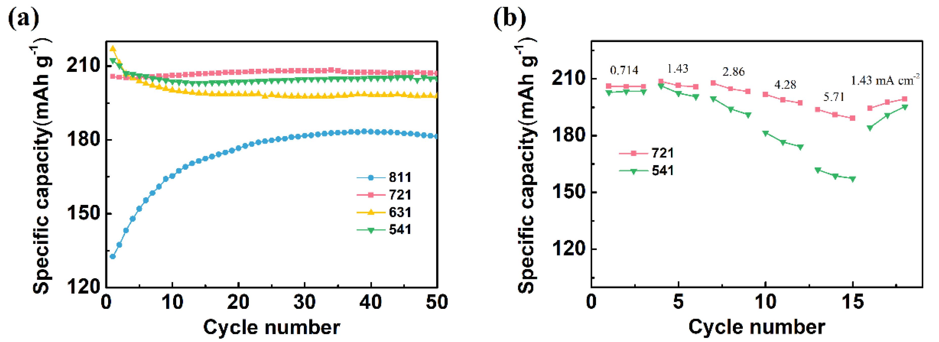
The electrochemical performance of the CNT/Ag/AgCl electrode heavily depends upon the component mass ratio. Therefore, the effect of component mass ratio on the specific capacity and cycling performance was also investigated. Herein, the CNT/Ag/AgCl electrodes with the Ag:CNT:PTFE ratio of 8:1:1, 7:2:1, 6:3:1, and 5:4:1 were nominated as the CNT/Ag/AgCl-811, CNT/Ag/AgCl-721, CNT/Ag/AgCl-631, and CNT/Ag/AgCl-541, respectively. At the first cycle, the charging specific capacity of the CNT/Ag/AgCl electrodes tends to increase as the CNT ratio increases (Figure 6a). In addition, the charging specific capacity of CNT/Ag/AgCl-811 at the first cycle is much lower than the other three electrodes (above 200 mAh g−1). More CNTs in tDCS electrodes can form compact three-dimensional interconnected conductive networks, which make silver powder disperse uniformly, and thus effectively improve the contact area between active substance and electrolyte. However, excessive CNTs in tDCS electrode will decrease the total capacity, probably due to the negligible contribution of CNTs to the reversible capacity.
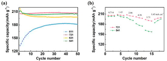
Figure 6.
(a) Specific capacity of the CNT/Ag/AgCl electrodes fabricated with various CNT:Ag:PTFE mass ratios; (b) rate performance of the CNT/Ag/AgCl-721 and the CNT/Ag/AgCl-541 electrodes (n = 3).
The specific capacity of the CNT/Ag/AgCl-721 and the CNT/Ag/AgCl-541 electrodes is very close at all cycles. For further optimization, the rate performance of these two tDCS electrodes were also investigated (Figure 6b). When charging at 0.714 mA cm−1, the specific capacity of these two tDCS electrodes almost resemble each other (~206 mAh g−1). However, the specific capacity of the CNT/Ag/AgCl-541 electrode dramatically decreases as the current density increases gradually. The CNT/Ag/AgCl-721 electrode still retains a stable specific capacity (191 mAh g−1) and even current density up to 5.71 mA cm−2. In addition, upon its return to 1.43 mA cm−2, its specific capacity recovers to the initial value (206 mAh g−1). Therefore, the optimal CNT:Ag:PTFE ratio was recommended as 7:2:1.
3.2.4. Optimization of Saline Concentration
Cl− is involved in the electrochemical reaction during HD-tDCS, so the saline concentration directly affects the specific capacity of the CNT/Ag/AgCl-721 electrode. The influence of saline concentration on the specific capacity was also explored. As shown in Figure 7, the CNT/Ag/AgCl-721 electrode in 3.0 wt.% saline outperforms the one in 0.9% and 6.0% saline in terms of both the charging specific capacity at the first cycle and specific capacity retention. The specific capacity of the CNT/Ag/AgCl-721 electrode in 0.9% saline is very close to the one in 3.0% at the first cycle. However, the specific capacity of the CNT/Ag/AgCl-721 electrode degrades gradually as the number of cycles increases to 10, probably because a low concentration of saline results in slow electrochemical kinetics on the electrode surface. In 6.0% saline, the specific capacity at the first cycle is relatively low. Then, the specific capacity suddenly increases and reaches the maximum values when the number of cycles increases to 10, mainly due to the electrode activation process. Afterwards, the specific capacity declines gradually, which may be because the high concentration of saline accelerates the electrochemical reaction, thereby yielding a dense and thick AgCl film on the electrode surface and thus leading to a capacity attenuation. Therefore, 3.0 wt.% saline was selected as the electrolyte in the following measurements.
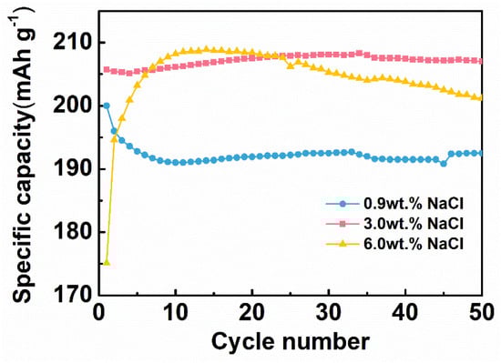
Figure 7.
Specific capacity of the CNT/Ag/AgCl-721 electrodes in 0.9 wt.%, 3.0 wt.% 6.0 wt.% at different cycles (n = 3).
Cl− is involved in the electrochemical reaction during HD-tDCS, so the saline concentration directly affects the specific capacity of the CNT/Ag/AgCl-721 electrode. The influence of saline concentration on the specific capacity was also explored. As shown in Figure 7, the CNT/Ag/AgCl-721 electrode in 3.0 wt.% saline outperforms the one in 0.9% and 6.0% saline in terms of both the charging specific capacity at the first cycle and specific capacity retention. The specific capacity of the CNT/Ag/AgCl-721 electrode in 0.9% saline is very close to the one in 3.0% at the first cycle. However, the specific capacity of the CNT/Ag/AgCl-721 electrode degrades gradually as the number of cycles increases to 10, probably because a low concentration of saline results in slow electrochemical kinetics on the electrode surface. In 6.0% saline, the specific capacity at the first cycle is relatively low. Then, the specific capacity suddenly increases and reaches the maximum values when the number of cycles increases to 10, mainly due to the electrode activation process. Afterwards, the specific capacity declines gradually, which may be because the high concentration of saline accelerates the electrochemical reaction, thereby yielding a dense and thick AgCl film on the electrode surface and thus leading to a capacity attenuation. Therefore, 3.0 wt.% saline was selected as the electrolyte in the following measurements.
3.2.5. Optimization of Active Substance Loading
In general, the increase in the active substance loading (the active substance mass per unit area) leads to the decrease in the specific capacity. As the active substance loading increases, the electrode becomes thicker, which hinders the electrolyte penetration and ion migration, resulting in the decrease in the electrode capacity. For electrical stimulation, a higher total capacity of the tDCS electrode ensures a longer service life at the constant current mode. When increasing the active substance loading, the specific capacity can remain unchanged, and thus the effective stimulation time can be prolonged. Therefore, it is well worth optimizing the active substance loading. As plotted in Figure 8, the specific capacity of the CNT/Ag/AgCl-721 electrode is almost unchanged with the active substance loading ranging from 10 to 80 mg cm−2. Therefore, the service life of the CNT/Ag/AgCl-721 electrode can be extended by increasing the active substance loading in this range.
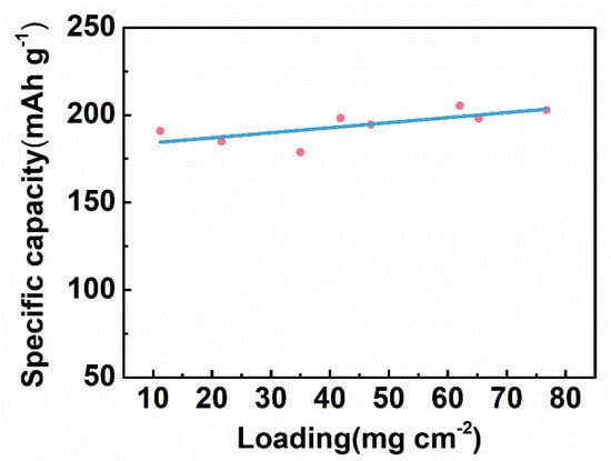
Figure 8.
Specific capacity of the CNT/Ag/AgCl-721 electrodes with various active substance loading.
3.3. Constant Current Anodic Polarization
In general, tDCS electrodes used as anode and cathode alternately can prolong their service life effectively. However, tDCS electrodes are often used randomly as anode and cathode in clinical practice. Therefore, an electrode may be continuously subjected to anodal or cathodal direct current stimulation, which leads to over-oxidation and over-reduction. After injecting anodal current stimulation continuously, the impedance of sintered Ag/AgCl electrodes increases significantly, which is due to the formation of excessive non-conductive Ag/AgCl on the electrode surface by over-oxidation. The required output voltage raises greatly accordingly. Once the required output voltage exceeds the rated output voltage of tDCS stimulators, the anodal current cannot be effectively injected into human skin [46]. Therefore, the constant current anodal polarization of the CNT/Ag/AgCl electrode was also investigated.
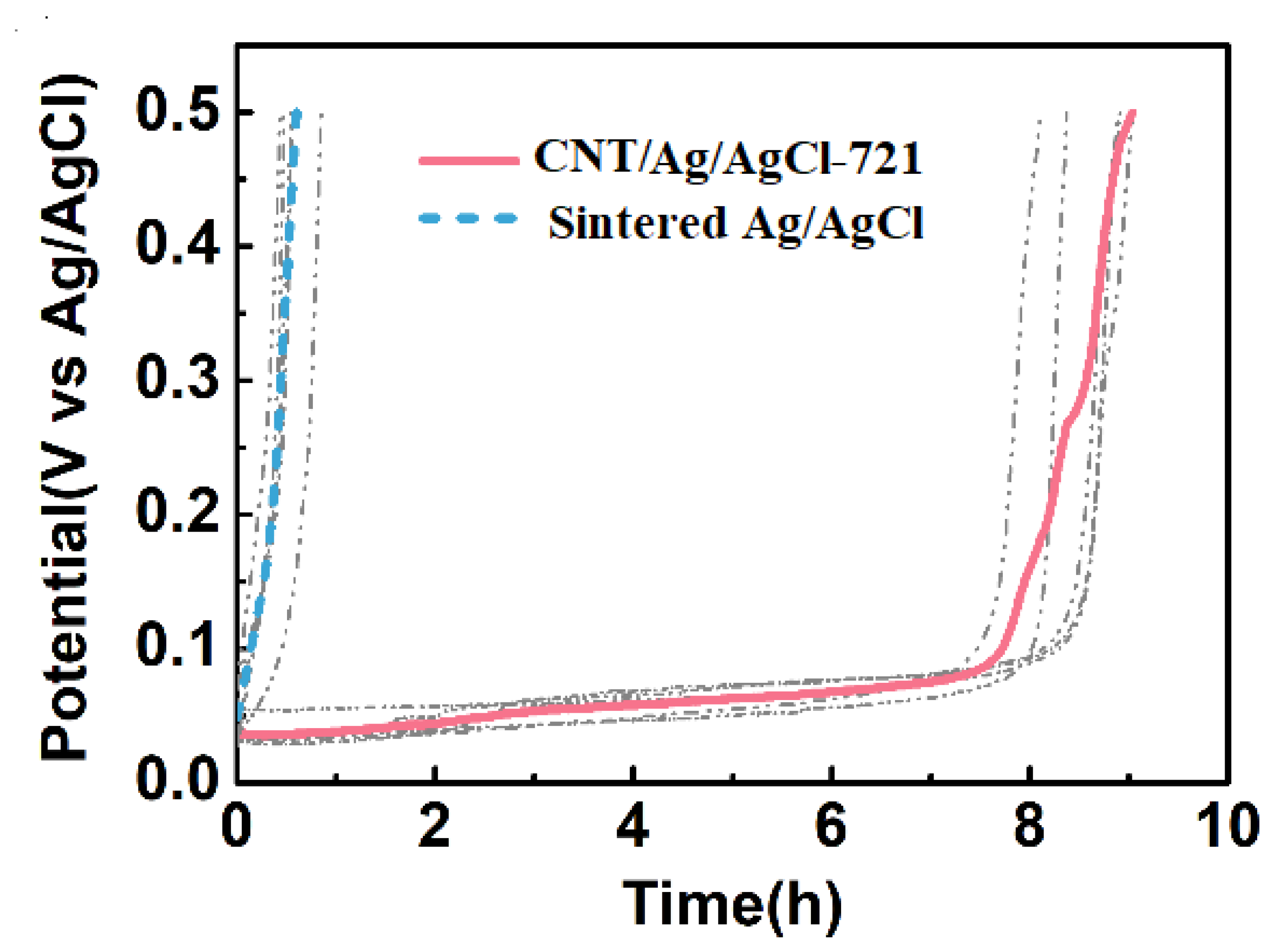
The current density is often set as 1.4 mA cm−2 (the current is 2 mA) for most HD-tDCS studies [52,53,54]. Therefore, the constant current anodal polarization tests were performed at 1.43 mA cm−2, and the plots of electrode potential versus time were also recorded during the first cycle of charging (Figure 9). The time when the electrode potential reaches the cut-off voltage (0.5 V) is regarded as the service life of the electrode. At the first cycle, the specific capacity of the CNT/Ag/AgCl-721 electrode (192.3 mAh g−1) is much higher than that of the sintered Ag/AgCl electrode (4.156 mAh g−1). After introducing CNT into Ag/AgCl, the service life of the tDCS electrode extends from 0.58 to 8.5 h. The theoretical specific capacity of Ag is 248 mAh g−1, so the utilization factors of the electrode active substance in the CNT/Ag/AgCl-721 electrode and the sintered Ag/AgCl electrode are estimated as 77.54% and 1.676%, respectively. Owing to its high utilization factor of the electrode active substance, the cost of the electrode also reduces significantly.

Figure 9.
During the first cycle of charging, the electrode potential variation of the CNT/Ag/AgCl and the sintered Ag/AgCl electrodes with time.
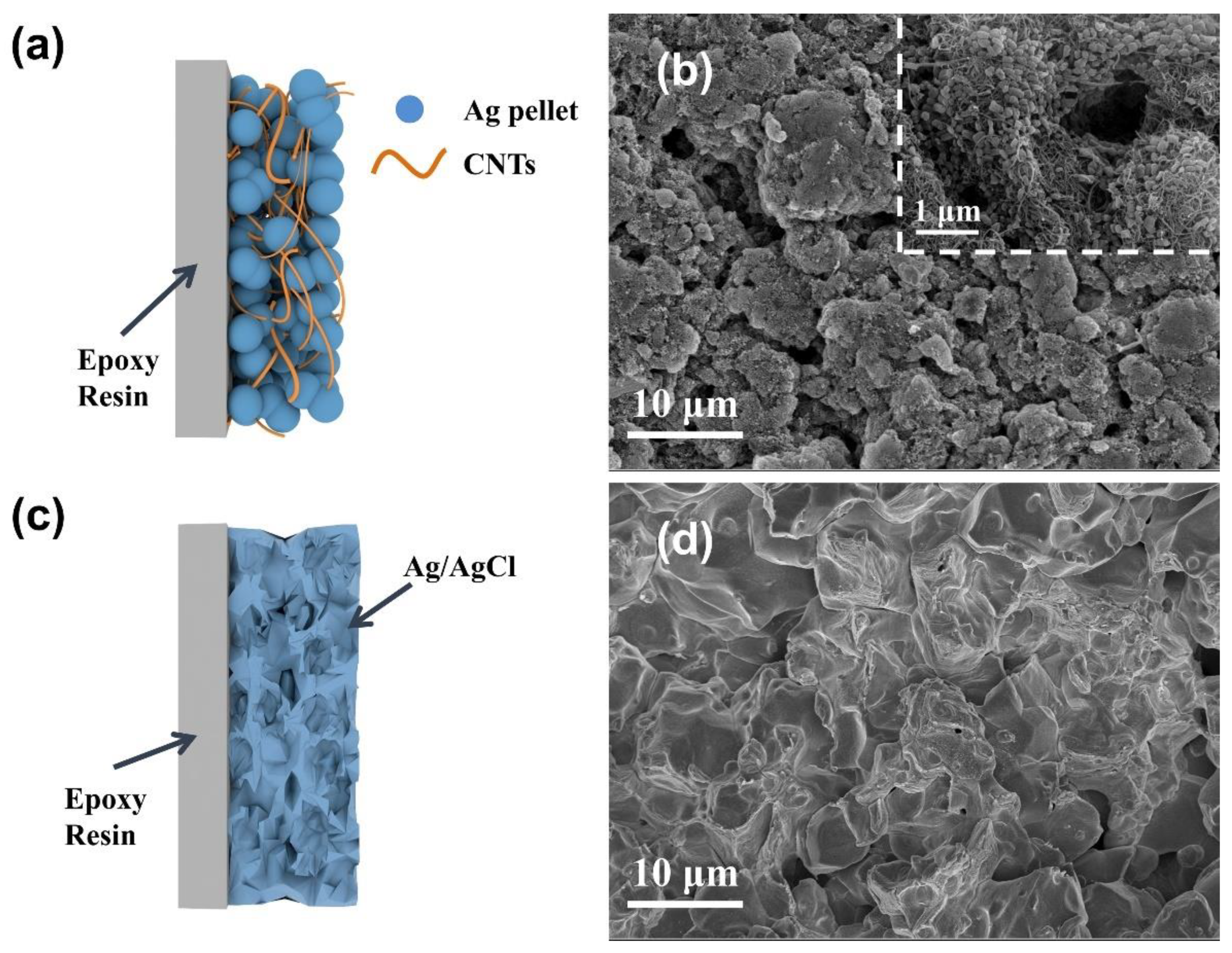
The much higher specific capacity and longer service life can be attributed to the formation of the three-dimensional interpenetrating conductive network with CNT doping (Figure 10a,b), which promotes electron and ion transport and increases the contact of active sites with the electrolyte. The sintered Ag/AgCl electrodes displays a microporous structure due to the sintering at high temperature (Figure 10c,d).
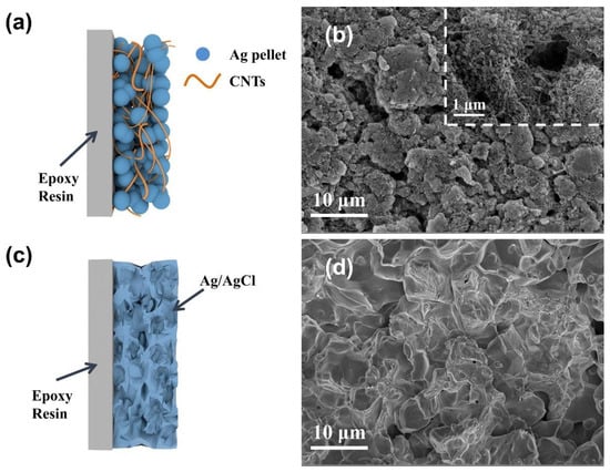
Figure 10.
Illustrative diagram of the (a) CNT/Ag/AgCl-721 and (b) sintered Ag/AgCl electrodes; SEM images of the (c) CNT/Ag/AgCl-721 and (d) sintered Ag/AgCl electrodes.
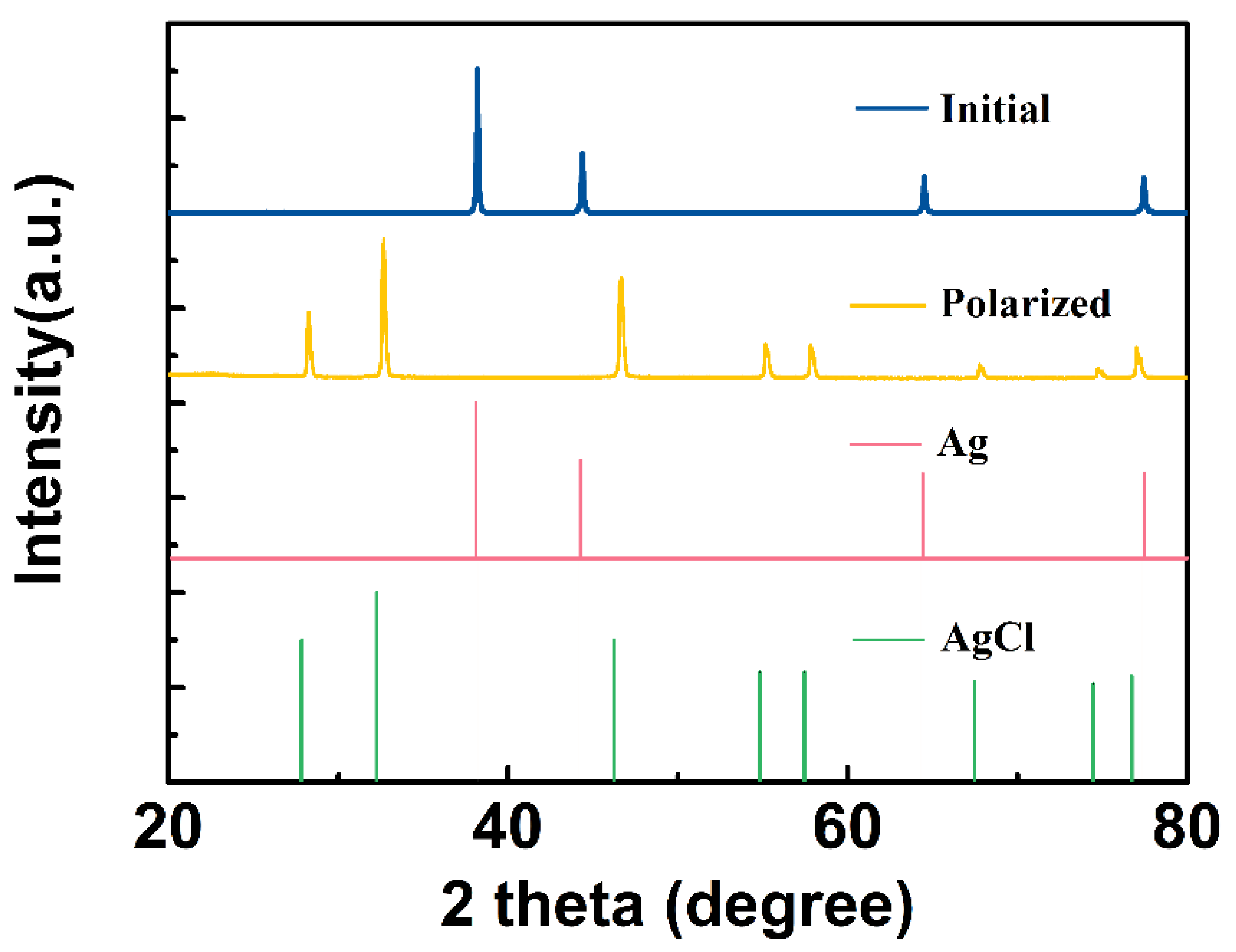
During constant current anodal polarization, the chemical composition of the CNT/Ag/AgCl electrode was studied by X-ray diffraction (XRD). The XRD patterns of the initial and polarized CNT/Ag/AgCl-721 electrodes are shown in Figure 11. The characteristic diffraction peaks of the initial CNT/Ag/AgCl electrode are highly consistent with the standard powder diffraction card of JCPDS silver file (JCPDS No. 87-0597). After anodal polarization, all the characteristic diffraction peaks are consistent with the standard diffraction peaks of AgCl (JCPDS No. 31-1238), indicating the Ag was converted to AgCl.
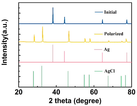
Figure 11.
XRD patterns of the initial and anodal polarized CNT/Ag/AgCl electrodes.
3.4. Simulated tDCS Measurement
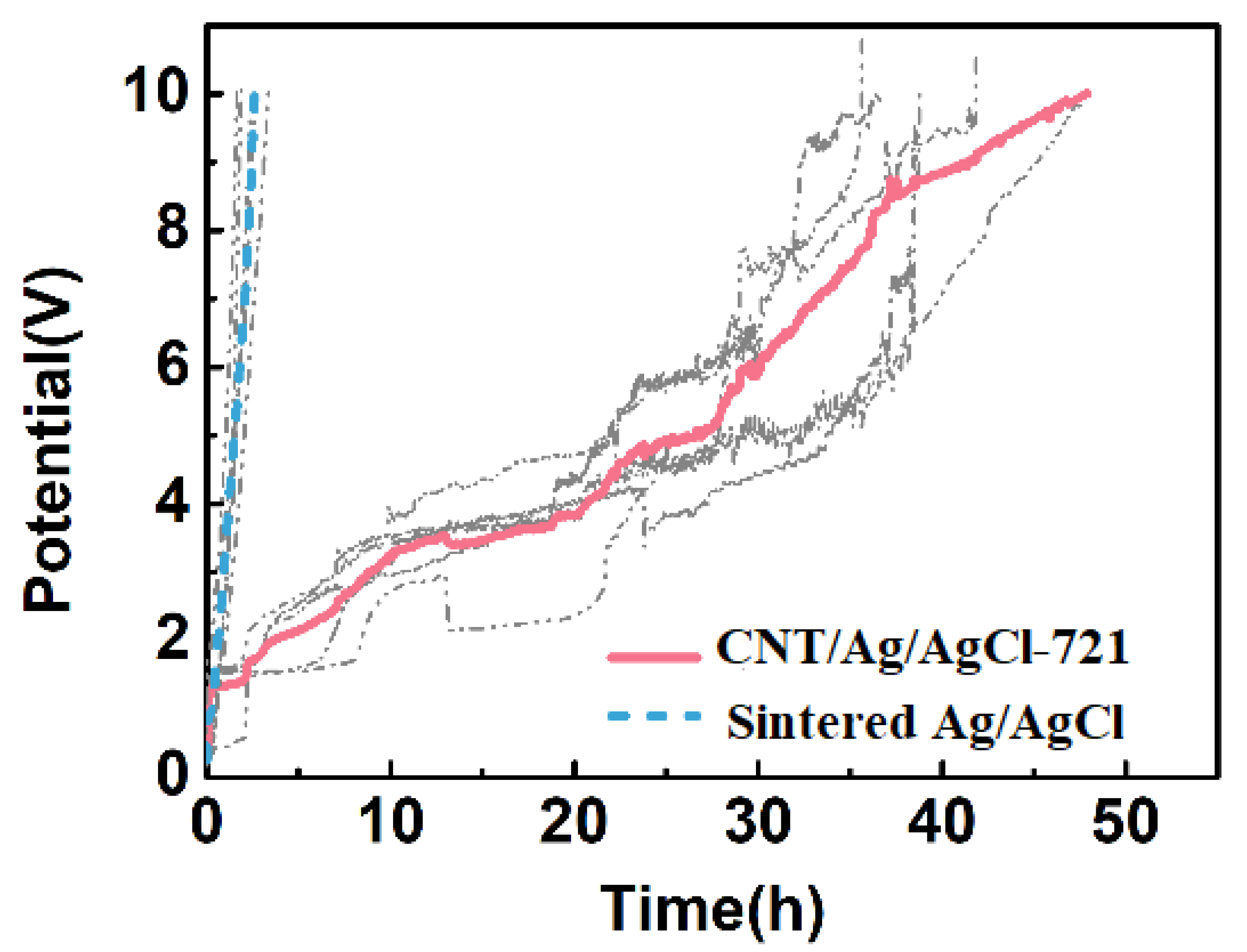
When the voltage exceeds the cut-off voltage (10 V), the electrode/skin impedance is higher than 5.0 kΩ, severely hindering the anodal or cathodal current injecting into the skin. Therefore, the voltage beyond 10 V can be used as an important index for electrode failure. The simulated tDCS measurements were performed on an agar skin phantom, and the results are shown in Figure 12. At the charging current density of 1.43 mA cm−2, the average working time of the CNT/Ag/AgCl-721 electrode is 48 h (n = 5), which is 16-fold of the one of the sintered Ag/AgCl electrodes (3 h, n = 5). With the continuous injection of an anodal current into the skin phantom, the non-conductive AgCl are gradually accumulated on the surface of the sintered Ag/AgCl electrode, which significantly increases the total impedance or voltage of the electrode and eventually leads to the failure of the electrode. When doping CNTs into the electrode, a good three-dimensional interconnected conductive network is formed, which can effectively hinder the rapid increase in impedance, and thus a higher charge is allowed to pass through the electrode. In practical applications, the tDCS electrodes are randomly used as anode and cathode. In addition, the time for a single application of tDCS is often less than 0.5 h. Therefore, the working times obtained from simulated tDCS measurements are not the actual working times during tDCS. Nevertheless, the simulated tDCS measurements demonstrate that the proposed CNT/Ag/AgCl-721 electrodes are more durable than the conventional Ag/AgCl electrodes.
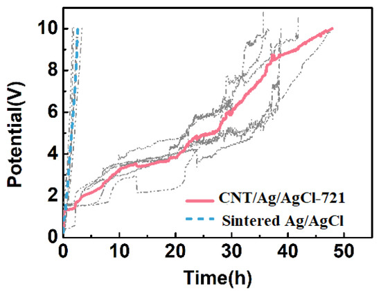
Figure 12.
Electrode potential variation of the CNT/Ag/AgCl-721 and the sintered Ag/AgCl electrodes with stimulation time.
3.5. Preliminary Evaluation of Skin Tolerance
The skin tolerance was preliminarily evaluated through a questionnaire survey. In general, previous studies have shown that skin irritation is primarily reported during the initial and end periods of tDCS, which corresponds to the stimulation current increase and decrease, respectively [48,49]. Therefore, three subjects were asked to report the skin sensations for the initial and end periods of tDCS. None of the subjects felt obvious irritation at the beginning and end of tDCS, suggesting the CNT/Ag/AgCl-721 electrode has good skin tolerance. Moreover, the skin beneath the tDCS electrodes was carefully examined after applying tDCS, and no redness or allergy was observed. These results suggest that the CNT/Ag/AgCl-721 electrode is very safe.
4. Conclusions
In this study, a novel highly durable conductive carbon/silver/silver chloride composite (C/Ag/AgCl) electrode was developed for HD-tDCS. The C/Ag/AgCl electrode was fabricated by a facile cold rolling method. The important factors affecting the specific capacity, including the conductive enhancer, the particle size of Ag powder, the C:Ag:PTFE ratio, the saline concentration, and the active substance loading were optimized systematically. The CNT/Ag/AgCl-721 electrode showed excellent specific capacity and cycling performance. At the first cycle of charging at 1.43 mA cm−2, the specific capacity of the CNT/Ag/AgCl-721 electrode (192.3 mAh g−1) is much higher than that of the sintered Ag/AgCl electrode (4.156 mAh g−1). The service life of the CNT/Ag/AgCl electrode extended from 0.58 to 8.5 h. The simulated tDCS experiments demonstrated that the service life of the CNT/Ag/AgCl-721 electrodes is 16 times that of the sintered Ag/AgCl electrodes. The much longer service life of the CNT/Ag/AgCl-721 electrodes can be attributed to the formation of the three-dimensional interpenetrating conductive network with CNT doping, which can maintain good conductivity and cycling performance even if excessive non-conductive AgCl is accumulated on the surface by long-term anodal stimulation. The preliminary evaluation of skin tolerance indicated that the proposed CNT/Ag/AgCl electrode is very safe. In summary, the proposed CNT/Ag/AgCl electrodes are very suitable for HD-tDCS, especially for daily life scenarios.
Author Contributions
Conceptualization, L.L., G.L., Y.C. and Y.Y.D.; data curation, L.L.; formal analysis, L.L. and G.L.; funding acquisition, Y.C. and Y.Y.D.; investigation, L.L.; methodology, L.L.; project administration, Y.C. and Y.Y.D.; validation, L.L.; writing—original draft, G.L.; writing—review and editing, G.L., Y.C. and Y.Y.D. All authors have read and agreed to the published version of the manuscript.
Funding
This work was financially supported by the Science and Technology Planning Project of Zhuzhou (2020015), the National Natural Science Foundation of China (No. 61703152), and the Natural Science Foundation of Hunan Province (No. 2018JJ3134).
Institutional Review Board Statement
The study was conducted according to the guidelines of the Declaration of Helsinki, and approved by the Institutional Review Board (or Ethics Committee) of Wuhan University.
Informed Consent Statement
Informed consent was obtained from all subjects involved in the study.
Data Availability Statement
All data are contained within the article.
Conflicts of Interest
The authors declare no conflict of interest. The funders had no role in the design of the study; in the collection, analyses, or interpretation of data; in the writing of the manuscript, or in the decision to publish the results.
References
- Liebetanz, D.; Nitsche, M.A.; Tergau, F.; Paulus, W. Pharmacological approach to the mechanisms of transcranial DC-stimulation-induced after-effects of human motor cortex excitability. Brain 2002, 125, 2238–2247. [Google Scholar] [CrossRef] [PubMed] [Green Version]
- Nitsche, M.A.; Liebetanz, D.; Tergau, F.; Paulus, W. Modulation of cortical excitability by transcranial direct current stimulation. Nervenarzt 2002, 73, 332–335. [Google Scholar] [CrossRef]
- Zhao, H.; Qiao, L.; Fan, D.; Zhang, S.; Turel, O.; Li, Y.; Li, J.; Xue, G.; Chen, A.; He, Q. Modulation of brain activity with noninvasive transcranial direct current stimulation (tDCS): Clinical applications and safety concerns. Front. Psychol. 2017, 8, 00685. [Google Scholar] [CrossRef]
- Kiernan, M.C.; Bostock, H. Effects of membrane polarization and ischaemia on the excitability properties of human motor axons. Brain 2000, 123, 2542–2551. [Google Scholar] [CrossRef] [PubMed] [Green Version]
- VanHaerents, S.; Chang, B.S.; Rotenberg, A.; Pascual-Leone, A.; Shafi, M.M. Noninvasive Brain Stimulation in Epilepsy. J. Clin. Neurophysiol. 2020, 37, 118–130. [Google Scholar] [CrossRef] [PubMed]
- Auvichayapat, N.; Rotenberg, A.; Gersner, R.; Ngodklang, S.; Tiamkao, S.; Tassaneeyakul, W.; Auvichayapat, P. Transcranial Direct Current Stimulation for Treatment of Refractory Childhood Focal Epilepsy. Brain Stimul. 2013, 6, 696–700. [Google Scholar] [CrossRef] [PubMed]
- Han, C.-L.; Hu, W.; Stead, M.; Zhang, T.; Zhang, J.-G.; Worrell, G.A.; Meng, F.-G. Electrical stimulation of hippocampus for the treatment of refractory temporal lobe epilepsy. Brain Res. Bull. 2014, 109, 13–21. [Google Scholar] [CrossRef]
- Morrell, M.J. Responsive cortical stimulation for the treatment of medically intractable partial epilepsy. Neurology 2011, 77, 1295–1304. [Google Scholar] [CrossRef]
- Moffa, A.H.; Martin, D.; Alonzo, A.; Bennabi, D.; Blumberger, D.M.; Benseñor, I.M.; Daskalakis, Z.; Fregni, F.; Haffen, E.; Lisanby, S.H.; et al. Efficacy and acceptability of transcranial direct current stimulation (tDCS) for major depressive disorder: An individual patient data meta-analysis. Prog. NeuroPsychopharmacol. Biol. Psychiatry 2020, 99, 109836. [Google Scholar] [CrossRef]
- Bares, M.; Brunovsky, M.; Stopkova, P.; Hejzlar, M.; Novak, T. Transcranial Direct-Current Stimulation (tDCS) Versus Venlafaxine ER in The Treatment of Depression: A Randomized, Double-Blind, Single-Center Study with Open-Label, Follow-Up. Neuropsychiatr. Dis. Treat. 2019, 15, 3003–3014. [Google Scholar] [CrossRef] [Green Version]
- Orrù, G.; Conversano, C.; Hitchcott, P.K.; Gemignani, A. Motor stroke recovery after tDCS: A systematic review. Rev. Neurosci. 2020, 31, 201–218. [Google Scholar] [CrossRef] [PubMed]
- Shibata, T.; Urata, A.; Kawahara, K.; Furuya, K.; Ishikuro, K.; Hattori, N.; Kuroda, S. Therapeutic Effects of Diagonal-Transcranial Direct Current Stimulation on Functional Recovery in Acute Stroke: A Pilot Study. J. Stroke Cerebrovasc. Dis. 2020, 29, 105107. [Google Scholar] [CrossRef]
- da Silva, R.d.F.; Batistuzzo, M.C.; Shavitt, R.G.; Miguel, E.C.; Stern, E.; Mezger, E.; Padberg, F.; D’Urso, G.; Brunoni, A.R. Transcranial direct current stimulation in obsessive-compulsive disorder: An update in electric field modeling and investigations for optimal electrode montage. Expert Rev. Neurother. 2019, 19, 1025–1035. [Google Scholar] [CrossRef]
- Horiba, M.; Ueki, Y.; Nojima, I.; Shimizu, Y.; Sahashi, K.; Itamoto, S.; Suzuki, A.; Yamada, G.; Matsukawa, N.; Wada, I. Impaired Motor Skill Acquisition Using Mirror Visual Feedback Improved by Transcranial Direct Current Stimulation (tDCS) in Patients with Parkinson’s Disease. Front. Neurosci. 2019, 13, 602. [Google Scholar] [CrossRef]
- Bystad, M.; Rasmussen, I.D.; Grønli, O.; Aslaksen, P. Can 8 months of daily tDCS application slow the cognitive decline in Alzheimer’s disease? A case study. Neurocase 2017, 23, 146–148. [Google Scholar] [CrossRef]
- Castillo-Saavedra, L.; Gebodh, N.; Bikson, M.; Diaz-Cruz, C.; Brandao, R.; Coutinho, L.; Truong, D.; Datta, A.; Shani-Hershkovich, R.; Weiss, M.; et al. Clinically Effective Treatment of Fibromyalgia Pain with High-Definition Transcranial Direct Current Stimulation: Phase II Open-Label Dose Optimization. J. Pain 2016, 17, 14–26. [Google Scholar] [CrossRef] [PubMed] [Green Version]
- DaSilva, A.F.; Truong, D.Q.; DosSantos, M.; Toback, R.L.; Datta, A.; Bikson, M. State-of-art neuroanatomical target analysis of high-definition and conventional tDCS montages used for migraine and pain control. Front. Neuroanat. 2015, 9, 89. [Google Scholar] [CrossRef] [Green Version]
- Khedr, E.M.; Gamal, N.F.E.; El-Fetoh, N.A.; Khalifa, H.; Ahmed, E.M.; Ali, A.M.; Noaman, M.; El-Baki, A.A.; Karim, A.A. A double-blind randomized clinical trial on the efficacy of cortical direct current stimulation for the treatment of Alzheimer’s disease. Front. Aging Neurosci. 2014, 6, 275. [Google Scholar] [CrossRef] [PubMed]
- Sheltraw, D.J.; Inglis, B.; Labruna, L.; Ivry, R. Comparing the electric fields of transcranial electric and magnetic perturbation. J. Neural Eng. 2021, 18, 046067. [Google Scholar] [CrossRef]
- Antal, A.; Alekseichuk, I.; Bikson, M.; Brockmöller, J.; Brunoni, A.R.; Chen, R.; Cohen, L.; Dowthwaite, G.; Ellrich, J.; Flöel, A.; et al. Low intensity transcranial electric stimulation: Safety, ethical, legal regulatory and application guidelines. Clin. Neurophysiol. 2017, 128, 1774–1809. [Google Scholar] [CrossRef] [Green Version]
- Bikson, M.; Grossman, P.; Thomas, C.; Zannou, A.L.; Jiang, J.; Adnan, T.; Mourdoukoutas, A.P.; Kronberg, G.; Truong, D.; Boggio, P.; et al. Safety of Transcranial Direct Current Stimulation: Evidence Based Update 2016. Brain Stimul. 2016, 9, 641–661. [Google Scholar] [CrossRef] [Green Version]
- Aparício, L.V.; Guarienti, F.; Razza, L.B.; Carvalho, A.F.; Fregni, F.; Brunoni, A.R. A Systematic Review on the Acceptability and Tolerability of Transcranial Direct Current Stimulation Treatment in Neuropsychiatry Trials. Brain Stimul. 2016, 9, 671–681. [Google Scholar] [CrossRef]
- Woods, A.; Antal, A.; Bikson, M.; Boggio, P.; Brunoni, A.R.; Celnik, P.; Cohen, L.; Fregni, F.; Herrmann, C.; Kappenman, E.; et al. A technical guide to tDCS, and related non-invasive brain stimulation tools. Clin. Neurophysiol. 2016, 127, 1031–1048. [Google Scholar] [CrossRef] [Green Version]
- Charvet, L.E.; Shaw, M.T.; Bikson, M.; Woods, A.J.; Knotkova, H. Supervised transcranial direct current stimulation (tDCS) at home: A guide for clinical research and practice. Brain Stimul. 2020, 13, 686–693. [Google Scholar] [CrossRef] [Green Version]
- Shaw, M.; Pilloni, G.; Charvet, L. Delivering Transcranial Direct Current Stimulation Away from Clinic: Remotely Supervised tDCS. Mil. Med. 2020, 185, 319–325. [Google Scholar] [CrossRef] [PubMed] [Green Version]
- Pilloni, G.; Shaw, M.; Feinberg, C.; Clayton, A.; Palmeri, M.; Datta, A.; Charvet, L.E. Long term at-home treatment with transcranial direct current stimulation (tDCS) improves symptoms of cerebellar ataxia: A case report. J. NeuroEng. Rehabil. 2019, 16, 1–8. [Google Scholar] [CrossRef] [PubMed] [Green Version]
- Clayton, A.M.; Howard, J.; Dobbs, B.; Shaw, M.T.; Charvet, L.E. Remotely supervised transcranial direct current stimulation after ECT improves mood and cognition in a patient with multiple sclerosis: A case study. J. ECT 2018, 34, e15. [Google Scholar] [CrossRef] [PubMed]
- Masina, F.; Arcara, G.; Galletti, E.; Cinque, I.; Gamberini, L.; Mapelli, D. Neurophysiological and behavioural effects of conventional and high definition tDCS. Sci. Rep. 2021, 11, 1–11. [Google Scholar] [CrossRef] [PubMed]
- DaSilva, A.F.; Volz, M.S.; Bikson, M.; Fregni, F. Electrode Positioning and Montage in Transcranial Direct Current Stimulation. J. Vis. Exp. 2011, 51, e2744. [Google Scholar] [CrossRef] [Green Version]
- Solomons, C.D.; Shanmugasundaram, V. Transcranial direct current stimulation: A review of electrode characteristics and materials. Med. Eng. Phys. 2020, 85, 63–74. [Google Scholar] [CrossRef]
- Villamar, M.F.; Volz, M.S.; Bikson, M.; Datta, A.; DaSilva, A.F.; Fregni, F. Technique and considerations in the use of 4 × 1 ring high-definition transcranial direct current stimulation (HD-tDCS). J. Vis. Exp. 2013, 77, e50309. [Google Scholar] [CrossRef]
- Merrill, D.R.; Bikson, M.; Jefferys, J.G.R. Electrical stimulation of excitable tissue: Design of efficacious and safe protocols. J. Neurosci. Methods 2005, 141, 171–198. [Google Scholar] [CrossRef]
- Pellegrini, M.; Zoghi, M.; Jaberzadeh, S. The effects of transcranial direct current stimulation on corticospinal and cortico-cortical excitability and response variability: Conventional versus high-definition montages. Neurosci. Res. 2021, 166, 12–25. [Google Scholar] [CrossRef]
- To, W.T.; Hart, J.; De Ridder, D.; Vanneste, S. Considering the influence of stimulation parameters on the effect of conventional and high-definition transcranial direct current stimulation. Expert Rev. Med. Devices 2016, 13, 391–404. [Google Scholar] [CrossRef]
- Kuo, H.-I.; Bikson, M.; Datta, A.; Minhas, P.; Paulus, W.; Kuo, M.-F.; Nitsche, M.A. Comparing Cortical Plasticity Induced by Conventional and High-Definition 4 × 1 Ring tDCS: A Neurophysiological Study. Brain Stimul. 2013, 6, 644–648. [Google Scholar] [CrossRef] [PubMed]
- Edwards, D.; Cortes, M.; Datta, A.; Minhas, P.; Wassermann, E.M.; Bikson, M. Physiological and modeling evidence for focal transcranial electrical brain stimulation in humans: A basis for high-definition tDCS. NeuroImage 2013, 74, 266–275. [Google Scholar] [CrossRef] [Green Version]
- Caparelli-Daquer, E.; Zimmermann, T.J.; Mooshagian, E.; Parra, L.C.; Rice, J.K.; Datta, A.; Bikson, M.; Wassermann, E.M. A pilot study on effects of 4 × 1 High-Definition tDCS on motor cortex excitability. In Proceedings of the 2012 Annual International Conference of the IEEE Engineering in Medicine and Biology Society, San Diego, CA, USA, 28 August–1 September 2012; pp. 735–738. [Google Scholar]
- Datta, A.; Bansal, V.; Diaz, J.; Patel, J.; Reato, D.; Bikson, M. Gyri-precise head model of transcranial direct current stimulation: Improved spatial focality using a ring electrode versus conventional rectangular pad. Brain Stimul. 2009, 2, 201–207. [Google Scholar] [CrossRef] [PubMed] [Green Version]
- Villamar, M.F.; Wivatvongvana, P.; Patumanond, J.; Bikson, M.; Truong, D.Q.; Datta, A.; Fregni, F. Focal modulation of the primary motor cortex in fibromyalgia using 4 × 1-ring high-definition transcranial direct current stimulation (HD-tDCS): Immediate and delayed analgesic effects of cathodal and anodal stimulation. J. Pain 2013, 14, 371–383. [Google Scholar] [CrossRef]
- Tallgren, P.; Vanhatalo, S.; Kaila, K.; Voipio, J. Evaluation of commercially available electrodes and gels for recording of slow EEG potentials. Clin. Neurophysiol. 2005, 116, 799–806. [Google Scholar] [CrossRef] [PubMed]
- Li, G.; Wu, J.; Xia, Y.; Wu, Y.; Tian, Y.; Liu, J.; Chen, D.; He, Q. Towards emerging EEG applications: A novel printable flexible Ag/AgCl dry electrode array for robust recording EEG signals at forehead sites. J. Neural Eng. 2020, 17, 026001. [Google Scholar] [CrossRef]
- Li, G.-L.; Wu, J.-T.; Xia, Y.-H.; He, Q.-G.; Jin, H.-G. Review of semi-dry electrodes for EEG recording. J. Neural Eng. 2020, 17, 051004. [Google Scholar] [CrossRef]
- Li, G.; Wang, S.; Li, M.; Duan, Y.Y. Towards real-life EEG applications: Novel superporous hydrogel-based semi-dry EEG electrodes enabling automatically charge-discharge electrolyte. J. Neural Eng. 2021, 18, 046016. [Google Scholar] [CrossRef]
- Li, G.; Wang, S.; Duan, Y.Y. Towards conductive-gel-free electrodes: Understanding the wet electrode, semi-dry electrode and dry electrode-skin interface impedance using electrochemical impedance spectroscopy fitting. Sens Actuators B Chem. 2018, 277, 250–260. [Google Scholar] [CrossRef]
- Minhas, P.; Bansal, V.; Patel, J.; Ho, J.S.; Diaz, J.; Datta, A.; Bikson, M. Electrodes for high-definition transcutaneous DC stimulation for applications in drug delivery and electrotherapy, including tDCS. J. Neurosci. Methods 2010, 190, 188–197. [Google Scholar] [CrossRef] [PubMed] [Green Version]
- Langenbach, B.P.; Savic, B.; Baumgartner, T.; Knoch, D. Repeated anodal HD-tDCS stimulation might render silver chloride electrodes unreliable. Brain Stimul. 2020, 13, 525–526. [Google Scholar] [CrossRef]
- Hampstead, B.M.; Ehmann, M.; Rahman-Filipiak, A. Reliable use of silver chloride HD-tDCS electrodes. Brain Stimul. 2020, 13, 1005–1007. [Google Scholar] [CrossRef] [PubMed]
- Nitsche, M.A.; Liebetanz, D.; Lang, N.; Antal, A.; Tergau, F.; Paulus, W. Safety criteria for transcranial direct current stimulation (tDCS) in humans. Clin. Neurophysiol. 2003, 114, 2220–2222. [Google Scholar] [CrossRef]
- Gandiga, P.C.; Hummel, F.C.; Cohen, L.G. Transcranial DC stimulation (tDCS): A tool for double-blind sham-controlled clinical studies in brain stimulation. Clin. Neurophysiol. 2006, 117, 845–850. [Google Scholar] [CrossRef]
- Chhatbar, P.Y.; Chen, R.; Deardorff, R.; Dellenbach, B.; Kautz, S.A.; George, M.S.; Feng, W. Safety and tolerability of transcranial direct current stimulation to stroke patients—A phase I current escalation study. Brain Stimul. 2017, 10, 553–559. [Google Scholar] [CrossRef] [PubMed] [Green Version]
- Poreisz, C.; Boros, K.; Antal, A.; Paulus, W. Safety aspects of transcranial direct current stimulation concerning healthy subjects and patients. Brain Res. Bull. 2007, 72, 208–214. [Google Scholar] [CrossRef]
- Maldonado, T.; Bernard, J.A. The polarity-specific nature of single-session high-definition transcranial direct current stimulation to the cerebellum and prefrontal cortex on motor and non-motor task performance. Cerebellum 2021, 2021, 1–15. [Google Scholar] [CrossRef]
- Jog, M.S.; Kim, E.; Anderson, C.; Kubicki, A.; Kayathi, R.; Jann, K.; Yan, L.; Leaver, A.; Hellemann, G.; Iacoboni, M.; et al. In-vivo imaging of targeting and modulation of depression-relevant circuitry by transcranial direct current stimulation: A randomized clinical trial. Transl. Psychiatry 2021, 11, 138. [Google Scholar] [CrossRef] [PubMed]
- Sasia, B.; Cacciamani, L. High-definition transcranial direct current stimulation of the lateral occipital cortex influences figure-ground perception. Neuropsychologia 2021, 155, 107792. [Google Scholar] [CrossRef] [PubMed]


Publisher’s Note: MDPI stays neutral with regard to jurisdictional claims in published maps and institutional affiliations. |
© 2021 by the authors. Licensee MDPI, Basel, Switzerland. This article is an open access article distributed under the terms and conditions of the Creative Commons Attribution (CC BY) license (https://creativecommons.org/licenses/by/4.0/).