
Strong Polyamide-6 Nanocomposites with Cellulose Nanofibers Mediated by Green Solvent Mixtures


Abstract
:1. Introduction
2. Materials and Methods
2.1. Materials
2.2. Methods
2.2.1. Preparation of PA6-CNF Nanocomposite Films
2.2.2. Tensile Tests
2.2.3. Scanning Electron Microscopy (SEM)
2.2.4. Fourier Transform Infrared Spectroscopy (FTIR)
2.2.5. Thermogravimetric Analysis (TGA)
2.2.6. Differential Scanning Calorimetry (DSC)
2.2.7. Dynamic Mechanical Analysis (DMA)
3. Results and Discussions
3.1. Morphology
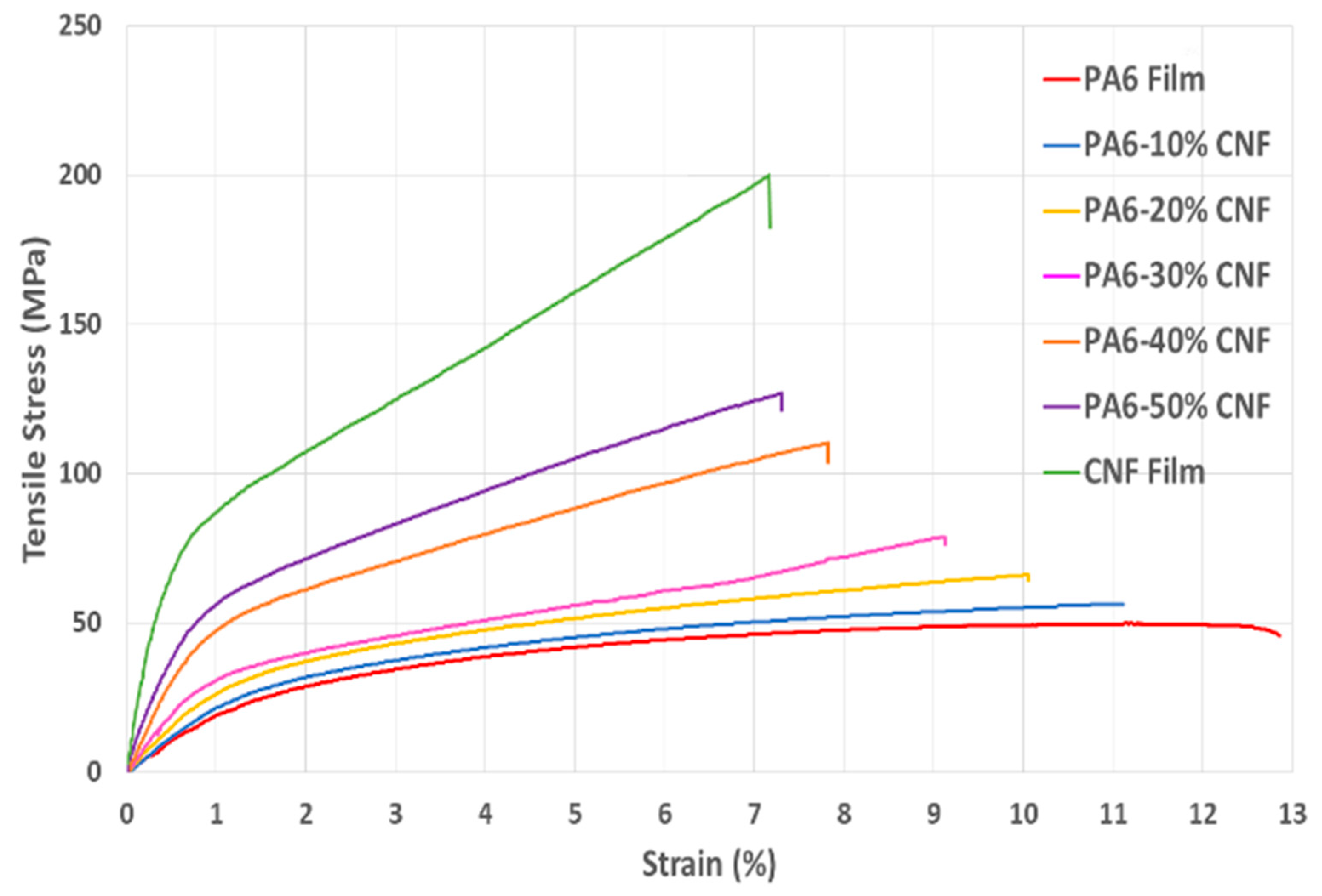
3.2. Tensile Tests
3.3. SEM Analysis
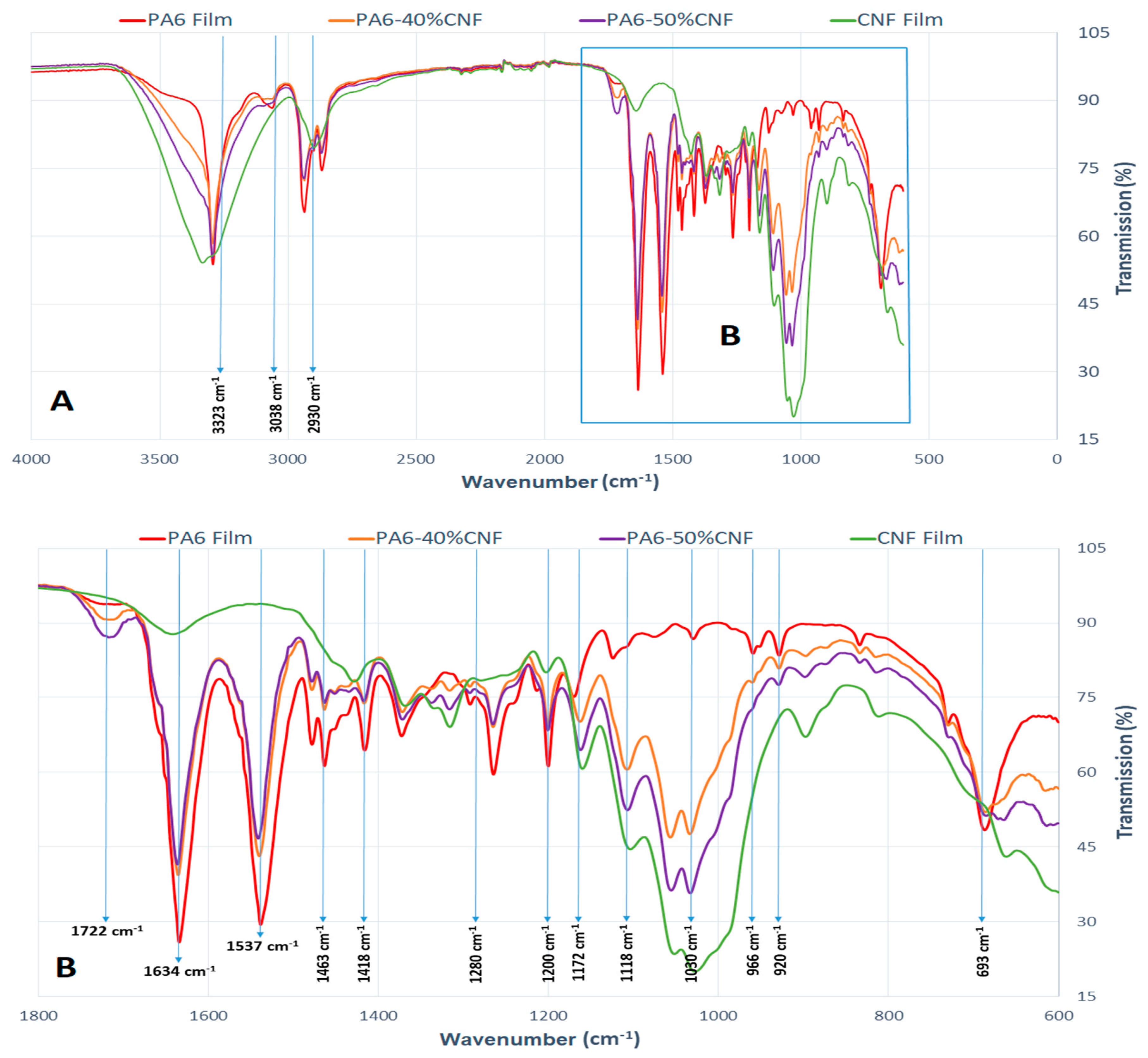
3.4. FTIR Analysis
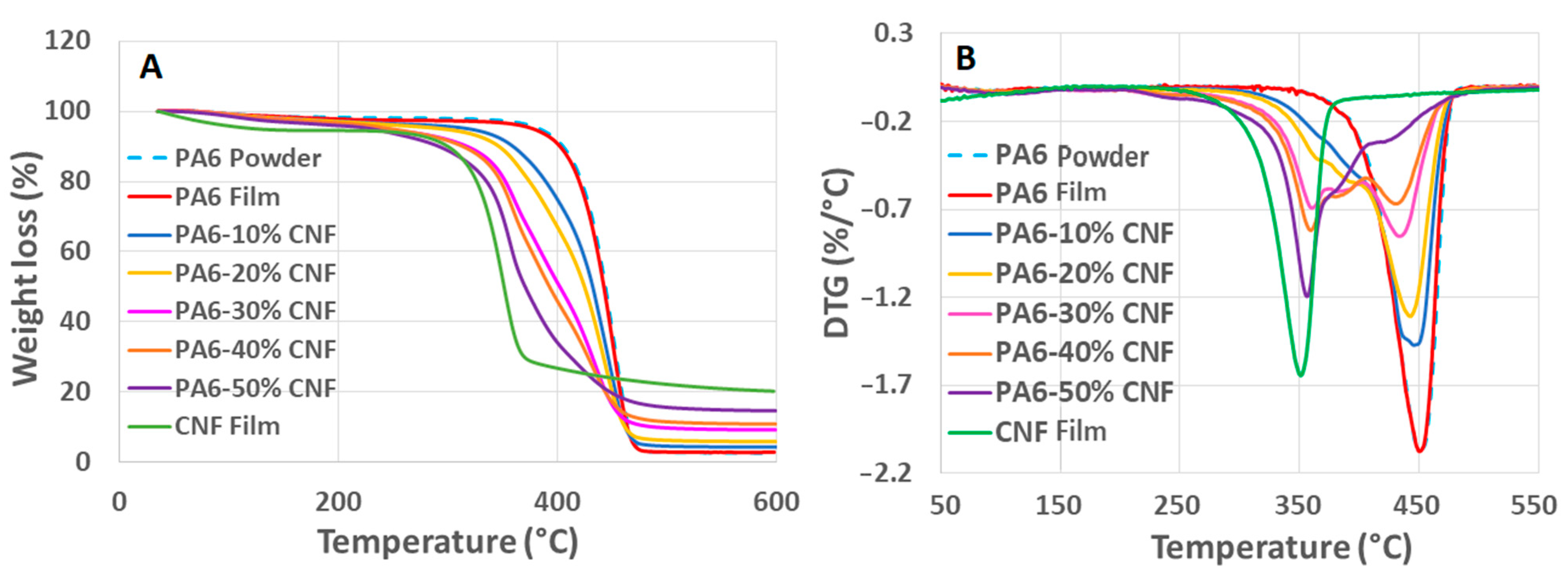
3.5. TGA Analysis
3.6. DSC Analysis
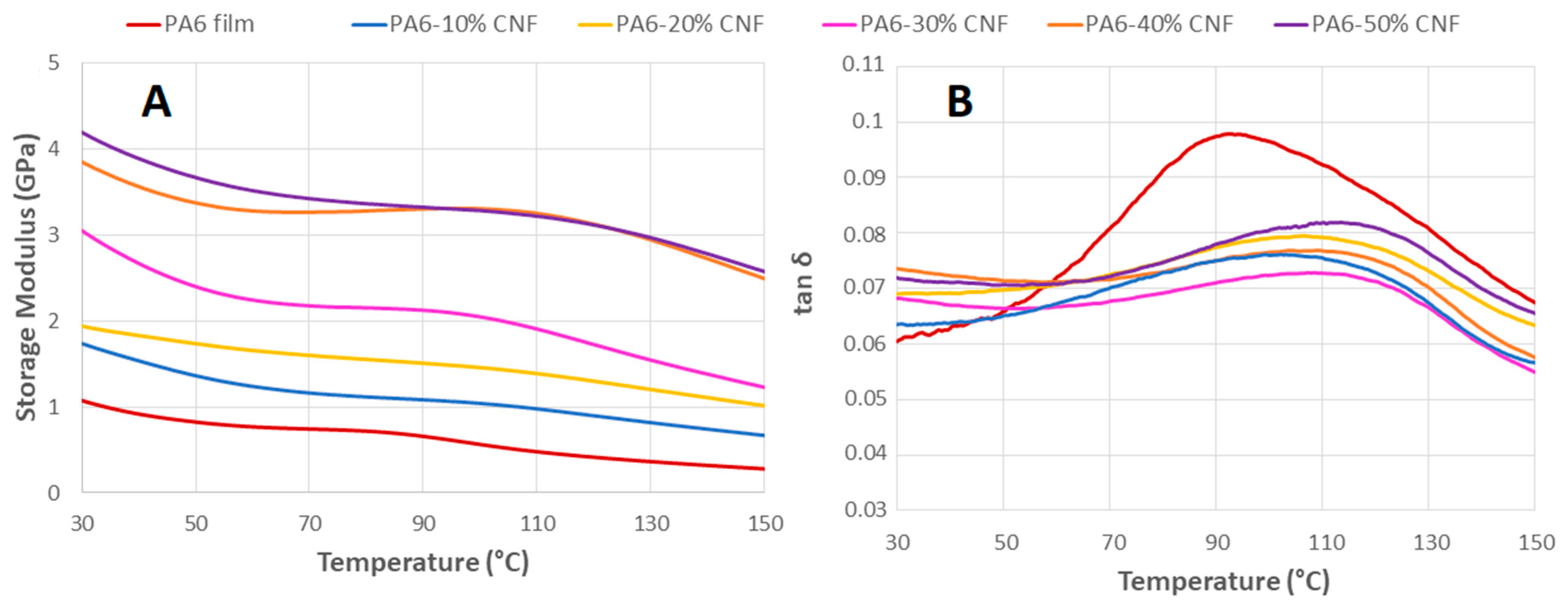
3.7. DMA Tests
4. Conclusions
Author Contributions
Funding
Institutional Review Board Statement
Informed Consent Statement
Data Availability Statement
Acknowledgments
Conflicts of Interest
References
- Lee, K.Y.; Aitomäki, Y.; Berglund, L.A.; Oksman, K.; Bismarck, A. On the use of nanocellulose as reinforcement in polymer matrix composites. Compos. Sci. Technol. 2014, 105, 15–27. [Google Scholar] [CrossRef] [Green Version]
- Kargarzadeh, H.; Huang, J.; Lin, N.; Ahmad, I.; Mariano, M.; Dufresne, A.; Thomas, S.; Gałęski, A. Recent developments in nanocellulose-based biodegradable polymers, thermoplastic polymers, and porous nanocomposites. Prog. Polym. Sci. 2018, 87, 197–227. [Google Scholar] [CrossRef]
- Eichhorn, S.J.; Dufresne, A.; Aranguren, M.; Marcovich, N.E.; Capadona, J.R.; Rowan, S.J.; Weder, C.; Thielemans, W.; Roman, M.; Renneckar, S.; et al. Review: Current International Research into Cellulose Nanofibres and Nanocomposites. J. Mater. Sci. 2010, 45, 1–33. [Google Scholar] [CrossRef] [Green Version]
- Dufresne, A. Cellulose nanomaterial reinforced polymer nanocomposites. Curr. Opin. Colloid Interface Sci. 2017, 29, 1–8. [Google Scholar] [CrossRef]
- Moon, R.J.; Schueneman, G.T.; Simonsen, J. Overview of Cellulose Nanomaterials, Their Capabilities and Applications. JOM 2016, 68, 2383–2394. [Google Scholar] [CrossRef]
- Börjesson, M.; Westman, G. Crystalline Nanocellulose—Preparation, Modification, and Properties; Börjesson, M., Westman, G., Eds.; IntechOpen: London, UK, 2015; pp. 159–191. [Google Scholar]
- de Assis, C.A.; Houtman, C.; Phillips, R.; Bilek, E.M.; Rojas, O.J.; Pal, L.; Peresin, M.S.; Jameel, H.; Gonzalez, R. Conversion economics of forest biomaterials: Risk and financial analysis of CNC manufacturing. Biofuels Bioprod. Biorefin. 2017, 11, 682–700. [Google Scholar] [CrossRef]
- Kiziltas, A.; Erbas Kiziltas, E.; Boran, S.; Gardner, D.J. Micro-and nanocellulose composites for automotive applications. In Proceedings of the SPE Automotive Composites Conference and Exhibition, Novi, MI, USA, 11–13 September 2013; pp. 11–13. [Google Scholar]
- Francisco, D.L.; Paiva, L.B.; Aldeia, W. Advances in polyamide nanocomposites: A review. Polym. Compos. 2019, 40, 851–870. [Google Scholar] [CrossRef]
- Shokoohi, S.; Arefazar, A.; Khosrokhavar, R. Silane coupling agents in polymer-based reinforced composites: A review. J. Reinf. Plast. Compos. 2008, 27, 473–485. [Google Scholar] [CrossRef]
- Alonso-Montemayor, F.J.; Tarrés, Q.; Oliver-Ortega, H.; Espinach, F.X.; Narro-Céspedes, R.I.; Castañeda-Facio, A.O.; Delgado-Aguilar, M. Enhancing the Mechanical Performance of Bleached Hemp Fibers Reinforced Polyamide 6 Composites: A Competitive Alternative to Commodity Composites. Polymers 2020, 12, 1041. [Google Scholar] [CrossRef]
- Sridhara, P.K.; Vilaseca, F. Assessment of Fiber Orientation on the Mechanical Properties of PA6/Cellulose Composite. Appl. Sci. 2020, 10, 5565. [Google Scholar] [CrossRef]
- Lo Re, G.; Sessini, V. Wet feeding approach for cellulosic materials/PCL Biocomposites. In Biomass Extrusion and Reaction Technologies: Principles to Practices and Future Potential; ACS Publications: Washington, DC, USA, 2018; pp. 209–226. ISBN 19475918. [Google Scholar]
- Dufresne, A. Cellulose nanomaterials as green nanoreinforcements for polymer nanocomposites. Philos. Trans. R. Soc. Math. Phys. Eng. Sci. 2018, 376, 20170040. [Google Scholar] [CrossRef]
- Kong, I.; Tshai, K.Y.; Hoque, M.E. Manufacturing of natural fibre-reinforced polymer composites by solvent casting method. In Manufacturing of Natural Fibre Reinforced Polymer Composites; Springer: Berlin/Heidelberg, Germany, 2015; pp. 331–349. [Google Scholar]
- Chang, H.-Y.; Shih, T.-S.; Guo, Y.L.; Tsai, C.-Y.; Hsu, P.-C. Sperm function in workers exposed to N,N-dimethylformamide in the synthetic leather industry. Fertil. Steril. 2004, 81, 1589–1594. [Google Scholar] [CrossRef]
- Nirmala, R.; Panth, H.R.; Yi, C.; Nam, K.T.; Park, S.-J.; Kim, H.Y.; Navamathavan, R. Effect of solvents on high aspect ratio polyamide-6 nanofibers via electrospinning. Macromol. Res. 2010, 18, 759–765. [Google Scholar] [CrossRef]
- Hocker, S.; Rhudy, A.K.; Ginsburg, G.; Kranbuehl, D.E. Polyamide hydrolysis accelerated by small weak organic acids. Polymer 2014, 55, 5057–5064. [Google Scholar] [CrossRef]
- Sucharitpong, T.; Lam, N.T.; Sukyai, P. Production of Nylon-6/Cellulose Nanocrystal Composite Films Using Solvent Dissolution. Sugar Tech 2020, 22, 328–339. [Google Scholar] [CrossRef]
- Henriksson, M.; Henriksson, G.; Berglund, L.A.; Lindström, T. An environmentally friendly method for enzyme-assisted preparation of microfibrillated cellulose (MFC) nanofibers. Eur. Polym. J. 2007, 43, 3434–3441. [Google Scholar] [CrossRef]
- Tarrés, Q.; Boufi, S.; Mutjé, P.; Delgado-Aguilar, M. Enzymatically hydrolyzed and TEMPO-oxidized cellulose nanofibers for the production of nanopapers: Morphological, optical, thermal and mechanical properties. Cellulose 2017, 24, 3943–3954. [Google Scholar] [CrossRef]
- Wang, J.; Liu, X.; Jin, T.; He, H.; Liu, L. Preparation of nanocellulose and its potential in reinforced composites: A review. J. Biomater. Sci. Polym. Ed. 2019, 30, 919–946. [Google Scholar] [CrossRef]
- Herrick, F.W. Process for Preparing Microfibrillated Cellulose. U.S. Patent 4,481,077, 6 November 1984. [Google Scholar]
- Prakobna, K.; Berthold, F.; Medina, L.; Berglund, L.A. Mechanical performance and architecture of biocomposite honeycombs and foams from core-shell holocellulose nanofibers. Compos. Appl. Sci. Manuf. 2016, 88, 116–122. [Google Scholar] [CrossRef]
- Krenchel, H. Fibre reinforcement. In Theoretical and Practical Investigations of the Elasticity and Strength of Fibre-Reinforced Materials; Akademisk Forlag: Copenhagen, Denmark, 1964; pp. 157–159. [Google Scholar]
- Agarwal, B.D.; Broutman, L.J.; Chandrashekhara, K. Analysis and Performance of Fiber Composites; John Wiley & Sons: Hoboken, NJ, USA, 2017; ISBN 1119389984. [Google Scholar]
- Millot, C.; Fillot, L.A.; Lame, O.; Sotta, P.; Seguela, R. Assessment of polyamide-6 crystallinity by DSC: Temperature dependence of the melting enthalpy. J. Therm. Anal. Calorim. 2015, 122, 307–314. [Google Scholar] [CrossRef]
- Nie, S.; Zhang, K.; Lin, X.; Zhang, C.; Yan, D.; Liang, H.; Wang, S. Enzymatic pretreatment for the improvement of dispersion and film properties of cellulose nanofibrils. Carbohydr. Polym. 2018, 181, 1136–1142. [Google Scholar] [CrossRef]
- Krishna, S.; Patel, C.M. Computational and experimental study of mechanical properties of Nylon 6 nanocomposites reinforced with nanomilled cellulose. Mech. Mater. 2020, 143, 103318. [Google Scholar] [CrossRef]
- Aydemir, D.; Kiziltas, A.; Erbas Kiziltas, E.; Gardner, D.J.; Gunduz, G. Heat treated wood-nylon 6 composites. Compos. Eng. 2015, 68, 414–423. [Google Scholar] [CrossRef]
- Sridhara, P.K.; Vilaseca, F. High Performance PA 6/Cellulose Nanocomposites in the Interest of Industrial Scale Melt Processing. Polymers 2021, 13, 1495. [Google Scholar] [CrossRef]
- Peng, Y.; Gardner, D.J.; Han, Y. Characterization of mechanical and morphological properties of cellulose reinforced polyamide 6 composites. Cellulose 2015, 22, 3199–3215. [Google Scholar] [CrossRef]
- Lee, J.A.; Yoon, M.J.; Lee, E.S.; Lim, D.Y.; Kim, K.Y. Preparation and characterization of cellulose nanofibers (CNFs) from microcrystalline cellulose (MCC) and CNF/polyamide 6 composites. Macromol. Res. 2014, 22, 738–745. [Google Scholar] [CrossRef]
- Joshi, M.K.; Tiwari, A.P.; Maharjan, B.; Won, K.S.; Kim, H.J.; Park, C.H.; Kim, C.S. Cellulose reinforced nylon-6 nanofibrous membrane: Fabrication strategies, physicochemical characterizations, wicking properties and biomimetic mineralization. Carbohydr. Polym. 2016, 147, 104–113. [Google Scholar] [CrossRef]
- Qua, E.H.; Hornsby, P.R. Preparation and characterisation of nanocellulose reinforced polyamide-6. Plast. Rubber Compos. 2011, 40, 300–306. [Google Scholar] [CrossRef]
- Faruk, O.; Bledzki, A.K.; Fink, H.P.; Sain, M. Progress report on natural fiber reinforced composites. Macromol. Mater. Eng. 2014, 299, 9–26. [Google Scholar] [CrossRef]
- Ansari, F.; Skrifvars, M.; Berglund, L. Nanostructured biocomposites based on unsaturated polyester resin and a cellulose nanofiber network. Compos. Sci. Technol. 2015, 117, 298–306. [Google Scholar] [CrossRef] [Green Version]
- Lee, K.-Y.; Tammelin, T.; Schulfter, K.; Kiiskinen, H.; Samela, J.; Bismarck, A. High performance cellulose nanocomposites: Comparing the reinforcing ability of bacterial cellulose and nanofibrillated cellulose. ACS Appl. Mater. Interfaces 2012, 4, 4078–4086. [Google Scholar] [CrossRef] [Green Version]
- Sehaqui, H.; Liu, A.; Zhou, Q.; Berglund, L.A. Fast preparation procedure for large, flat cellulose and cellulose/inorganic nanopaper structures. Biomacromolecules 2010, 11, 2195–2198. [Google Scholar] [CrossRef]
- Henriksson, M.; Berglund, L.A.; Isaksson, P.; Lindstrom, T.; Nishino, T. Cellulose nanopaper structures of high toughness. Biomacromolecules 2008, 9, 1579–1585. [Google Scholar] [CrossRef]
- Facca, A.G.; Kortschot, M.T.; Yan, N. Predicting the elastic modulus of natural fibre reinforced thermoplastics. Compos. Appl. Sci. Manuf. 2006, 37, 1660–1671. [Google Scholar] [CrossRef]
- Li, G.; Meng, H.; Hu, J. Healable thermoset polymer composite embedded with stimuli-responsive fibres. J. R. Soc. Interface 2012, 9, 3279–3287. [Google Scholar] [CrossRef] [PubMed] [Green Version]
- Zhang, H.; Li, S.; Branford White, C.J.; Ning, X.; Nie, H.; Zhu, L. Studies on electrospun nylon-6/chitosan complex nanofiber interactions. Electrochim. Acta 2009, 54, 5739–5745. [Google Scholar] [CrossRef]
- Ma, Y.; Zhou, T.; Su, G.; Li, Y.; Zhang, A. Understanding the crystallization behavior of polyamide 6/polyamide 66 alloys from the perspective of hydrogen bonds: Projection moving-window 2D correlation FTIR spectroscopy and the enthalpy. RSC Adv. 2016, 6, 87405–87415. [Google Scholar] [CrossRef]
- Quarti, C.; Milani, A.; Civalleri, B.; Orlando, R.; Castiglioni, C. Ab initio calculation of the crystalline structure and IR spectrum of polymers: Nylon 6 polymorphs. J. Phys. Chem. 2012, 116, 8299–8311. [Google Scholar] [CrossRef]
- Galimberti, D.; Quarti, C.; Milani, A. Polymorphism of even nylons revisited through periodic quantum chemical calculations. Polymer 2015, 67, 167–173. [Google Scholar] [CrossRef]
- van der Berg, O.; Capadona, J.R.; Weder, C. Preparation of homogeneous dispersions of tunicate cellulose whiskers in organic solvents. Biomacromolecules 2007, 8, 1353–1357. [Google Scholar] [CrossRef] [PubMed]
- Wang, N.; Ding, E.; Cheng, R. Thermal degradation behaviors of spherical cellulose nanocrystals with sulfate groups. Polymer 2007, 48, 3486–3493. [Google Scholar] [CrossRef]
- Jin, J.; Rafiq, R.; Gill, Y.Q.; Song, M. Preparation and characterization of high performance of graphene/nylon nanocomposites. Eur. Polym. J. 2013, 49, 2617–2626. [Google Scholar] [CrossRef]
- Penel-Pierron, L.; Depecker, C.; Séguéla, R.; Lefebvre, J.-M. Structural and mechanical behavior of nylon 6 films part I. Identification and stability of the crystalline phases. J. Polym. Sci. Polym. Phys. 2001, 39, 484–495. [Google Scholar] [CrossRef]
- Sunday, D.F.; Green, D.L. Thermal and Rheological Behavior of Polymer Grafted Nanoparticles. Macromolecules 2015, 48, 8651–8659. [Google Scholar] [CrossRef]
- Karsli, N.G.; Aytac, A. Tensile and thermomechanical properties of short carbon fiber reinforced polyamide 6 composites. Compos. Eng. 2013, 51, 270–275. [Google Scholar] [CrossRef]
- Paci, M.; Filippi, S.; Magagnini, P. Nanostructure development in nylon 6-Cloisite® 30B composites. Effects of the preparation conditions. Eur. Polym. J. 2010, 46, 838–853. [Google Scholar] [CrossRef]
- Zhu, R.; Yadama, V.; Liu, H.; Lin, R.J.T.; Harper, D.P. Fabrication and characterization of Nylon 6/cellulose nanofibrils melt-spun nanocomposite filaments. Compos. Appl. Sci. Manuf. 2017, 97, 111–119. [Google Scholar] [CrossRef] [Green Version]
- Kiziltas, A.; Nazari, B.; Gardner, D.J.; Bousfield, D.W. Polyamide 6—Cellulose Composites: Effect of Cellulose Composition on Melt Rheology and Crystallization Behavior. Polym. Eng. Sci. 2014, 54, 739–746. [Google Scholar] [CrossRef]
- Chavarria, F.; Paul, D.R. Comparison of nanocomposites based on nylon 6 and nylon 66. Polymer 2004, 45, 8501–8515. [Google Scholar] [CrossRef]
- Rezaee Niaraki, P.; Krause, A. Correlation between physical bonding and mechanical properties of wood–plastic composites: Part 2: Effect of thermodynamic factors on interfacial bonding at wood–polymer interface. J. Adhes. Sci. Technol. 2020, 34, 756–768. [Google Scholar] [CrossRef]
- López-Suevos, F.; Eyholzer, C.; Bordeanu, N.; Richter, K. DMA analysis and wood bonding of PVAc latex reinforced with cellulose nanofibrils. Cellulose 2010, 17, 387–398. [Google Scholar] [CrossRef] [Green Version]
- Shumigin, D.; Tarasova, E.; Krumme, A.; Meier, P. Rheological and Mechanical Properties of Poly (lactic) Acid/Cellulose and LDPE/Cellulose Composites. Polym. Compos. 2011, 17, 32–37. [Google Scholar] [CrossRef] [Green Version]
- Saba, N.; Safwan, A.; Sanyang, M.L.; Mohammad, F.; Pervaiz, M.; Jawaid, M.; Alothman, O.Y.; Sain, M. Thermal and dynamic mechanical properties of cellulose nanofibers reinforced epoxy composites. Int. J. Biol. Macromol. 2017, 102, 822–828. [Google Scholar] [CrossRef] [PubMed]


| Particle Size Specifications (Micron) | Composition (%) |
|---|---|
| >1000 | 0 |
| >800 | 8.82 |
| >500 | 33.86 |
| >300 | 29.42 |
| >100 | 19.79 |
| CNF Composition (wt.%) | CNF Dry Weight (g) | CNF Density (g/cm3) | PA6 Dry Weight (g) | Composite Density (g/cm3) |
|---|---|---|---|---|
| 10 | 0.08 | 1.52 ± 0.03 | 0.72 | 1.159 ± 0.02 |
| 20 | 0.16 | 0.64 | 1.189 ± 0.02 | |
| 30 | 0.24 | 0.56 | 1.220 ± 0.02 | |
| 40 | 0.32 | 0.48 | 1.254 ± 0.03 | |
| 50 | 0.4 | 0.4 | 1.289 ± 0.03 |
| CNF Composition (wt.%) | Mean Thickness (µm) | Tensile Strength (MPa) | Elastic Modulus (GPa) | Strain at Break (%) |
|---|---|---|---|---|
| Neat PA6 | 96.2 ± 8.4 | 46.3 ± 2.35 | 1.52 ± 0.08 | 12.6 ± 0.42 |
| 10 | 111 ± 7.3 | 54.1 ± 2.87 | 1.85 ± 0.05 | 11.1 ± 1.72 |
| 20 | 108.6 ± 1.9 | 67.3 ± 1.60 | 2.30 ± 0.08 | 10.1 ± 1.69 |
| 30 | 116.8 ± 6.3 | 78.4 ± 0.35 | 3.48 ± 0.47 | 9.2 ± 0.49 |
| 40 | 91.3 ± 3.0 | 110.5 ± 7.80 | 4.10 ± 0.26 | 7.8 ± 1.17 |
| 50 | 99.8 ± 2.9 | 123.9 ± 6.12 | 4.20 ± 0.27 | 7.3 ± 0.50 |
| CNF nanopaper | 45.4 ± 0.8 | 200.9 ± 6.73 | 12.23 ± 0.39 | 6.9 ± 0.82 |
| CNF Composition (wt.%) | Tg (°C) | Tm (°C) | Tc (°C) | ΔHSample (J/s) | |
|---|---|---|---|---|---|
| PA6 powder | 43.4 | 223.2 | 193.7 | 120.4 | 52.3 |
| 0 | 44.2 | 223.2 | 194.0 | 114.9 | 49.9 |
| 10 | 48.4 | 220.3 | 190.3 | 101.6 | 49.1 |
| 20 | 50.2 | 218.7 | 189.3 | 81.4 | 44.2 |
| 30 | 51.0 | 217.2 | 188.0 | 68.3 | 42.4 |
| 40 | 53.6 | 217.0 | 187.2 | 54.9 | 39.8 |
| 50 | 50.9 | 213.8 | 182.5 | 43.7 | 38.0 |
| CNF Composition (wt.%) | E′ at 50 °C (GPa) | E′ at 80 °C (GPa) | E′ at 120 °C (GPa) | tan δ Peaks (°C) | FR at 50 °C |
|---|---|---|---|---|---|
| 0 | 0.82 | 0.71 | 0.44 | 94 | - |
| 10 | 1.35 | 1.12 | 0.89 | 102 | 1.6 |
| 20 | 1.72 | 1.55 | 1.29 | 108 | 2.1 |
| 30 | 2.38 | 2.15 | 1.71 | 110 | 2.9 |
| 40 | 3.36 | 3.27 | 3.09 | 112 | 4.1 |
| 50 | 3.68 | 3.36 | 3.10 | 117 | 4.5 |
Publisher’s Note: MDPI stays neutral with regard to jurisdictional claims in published maps and institutional affiliations. |
© 2021 by the authors. Licensee MDPI, Basel, Switzerland. This article is an open access article distributed under the terms and conditions of the Creative Commons Attribution (CC BY) license (https://creativecommons.org/licenses/by/4.0/).
Share and Cite
Sridhara, P.K.; Masso, F.; Olsén, P.; Vilaseca, F. Strong Polyamide-6 Nanocomposites with Cellulose Nanofibers Mediated by Green Solvent Mixtures. Nanomaterials 2021, 11, 2127. https://doi.org/10.3390/nano11082127
Sridhara PK, Masso F, Olsén P, Vilaseca F. Strong Polyamide-6 Nanocomposites with Cellulose Nanofibers Mediated by Green Solvent Mixtures. Nanomaterials. 2021; 11(8):2127. https://doi.org/10.3390/nano11082127
Chicago/Turabian StyleSridhara, Pruthvi K., Ferran Masso, Peter Olsén, and Fabiola Vilaseca. 2021. "Strong Polyamide-6 Nanocomposites with Cellulose Nanofibers Mediated by Green Solvent Mixtures" Nanomaterials 11, no. 8: 2127. https://doi.org/10.3390/nano11082127
APA StyleSridhara, P. K., Masso, F., Olsén, P., & Vilaseca, F. (2021). Strong Polyamide-6 Nanocomposites with Cellulose Nanofibers Mediated by Green Solvent Mixtures. Nanomaterials, 11(8), 2127. https://doi.org/10.3390/nano11082127