Article

Design of Laminated Composite Plates with Carbon Nanotube Inclusions against Buckling: Waviness and Agglomeration Effects

by
Stelios K. Georgantzinos
1,*,
Panagiotis A. Antoniou
2,
Georgios I. Giannopoulos
3,
Antonios Fatsis
2 and
Stylianos I. Markolefas
2
1
Department of Aerospace Science and Technology, National and Kapodistrian University of Athens, 34400 Psachna, Greece
2
General Department, National and Kapodistrian University of Athens, 34400 Psachna, Greece
3
Department of Mechanical Engineering, University of Peloponnese, 1 Megalou Alexandrou Street, 26334 Patras, Greece
*
Author to whom correspondence should be addressed.
Nanomaterials 2021, 11(9), 2261; https://doi.org/10.3390/nano11092261
Submission received: 11 August 2021 / Revised: 25 August 2021 / Accepted: 29 August 2021 / Published: 31 August 2021

Abstract

:
In the present study, a buckling analysis of laminated composite rectangular plates reinforced with multiwalled carbon nanotube (MWCNT) inclusions is carried out using the finite element method (FEM). The rule of mixtures and the Halpin–Tsai model are employed to calculate the elastic modulus of the nanocomposite matrix. The effects of three critical factors, including random dispersion, waviness, and agglomeration of MWCNTs in the polymer matrix, on the material properties of the nanocomposite are analyzed. Then, the critical buckling loads of the composite plates are numerically determined for different design parameters, such as plate side-to-thickness ratio, elastic modulus ratio, boundary conditions, layup schemes, and fiber orientation angles. The influence of carbon nanotube fillers on the critical buckling load of a nanocomposite rectangular plate, considering the modified Halpin–Tsai micromechanical model, is demonstrated. The results are in good agreement with experimental and other theoretical data available in the open literature.

1. Introduction

The physical understanding and numerical simulation of the buckling responses of laminated composite plates have been the focus of intense efforts due to the extended use of fibrous composites in automotive, aerospace, naval architecture, and other fields of modern engineering technology. It has been deemed necessary to establish the practical limits of the load-carrying capability of structures made from fiber-reinforced composite materials. Such structures of plates/panels that could buckle are common in everyday engineering practice—for instance, flanges, and webs of rolled or built-up beams and columns, aircraft wing, tail and rudder panels, aircraft fuselage panels, and vehicle body panels.
Over the last years, a great number of theoretical theories have been developed to study buckling or free-vibration behavior and mode shapes of rectangular composite laminates [1,2,3,4,5,6,7,8]. The approximate analytical techniques that have been applied to the buckling and postbuckling of flat composite plates usually have simple boundary conditions, modeled by the classical lamination theory, and subjected to simple loading states [9,10,11,12,13,14]. The finite element method (FEM) can approach the linear instability [15,16,17] of composite plates with complex geometry, mixed boundary conditions, variable thickness, and temperature-dependent material properties. The FEM has enabled nonlinear postbuckling analysis and sensitivity analysis, which can be used to study the sensitivity of the buckling and postbuckling responses to variations in the different material and lamination parameters of the plate [18].
Meanwhile, experimental studies have been performed by many researchers to compare experimental results with those of previous analytical methods. Ashton et al. [19] carried out an experimental study on the uniaxial compressive stability of rectangular boron–epoxy laminated plates. The buckling loads were determined for different boundaries utilizing Southwell plots. Gopalan et al. [20] carried out an experimental study on the buckling characteristics of a woven flax/bio epoxy laminated composite plate subjected to axial compressive loads.
Fiber-reinforced polymer matrix composites have emerged as a major class of structural materials and are being considered for use as a replacement of many conventional materials in an overwhelming number of weight-critical components in the aerospace, automotive, and other industries on the grounds that their strength/weight ratio and stiffness/weight ratio are high [21,22,23]. The simultaneous development of nanotechnology and the corresponding discovery of novel nanomaterials and nanostructures have given a new perspective on the use of composite materials since the enhanced characteristics of nanostructures can importantly increase the already-improved mechanical properties of typical composite materials [24].
Nanocomposites have the potential of becoming the future structural material owing to their greater mechanical properties and superior thermal, electrical, optical, and other properties [25,26,27,28]. The mechanical properties of the nanoreinforcement are considerably high, and the ratio of their surface area to volume is high as well, which means that a great interfacial interaction with the matrix can be provided [29]. These are the leading reasons for such highly improved properties in nanocomposites [30]. The usage of polymer nanocomposites as a material for primary structures is in its early stage, but their potential in future aerospace applications has been realized [31]. Recently, a joint lab was established by the Airbus Beijing Engineering Centre (ABEC) and the National Center for Nanoscience and Technology of China (NCNST) to explore the application of nanoscience in the aeronautic industry [32]. Vidya et al. [33] reviewed the physical attributes and mechanical behavior of polymer nanocomposites using different types of nanofillers and various techniques to fabricate and characterize nanocomposites with a focus on ballistic and aerospace applications. Their review has shown the importance of nanoparticle inclusion into polymers in both mechanical and physical properties. Yip et al. [34] experimentally investigated the interlaminar shear strength and flexural strength of nanocomposites with different proportions of carbon nanotubes (CNTs). Their results have shown 15.7% and 9.2% improvements with 0.75% hundred resin CNT content into the polymer in both interlaminar shear and flexural strength.
Nanographite–polymer composites are intensively studied worldwide by many researchers to find ways to properly exploit their advantages for establishing novel polymer-based nanocomposites. Research efforts are guided by the very high values of modulus of elasticity, mechanical strength, and electrical conductivity exhibited by the nanocarbon filler. Embedding a carbonaceous nanofiller in a polymer resin has been proved to be conducive to the mechanical and physical properties of carbon–polymer nanocomposites even at a low content. Graphitic nanofillers, such as CNTs [35], graphene [36], and graphite nanoplatelets, when appropriately dispersed in a polymer matrix, provide a strong impetus for both thermomechanical [37,38,39] and electrical performance [40].
Regarding the modeling of advanced composites reinforced by nanomaterials such as CNTs or graphene nanoplatelets, many studies have been conducted. Civalek et al. [41] recently investigated free-vibration and buckling behaviors of CNT-reinforced cross-ply laminated composite plates adopting a first-order shear deformation theory and using the method of discrete singular convolution for the numerical solution of the problems. They also studied the free-vibration behavior of CNT-reinforced composite microbeams [42] deriving microstructure-dependent governing differential equations by applying Hamilton’s principle on the basis of couple stress theory and several beam theories and solving them by using Navier’s solution method. Jalaei and Civalek [43] examined the dynamic instability of viscoelastic porous functionally graded nanobeam embedded on visco-Pasternak medium subjected to an axially oscillating loading as well as the magnetic field. Porosity-dependent material properties of the porous nanobeam were described via a modified power-law function. The viscoelasticity of the nanostructure was considered according to the Kelvin–Voigt model. Employing Eringen’s differential law in conjunction with the Timoshenko beam theory, the motion equations were derived via Hamilton’s variational principle. Akbaş et al. [44] studied the dynamic responses of a fiber-reinforced composite beam under a moving load using the Timoshenko beam theory.
In the last two decades, the state of the achieved dispersion of nanoinclusions and the interfacial effects between matrix and reinforcing phase have been the interest of study both analytically and experimentally, as factors such as waviness, agglomeration, and orientation of nanofillers have a crucial role in the overall performance of the nanocomposites. Craveiro and Loja [45] theoretically estimated the agglomeration effect of CNT-reinforced composite thin plates. CNT-based material properties were determined using the two-parameter model of agglomeration based on the Eshelby–Mori–Tanaka approach, while FEM was conducted for behavioral analysis through the higher-order shear deformation theory based on the displacement field of Kant. From their results, it can be concluded that the agglomeration effect deteriorates the mechanical behavior of the composite plates. Rafiee and Eskandariyun [46] developed a novel multiscale modeling approach to predict Young’s modulus of graphene/polymer composites using deterministic modeling in preference to stochastic modeling. The dispersion of graphene in the matrix was captured at the mesoscale considering the formation of local aggregates, while the orientation of graphene was captured at the macroscale. Comparison between the results has shown that the fully agglomerated model presents lower values.
Many researchers have carried out theoretical and numerical studies to determine the effect of nanotubes on the material properties of composites. Georgantzinos et al. [47] investigated a laminated composite drive shaft reinforced by MWCNTs for modal and linear buckling analysis using an analytical approach as well as FEM. The Halpin–Tsai model was employed to calculate the elastic modulus of composites having randomly oriented nanotubes. In another recent study, Taş and Soykok [48] theoretically determined the engineering constants of CNT-based composite lamina. Bending analysis was performed on a composite plate under concentrated and distributed load. Lei et al. [49] successfully applied the element-free kp-Ritz method to the buckling analysis of functionally graded CNT-reinforced composite plates under different in-plane loading conditions in a thermal environment. CNT-based material properties were determined through a micromechanical model based on either the Eshelby–Mori–Tanaka approach or the extended rule of mixture. The results showed that the changes of carbon nanotube volume fraction, plate width-to-thickness ratio, plate boundary condition and aspect ratio, loading condition, and temperature had a distinct effect on the buckling response of CNT-reinforced plates.
Rectangular plates are frequently used in structural design problems and are subjected to mechanical or thermal loads. While the stability problems of rectangular plates with neat composite materials are well discussed in the literature, when the polymeric matrix of the plate material is embedded with nanoparticles, such as graphene and nanotubes [50,51,52], the stability problem requires further investigation. In this study, the development of suitable computational procedures based on finite element analysis for the prediction of the mechanical behavior of rectangular plates manufactured from laminated composite materials reinforced with MWCNTs and considering factors such as agglomeration, orientation, and waviness is presented.

2. Theoretical Approach

In this section, the determination of the mechanical properties of a CNT-reinforced nanocomposite is presented using a combination of theoretical models, such as the Halpin–Tsai (H–T) equations and rule of mixtures. Elastic constants such as Young’s modulus, Poisson’s ratio, and shear modulus quantify the relationship between stress and strain and lead us to estimate the mechanical behavior of nanocomposites under certain loads.
According to previous studies, current processing techniques in the use of CNTs for enhancing the thermomechanical properties of nanocomposites lead to an agglomerated state for the CNTs. Developing effective ways of CNT dispersion in polymers is one of the critical steps involved in the preparation of hybrid CNT-reinforced nanocomposites. Another critical factor that influences the behavior of nanocomposites is CNT waviness. According to images taken from scanning electron microscopy (SEM) and transmission electron microscopy, CNTs remain to a large extent curved during embedding in the polymer matrix [53].
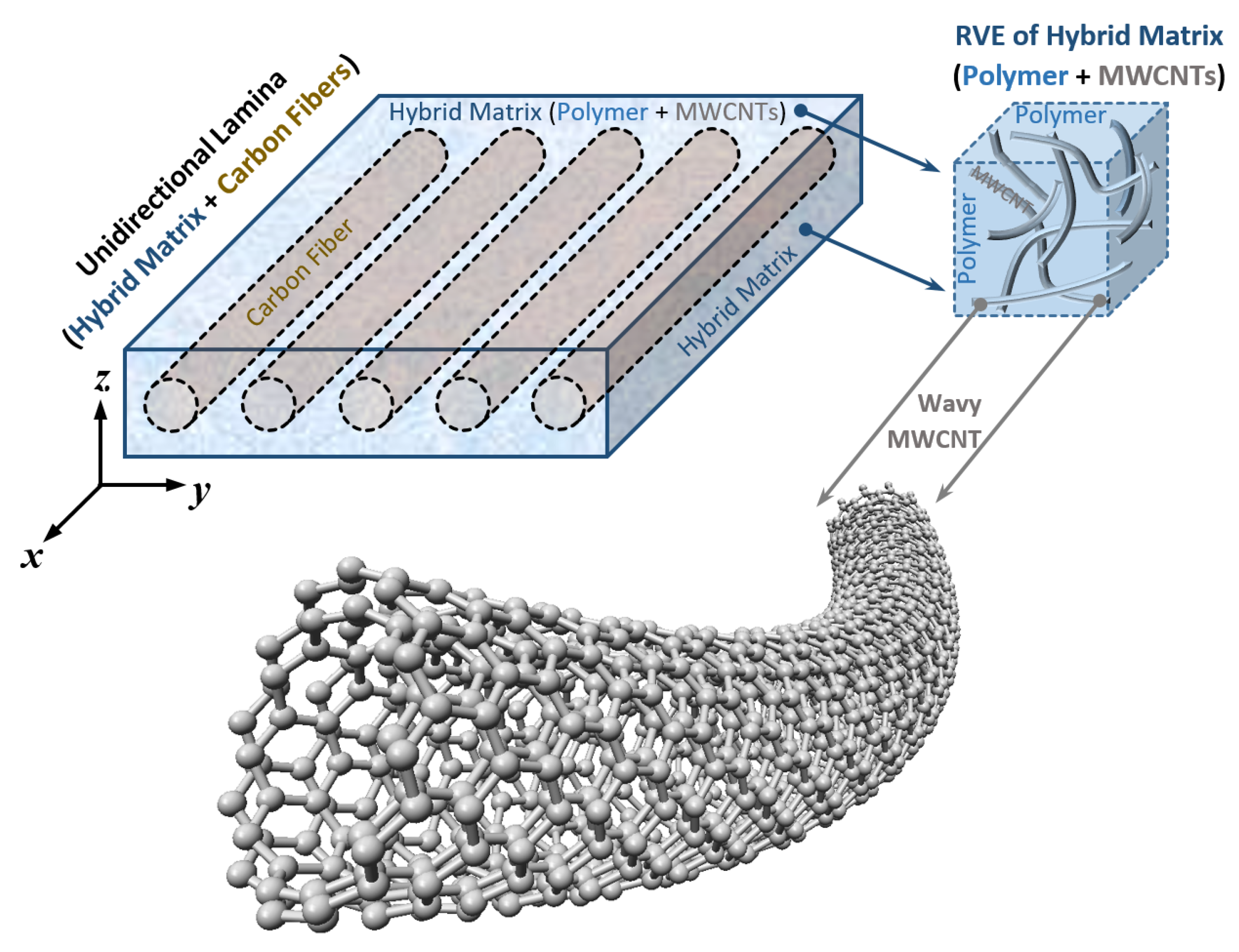
In the present work, three critical factors, including random dispersion, nonstraight shape, and agglomerated state of MWCNTs, are incorporated into the H–T model. A unidirectional carbon-fiber-reinforced composite lamina with a hybrid MWCNT–polymer matrix is shown in Figure 1.

2.1. Hybrid CNT–Polymer Matrix Elastic Constants

The elastic modulus of an aligned straight CNT-reinforced polymer nanocomposite can be predicted by using the well-established H–T micromechanical model as follows [53]:
E m - c n t = E m ( 1 + 2 R δ V c n t 1 δ V c n t ) ,
in which
R = ( L c n t d c n t ) ,
and
δ = ( E c n t / E m ) 1 ( E c n t / E m ) + 2 R ,
where Em and Ecnt are Young’s modulus of the polymer matrix and CNT, respectively. Additionally, Vcnt is the volume fraction of CNTs, while dcnt and Lcnt are the nanotube’s average outer diameter and length, respectively.
The H–T model in Equation (1) estimates the elastic modulus of straight-aligned CNT-reinforced nanocomposites with the assumption of uniform dispersion of CNTs into the polymer matrix. In most real applications, CNTs are not straight aligned, while a perfect and uniform dispersion of CNTs into the polymer matrix is very difficult to be achieved. In such cases, Equation (3) is no longer applicable. In the present study, we take into account three critical factors (orientation, waviness, and agglomeration) in our mechanical property estimations, and therefore, these factors should be incorporated into the modified H–T model.
First, an orientation factor is included in Equation (3) to calculate the random orientation of CNTs into the nanocomposite. It is assumed that a CNT is randomly oriented in two dimensions when its length is greater than the specimen thickness, resulting in fR = 1/3, and that it is randomly oriented in three dimensions when its length is much smaller than the specimen thickness, resulting in fR = 1/6. In this study, the orientation factor is considered to be fR = 1/6, and Equation (3) is rewritten as:
δ = ( f R E c n t / E m ) 1 ( f R E c n t / E m ) + 2 R ,
Second, the waviness factor is included in Equation (4) to determine the waviness of either CNTs or MWCNTs into the nanocomposite:
f W = 1 ( A W ) ,
where A is the amplitude of a wavy CNT and W is a half wavelength, as illustrated in Figure 2.
Here, the waviness factor is considered to be equal to fW = 0.6, and thus, Equation (4) takes the following form:
δ = ( f R f W E c n t / E m ) 1 ( f R f W E c n t / E m ) + 2 R ,
The H–T micromechanical model is further altered to include the CNT agglomerated state in the polymer matrix. Therefore, an agglomeration efficiency factor, fA, is added in Equation (6). In the present study, the values of α and β are considered to be 10 and 0.9, and Equation (6) may be rewritten as:
δ = ( f R f W f A E c n t / E m ) 1 ( f R f W f A E c n t / E m ) + 2 R ,
where
f A = exp ( α V β c n t ) ,
in which parameters α and β are related to the degree of CNT agglomeration.
The efficiency factors (i.e., orientation, waviness, and agglomeration of CNTs) may be adjusted by using characterization techniques. The characterization methods can be used to provide the representative average values for the efficiency factors according to the production process adopted in the manufacture of the nanocomposites.
The shear modulus of the CNT–polymer matrix, as it exhibits quasi-isotropic behavior, can be calculated by the following equation [39]:
G m - c n t = E m - c n t 2 ( υ m c n t + 1 ) ,
Similarly, regarding Poisson’s ratio for the pure and CNT–polymer matrix, it may approximately be written as [39]:
υ m - c n t = υ m ,
The density of the hybrid matrix can also be calculated from the following equation [39]:
ρ m - c n t = ρ c n t V c n t + ρ m V m ,
where ρcnt and ρm are the densities of the nanotube and matrix, respectively, and Vcnt and Vm are the volume fractions of the nanotube and matrix, respectively.
The density of the nanocomposite lamina can be calculated from the following equation [39]:
ρ c = ρ f V f + ρ m - c n t V m - c n t ,
where ρf is the density of the fibers, and Vf and Vm-cnt are the volume fractions of the fibers and hybrid (CNT-reinforced) matrix, respectively.

2.2. Unidirectional Composite Lamina Elastic Constants

Young’s modulus of a unidirectional lamina in the longitudinal direction, E1, and Poisson’s ratio, υ12, can be calculated by utilizing the rule of mixtures [39]:
E 1 = E f V f + E m - c n t V m - c n t ,
υ 12 = υ f V f + υ m - c n t V m - c n t ,
where Ef, Vf, and vf are Young’s modulus of the fiber, the volume fraction of the fiber, and Poisson’s ratio of the fiber, respectively. In this study, the volume fractions of the fibers and matrix were assumed to be 60% and 40%, respectively.
According to experimental results, the values obtained for transverse Young’s modulus, E2; Poisson’s ratio, υ23; and shear modulus, G12 and G23, are not well matched with the values calculated using the rule of mixtures. Due to these incompatibilities, semiempirical models have been developed for design purposes, such as Halpin–Tsai, as they can be used over a wide range of elastic properties and fiber volume fractions. The H–T equation for calculating these material properties is given by [39]:
P P m - c n t = ( 1 + ξ η V f 1 η V f ) ,
where Pm-cnt means the related properties of the CNT–polymer matrix, and P can be considered transverse Young’s modulus; E2, transverse Poisson’s ratio, υ23; in-plane shear modulus, G12; and out-of-plane shear modulus, G23. The parameter η is an experimental factor computed by using the next expression [39]:
η = ( P f / P m - c n t ) 1 ( P f / P m - c n t ) + ξ ,
where Pf means the related properties of the fiber. The term ξ is called reinforcing factor and depends on fiber geometry, packing geometry, and loading conditions. For circular fibers in a square array, ξ = 2 for E2, and ξ = 1 for υ23, G12, and G23, as referred in [48].

3. Finite Element Modeling

The finite element method is a numerical technique that converts an actual mechanical component into small but finite, well-defined, elastic substructures (elements). The continuous elastic behavior of each element is developed concerning its geometry and material properties. Loads can be applied within the element, on the surface of the element, or at the nodes of the element. The nodes are the essential governing entities of the element, given that they are the connection points of each element, where elastic properties are established, boundary conditions are assigned, and forces are applied [54].
In the present study, thin square composite plates were discretized by using the commercial finite element program Abaqus CAE to obtain approximate solutions and predict the elastic instability (buckling) of the laminated composite plate subjected to uniaxial and/or biaxial compression in the vertical and/or horizontal direction. The composite plates were considered thin-walled plates, balanced, while the stress–strain relationship was assumed to be linear and elastic.

3.1. Defining Material Properties

In the current study, epoxy resin 3501-6, multiwalled carbon nanotubes, and carbon fiber AS4 are chosen as matrix material, nanofillers, and fiber-reinforcing material, respectively. The material properties of the components constituting the nanocomposite material are shown in Table 1.
The material properties of MWCNT-reinforced nanocomposite lamina were calculated with the previous theoretical approaches. The volume fractions of the fiber and matrix were considered to be 60% and 40%, respectively. Following the approach presented in the previous section, the obtained engineering constants are shown in Table 2.
It is clear from the results that the elastic constants E1, E2, G12, and G23 increase by increasing Vcnt (vol%) in the polymer matrix. Specifically, there were 0.60%, 18.38%, 31.93%, and 24.21% increases in E1, E2, G12, and G23, respectively, due to the addition of 10 vol% CNTs in the polymer matrix compared with the pure laminated composite plate. Note that the mechanical properties of the nanocomposite matrix for Vcnt = 10% are reduced compared with the ones for Vcnt = 8%. Agglomeration of CNTs leads to nonhomogeneous dispersion with small assemblies of CNT reinforcements in certain points throughout the composite. This can cause a decrease in the mechanical properties, a behavior that was also observed elsewhere [53,58]. The effects of CNT orientation, waviness, and agglomeration are discussed in the following sections.

3.2. Eigenvalue Buckling Analysis

The element type used in the modeling of the laminated composite in this analysis was S4R, which is a 3D four-node, quadrilateral, stress/displacement shell element with reduced integration and a large-strain formulation. These elements allow transverse shear deformation and account for finite membrane strains and arbitrarily large rotations. Reduced integration usually provides more accurate results and significantly reduces running time, especially in three dimensions. A total of 400 elements were used in FEA, and the rectangular composite plate was divided into 20 × 20 units.
After the definition of the required finite elements, a static analysis must be carried out before the buckling one [59]. To perform the linear elastic analysis, the equilibrium equations of all elements are transformed to the global Cartesian coordinate system and then assembled in line with the requirements of nodal equilibrium and boundary conditions in the following solvable form:
K u = F ,
where K, u, and F are the assembled stiffness matrix, displacement vector, and force vector, respectively.
The eigenvalue buckling analysis is performed using the Lanczos method by imposing a reference load, Fref, to the structure. The eigenvalues can be computed from the following eigenvalue matrix equation:
[ K λ K G ] V = 0 ,
where λ is the eigenvalue that is the multiplier of the reference load, Fref, and KG is the geometric stiffness matrix formed by the loads calculated by the linear static analysis, while the vector V is the eigenvector that corresponds to the eigenvalue.
The minimum load that leads to the structural instability of the composite plate is termed critical load, Fcr, and is related with the lowest eigenvalue, λcr, as follows:
F cr = λ cr F cr ,
The nondimensional buckling load is defined as:
N ¯ = N c r α 2 Ε 2 h 3
where Ncr is the critical buckling load, E2 is transverse Young’s modulus of the plate, and α and h are the length of the side and the thickness of the plate, respectively.
Accurate knowledge of critical buckling loads is essential for a reliable and lightweight structural design [60]. To take into account the extraordinary properties of CNTs in real-world applications, CNT/polymer nanocomposites have already been introduced. Currently, polymer composites technology is the main application area for CNTs. These nanocomposites are utilized in different fields, including transportation, automotive, aerospace, defense, sporting goods, energy, and infrastructure sectors. Such a wide range of applications is due to the high durability, high strength, light weight, design, and process flexibility of these materials [61].

4. Results

The procedure outlined in the previous sections is used herein to study the influence of various involved parameters on the elastic instability (buckling) of the laminated composite. First, some comparative studies are performed to verify the accuracy and efficiency of the presented method. Afterward, the parametric studies are carried out.

4.1. Convergence Study

A convergence study was performed to determine the required mesh size N × N at which the dimensionless critical buckling load values converge. As presented in Table 3, it can be concluded that the values of nondimensional buckling load converged at 400 elements (20 × 20). Therefore, for all subsequent analyses, a mesh size of 20 × 20 was adopted.

4.2. Comparison Study

To evaluate the validity of the present FE model in terms of critical buckling load, a comparison with analytical and numerical results available in the open literature was performed. Specifically, the obtained results were set in contrast with the results published by Anish et al. [62], Nguyen-Van et al. [63], Liu et al. [6], Reddy and Phan [64], Khdeir and Librescu [65], Singh et al. [66], Sayyad and Ghugal [67], Noor [68], Vescovini and Dozio [8], Huang and Li [3], Wang et al. [1], Reddy and Khdeir [69], Hassanzadeh-Aghdam and Jamali [53], Omidi et al. [56], and Ouinas and Achour [70] based on various theories and methods.

4.2.1. Effect of Elastic Modulus Ratios

The analysis of a simply supported (SSSS) cross-ply laminated square plate stacked as [0°/90°/90°/0°] and [0°/90°/0°] under the effect of uniaxial compression was performed.
In this example, the analysis of a square plate was performed by using an a/h ratio equal to 10; an a/b ratio equal to 1, G12 = G13= 0.6E2, G23 = 0.5E2, υ12 = 0.25; and an E1/E2 elastic modulus ratio equal to 3/10/20/30 and 40, respectively. The method can deal with any material. The values of mechanical properties in this example are chosen exclusively for comparison reasons and are similar to the ones utilized in [62,63,64,65,66,67,68]. The results from the present FE model, presented in Table 4, are in very good agreement with the analytical results from the previously quoted literature.

4.2.2. Effect of Thickness Ratio

Furthermore, an analysis for a simply supported cross-ply laminated square plate stacked as [0°/90°/0°] under the effect of biaxial compression was conducted. In this comparison example, the buckling analysis of a rectangular plate was performed with a thickness ratio, a/h, equal to 10/20/50; an a/b ratio equal to 1, G12 = G13= 0.6E2, G23 = 0.5E2, υ12 = 0.25; and an E1/E2 elastic modulus ratio equal to 10 and 25. The results from the present FE model, presented in Table 5, are in very good agreement compared with the results provided by Anish et al. [62] and Vescovini and Dozio [8].

4.2.3. Effect of Mixed Boundaries

In this section, the influence of the mixed boundary conditions is considered. The plate is always simply supported (S) along the edges parallel to the y-axis, while the other edges have simply supported (S), clamped (C), or free (F) boundary conditions. The notation SSFF, for instance, refers to the simply supported condition of the two edges parallel to the y-axis and the free condition for the two edges parallel to the x-axis, as shown in Figure 3b.
The 10-layer cross-ply [0°/90°]5 laminated rectangular plate, subjected to uniaxial compression, was analyzed by using the material properties: E1/E2 = 40, α/h = 10, G12 = G13 = 0.6E2, G23 = 0.5E2, and υ12 = 0.25, α/b = 1. Table 6 contains the nondimensional buckling loads for several boundary conditions obtained by the present FEM and other analytical and numerical solutions. The data in Table 6 demonstrate a very good agreement between the present FEM and other available solutions. The fundamental buckling mode of the 10-layer [0°/90°]5 composite plate under various edge conditions is shown in Figure 3.

4.2.4. Influence of the Ply Orientation on the Critical Buckling Load

In this section, a numerical study was carried out to assess the influence of the ply orientation on the critical buckling load. An eight-layer symmetric cross-ply laminated rectangular plate, 100 mm × 100 mm × 1.016 mm, subjected to monoaxial vertical compressions and arranged in a (θ°/−θ°) lamination pattern, including different fiber orientation angles, was investigated. The plate is free (F) along the edges parallel to the y-axis, while the other edges are clamped (C), as shown in Figure 4a. The material has the following properties: E1 = 118 GPa, E2 = 10 GPa, G12 = G13 = 6.2 GPa, G23 = 4.1 GPa, υ12 = 0.237. Figure 5 represents the critical buckling loads for different orientation angles obtained by the present FEM and Ouinas and Achour FEM-based analysis [70]. A reasonable agreement may be observed. The fundamental buckling mode of a laminated composite plate, which consisted of eight plies having a (90°/−90°) pattern, is presented in Figure 4b. Figure 5 illustrates an exponential growth of the critical buckling load with an increase in fiber orientation angle from 0 to 90 degrees.
This augmentation in buckling loads is noteworthy when θ ≥ 45ο. The highest values were acquired when θ = 90°, as the lamina fibers were placed along the edges parallel to the y-axis. The lowest values of the critical buckling load were obtained when the fibers were orientated at θ = 0°, perpendicular to the applied stress.

4.2.5. Effect of MWCNT Inclusion on the Elastic Modulus

In this section, a theoretical study was conducted to assess the influence of the MWCNT inclusion on Young’s modulus of the matrix. A modified form of an H–T micromechanical model, as described in Section 2, was used to characterize the elastic modulus of MWCNT-reinforced polymer nanocomposites. For that purpose, three critical factors were incorporated into the H–T model, including random dispersion, nonstraight shape, and agglomerated state of the MWCNTs. To verify the obtained results, a comparison was made concerning the study of Hassanzadeh-Aghdam and Jamali [53] and the experimental data given by Omidi et al. [56]. Note that identical material properties were used for verification purposes. To provide novel results, the engineering constants in Table 1 were used, calculated by the theoretical approach presented in Section 2.
The composite matrix and MWCNT nanofillers have properties: LY-5052 epoxy resin: Em = 3.11 GPa, υm = 0.35, Gm = 1.152 GPa, Ecnt = 900 GPa, Lcnt = 2000 nm, and dcnt = 30 nm, respectively. The critical factors fR and fW are equal to 1/6 and 0.6, respectively. Additionally, the values of α and β are considered to be 10 and 0.9.
The variation of nanocomposite Young’s modulus with Vcnt (vol%) is presented in Figure 6. The results presented in Figure 6 show a reasonable agreement between studies. It is observed that including three critical factors simultaneously into the modified Halpin–Tsai model leads us to estimate values considerably close to the experimental data.

4.3. Buckling of Carbon-Fiber-Reinforced Composite Plates with MWCNT Inclusions

After validating the presented FE model and modified H–T model, based on the previous theories through comparison studies, a new study was carried out to analyze the effect of Vcnt (vol%) on the critical buckling load of laminated composite plates and the influence of CNT waviness and agglomeration on the elastic modulus. As an example of buckling analysis, we used the composite plate presented in the Section 4.2.4 and illustrated in Figure 4. Specific lamination patterns and boundary conditions were considered. The material properties adopted for the present analysis were assumed as defined in Table 2.

4.3.1. Influence of MWCNTs on the Elastic Modulus of the Matrix

Using the modified H–T model, a parametric study was performed to calculate Young’s modulus of MWCNT/polymer nanocomposites for several Vcnt values (vol%). The material properties adopted for the current analysis are listed in Table 1. The critical factors fR and fW are equal to 1/6 and 0.6, respectively. Additionally, the values of α and β are considered to be 10 and 0.9. The mechanical properties of an MWCNT/polymer composite obtained by the H–T equation are listed in Table 7.
The CNT/polymer nanocomposite mechanical property seems to be significantly improved as the volume fraction of MWCNT increases. For instance, for Vcnt = 2% Young’s modulus is enhanced up to 26%. It is obvious that the presence of MWCNTs in the epoxy matrix results in a positive effect on their reinforcement role, mainly for lower volume fractions.

4.3.2. Influence of MWCNT Waviness on the Elastic Modulus of the Matrix

Using the modified H–T equation, a parametric study was carried out to determine Young’s modulus of CNT/polymer nanocomposites for various waviness efficiency factors. The variation of Young’s modulus with the CNT waviness efficiency factor is presented in Figure 7. The CNT/polymer nanocomposite mechanical property is shown to be significantly sensitive to the CNT waviness. It is observed that the elastic modulus of the CNT/polymer nanocomposite increases when the CNT waviness correction factor increases. The presence of CNT waviness in the matrix results in a negative effect on its reinforcement role.

4.3.3. Influence of MWCNT Agglomeration on the Elastic Modulus of the Matrix

Using the modified H–T equation, a parametric study was carried out to determine Young’s modulus of CNT/polymer nanocomposites for agglomeration factors. The variation of Young’s modulus with the CNT agglomeration factor is presented in Figure 8. The CNT/polymer nanocomposite mechanical property is shown to be significantly sensitive to the CNT agglomeration. It is observed that the elastic modulus of the CNT/polymer nanocomposite increases when the CNT agglomeration factor increases. The presence of CNT agglomeration in the matrix results in a negative effect on its reinforcement role.

4.3.4. Influence of MWCNT Inclusion on the Critical Buckling Load of Composite Plates

A numerical study was carried out to assess the influence of MWCNT inclusion on the critical buckling load. An eight-layer symmetric cross-ply laminated rectangular plate, 100 mm × 100 mm × 1.016 mm, subjected to monoaxial vertical compressions and stacked as a (θ°/−θ°) lamination scheme with different fiber orientation angles and MWCNT inclusions was investigated. The plate has free (FFCC) boundary conditions, as shown in Figure 4a. The utilized material properties are given in Table 1 and Table 2. It is assumed that the critical factors are fW = 0.6, fR = 1/6, and fA = exp(−αVβcnt), where α = 10 and β = 0.9. The values of the critical buckling loads with the MWCNT volume fraction are listed in Table 8.
Given the present results, we observe that the laminated composite plate with Vcnt = 10% shows 0.97%, 1.52%, 2.36%, 4.19%, 6.01%, 9.19%, 14.89%, 19.08%, 19.11%, and 18.41% increases in its critical buckling load values in 90, 80, 70, 60, 50, 40, 30, 20, 10, and 0 degrees, respectively, compared with the pure laminated composite plate. The results show that the critical buckling load of the CNT/polymer nanocomposite is significantly sensitive to the CNT inclusion mainly when θ ≤ 45°. The presence of CNT in the matrix results in a positive effect on its reinforcement role.

4.3.5. Critical Buckling Load for Different States of Waviness

Experimental studies have shown that most CNTs in nanocomposites exist in a curved state. This is partially true because CNTs have very low bending stiffness due to their small tube diameter (~1 nm) [71]. To examine the waviness effect of curved CNTs on the critical buckling load of CNT-reinforced composites, the modified H–T micromechanics model was employed for Vcnt = 10%. The variation of the critical buckling load with different MWCNT waviness factors is presented in Figure 9. The buckling response of laminated nanocomposite plates is shown to be considerably affected by the MWCNT waviness. Specifically, critical buckling load without waviness effect (fW = 1) shows 1.34%, 2.02%, 3.08%, 5.23%, 7.46%, 11.04%, 16.50%, 19.96%, 19.89%, and 19.28% decreases in its values in 90, 80, 70, 60, 50, 40, 30, 20, 10, and 0 degrees, respectively, compared with the critical buckling load calculated for the waviness factor (fW = 0.2). The results show that the critical buckling load of the CNT/polymer nanocomposite is significantly sensitive to the curved form of CNTs mainly when θ ≤ 45ο. The presence of CNT waviness in the matrix results in a negative effect on its reinforcement role.

4.3.6. Critical Buckling Load for Different States of Agglomeration

CNTs have low bending stiffness due to their small diameter and small elastic modulus in the radial direction, as well as their high aspect ratio, which makes CNTs easy to agglomerate in a polymer matrix [71]. To examine the influence of the agglomeration of CNTs on the critical buckling load of CNT-reinforced composites, the modified H–T micromechanics model was employed for a 10% MWCNT volume fraction. The variation of the critical buckling load with different MWCNT agglomeration factors is presented in Figure 10. The buckling response of laminated nanocomposite plates seems to be considerably affected by the MWCNT agglomeration. Specifically, critical buckling load without agglomeration effect (α = 0) shows 2.45%, 3.43%, 5.10%, 8.25%, 11.80%, 17.21%, 24.51%, 28.83%, 28.68%, and 27.89% decreases in its values in 90, 80, 70, 60, 50, 40, 30, 20, 10, and 0 degrees, respectively, compared with the critical buckling load calculated for an agglomeration factor, α = 15. The results show that the critical buckling load of the CNT/polymer nanocomposite is significantly sensitive to the dispersion of CNTs in the matrix mainly when θ ≤ 45ο. The presence of CNT agglomeration in the matrix results in a negative effect on its reinforcement role.

5. Conclusions

In this work, the critical buckling load of laminated composite plates reinforced by CNTs was investigated using FEM. The modified polymer matrix with different CNT volume fractions was theoretically evaluated using the modified H–T micromechanical model considering the effects of the widely observed waviness, agglomeration, and orientation of CNTs. The results obtained from FEM were in good agreement with those from the open literature. The predictions of the modified H–T model were compared with the corresponding available experimental and analytical results found in the open literature to verify the applicability of the approach. The comparisons showed a very good agreement.
The CNT nanoparticles considerably influenced the engineering constants that were used to determine material properties such as Young’s modulus, shear modulus, and Poisson’s ratio of the composite lamina. The comparison between the results regarding the pure and reinforced matrix indicates that the CNTs enhance the matrix material properties. However, it is established that two critical factors, such as the waviness and agglomeration of the CNTs, may considerably reduce the stiffening effect of CNTs. According to the numerical outcome, the following conclusions can be drawn:
  • Young’s modulus of the CNT/polymer matrix appears to be considerably affected by the waviness and agglomeration state of the CNTs.
  • Young’s modulus of the CNT/polymer matrix can be improved by up to 49.18% with the addition of 10% by volume CNTs, considering varying factors such as orientation, waviness, and agglomeration of the CNTs.
  • The mechanical properties E1, E2, G12, and G23 of the composite lamina can be increased by up to 0.60%, 18.38%, 31.93%, and 24.21%, respectively, with the addition of 10% by volume CNTs in the matrix, considering orientation, waviness, and agglomeration effects in the calculations.
  • The critical buckling load rises exponentially regarding the increase of fiber orientation angle (θο) for an eight-layer symmetric cross-ply laminated rectangular plate stacked as (θο/−θο).
  • In consequence of adding 10% by volume CNTs into the conventional composite, the critical buckling load of the laminated composite plate showed great improvements. These enhancements measured from 0.97% to 19.11% regarding the critical buckling load, taking into account critical factors, such as the waviness and agglomeration of the CNTs.
  • The critical buckling load of the laminated nanocomposite plate seems to be significantly affected by the waviness and agglomeration state of CNTs. The presence of CNT waviness and agglomeration in the polymer matrix results in a negative effect on its reinforcing role.
Polymer nanocomposites represent a promising class of engineering materials. Besides nanofiller properties and geometrical characteristics, the major factors for the performance of CNT/reinforced nanocomposites are the state of the agglomeration, waviness, orientation and the interface between the polymer matrix and nanofiller. These key factors appear to have a crucial role in the overall behavior of nanocomposites and, thus, are the focus of the scientific research community. This work could be a guide concerning the efficient design and development of composite structures and devices with carbon nanotube inclusions.

Author Contributions

Conceptualization, S.K.G.; methodology, S.K.G.; software, P.A.A. and S.I.M.; validation, P.A.A.; formal analysis, G.I.G.; investigation, P.A.A.; resources, A.F.; data curation, P.A.A.; writing—original draft preparation, P.A.A. and A.F.; writing—review and editing, S.I.M.; visualization, G.I.G.; supervision, S.K.G.; project administration, S.K.G. All authors have read and agreed to the published version of the manuscript.

Funding

This research received no external funding.

Conflicts of Interest

The authors declare no conflict of interest.

References

  1. Wang, J.; Liew, K.M.; Tan, M.-J.; Rajendran, S. Analysis of rectangular laminated composite plates via FSDT meshless method. Int. J. Mech. Sci. 2002, 44, 1275–1293. [Google Scholar] [CrossRef]
  2. Liu, G.R.; Chen, X.L.; Reddy, J.N. Buckling of symmetrically laminated composite plates using the element-free galerkin method. Int. J. Struct. Stab. Dyn. 2002, 2, 281–294. [Google Scholar] [CrossRef]
  3. Huang, Y.; Li, Q. Bending and buckling analysis of antisymmetric laminates using the moving least square differential quadrature method. Comput. Methods Appl. Mech. Eng. 2004, 193, 3471–3492. [Google Scholar] [CrossRef]
  4. Shukla, K.K.; Nath, Y.; Kreuzer, E.; Kumar, K.V. Buckling of Laminated Composite Rectangular Plates. J. Aerosp. Eng. 2005, 18, 215–223. [Google Scholar] [CrossRef]
  5. Ungbhakorn, V.; Singhatanadgid, P. Buckling analysis of symmetrically laminated composite plates by the extended Kantorovich method. Compos. Struct. 2006, 73, 120–128. [Google Scholar] [CrossRef]
  6. Liu, L.; Chua, L.; Ghista, D. Mesh-free radial basis function method for static, free vibration and buckling analysis of shear deformable composite laminates. Compos. Struct. 2007, 78, 58–69. [Google Scholar] [CrossRef]
  7. Neves, A.; Ferreira, A.; Carrera, E.; Cinefra, M.; Roque, C.; Jorge, R.N.; Soares, C.M.M. Static, free vibration and buckling analysis of isotropic and sandwich functionally graded plates using a quasi-3D higher-order shear deformation theory and a meshless technique. Compos. Part B Eng. 2013, 44, 657–674. [Google Scholar] [CrossRef] [Green Version]
  8. Vescovini, R.; Dozio, L. Exact refined buckling solutions for laminated plates under uniaxial and biaxial loads. Compos. Struct. 2015, 127, 356–368. [Google Scholar] [CrossRef] [Green Version]
  9. Turvey, G.J.; Wittrick, W.H. The Large Deflection and Post-Buckling Behaviour of Some Laminated Plates. Aeronaut. Q. 1973, 24, 77–86. [Google Scholar] [CrossRef]
  10. Harris, G. The buckling and post-buckling behaviour of composite plates under biaxial loading. Int. J. Mech. Sci. 1975, 17, 187–202. [Google Scholar] [CrossRef]
  11. Prabhakara, M.K.; Chia, C.Y. Post-Buckling Behaviour of Rectangular Orthotropic Plates. J. Mech. Eng. Sci. 1973, 15, 25–33. [Google Scholar] [CrossRef]
  12. Prabhakara, M.K.; Chia, C.Y. Postbuckling of angle-ply and anisotropic plates. Arch. Appl. Mech. 1976, 45, 131–139. [Google Scholar] [CrossRef]
  13. Zhang, Y.; Matthews, F.L. Postbuckling behavior of anisotropic laminated plates under pure shear and shear combined with compressive loading. AIAA J. 1984, 22, 281–286. [Google Scholar] [CrossRef]
  14. Stein, M. Postbuckling of orthotropic composite plates loaded in compression. AIAA J. 1983, 21, 1729–1735. [Google Scholar] [CrossRef]
  15. Kim, K. Buckling behaviour of composite panels using the finite element method. Compos. Struct. 1996, 36, 33–43. [Google Scholar] [CrossRef]
  16. Shojaee, S.; Valizadeh, N.; Izadpanah, E.; Bui, T.; Vu, T.-V. Free vibration and buckling analysis of laminated composite plates using the NURBS-based isogeometric finite element method. Compos. Struct. 2012, 94, 1677–1693. [Google Scholar] [CrossRef]
  17. Ounis, H.; Tati, A.; Benchabane, A. Thermal buckling behavior of laminated composite plates: A finite-element study. Front. Mech. Eng. 2014, 9, 41–49. [Google Scholar] [CrossRef]
  18. Noor, A.K. Finite element buckling and postbuckling analyses. In Buckling and Postbuckling of Composite Plates; Turvey, G.J., Marshall, I.H., Eds.; Springer: Dordrecht, The Netherlands, 1995; pp. 58–107. [Google Scholar] [CrossRef]
  19. Ashton, J.; Love, T. Experimental Study of the Stability of Composite Plates. J. Compos. Mater. 1969, 3, 230–242. [Google Scholar] [CrossRef]
  20. Gopalan, V.; Suthenthiraveerappa, V.; David, J.; Subramanian, J.; Annamalai, A.; Jen, C.-P. Experimental and Numerical Analyses on the Buckling Characteristics of Woven Flax/Epoxy Laminated Composite Plate under Axial Compression. Polymers 2021, 13, 995. [Google Scholar] [CrossRef]
  21. Galos, J. Thin-ply composite laminates: A review. Compos. Struct. 2020, 236, 111920. [Google Scholar] [CrossRef]
  22. Bajpai, P.K.; Singh, I. Reinforced Polymer Composites: Processing, Characterization and Post Life Cycle Assessment; John Wiley & Sons: Hoboken, NJ, USA, 2019. [Google Scholar]
  23. Stamoulis, K.; Georgantzinos, S.K.; Giannopoulos, G. Damage characteristics in laminated composite structures subjected to low-velocity impact. Int. J. Struct. Integr. 2019, 11, 670–685. [Google Scholar] [CrossRef]
  24. Georgantzinos, S.K. The Role of Multi-Scale Finite Element Methods in Analysis and Design of Advanced Mechanical and Aerospace Structures. IJMPERD 2019, 9, 805–808. [Google Scholar]
  25. Kumar, S.K.; Krishnamoorti, R. Nanocomposites: Structure, Phase Behavior, and Properties. Annu. Rev. Chem. Biomol. Eng. 2010, 1, 37–58. [Google Scholar] [CrossRef] [Green Version]
  26. Camargo, P.; Satyanarayana, K.G.; Wypych, F. Nanocomposites: Synthesis, structure, properties and new application opportunities. Mater. Res. 2009, 12, 1–39. [Google Scholar] [CrossRef] [Green Version]
  27. Zhao, J.; Wu, L.; Zhan, C.; Shao, Q.; Guo, Z.; Zhang, L. Overview of polymer nanocomposites: Computer simulation understanding of physical properties. Polymer 2017, 133, 272–287. [Google Scholar] [CrossRef]
  28. Isaac, C.W.; Ezekwem, C. A review of the crashworthiness performance of energy absorbing composite structure within the context of materials, manufacturing and maintenance for sustainability. Compos. Struct. 2021, 257, 113081. [Google Scholar] [CrossRef]
  29. Spanos, K.; Georgantzinos, S.; Anifantis, N. Mechanical properties of graphene nanocomposites: A multiscale finite element prediction. Compos. Struct. 2015, 132, 536–544. [Google Scholar] [CrossRef]
  30. Mallick, P.K. Fiber-Reinforced Composites: Materials, Manufacturing, and Design; CRC Press: Boca Raton, FL, USA, 2007. [Google Scholar]
  31. Siochi, E.J.; Harrison, J.S. Structural nanocomposites for aerospace applications. MRS Bull. 2015, 40, 829–835. [Google Scholar] [CrossRef] [Green Version]
  32. Xu, A. Airbus Extends Technology Research with Chinese Partners. Available online: https://www.airbus.com/newsroom/press-releases/en/2018/07/airbus-extends-technology-research-with-chinese-partners.html (accessed on 5 July 2018).
  33. Mandal, L.; Verma, B.; Patel, P.K. Review on polymer nanocomposite for ballistic & aerospace applications. Mater. Today Proc. 2020, 26, 3161–3166. [Google Scholar] [CrossRef]
  34. Yip, M.-C.; Lin, Y.-C.; Wu, C.-L. Effect of Multi-Walled Carbon Nanotubes Addition on Mechanical Properties of Polymer Composites Laminate. Polym. Polym. Compos. 2011, 19, 131–140. [Google Scholar] [CrossRef]
  35. Georgantzinos, S.K.; Giannopoulos, G.I. Thermomechanical buckling of single walled carbon nanotubes by a structural mechanics method. Diam. Relat. Mater. 2017, 80, 27–37. [Google Scholar] [CrossRef]
  36. Georgantzinos, S.K. A New Finite Element for an Efficient Mechanical Analysis of Graphene Structures Using Computer Aided Design/Computer Aided Engineering Techniques. J. Comput. Theor. Nanosci. 2017, 14, 5347–5354. [Google Scholar] [CrossRef]
  37. Georgantzinos, S.; Stamoulis, K.P.; Markolefas, S. Mechanical Response of Hybrid Laminated Polymer Nanocomposite Structures: A Multilevel Numerical Analysis. SAE Int. J. Aerosp. 2020, 13, 1–13. [Google Scholar] [CrossRef]
  38. Georgantzinos, S.K.; Markolefas, S.I.; Mavrommatis, S.A.; Stamoulis, K. Finite element modelling of carbon fiber—Carbon nanostructure—Polymer hybrid composite structures. MATEC Web Conf. 2020, 314, 02004. [Google Scholar] [CrossRef]
  39. Georgantzinos, S.K.; Giannopoulos, G.I.; Markolefas, S.I. Vibration Analysis of Carbon Fiber-Graphene-Reinforced Hybrid Polymer Composites Using Finite Element Techniques. Materials 2020, 13, 4225. [Google Scholar] [CrossRef] [PubMed]
  40. Psarras, G.C. Nanographite-Polymer Composites. In Carbon Nanomaterials Sourcebook: Nanoparticles, Nanocapsules, Nanofibers, Nanoporous Structures, and Nanocomposites, 1st ed.; Sattler, K.D., Ed.; CRC Press: Boca Raton, FL, USA, 2016; Volume 2, pp. 647–673. [Google Scholar]
  41. Civalek, Ö.; Dastjerdi, S.; Akgöz, B. Buckling and free vibrations of CNT-reinforced cross-ply laminated composite plates. Mech. Based Des. Struct. Mach. 2020, 1–18. [Google Scholar] [CrossRef]
  42. Civalek, Ö.; Dastjerdi, S.; Akbaş, Ş.D.; Akgöz, B. Vibration analysis of carbon nanotube-reinforced composite microbeams. Math. Methods Appl. Sci. 2021. [Google Scholar] [CrossRef]
  43. Jalaei, M.; Civalek, Ö. On dynamic instability of magnetically embedded viscoelastic porous FG nanobeam. Int. J. Eng. Sci. 2019, 143, 14–32. [Google Scholar] [CrossRef]
  44. Akbaş, Ş.D.; Ersoy, H.; Akgöz, B.; Civalek, Ö. Dynamic Analysis of a Fiber-Reinforced Composite Beam under a Moving Load by the Ritz Method. Mathematics 2021, 9, 1048. [Google Scholar] [CrossRef]
  45. Craveiro, D.S.; Loja, M.A.R. An Assessment of Thick Nanocomposite Plates’ Behavior under the Influence of Carbon Nanotubes Agglomeration. J. Compos. Sci. 2021, 5, 41. [Google Scholar] [CrossRef]
  46. Rafiee, R.; Eskandariyun, A. Predicting Young’s modulus of agglomerated graphene/polymer using multi-scale modeling. Compos. Struct. 2020, 245, 112324. [Google Scholar] [CrossRef]
  47. Georgantzinos, S.; Antoniou, P.; Markolefas, S. A Multi-Scale Method for Designing Hybrid Fiber-Reinforced Composite Drive Shafts with Carbon Nanotube Inclusions. J. Compos. Sci. 2021, 5, 157. [Google Scholar] [CrossRef]
  48. Taş, H.; Soykok, I.F. Effects of carbon nanotube inclusion into the carbon fiber reinforced laminated composites on flexural stiffness: A numerical and theoretical study. Compos. Part B Eng. 2019, 159, 44–52. [Google Scholar] [CrossRef]
  49. Lei, Z.; Liew, K.M.; Yu, J. Buckling analysis of functionally graded carbon nanotube-reinforced composite plates using the element-free kp-Ritz method. Compos. Struct. 2013, 98, 160–168. [Google Scholar] [CrossRef]
  50. Qiu, L.; Zhang, X.; Guo, Z.; Li, Q. Interfacial heat transport in nano-carbon assemblies. Carbon 2021, 178, 391–412. [Google Scholar] [CrossRef]
  51. Qiu, L.; Zhu, N.; Feng, Y.; Zhang, X.; Wang, X. Interfacial thermal transport properties of polyurethane/carbon nanotube hybrid composites. Int. J. Heat Mass Transf. 2020, 152, 119565. [Google Scholar] [CrossRef]
  52. Qiu, L.; Guo, P.; Yang, X.; Ouyang, Y.; Feng, Y.; Zhang, X.; Zhao, J.; Zhang, X.; Li, Q. Electro curing of oriented bismaleimide between aligned carbon nanotubes for high mechanical and thermal performances. Carbon 2019, 145, 650–657. [Google Scholar] [CrossRef]
  53. Hassanzadeh-Aghdam, M.K.; Jamali, J. A new form of a Halpin–Tsai micromechanical model for characterizing the mechanical properties of carbon nanotube-reinforced polymer nanocomposites. Bull. Mater. Sci. 2019, 42, 117. [Google Scholar] [CrossRef] [Green Version]
  54. Budynas, R.G.; Nisbett, J.K.; Shigley, J.E. Shigley’s Mechanical Engineering Design; McGraw-Hill: New York, NY, USA, 2011; pp. 953–975. [Google Scholar]
  55. Soden, P.D.; Hinton, M.J.; Kaddour, A.S. Lamina properties, lay-up configurations and loading conditions for a range of fibre reinforced composite laminates. In Failure Criteria in Fibre-Reinforced-Polymer Composites, 1st ed.; Hinton, M.J., Kaddour, A.S., Soden, P.D., Eds.; Elsevier Ltd: Amsterdam, The Netherlands, 2004; Chapter 2.1; pp. 30–51. [Google Scholar]
  56. Omidi, M.; D.T., H.R.; Milani, A.S.; Seethaler, R.J.; Arasteh, R. Prediction of the mechanical characteristics of multi-walled carbon nanotube/epoxy composites using a new form of the rule of mixtures. Carbon 2010, 48, 3218–3228. [Google Scholar] [CrossRef]
  57. Rafiee, M.; Rafiee, J.; Wang, Z.; Song, H.; Yu, Z.-Z.; Koratkar, N. Enhanced Mechanical Properties of Nanocomposites at Low Graphene Content. ACS Nano 2009, 3, 3884–3890. [Google Scholar] [CrossRef] [PubMed]
  58. Rubel, R.I.; Ali, H.; Jafor, A.; Alam, M. Carbon nanotubes agglomeration in reinforced composites: A review. AIMS Mater. Sci. 2019, 6, 756–780. [Google Scholar] [CrossRef]
  59. Abaqus Documentation—MIT. Available online: https://abaqus-docs.mit.edu/2017/English/SIMACAEANLRefMap/simaanl-c-eigenbuckling.htm#simaanl-c-eigenbuckling-t-GeneralEigenvalueBuckling-sma-topic1 (accessed on 20 August 2021).
  60. Leissa, A. Buckling of composite plates. Compos. Struct. 1983, 1, 51–66. [Google Scholar] [CrossRef]
  61. Choudhary, V.; Gupta, A. Polymer/Carbon Nanotube Nanocomposites, Carbon Nanotubes-Polymer Nanocomposites; Yellampalli, S., Ed.; IntechOpen: London, UK, 2011. [Google Scholar] [CrossRef] [Green Version]
  62. Anish; Chaubey, A.; Kumar, A.; Kwiatkowski, B.; Barnat-Hunek, D.; Widomski, M.K. Bi-Axial Buckling of Laminated Composite Plates Including Cutout and Additional Mass. Materials 2019, 12, 1750. [Google Scholar] [CrossRef] [PubMed] [Green Version]
  63. Nguyen-Van, H.; Mai-Duy, N.; Karunasena, W.; Tran-Cong, T. Buckling and vibration analysis of laminated composite plate/shell structures via a smoothed quadrilateral flat shell element with in-plane rotations. Comput. Struct. 2011, 89, 612–625. [Google Scholar] [CrossRef] [Green Version]
  64. Reddy, J.; Phan, N. Stability and vibration of isotropic, orthotropic and laminated plates according to a higher-order shear deformation theory. J. Sound Vib. 1985, 98, 157–170. [Google Scholar] [CrossRef]
  65. Khdeir, A.; Librescu, L. Analysis of symmetric cross-ply laminated elastic plates using a higher-order theory: Part II—Buckling and free vibration. Compos. Struct. 1988, 9, 259–277. [Google Scholar] [CrossRef]
  66. Singh, S.; Singh, J.; Shukla, K.K. Buckling of laminated composite plates subjected to mechanical and thermal loads using meshless collocations. J. Mech. Sci. Technol. 2013, 27, 327–336. [Google Scholar] [CrossRef]
  67. Sayyad, A.S.; Ghugal, Y.M. On the Buckling of Isotropic, Transversely Isotropic and Laminated Composite Rectangular Plates. Int. J. Struct. Stab. Dyn. 2014, 14, 1450020. [Google Scholar] [CrossRef]
  68. Noor, A.K. Stability of multilayered composite plates. Fibre Sci. Technol. 1975, 8, 81–89. [Google Scholar] [CrossRef]
  69. Reddy, J.N.; Khdeir, A.A. Buckling and vibration of laminated composite plates using various plate theories. AIAA J. 1989, 27, 1808–1817. [Google Scholar] [CrossRef]
  70. Ouinas, D.; Achour, B. Buckling analysis of laminated composite plates [(θ/-θ)] containing an elliptical notch. Compos. Part B: Eng. 2013, 55, 575–579. [Google Scholar] [CrossRef]
  71. Shi, D.-L.; Feng, X.-Q.; Huang, Y.Y.; Hwang, K.-C.; Gao, H. The Effect of Nanotube Waviness and Agglomeration on the Elastic Property of Carbon Nanotube-Reinforced Composites. J. Eng. Mater. Technol. 2004, 126, 250–257. [Google Scholar] [CrossRef]
Figure 1. Unidirectional fiber-reinforced composite lamina with MWCNT inclusion.
Nanomaterials 11 02261 g001
Figure 2. Schematic illustration of a curved CNT.
Nanomaterials 11 02261 g002
Figure 3. Fundamental buckling mode of cross-ply 10-layer [0°/90°]5 square composite plates with a variety of boundary conditions. The boundary conditions of each plate are as follows: (a) SSSS, (b) SSFF, (c) SSCC, (d) SSSC, (e) SSFC, (f) SSFS, and the corresponding values of N ¯ : (a) 25.8350, (b) 11.9720, (c) 34.0600, (d) 32.1795, (e) 14.1590, (f) 12.2860.
Nanomaterials 11 02261 g003
Figure 4. Buckling simulation of an eight-layer symmetric cross-ply laminated rectangular plate (a) meshed model (front view) and (b) buckled model (isometric view) under free-free-clamped-clamped boundary conditions subjected to stress, σ = 1 N/mm.
Nanomaterials 11 02261 g004
Figure 5. Critical buckling load as a function of fiber orientation angle (θο). The diagram shows the effect of fiber orientation angle on the critical buckling load by changing the (θ°/−θ°) pattern. To ensure the validity of the process, identical material properties were employed.
Nanomaterials 11 02261 g005
Figure 6. Young’s modulus of CNT-reinforced matrix as a function of Vcnt (vol%). The diagram shows the effect of MWCNT inclusion on Young’s modulus of the matrix by changing the volume fraction. To ensure the validity of the process, identical material properties were employed.
Nanomaterials 11 02261 g006
Figure 7. Young’s modulus of CNT-reinforced matrix as a function of Vcnt (vol%) for various fw waviness factors. The diagram shows the effect of waviness factors on Young’s modulus (GPa) by changing the Vcnt (vol%). Young’s modulus of an MWCNT/polymer composite obtained from a modified Halpin–Tsai model concerning the following properties: Em = 4.20 GPa, Ecnt = 900 GPa, Lcnt = 2000 nm, dcnt = 30 nm, fR = 1/6, and fA = exp(−αVβcnt), where α = 10 and β = 0.9.
Nanomaterials 11 02261 g007
Figure 8. Young’s modulus of CNT-reinforced matrix as a function of Vcnt (vol%) for various fA agglomeration factors calculated from the equation fA = exp(−αVβcnt), where α ranges from 0 to 15 and β = 0.9. Young’s modulus of MWCNT/polymer composite obtained from the modified Halpin–Tsai model concerning the following properties: Em = 4.20 GPa, Ecnt = 900 GPa, Lcnt = 2000 nm, dcnt = 30 nm, fW = 0.6, and fR = 1/6.
Nanomaterials 11 02261 g008
Figure 9. Critical buckling load as a function of fiber orientation angle for Vcnt = 10% and various fW waviness factors.
Nanomaterials 11 02261 g009
Figure 10. Critical buckling load as a function of fiber orientation angle for Vcnt = 10% and various agglomeration factors, fA.
Nanomaterials 11 02261 g010
Table 1. Materials properties of the components.
Carbon Fiber AS4 [55]Epoxy Resin 3501-6 [55]MWCNTs [53,56,57]
Ef11 (GPa)225Em (GPa)4.2Ecnt (GPa)900
Ef22 (GPa)15Gm (GPa)1.567Lcnt (nm)2000
Gf12 (GPa)15υm0.34dcnt (nm)30
Gf23 (GPa)7ρm (g/cm3)1.25ρcnt (g/cm3)2.25
υf120.20
υf230.40
ρf (g/cm3)1.80
Table 2. Mechanical properties of MWCNT-reinforced nanocomposite matrix.
Vcnt (vol%)E1 (GPa)E2 (GPa)G12 (GPa)G23 (GPa)υ12υ23ρ (g/cm3)
0.00136.6809.0264.5373.4920.260.371.580
0.25136.7519.1944.6763.5770.260.371.581
0.50136.8189.3454.8033.6540.260.371.582
1.00136.9389.6065.0253.7860.260.371.584
1.50137.0429.8235.2133.8960.260.371.586
2.00137.13310.0035.3723.9890.260.371.588
3.00137.27910.2815.6194.1310.260.371.592
4.00137.38510.4735.7924.2290.260.371.596
6.00137.50510.6825.9824.3360.260.371.604
8.00137.53510.7346.0294.3630.260.371.612
10.00137.50610.6855.9854.3380.260.371.620
Table 3. Convergence study of nondimensional buckling loads, N ¯ = N c r α 2 / Ε 2 h 3 , for simply supported four-layered [0°/90°/90°/0°] cross-ply laminated rectangular plate under uniaxial compressions with different side-to-thickness ratios, a/h (Ε1/Ε2 = 40, G12 = G13 = 0.6E2, G23 = 0.5E2, υ12 = 0.25, α/b = 1).
Discretization
(No. of Elements)
MethodSide-to-Thickness Ratio, a/h
102050100
Present (4 × 4)FEA24.823534.699239.230039.9845
Present (6 × 6)FEA23.710532.822836.960037.6475
Present (8 × 8)FEA23.330032.189236.210636.8820
Present (10 × 10)FEA23.154031.895235.867536.5350
Present (14 × 14)FEA23.000531.635235.565636.2340
Present (20 × 20)FEA22.919031.494835.399436.0720
Table 4. Comparison of nondimensional buckling loads, N ¯ = N c r α 2 / Ε 2 h 3 , for simply supported cross-ply laminated rectangular plates under uniaxial compressions (G12 = G13 = 0.6E2, G23 = 0.5E2, υ12 = 0.25, α/b = 1, α/h = 10).
(Nx,Ny)LaminationSourceModulus Ratio, E1/E2
310203040
(1, 0)[0°/90°/90°/0°]Present4.99709.580014.950019.303522.9190
Anish et al. [62]5.31979.808715.102519.429523.0565
Nguyen-Van et al. [63]5.32109.809015.064019.339022.9120
Liu et al. (TSDT) [6]5.412010.013015.309019.778023.4120
Liu et al. (FSDT) [6]5.40109.985015.374019.537023.1540
Reddy and Phan (HSDT) [64]5.11439.774015.298019.957023.3400
Khdeir and Librescu (HSDT) [65]5.442010.026015.418019.813023.4890
(1, 0)[0°/90°/0°]Present4.99459.486014.567018.548521.7640
Anish et al. [62]5.31429.698214.692718.634321.8415
Singh et al. (GRBF) [66]5.37919.826714.970719.099522.5134
Singh et al. (MQRBF) [66]5.41089.895615.032619.122722.4881
Sayyad and Ghugal (TSDT) [67]N/A9.922615.002919.001822.3298
Noor (3D Elasticity) [68]5.30449.762115.019119.304022.8807
Table 5. Comparison of nondimensional buckling loads, N ¯ = N c r α 2 / Ε 2 h 3 , for simply supported cross-ply laminated rectangular plates under biaxial compressions (G12 = G13 = 0.6E2, G23 = 0.5E2, υ12 = 0.25, α/b = 1).
(Nx,Ny)E1/E2SourceThickness Ratio, α/h
102050
(1, 1)10Present4.74215.41925.6901
Anish et al. [62]4.84415.48905.7084
Vescovini and Dozio [8]4.90955.50825.7063
(1, 1)25Present7.86409.865610.7262
Anish et al. [62]7.906610.085210.7040
Vescovini and Dozio [8]8.682010.876811.7320
Table 6. Comparison of nondimensional buckling loads, N ¯ = N c r α 2 / Ε 2 h 3 , for 10-layer cross-ply [0°/90°]5 laminated rectangular plates with various mixed boundaries subjected to uniaxial compressions (E1/E2 = 40, α/h = 10, G12 = G13 = 0.6E2, G23 = 0.5E2, υ12 = 0.25, α/b = 1).
(Nx,Ny)SourceBoundary Conditions
SSSSSSFFSSCCSSSCSSFCSSFS
(1, 0)Present25.835011.972034.060032.179514.159012.2860
Nguyen-Van et al. [63]25.534012.131034.531032.874014.356012.5430
Huang and Li [3]25.338012.030034.6040---
Wang et al. [1]25.612012.177035.045032.829014.443012.6080
Reddy and Khdeir HSDT (Exact) [69]25.423012.077035.376032.885014.351012.5060
Reddy and Khdeir HSDT (FEM) [69]25.828012.248036.657033.662014.568012.6990
Reddy and Khdeir FSDT (Exact) [69]25.450012.092034.837032.614014.358012.5240
Reddy and Khdeir FSDT (FEM) [69]25.647012.226036.129033.970014.480012.6610
Table 7. Young’s modulus of CNT-reinforced matrix obtained from modified H–T model concerning orientation, waviness, and agglomeration factors for different Vcnt values (vol%) (Em = 4.20 GPa, Ecnt = 900 GPa, Lcnt = 2000 nm, dcnt = 30 nm, fW = 0.6, fR = 1/6, fA = exp(-αVβcnt) where α = 10 and β = 0.9).
Vcnt (vol%)Em-cnt (GPa)Increase (%)
0.004.20000.00
0.254.37874.25
0.504.54478.21
1.004.844015.33
1.505.104921.55
2.005.331826.95
3.005.696935.64
4.005.962341.96
6.006.261549.08
8.006.337450.89
10.006.265649.18
Table 8. Critical buckling load (N/mm) of the present study with material properties taken from Table 2 for different Vcnt values (vol%).
Lamination (θ°/−θ°)Vcnt (vol%)
0.000.250.501.001.502.003.004.006.008.0010.00
03.1723.2303.2833.3753.4523.5153.6133.6813.7553.7733.756
103.2283.2893.3453.4423.5233.5903.6943.7663.8443.8633.845
203.7193.7883.8523.9634.0564.1334.2534.3364.4274.4504.428
305.5655.6455.7195.8485.9566.0476.1876.2856.3926.4186.394
409.8939.98010.06110.20210.32010.42010.57510.68210.80010.83010.802
5016.85916.95817.05017.20917.34117.45217.63217.74217.87117.90317.873
6025.86825.97726.07726.24926.39126.50926.69026.81426.94926.98226.951
7035.96536.05036.12736.26036.37136.46436.60636.70436.81236.83836.813
8043.95444.02144.08244.18744.27444.34744.45844.53644.62144.64244.622
9047.54047.58547.62647.69847.75747.80747.88547.94048.00148.01648.001
Publisher’s Note: MDPI stays neutral with regard to jurisdictional claims in published maps and institutional affiliations.

