Article

Self-Assembled Triple (H+/O2−/e) Conducting Nanocomposite of Ba-Co-Ce-Y-O into an Electrolyte for Semiconductor Ionic Fuel Cells

1
College of Science, Shenyang Aerospace University, Shenyang 110136, China
2
Liaoning General Aviation Academy, Shenyang 110136, China
3
School of Electronic Engineering, Nanjing Xiaozhuang University, Nanjing 211171, China
*
Authors to whom correspondence should be addressed.
Nanomaterials 2021, 11(9), 2365; https://doi.org/10.3390/nano11092365
Submission received: 23 July 2021 / Revised: 31 August 2021 / Accepted: 7 September 2021 / Published: 11 September 2021
(This article belongs to the Special Issue Advanced Fuel Cells and Solid Batteries)

Abstract

:
Triple (H+/O2−/e) conducting oxides (TCOs) have been extensively investigated as the most promising cathode materials for solid oxide fuel cells (SOFCs) because of their excellent catalytic activity for oxygen reduction reaction (ORR) and fast proton transport. However, here we report a stable twin-perovskite nanocomposite Ba-Co-Ce-Y-O (BCCY) with triple conducting properties as a conducting accelerator in semiconductor ionic fuel cells (SIFCs) electrolytes. Self-assembled BCCY nanocomposite is prepared through a complexing sol–gel process. The composite consists of a cubic perovskite (Pm-3m) phase of BaCo0.9Ce0.01Y0.09O3-δ and a rhombohedral perovskite (R-3c) phase of BaCe0.78Y0.22O3-δ. A new semiconducting–ionic conducting composite electrolyte is prepared for SIFCs by the combination of BCCY and CeO2 (BCCY-CeO2). The fuel cell with the prepared electrolyte (400 μm in thickness) can deliver a remarkable peak power density of 1140 mW·cm−2 with a high open circuit voltage (OCV) of 1.15 V at 550 °C. The interface band energy alignment is employed to explain the suppression of electronic conduction in the electrolyte. The hybrid H+/O2− ions transport along the surfaces or grain boundaries is identified as a new way of ion conduction. The comprehensive analysis of the electrochemical properties indicates that BCCY can be applied in electrolyte, and has shown tremendous potential to improve ionic conductivity and electrochemical performance.

1. Introduction

Solid oxide fuel cells (SOFCs) are extensively studied by both research and industrial communities due in large part to their excellent Faraday efficiency, low greenhouse gases emission and fuel flexibility [1,2,3,4]. Traditional SOFCs consist of a dense oxygen ion conducting electrolyte such as yttria-stabilized zirconia (YSZ) sandwiched between the anode and the cathode. Unfortunately, most oxygen-ion conductors are high-temperature dependent electrolytes, which can only reach the sufficient ionic conductivity (0.1 S cm−1) at over 700 °C [5]. High temperature operation results in high cost, performance degradation, long start-up and shut-down cycles, and thus hinders the commercialization of SOFCs [6,7,8]. A decrease in operating temperature to 600 °C or even lower while maintaining considerable electrochemical performance is an imperative need for commercialization of SOFCs technology. Extensive efforts have been devoted to lower the operating temperature of SOFCs based on the typical anode/dense electrolyte/cathode structure. The reduction in the electrolyte thickness and the development of new materials are the two main methods that have been employed. However, the sophisticated technological process and poor mechanical properties impede the cost reduction and the wide implementation as well.
Tremendous efforts have been dedicated to reduce the production cost and promote the performance of the cell based on functional materials and the revolutionary design of the structure of SOFCs [9,10,11,12,13,14,15,16,17]. In recent years, SOFCs based on a ceramic proton conductor–also known as protonic ceramic fuel cells (PCFCs)–have demonstrated outstanding performance. Mobile protons which are found in oxides with perovskite-type structure ABO3 with Ba, Ca or Sr on the A-site and Ce, Co or Zr on the B-site have been introduced into both of the electrolyte and cathode systems of SOFCs [18,19,20,21,22]. The low activation energy for proton conduction compared to oxygen-ion conductors and no dilution of fuel during operation are the two main advantages of PCFCs. Small protons can be incorporated at the anode through forming covalent bonds. They can transfer through the dense electrolyte to the cathode by a Grottuss-type mechanism from one ion to the other. The easy proton migration makes ceramic proton conductors very attractive materials for SOFCs operating at reduced temperatures. For instance, it has been reported that a typical proton electrolyte BaCe0.7Zr0.1Y0.1Yb0.1O3-δ with a triple charge (H+/O2−/e) conducting cathode BaCo0.4Fe0.4Zr0.1Y0.1O3-δ showed a considerable power density of 445 mW·cm−2 at 500 °C and operation was possible even at 350 °C [22]. Kiho et al. fabricated a fuel cell containing thin BaCe0.5Zr0.35Y0.15O3-δ electrolyte which showed a promising power density of 635 mW·cm−2 at 600 °C, with reasonable OCV of over 1 V [23]. Besides, BaFeO3-δ based perovskite materials such as BaCexFe1-xO3-δ [24], BaFe0.95Sn0.05O3-δ [25] and BaZrO3 based perovskite materials doped with Co, Fe or Y such as BaZr1-xCoxO3 [26], BaCo0.4Fe0.4Zr0.1Y0.1O3-δ [27] have been considered as the state-of-the-art electrode materials for SOFCs. These materials may exhibit triple (H+/O2−/e) conducting behavior, thus improve the cathode performance greatly [28,29]. In comparison with mixed ionic and electronic conducting (MIEC) cathodes, these perovskite materials largely extend the electrochemical reaction active sites for ORR from the limited triple-phase boundary (TPB) to the whole electrode. Song et al. developed an oxygen ion–proton–electron-conducting nanocomposite, BaCo0.7(Ce0.8Y0.2)0.3O3-δ, which was prepared by one-pot sol–gel method, as a high-performance PCFCs cathode. The nanocomposite was a mixture of H+/e conducting BaCexYyCozO3-δ phase and O2−/e conducting BaCoxCeyYzO3-δ and BaCoO3-δ phases [30]. The interfaces between these phases tremendously increased the number of active sites, and thus promoted ORR kinetics of this composite cathode. A high power density of 985 mW·cm−2 was achieved at 650 °C when this triple conducting composite cathode was applied in PCFCs [30]. Despite the above significant advantages, there are still some drawbacks of proton conductors. As the electrolyte materials, doped barium zirconate require sintering temperatures over 1600 °C because of their poor sinterability. The high temperature sintering process facilitates BaO evaporation from the lattice which would cause deviation of the stoichiometry of the perovskite and significantly decrease total proton conductivity of the electrolyte [31,32]. The practical applications of cobalt-containing electrode materials also face some problems, such as high price of cobalt, easy evaporation, reduction in cobalt and high thermal expansion coefficient associated with the valence and spin state transition of cobalt ions [33,34].
At the same time, the new architectures in heterostructure materials with a semiconductor and an ionic conductor yield interesting properties with ionic conduction highways between two-phase interfaces [11,12,13,14,15,16,17]. A notable example is CeO2/CeO2-δ core-shell structure, which exhibits a super proton conductivity of 0.16 S cm−1 for the electrolyte at 520 °C [11]. Unique surface-constrained shuttles for fast proton transport had been built at the interface of the CeO2/CeO2-δ heterostructure [11]. Similarly, Naveed reported a heterostructure built by a new redox stable semiconductor SrFe0.75Ti0.25O3-δ (SFT) and an oxygen-ion conductor Sm0.25Ce0.75O2 (SDC). The materials exhibited a high ionic conductivity > 0.1 S cm−1 at 520 °C, which was one order of magnitude higher than that of bulk SDC. The composite as a mixture of ionic and electronic conductors did not suffer the electronic short-circuiting problem. The energy band alignment and heterojunction helped to prevent electrons from passing through the electrolyte. Besides, they believed that electron states modulate local electrical fields to facilitate ion transport [12]. Dong et al. designed a novel fuel cell device from the perspective of the energy band structure and alignment [17]. They fabricated a TiO2 thin film to play the role of an electrolyte with sufficient ionic transportation without the electronic short-circuiting problem. An OCV of 1.1 V and maximum power density of 364 mW·cm−2 at 550 °C were achieved. More importantly, in contrast to conventional SOFCs, all these heterostructures can present excellent fuel cell performance without the high temperature densification process of the electrolyte, which can effectively avoid the aggravated technological complexity and the expensive fabrication cost. The application of semiconductor materials in the electrolyte provides a new pathway to reducing the operating temperature of SOFCs to an even lower level. Based on different mechanisms, this new kind of SOFC is also called a semiconductor ionic fuel cells (SIFCs) [35,36].
Inspired by the aforementioned ceramic proton conductors and the new design of heterostructure semiconductor electrolytes, here we proposed a novel type of triple-conducting electrolyte system comprised of BCCY and CeO2 nanocomposite for SIFCs. The primary objective of this work was to introduce TCOs into undoped CeO2 to investigate the potential ability of TCOs in accelerating the conduction of both H+ and O2− ions along the interfaces and grain boundaries. A complexing sol–gel process was used to form BCCY nanocomposite. X-ray diffraction measurement and a scanning electron microscope (SEM) were employed to present a comprehensive picture of the crystal structure and microstructure of the investigated material system. The assessment of electrical characterization of the triple-conducting composite electrolyte was carried out by electrochemical impedance spectrum (EIS). The electrochemical performances using the BCCY-CeO2 and CeO2 as electrolyte, respectively, were also investigated and compared.

2. Materials and Methods

2.1. Material Preparation

The BCCY nanocomposite, with a nominal composition of BaCo0.7Ce0.24Y0.06O3-δ, was synthesized by a sol–gel process of EDTA-citric acid complexing method. Stoichiometric amounts of chemicals C4H6O4Ba, Co(NO3)2·6H2O, Ce(NO3)3·6H2O and Y(NO3)3·6H2O (all of the starting chemicals are from Shanghai Makclin Biochemical Co., Ltd., Shanghai, China) were dissolved in deionized water using EDTA acid and citric acid as complexing agents with heating and continuous stirring at 60 °C. EDTA and citric acid were added to the aqueous solution with the molar ratio of EDTA:citric acid:total metal ions being 1.5:1.5:1. The pH value of the solution was adjusted to approximately 8 by using ammonium hydroxide and nitric acid. After heating and stirring about 5–6 h, the dark purple gel was obtained. The gel was dried in drying case at 150 °C for 24 h to remove the impregnated water and finally calcinated at 1050 °C in air for 10 h to form the primary powder.
On getting the triple-conducting composite electrolyte BCCY-CeO2, the prepared BCCY powder was mixed with a commercial purchase CeO2 in various mass ratios of 1:1, 1:2, 1:4 and 1:5 followed by thorough blending and grinding in agate mortar. Finally, homogenous composite powder was ready for characterizations and cell fabrication. The obtained samples were labeled as BCCY-1CeO2, BCCY-2CeO2, BCCY-4CeO2 and BCCY-5CeO2, respectively.

2.2. Fuel Cell Fabrication

The as-prepared BCCY-CeO2 and CeO2 were employed as the electrolyte for the fuel cell, which were co-pressed between commercially purchased Ni0.8Co0.15Al0.05LiO2−δ (NCAL) (Tianjin Bamo Science and Technology Joint Stock Limited Tianjin, Tianjin, China) painted Ni-foam layers to fabricate symmetrical fuel cell disk. During the fuel cell performance test, the Ni-foam layers with NCAL acted as the anode or cathode according to the gas atmosphere of the respective side of the fuel cell. The dimension of the fabricated fuel cell disk was about 1.0 mm in thickness, 13 mm in diameter and 0.64 cm2 in the active area of the electrode, respectively. Afterward, an additional heat-treatment process for the fabricated fuel cell was carried out by sintering 550 °C for 1 h before the performance test.

2.3. Characterizations and Electrochemical Measurements

The diffraction patterns of prepared materials were collected by using an X-ray diffractometer (Rigaku Ultima IV diffractometer, 3 kW, Japanese Rigaku Corp., Tokyo, Japan) with Cu Kα radiation in the range of 20° ≤ 2θ ≤ 120°. Furthermore, the structural Rietveld refinement of BCCY was carried out by using FullProf software to obtain structural and profile parameters [37]. To determine the stability of the nanocomposite system under the operating condition of SIFCs, high-temperature X-ray powder diffraction (HT-XRD) of BCCY was carried out using a Rigaku SmartLab SE( Japanese Rigaku Corp., Tokyo, Japan). High-temperature experiments were performed using Anton Paar XRK900. HT-XRD data were collected at 450, 500 and 550 °C in air. The XRD patterns of the BCCY-CeO2 were also taken after the heat treatment of the samples under H2 and air atmosphere, respectively. The morphology of the fabricated SIFCs was examined using scanning electron microscopy (SEM, Carl Zeiss Sigma and Sigma 300 equipped with Smartedx energy dispersive spectrometer, Carl Zeiss AG, Germany) after the operation of fuel cell performance tests.
The performance characteristics of the fabricated SIFCs were evaluated in a low temperature range of 350–550 °C using a programmable electronic load instrument (IT8511, ITECH Electrical Co., Ltd., Nanjing, China) with hydrogen as fuel gas and air as the oxidant. The flow rate of hydrogen and air were about 120 mL min−1 and 150 mL min−1, respectively. The electrochemical impedance spectroscopy (EIS) was conducted in the same gas atmosphere as above using CHI660E (CH Instruments Inc, China) under open-circuit potentials (OCP) in a frequency range of 0.1 Hz to 0.1 MHz.
Hall effect measurements were performed at 400 °C using Lake Shore 8400 Series (Lake Shore Cryotronics, Inc. Columbus, Columbus, OH, USA)under an applied current of 2 mA and a 0.5 T magnetic field.
Ultraviolet photoelectron spectroscopy (UPS) was carried out on PHI5000 VersaProbe III (Ulvac-Phi. Inc., Kanagawa, Japan)with an He-I (21.2 eV) discharge lamp to obtain the valence band level. The UV vis-diffused reflection spectra were tested on a Shimadzu UV-3600 spectrophotometer (Shimadzu Corp., Kyoto, Japan)to determine the optical energy bandgap of the materials.

3. Results

3.1. Material Characterizations

The room-temperature XRD pattern of BCCY powder and the Rietveld refinement of the pattern are presented in Figure 1. It can be seen that a dual phase system was formed spontaneously. A mixture of BaCo0.9Ce0.01Y0.09O3-δ (BCO), 71.99 wt% and BaCe0.78Y0.22O3-δ (BCY), 28.01 wt% was confirmed by Rietveld refinement. Both phases were well crystallized and can be assigned to a typical cubic perovskite structure with space group Pm-3m and a rhombohedral perovskite structure with space group R-3c, which is similar to the data obtained by Song [30]. The refined phase composition and the calculated lattice parameters of BCCY are listed in Table 1. Another two additional peaks located at 26° and 31° are observed, indicating a small amount of BaCoO3-δ phase.
The structural stability is a big concern toward the operation of the fuel cell. Because all the components of the fuel cell have to experience an elevated temperature environment, sufficient structural stability of the electrolyte under the operation conditions is critical to maintain a stable performance of the fuel cell. To explore the structural stability of BCCY under fuel cell operating conditions, high-temperature XRD measurement was performed in air and the patterns are displayed in Figure 2. The XRD patterns of the BCCY show that the composite remained in its twin-perovskite structure over the entire testing temperature range, suggesting high thermal stability of the BCCY composite. The characteristic diffraction peaks shifted to lower two theta as the temperature was increased, which indicates an expansion of the lattice due to thermal reduction in B-site cation in the BCO phase [38]. XRD analysis was also performed to investigate the structural stability of BCCY-CeO2 composite after the heat treatment of the samples under a different gas atmosphere. As shown in Figure 3, after the heat treatment of the samples under air for 1 h (Figure 3a), the diffraction peaks consisted of three main phases that can be assigned to individual CeO2, BCY and BCO, while after the heat treatment of the samples under H2 for 1 and 10 h (Figure 3b), a particular phenomenon could be observed. CeO2 and BCY remained in the composite as the major components, but the phase of BCO disappeared. At the same time, Co3O4 was formed accordingly. Additionally, trace amounts of BaCO3 were determined in the composite after 1 h hydrogen treatment, which was caused by the decomposition of BCY. It can also be observed that the diffraction peaks of BaCO3 became stronger with the increase in the heat treatment time. The decomposition under reduction atmosphere was consistent with a similar observation reported by Frontera et al. [39]. The result indicates that the electrolyte will present different phase components from the side close to the cathode to the side close to the anode in the condition of the real operation of the fuel cell.
Figure 4 shows the cross section of the tested cell with BCCY-4CeO2 as the electrolyte. From Figure 4a, combined with the elemental mapping results, the three layers of the fuel cell can be clearly observed. The electrolyte with the thickness of about 400 μm was firmly sandwiched between the two electrodes after the performance test. Different from the conventional SOFCs, the electrolyte in SIFCs did not undergo high temperature sintering. It can be found in Figure 4e that the electrolyte was not fully dense and some enclosed pores were observed. However, it still could attain excellent electrochemical performance compared with conventional SOFCs. The detail will be discussed later in the series.

3.2. Electrochemical Performance and Electrical Properties

Figure 5 shows electrochemical performances for cells using BCCY-CeO2 composite with different mass ratios at 550 °C. For sake of comparison, the electrochemical performance for CeO2 based fuel cell is also presented in the figure. The OCVs for all five cells were higher than 1.05 V. In addition, the OCVs of the fuel cells using BCCY-4CeO2 electrolyte at different temperature remained almost unchanged (as shown in Figure S1). All these values are close to Nernst theoretical potential at this temperature [40,41], indicating the satisfactory gas tightness and negligible electronic leakage. In this study, cobalt-containing perovskite oxide, an effective cathode material for conventional SOFCs due to their excellent electrocatalytic activity toward ORR and high electrical conductivity, was designed to be used as the electrolyte in SIFCs. Actually, cobalt-containing perovskite oxide cannot be used as the electrolyte by itself, because of the huge electronic conductivity [22]. However, it is worth noting that no electronic short circuit issue induced by the electronic conduction of BCCY was observed. On the contrary, the appropriate introduction of these triple conducting nanocomposite BCCY can somehow increase the OCV of the SIFCs. The formation of p-n heterojunction and the effect of band energy alignment between the BCCY and CeO2 was proposed to interpret the carrier transportation behavior and barrier to suppress the electron from passing through the electrolyte [17,42]. As reported by Harumi et al., CeO2 exhibited p-type electronic conduction in the air [43]. In order to ascertain the semiconductor type of BCCY, Hall-effect measurement was performed to examine the carrier type, carrier concentration, hall coefficient and the mobility of the carriers. The parameters are listed in Supplementary Table S1. The result shows that BCCY is n-type semiconductor in air circumstance. When these two different types of semiconductors are contacted, the space-charge region with built-in electric field pointing from n-type towards the p-type region can be established through the redistribution of charges at the interface of these two kinds of materials [44]. The valence band (VB) maxima and energy band level of BCCY and CeO2 were obtained by UPS and UV-vis diffused reflection. In the UPS spectra presented in Figure 6a,b, the valence band maxima was determined via defining the cutoff and onset energy. According to Ev= −[21.2 eV − (Ecutoff − Eonset)] [45], where Ev is the VB maxima, Ecutoff is the cutoff energy and Eonset is the onset energy from UPS, the VB maxima of BCCY and CeO2 are calculated to be −7.72 and −5.37 eV, respectively. Based on UV-vis diffused reflection in Figure 6c,d, the bandgap can be determined to be 2.85 eV for BCCY and 3.18 eV for CeO2. The conduction band (CB) levels are obtained as −4.87 eV for BCCY and −2.19 eV for CeO2, by subtracting bandgap from VB levels. These parameters indicate that BCCY and CeO2 can form the desirable p-n heterojunction in the electrolyte. Figure 7 illustrates the energy band structure and alignment by band bending at the interface of the BCCY and CeO2 particles. Due to the different energy band levels of BCCY and CeO2, the conduction band offset (ΔEc) and the valence band offset (ΔEv) will adjust to reach a continuous Fermi energy level throughout the whole interface. Potential barriers and built-in electric field in this region will impede transfer of the generated and intrinsic electrons from BCCY to CeO2, thus preventing the electronic conduction from the anode side to the cathode side through electrolyte.
Another notable characteristic that can be seen in the Figure 5 is the peak power density of the cells fabricated with BCCY-CeO2 composite electrolytes are much higher than that of the SIFCs using CeO2 as electrolyte. The peak power density increases with the increase in the amount of CeO2 and then drops with the further increase in CeO2 content. Remarkable peak power density of 1140 mW·cm−2 is obtained for BCCY-4CeO2, which is even higher than those of the conventional SOFCs using condensed YSZ, doped-CeO2 electrolytes under the identical operating conditions [46,47]. High performance of the cell is a result of the triple (H+/O2−/e) conducting nature of perovskite BCCY. Figure 8 shows schematic illustration for the fuel cell using BCCY-4CeO2 as the electrolyte and proposed transport mechanism for H+ and O2− ions. When hydrogen and air are supplied to each side of the cell, corresponding electrode reactions take place. The elementary reaction steps on the cathode side can be described as:
O2(g) → O2ads (oxygen adsorption)
O2ads → 2Oads (oxygen dissociation)
Oads + 2e → O2−ads (oxygen reduction)
On the anode side, the elementary reactions follow the steps as:
H2(g) → H2ads (hydrogen adsorption)
H2ads → 2Hads (hydrogen dissociation)
Hads → H+ads+ e (hydrogen oxidation)
On both side of the cell, all the gas molecules from the surrounding atmosphere undergo the adsorption and dissociation process to form O2− or H+ ions. The O2− or H+ ions must migrate through the entire thickness of the electrolyte, when the electrolyte presents single particle conduction. Finally, the ions arrive at the other side the cell until encountering H+ or O2− to form H2O. Electricity generation is completed in the process.
According to the XRD results of this study, the dual phases of the BCCY composite could automatically redistribute in the electrolyte layer of the cell. BCY, as one of the doped barium cerates, which presents mixed proton and electronic conductivity [48], can be found in the whole area of the electrolyte, but the content reduces from the anode side to the cathode side. Meanwhile BCO as one of the barium cobalt oxides which presents mixed oxygen ion and electronic conductivity [49] assembles near to the cathode side. As shown in Figure 8, a double layer configuration of the electrolyte can be formed spontaneously. Additionally, the reduction of the Ce4+ to Ce3+ in the reducing atmosphere can provide a shuttle for the transportation of protons along the surface of CeO2 particles [11]. Ce4+ can be balanced by Ce3+ and H+ to maintain the charge compensation for neutrality without the formation of the conventional oxygen vacancy [50]. The corresponding transport paths of the ions can be shortened to at least half of the original length. The formation of H2O occurs as long as H+ and O2− appear in close proximity. Different from the conventional SOFC, all reactions and processes are completed on the surfaces of the particles through direct combination of H+ and O2− ions.
Figure 9 shows the electrochemical impedance spectroscopy of the fuel cells with the BCCY-CeO2 composite electrolytes at 450 °C. The intercept on the real axis at high-frequency represents the ohmic resistance (Ro), which mainly originates from the electrolyte. As shown in Figure 9, the ohmic area-specific resistances (ASRs) are 0.415 Ω cm2, 0.283 Ω cm2, 0.231 Ω cm2 and 0.294 Ω cm2 for the cells with BCCY-xCeO2 composite electrolyte (x = 1, 2, 4 and 5, respectively). The fuel cell of BCCY-4CeO2 presents the lowest ohmic ASR among all the cells. The electrochemical impedance spectroscopy of the fuel cell with BCCY-4CeO2 electrolyte at different temperature are shown in Figure S2. Compared to the typical conventional SOFCs with a single proton conducting or oxide-ion conducting electrolyte, our fuel cell showed similar ohmic ASRs, but significantly higher performances vs the references (as shown in Table S2). Generally, the intercept on the X-axis at high frequencies of the impedance spectra represents bulk resistance of the electrolyte [51]. Bulk conduction and diffusion is the primary ion migration mechanism for conventional dense ceramic electrolytes [52,53]. From the cross-sectional SEM morphology of the fuel cell shown in Figure 4a, the condition is quite different in the present work. Several researchers have reported that the formation of a p-n heterojunction between the oxide ion conductor and the semiconductor in a composite can significantly promote the ionic conductivity of the electrolyte [54]. Naveed Mushtaq et al. developed a novel Ba0.5Sr0.5Fe0.8Sb0.2O3-δ-Sm0.2Ce0.8O2-δ (BSFSb-SDC) heterostructure. They found that the heterostructure provided a faster charge transfer and enhanced ion transport through interface. The built-in electric field induced by the unbalanced charge distribution between the Ce–O and Fe–O layers assisted the high ionic conductivity at the interface of BSFSb and SDC [12]. Similarly, the built-in electric field formed between BCCY and CeO2 particles in this study facilitated the ionic migration through the heterointerface regions, thus enhancing the BCCY-CeO2 fuel cells performance.
It should be noted that longer-term durability is a crucial aspect of the performance of the fuel cell. As mentioned above, after the long-time treatment of the electrolyte under hydrogen atmosphere, BaCO3 was formed. Until now, we have not seen any negative impact of BaCO3 on the performance of the fuel cell. Tao Hong et al. reported that BaCO3 can improve the chemical oxygen surface exchange coefficients by a large factor [55]. In the present work, electrode reactions took place throughout the entire area of the device. The synergistic effect of BaCO3 in this new SIFCs system is worth investigating. Extensive research should be undertaken on the role of the byproduct in the device and on the engineering efforts to enhance the device stability in the future.

4. Conclusions

In summary, BCCY, which possesses a dual phase by self-assembly process, was developed as a novel triple (H+/O2/e) conducting electrolyte material for low-temperature SIFCs. The material was successfully fabricated through a complexing sol–gel method. A heterostructure was established by the combination of an appropriate amount of BCCY with CeO2. Low-temperature SIFCs was prepared through the simplest process of pressing all the components of the cell together without high temperature sintering of the electrolyte. The peak power density with BCCY-4CeO2 achieved 1140 mW·cm−2 with a high OCV of 1.15 V in H2/air at 550 °C. Structural characterization shows that the dual phase of BCO and BCY in BCCY can redistribute under the fuel cell operating condition, which could promote the migration of the H+ and O2 ions. A desirable p-n heterojunction formed between BCCY and CeO2 particles could help to prevent the electronic conduction induced by BCCY. Additionally, the built-in electric field between BCCY and CeO2 could facilitate the ionic migration through the heterointerface regions, thus enhancing the BCCY-CeO2 fuel cell performance. It is demonstrated that the TCOs are potential electrolytes for SIFCs, which can dramatically increase the power outputs of the fuel cell. This work presents a new rational way to design the electrolyte of SIFCs.

Supplementary Materials

The following are available online at www.mdpi.com/article/10.3390/nano11092365/s1, Figure S1: The electrochemical performances for fuel cells using BCCY-4CeO2 electrolyte at different temperature; Figure S2: Electrochemical impedance spectroscopy of the fuel cell with BCCY-4CeO2 electrolyte at different temperature; Table S1: The Hall-effect parameters of BCCY at 400 °C in air circumstance; Table S2: Comparison of the ohmic ASR, peak power density and open circuit voltage (OCV) between the SOFCs with the composite electrolyte this work and the conventional electrolyte.

Author Contributions

Software, X.Y.; data curation, A.Y.; writing—original draft preparation, D.X.; writing—review and editing, S.X.; visualization, S.Y., R.Z. and Y.Z.; supervision, D.X.; project administration, S.X. and Y.L.; funding acquisition, D.X. All authors have read and agreed to the published version of the manuscript.

Funding

This research was funded by the National Natural Science Foundation of China (Grant No. 51402197), the Natural Science Foundation of Liaoning Province, China (Grant No. 2019-ZD-0241), the Scientific Research Fund of Liaoning Provincial Education Department, China (Grant No. JYT19048 and JYT19006) and the Talent Program of Shenyang Science and Technology Bureau, China (Grant No. RC180126).

Data Availability Statement

Data are contained within the article or Supplementary Materials.

Acknowledgments

The authors thank Haoran Xu for assistance with the preparation of the illustration.

Conflicts of Interest

The authors declare no conflict of interest.

References

  1. Zeng, Z.; Qian, Y.; Zhang, Y.; Hao, C.; Dan, D.; Zhuge, W. A review of heat transfer and thermal management methods for temperature gradient reduction in solid oxide fuel cell (SOFC) stacks. Appl. Energy 2020, 280, 115899. [Google Scholar] [CrossRef]
  2. Malik, V.; Srivastava, S.; Bhatnagar, M.K.; Vishnoi, M. Comparative study and analysis between Solid Oxide Fuel Cells (SOFC) and Proton Exchange Membrane (PEM) fuel cell—A review. Mater. Today Proc. 2021. [Google Scholar] [CrossRef]
  3. Inac, S.; Unverdi, S.Q.; Midilli, A. Global warming, environmental and sustainability aspects of a geothermal energy based biodigester integrated SOFC system. Int. J. Hydrog. Energy 2020, 45, 35039–35052. [Google Scholar] [CrossRef]
  4. Tu, B.; Wen, H.; Yin, Y.; Zhang, F.; Su, X.; Cui, D.; Cheng, M. Thermodynamic analysis and experimental study of electrode reactions and open circuit voltages for methane-fuelled SOFC. Int. J. Hydrog. Energy 2020, 45, 34069–34079. [Google Scholar] [CrossRef]
  5. Chen, Y.; Wei, W. Processing and characterization of ultra-thin yttria-stabilized zirconia (YSZ) electrolytic films for SOFC. Solid State Ion. 2006, 177, 351–357. [Google Scholar] [CrossRef]
  6. Skinner, S.J.; Kilner, J.A. Oxygen ion conductors. Mater. Today Off. 2003, 6, 30–37. [Google Scholar] [CrossRef]
  7. Wachsman, E.; Ishihara, T.; Kilner, J. Low-temperature solid oxide fuel cells. MRS Bull. 2014, 39, 773–779. [Google Scholar] [CrossRef] [Green Version]
  8. Mahato, N.; Banerjee, A.; Gupta, A.; Omar, S.; Balani, K. Progress in material selection for solid oxide fuel cell technology: A review. Prog. Mater. Sci. 2015, 72, 141–337. [Google Scholar] [CrossRef]
  9. Zhu, B.; Raza, R.; Qin, H.; Fan, L. Single-component and three-component fuel cells. J. Power Sources 2011, 196, 6362–6365. [Google Scholar] [CrossRef]
  10. Hu, H.; Lin, Q.; Muhammad, A.; Zhu, B. Electrochemical study of lithiated transition metal oxide composite for single layer fuel cell. J. Power Sources 2015, 286, 388–393. [Google Scholar] [CrossRef]
  11. Xing, Y.; Wu, Y.; Li, L.; Shi, Q.; Shi, J.; Yun, S.; Akbar, M.; Wang, B.; Kim, J.-S.; Zhu, B. Proton shuttles in CeO2/CeO2−δ core-shell structure. ACS Energy Lett. 2019, 11, 2601–2607. [Google Scholar] [CrossRef]
  12. Mushtaq, N.; Xia, C.; Dong, W.; Wang, B.; Raza, R.; Ali, A.; Afzal, M.; Zhu, B. Tuning the Energy Band Structure at Interfaces of the SrFe0.75Ti0.25O3-δ-Sm0.25Ce0.75O2-δ Heterostructure for Fast Ionic Transport. ACS Appl. Mater. Interfaces 2019, 11, 38737–38745. [Google Scholar] [CrossRef]
  13. Liu, Y.; Xia, C.; Wang, B.; Tang, Y. Layered LiCoO2-LiFeO2 Heterostructure Composite for Semiconductor-Based Fuel Cells. Nanomaterials 2021, 11, 1224. [Google Scholar] [CrossRef]
  14. Hu, H.; Lin, Q.; Zhu, Z.; Liu, X.; Afzal, M.; He, Y.; Zhu, B. Effects of composition on the electrochemical property and cell performance of single layer fuel cell. J. Power Sources 2015, 275, 476–482. [Google Scholar] [CrossRef]
  15. Cai, Y.; Chen, Y.; Akbar, M.; Jin, B.; Tu, Z.; Mushtaq, N.; Wang, B.; Qu, X.; Xia, C.; Huang, Y. A bulk-heterostructure nanocomposite electrolyte of Ce0.8Sm0.2O2-δ-SrTiO3 for low-temperature solid oxide fuel cells. Nano-Micro Lett. 2021, 13, 46. [Google Scholar] [CrossRef]
  16. Zhang, Y.; Liu, J.; Singh, M.; Hu, E.; Jiang, Z.; Raza, R.; Wang, F.; Wang, J.; Zhu, B. Superionic conductivity in ceria-based heterostructure composites for low-temperature solid oxide fuel cells. Nano-Micro Lett. 2020, 12, 178. [Google Scholar] [CrossRef]
  17. Dong, W.; Tong, Y.; Zhu, B.; Xiao, H.; Wei, L.; Huang, C.; Wang, B.; Wang, X.; Kim, J.; Wang, H. Semiconductor TiO2 thin film as an electrolyte for fuel cells. J. Mater. Chem. A 2019, 7, 16728. [Google Scholar] [CrossRef] [Green Version]
  18. Kim, J.Y.; Sengodan, S.P.; Kwon, G.; Ding, D.; Shin, J.Y.; Liu, M.; Kim, G.T. Triple-Conducting Layered Perovskites as Cathode Materials for Proton-Conducting Solid Oxide Fuel Cells. ChemSusChem 2014, 7, 2811–2815. [Google Scholar] [CrossRef] [PubMed]
  19. Zhao, Z.; Cui, J.; Zou, M.; Mu, S.; Huang, H.; Meng, Y.; He, K.; Brinkman, K.S.; Tong, J. Novel twin-perovskite nanocomposite of Ba-Ce-Fe-Co-O as a promising triple conducting cathode material for protonic ceramic fuel cells. J. Power Sources 2020, 450, 227609. [Google Scholar] [CrossRef]
  20. Le, L.; Hernandez, C.H.; Rodriguez, M.H.; Zhu, L.; Duan, C.; Ding, H.; O’Hayre, R.P.; Sullivan, N.P. Proton-conducting ceramic fuel cells: Scale up and stack integration. J. Power Sources 2021, 482, 228868. [Google Scholar] [CrossRef]
  21. Zhang, Z.; Wang, J.; Chen, Y.; Tan, S.; Shao, Z.; Chen, D. In situ formation of a 3D core-shell and triple-conducting oxygen reduction reaction electrode for proton-conducting SOFCs. J. Power Sources 2018, 385, 76–83. [Google Scholar] [CrossRef]
  22. Duan, C.; Tong, J.; Shang, M.; Stefan, N.; Sanders, M.; Ricote, S.; Almansoori, A.; O’Hayre, R. Readily processed protonic ceramic fuel cells with high performance at low temperatures. Science 2015, 349, 1321–1326. [Google Scholar] [CrossRef]
  23. Kiho, B.; Sewook, L.; Dong, Y.; Hyun, J.K.; Hunhyeong, L.; Dongwook, S.; Ji-Won, S.; Joonk, H.S. High-Performance Protonic Ceramic Fuel Cells with Thin-Film Yttrium-Doped Barium Cerate–Zirconate Electrolytes on Compositionally Gradient Anodes. ACS Appl. Mater. Interfaces 2016, 8, 9097–9103. [Google Scholar]
  24. Cheng, S.; Wang, Y.; Zhuang, L.; Xue, J.; Wei, Y.; Feldhoff, A.; Caro, J.; Wang, H. A dual-phase ceramic membrane with extremely high H2 Permeation flux prepared by autoseparation of a ceramic precursor. Angew. Chem. Int. Ed. 2016, 55, 10895–10898. [Google Scholar] [CrossRef]
  25. Dong, F.; Ni, M.; He, W.; Chen, Y.; Yang, G.; Chen, D.; Shao, Z. An efficient electrocatalyst as cathode material for solid oxide fuel cells: BaFe0.95Sn0.05O2-δ. J. Power Sources 2016, 326, 459–465. [Google Scholar] [CrossRef]
  26. Rao, Y.; Zhong, S.; He, F.; Wang, Z.; Peng, R.; Lu, Y. Cobalt-doped BaZrO3: A single phase air electrode material for reversible solid oxide cells. Int. J. Hydrog. Energy 2012, 37, 12522–12527. [Google Scholar] [CrossRef]
  27. Saqib, M.; Lee, J.I.; Shin, J.S.; Park, K.; Kim, Y.D.; Kim, K.B.; Park, J.Y. Modification of oxygen-ionic transport barrier of BaCo0.4Zr0.1Fe0.4Y0.1O3 steam (air) electrode by impregnating samarium-doped ceria nanoparticles for proton-conducting reversible solid oxide cells. J. Electrochem. Soc. 2019, 166, F746–F754. [Google Scholar] [CrossRef]
  28. Wang, Z.; Lv, P.; Yang, L.; Guan, R.; Jiang, J.; Jin, F.; He, T. Ba0.95La0.05Fe0.8Zn0.2O3-δ cobalt-free perovskite as a triple-conducting cathode for proton-conducting solid oxide fuel cells. Ceram. Int. 2020, 46, 18216–18223. [Google Scholar] [CrossRef]
  29. Qian, B.; Chen, Y.; Shao, Z. BaCo0.6Fe0.3Sn0.1O3-δ perovskite as a new superior oxygen reduction electrode for intermediate-to low temperature solid oxide fuel cells. J. Mater. Chem. A 2014, 2, 15078–15086. [Google Scholar] [CrossRef]
  30. Song, Y.; Chen, Y.; Wang, W.; Zhou, C.; Zhong, Y.; Yang, G.; Zhou, W.; Liu, M.; Shao, Z. Self-assembled triple-conducting nanocomposite as a superior protonic ceramic fuel cell cathode. Joule 2019, 3, 2842–2853. [Google Scholar] [CrossRef]
  31. Yoshihiro, Y.; Raul, H.; Sossina, M.H. Cation non-stoichiometry in yttrium-doped barium zirconate: Phase behavior, microstructure, and proton conductivity. J. Mater. Chem. 2010, 20, 8158–8166. [Google Scholar]
  32. Satapathy, A.; Sinha, E. A comparative proton conductivity study on Yb-doped BaZrO3 perovskite at intermediate temperatures under wet N2 environment. J. Alloy. Compd. 2019, 772, 675–682. [Google Scholar] [CrossRef]
  33. Mao, X.; Wang, W.; Ma, G. A novel cobalt-free double-perovskite NdBaFe1.9Nb0.1O5+δ cathode material for proton-conducting IT-SOFC. Ceram. Int. 2015, 41, 10276–10280. [Google Scholar] [CrossRef]
  34. Xie, D.; Guo, W.; Guo, R.; Liu, Z.; Sun, D.; Meng, L.; Wang, B. Synthesis and electrochemical properties of BaFe1-xCuxO3-δ perovskite oxide for IT-SOFC cathode. Fuel Cells 2016, 16, 829–838. [Google Scholar] [CrossRef]
  35. Meng, Y.; Wang, X.; Zhang, W.; Xia, C.; Liu, Y.; Yuan, M.; Zhu, B.; Ji, Y. Novel high ionic conductivity electrolyte membrane based on semiconductor La0.65Sr0.3Ce0.05Cr0.5Fe0.5O3-δ for low-temperature solid oxide fuel cells. J. Power Sources 2019, 421, 33–40. [Google Scholar] [CrossRef]
  36. Zhu, B.; Wang, B.; Wang, Y.; Raza, R.; Tan, W.; Kim, J.; Aken, P.A.; Lund, P. Charge separation and transport in La0.6Sr0.4Co0.2Fe0.8O3-δ and ion-doping ceria heterostructure material for new generation fuel cell. Nano Energy 2017, 37, 195–202. [Google Scholar] [CrossRef] [Green Version]
  37. Rodrigues-Carvajal, J. FULLPROF. A Rietveld refinement and pattern matching analysis program, laboratoire leon Bril-louin (CEA-CNRS), France. 2000. Available online: https://cdifx.univ-rennes1.fr/fps/fp_rennes.pdf (accessed on 7 September 2021).
  38. Kim, J.; Jun, A.; Shin, J.; Kim, G. Effect of Fe doping on layered GdBa0.5Sr0.5Co2O5+δ perovskite cathodes for intermediate temperature solid oxide fuel cells. J. Am. Ceram. Soc. 2014, 97, 651–656. [Google Scholar] [CrossRef]
  39. Frontera, P.; Modafferi, V.; Frusteri, F.; Bonura, G.; Bottari, M.; Siracusano, S.; Antonucci, P.L. Catalytic features of Ni/Ba-Ce0.9-Y0.1 catalyst to produce hydrogen for PCFCs by methane reforming. Int. J. Hydrog. Energy 2010, 35, 11661–11668. [Google Scholar] [CrossRef]
  40. Joo, J.H.; Choi, G.M. Open-circuit voltage of ceria-based thin film SOFC supported on nano-porous alumina. Solid State Ion. 2007, 178, 1602–1607. [Google Scholar] [CrossRef]
  41. Huang, Q.; Liu, M.; Liu, M. Impedance spectroscopy study of an SDC-based SOFC with high open circuit voltage. Electrochim. Acta 2015, 177, 227–236. [Google Scholar] [CrossRef] [Green Version]
  42. Xia, C.; Mi, Y.; Wang, B.; Lin, B.; Chen, G.; Zhu, B. Shaping triple-conducting semiconductor BaCo0.4Fe0.4Zr0.1Y0.1O3-δ into an electrolyte for low-temperature solid oxide fuel cells. Nat. Commun. 2019, 10, 1707. [Google Scholar] [CrossRef]
  43. Harumi, Y.; Xiong, Y.; Haruo, K.; Katsuhiko, Y. Thermodynamic reconsiderations on electronic properties of pure- and doped-ceria. ECS Trans. 2010, 28, 165–172. [Google Scholar]
  44. Yin, L.; Li, C.; Dong, S.; Tang, R. Heteroatomic interface engineering in MOF-derived carbon heterostructures with built-in electric-field effects for high performance Al-ion Batteries. Energy Environ. Sci. 2018, 11, 3201–3211. [Google Scholar]
  45. Li, Z.; Zhu, Z.; Chueh, C.-C.; Jo, S.B.; Luo, J.; Jang, S.-H.; Jen, A.K.Y. Rational design of dipolar chromophore as an efficient dopant-free hole-transporting material for perovskite solar cells. J. Am. Chem. Soc. 2016, 138, 11833–11839. [Google Scholar] [CrossRef]
  46. Wang, W.; Zhang, X.; Zhang, D.; Zeng, Q.; Jiang, Y.; Lin, B. Highly promoted performance of triple-conducting cathode for YSZ-based SOFC via fluorine anion doping. Ceram. Int. 2020, 46, 23964–23971. [Google Scholar] [CrossRef]
  47. Zheng, J.; Zhu, H.; Li, W.; Ma, Z.; Ou, X.; Fan, Y.; Guo, Y.; Wang, X.; Ling, N.Y. Numerical study on the electron-blocking effect and optimized operation parameters of ceria-SOFCs with the pure Sm doping CeO2 electrolyte. Int. J. Hydrog. Energy 2021, 13, 13318–13329. [Google Scholar] [CrossRef]
  48. Ma, G.; Shimura, T.; Iwahara, H. Simultaneous doping with La3+ and Y3+ for Ba2+- and Ce4+- sites in BaCeO3 and the ionic conduction. Solid State Ion. 1999, 120, 51–60. [Google Scholar] [CrossRef]
  49. He, W.; Wu, X.; Yang, G.; Shi, H.; Dong, F.; Ni, M. BaCo0.7Fe0.22Y0.08O3-δ as an active oxygen reduction electrocatalyst for low-temperature solid oxide fuel cells below 600 °C. ACS Energy Lett. 2017, 2, 301–305. [Google Scholar] [CrossRef]
  50. Fan, L.; Ma, Y.; Wang, X.; Singh, M.; Zhu, B. Understanding the electrochemical mechanism of the core-shell ceria-LiZnO nanocomposite in a low temperature solid oxide fuel cell. J. Mater. Chem. A 2014, 2, 5399–5407. [Google Scholar] [CrossRef]
  51. Li, J.; Lu, Y.; Li, D.; Qi, F.; Yu, L.; Xia, C. Effects of P-N and N-N heterostructures and band alignment on the performance of low-temperature solid oxide fuel cells. Int. J. Hydrog. Energy 2021, 46, 9790–9798. [Google Scholar] [CrossRef]
  52. Adler, S.B. Factors governing oxygen reduction in solid oxide fuel cell cathodes. Chem. Rev. 2004, 104, 4791–4843. [Google Scholar] [CrossRef]
  53. Xu, D.; Li, K.; Zhou, Y.; Gao, Y.; Yan, D.; Xu, S. The effect of NiO addition on the grain boundary behavior and electrochemical performance of Gd-doped ceria solid electrolyte under different sintering conditions. J. Eur. Ceram. Soc. 2017, 37, 419–425. [Google Scholar] [CrossRef]
  54. Zhu, B.; Lund, D.P.; Raza, R.; Ma, Y.; Fan, L.; Afzal, M.; Patakangas, J.; He, Y.; Zhao, Y.; Tan, W.; et al. Schottky junction effect on high performance fuel cells based on nanocomposite materials. Adv. Energy Mater. 2015, 5, 1401895. [Google Scholar] [CrossRef]
  55. Hong, T.; Brinkman, K.S.; Xia, C. Barium carbonate nanoparticles as synergistic catalysts for the oxygen reduction reaction on La0.6Sr0.4Co0.2Fe0.8O3¢d solid-oxide fuel cell cathodes. ChemElectroChem 2016, 3, 805–813. [Google Scholar] [CrossRef]
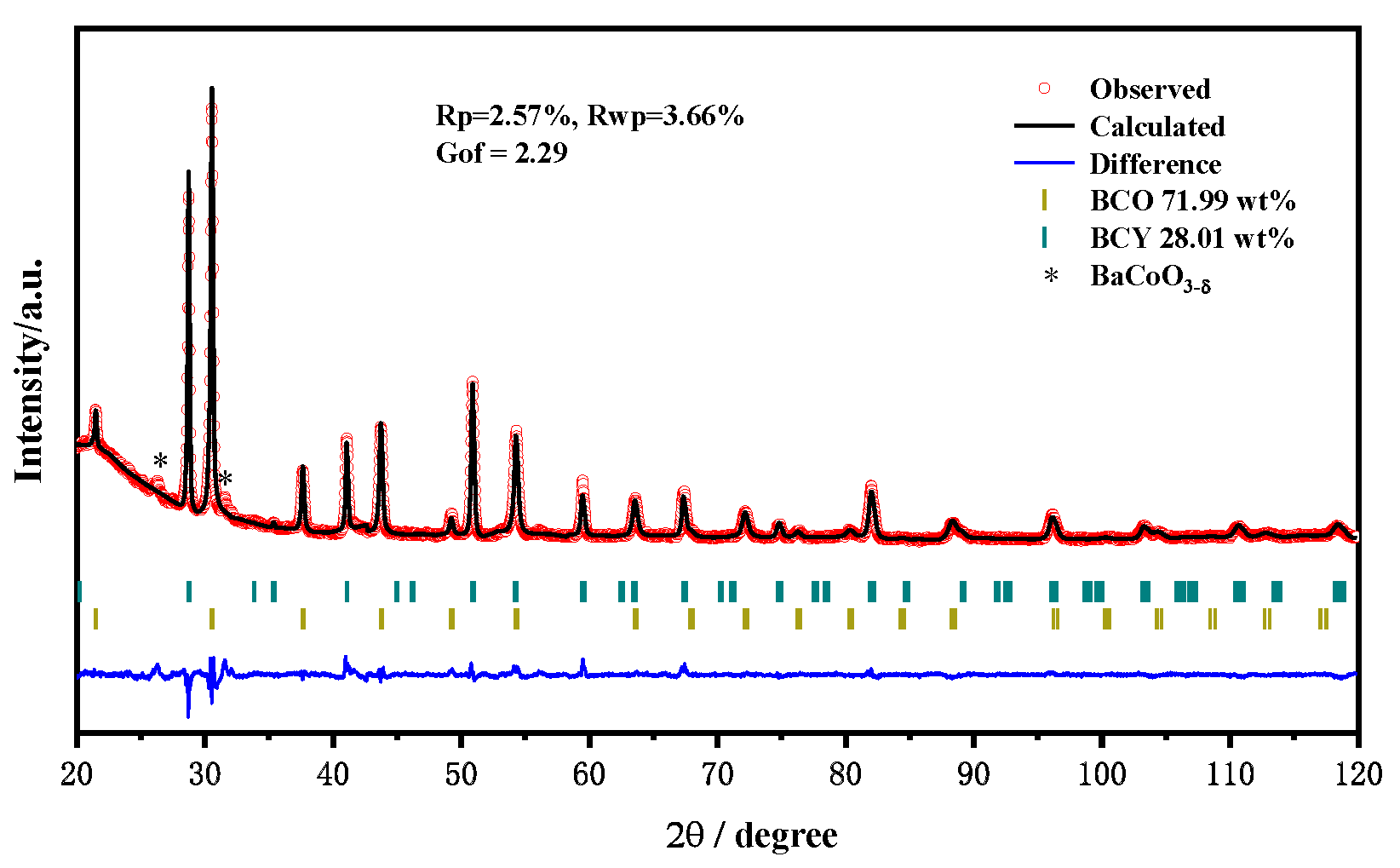
Figure 1. XRD pattern with Rietveld refinement analysis of the BCCY powder.
Nanomaterials 11 02365 g001
Figure 2. HT-XRD patterns of the BCCY sample from 400 to 550 °C.
Nanomaterials 11 02365 g002
Figure 3. XRD patterns of BCCY-4CeO2 after the heat treatment of the sample under (a) air and (b) H2 atmosphere, respectively.
Nanomaterials 11 02365 g003
Figure 4. (a) Cross-sectional SEM morphology of the BCCY-4CeO2 cell after performance test, (bd) the corresponding elemental mapping results for O, Ce and Ni, respectively. (e) The magnified image of the BCCY-4CeO2 surface.
Nanomaterials 11 02365 g004
Figure 5. The electrochemical performances for fuel cells using BCCY-CeO2 composite with different mass ratios at 550 °C.
Nanomaterials 11 02365 g005
Figure 6. (a,b) The UPS and (c,d) the UV vis-diffused reflection spectra of BCCY and CeO2.
Nanomaterials 11 02365 g006
Figure 7. The energy band structure and alignment diagram at the interface of CeO2 and BCCY particles.
Nanomaterials 11 02365 g007
Figure 8. Schematic illustration for the fuel cell using BCCY-CeO2 composite as the electrolyte and proposed transport mechanism for H+ and O2− ions.
Nanomaterials 11 02365 g008
Figure 9. Electrochemical impedance spectroscopy of the fuel cell with BCCY-CeO2 composite electrolyte at 450 °C.
Nanomaterials 11 02365 g009
Table 1. The refined phase composition and the calculated lattice parameters of BCCY.
Phasea (Å)b (Å)c (Å)Volume (Å3)
BaCe0.78Y0.22O3-δ6.21239 (14)6.21239 (14)15.2452 (7)509.543 (3)
BaCo0.9Ce0.01Y0.09O3-δ4.13906 (4)4.13906 (4)4.13906 (4)70.9096 (13)
Publisher’s Note: MDPI stays neutral with regard to jurisdictional claims in published maps and institutional affiliations.

