Abstract
Metal–organic frameworks (MOFs)-derived materials with a large specific surface area and rich pore structures are favorable for catalytic performance. In this work, MOFs are successfully prepared. Through pyrolysis of MOFs under nitrogen gas, zinc-based catalysts with different active sites for acetylene acetoxylation are obtained. The influence of the oxygen atom, nitrogen atom, and coexistence of oxygen and nitrogen atoms on the structure and catalytic performance of MOFs-derived catalysts was investigated. According to the results, the catalysts with different catalytic activity are Zn-O-C (33%), Zn-O/N-C (27%), and Zn-N-C (12%). From the measurements of X-ray photoelectron spectroscopy (XPS), it can be confirmed that the formation of different active sites affects the electron cloud density of zinc. The electron cloud density of zinc affects the ability to attract CH3COOH, which makes catalysts different in terms of catalytic activity.
1. Introduction
Vinyl acetate (VAc) is a significant chemical raw material globally, which is a colorless and flammable liquid with a sweet ether taste. VAc is mainly used to produce polyvinyl acetate (PVAc), polyvinyl alcohol (PVA), vinyl acetate-ethylene copolymer emulsion (VAE), ethylene-vinyl acetate resin (EVA), and other necessary downstream chemical raw materials, and it has also been widely used in coatings, adhesives, vinylon, and other fields [1,2,3]. At present, vinyl acetate is manufactured from petroleum ethylene and calcium carbide acetylene [4]. Given the fact that China features a coal-rich, oil-poor, and low-gas energy structure [5,6], calcium carbide acetylene is the primary source to produce vinyl acetate.
After continuous exploration and research by predecessors, it is found that the catalyst prepared with zinc as the active component and activated carbon as the carrier shows better catalytic performance in the production of vinyl acetate by the acetylene method [7,8,9]. Although it has been used in industry, there are still many shortcomings, such as a low conversion rate, easy agglomeration, deactivation of active components, and carbon deposition on catalysts. To deal with these problems, He et al. improved the activity and stability of the catalyst by doping bimetallic Zn-Ni [10] and Zn-Co [11]. Some researchers prepared V2O5-ZnO and Fe2O3-ZnO composite catalysts to extend the service life of the catalyst, but the results were not satisfactory [12,13]. There were also researchers who used nitrogen [14], oxygen [15], and boron [16] to modify activated carbon for changing the electron cloud density around zinc by changing the defect degree of the carrier, and then improving the reaction activity of the catalysts. It has been proven that many functional groups exist on the activated carbon support. However, little is known about how they affect the catalyst performance. Many scholars hold different views [15,17], rather than a uniform conclusion.
MOFs are crystalline nanoporous materials with a framework structure composed of transition metal ions and organic ligands [18], with the metal components dispersed one by one through organic ligands. On account of the large specific surface area, abundant pore structure, and surface defects of MOFs, MOFs have become a research hotspot in the fields of gas storage, gas adsorption, separation, sensors, drug controllable release, and catalytic reactions [19,20,21,22,23,24,25]. Because of their excellent chemical and thermal stability, MOFs are also used as a template or precursor for the preparation of porous carbon materials or metal composite materials [26]. By changing the types of organic ligands, catalysts doped with different elements can be prepared by simple calcination. Herein, we speculate that MOFs-derived materials can be used for catalyzing acetylene acetoxylation.
At present, the relationship between the active component and the carrier during the reaction process is not clear. This study mainly used MOFs as precursors of catalysts, after calcination under inert atmosphere; Zn-O-C, Zn-O/N-C, and Zn-N-C catalysts with different active sites were obtained, respectively; and the influence of different zinc coordination modes on the reaction was investigated.
2. Materials and Methods
2.1. Materials
Zinc nitrate hexahydrate (Zn(NO3)2·6H2O, 99.0%), terephthalic acid (H2BTC, 99.0%), N,N-dimethylformamide (DMF, 99.0%), dimethylimidazole (2-MI, 98.0%), methanol (99.5%), triethylenediamine (TEDA, 99.0%), and pyridine (PD, 99.5%), all reagents, were of analytical grade; no further purification was required.
2.2. Catalysts’ Preparation
2.2.1. Preparation of Zn-O-C Catalyst Using MOF5 Precursor
MOF5 was prepared according to the method reported in the literature [27]. First, 2.23 g of Zn(NO3)2·6H2O and 0.67 g of H2BDC were dissolved in 100 mL DMF solution, respectively; after the raw materials had dissolved entirely, the solution containing Zn(NO3)2·6H2O was slowly poured into the solution containing H2BTC. After the mixing, the solution was transparent and then underwent centrifugal collection at a speed of 800 r/min, then the solutions were poured into a 200 mL poly tetra fluoroethylene (PTFE) hydrothermal reactor autoclave and kept at 140 °C for 24 h. After cooling to room temperature, the solution was centrifuged at 8000 r/min and washed by DMF three times. To remove the unreacted solvent molecules, the sample was treated with ethanol overnight, and then dried at 80 °C to obtain the MOF5 precursor.
Secondly, the prepared MOF5 was calcined at 450 °C for 4 h with a heating rate of 5 °C/min in a tube furnace under the nitrogen atmosphere. Then, the required catalyst could be obtained by natural cooling to room temperature and was named Zn-O-C.
2.2.2. Preparation of Zn-O/N-C Catalyst Using TEDA-PD Precursor
The preparation method was based on the synthesis of Ni-MOF [28]. The preparation details are as follows: 2.38 g Zn(NO3)2·6H2O was dispersed in 100 mL DMF solution, and 1.33 g H2BTC and 0.6 g TEDA were dispersed in 100 mL DMF solution, after the complete dissolution, and the Zn(NO3)2·6H2O solution was slowly poured into the solution containing H2BDC and TEDA, and then stirred for 15 min. Next, a certain amount of PD slowly poured, and then stirred for 12 h in an oil bath at 100 °C. When it was cooled down to room temperature, the precipitate was collected by centrifugation and washed with DMF solvent three times, and subsequently it was dried under vacuum at 80 °C for 10 h; the precursor was obtained and named TEDA-PD. The catalyst obtained after 450 °C calcination was named Zn-O/N-C.
2.2.3. Preparation of Zn-N-C Catalyst Using 2-Methylimidazole Zinc Salt (ZIF8) Precursor
ZIF8 was prepared by the method reported in the literature [29]. Here, 2.23 g and 2.46 g of Zn(NO3)2·6H2O and 2-MI, respectively, were added into 40 mL methanol solution; when they were completely dissolved, the Zn(NO3)2·6H2O solution was slowly poured into the 2-MI solution, and then stirred for 24 h at 500 r/min. The precipitate was collected by centrifugation at a speed of 10,000 r/min, washed with methanol three times, and then dried in a vacuum drying oven at 80 °C for 12 h. Finally, the sample was ground to a powder to obtain ZIF8. The catalyst obtained after 550 °C calcination was named Zn-N-C.
2.3. Catalysts Characterization
The scanning electron microscope (SEM, JEOL, JSM-6490LV, Tokyo, Japan) instrument was used to image the material. The Fourier transform infrared (FT-IR, Thermo Scientific, Nicolet IS10, Waltham, MA, USA) spectra was used to identify chemical species. The specific surface area, pore volume, and pore size of the sample were recorded by an automatic fast physical adsorption analyzer (BET, Micromeritics, ASAP 2460, GA, USA), degased at 150 °C for 5 h, and then analyzed under liquid nitrogen at −196 °C to test. X-ray photoelectron spectroscopy (XPS, Thermo Fisher Scientific, ESCAlAB 250Xi, Waltham, MA, USA) was used to analyze the chemical states of elements. The thermogravimetric (TG, NETZSCH, STA 449F3, Selb, Germany) was used to test the thermal stability of the samples. The temperature-programmed desorption (TPD, Micromeritics, ASAP 2720, Norcross, GA, USA) experiment was used to determine the gas adsorption capacity and adsorption strength of the catalysts. Inductively coupled plasma mass spectrometry (ICP, Agilent, ICPOES730, Santa Clara, CA, USA) was used to test the zinc content of the samples, which used argon as the carrier gas.
2.4. Catalyst Evaluation
A self-assembled fixed-bed reaction device was used for the activity test. A stainless steel pipe with an inner diameter of 10 mm was filled with quartz sand and quartz wool at the bottom of the reaction tube for paving, and a certain amount of catalyst was added. Reaction conditions: heating temperature was set at 220 °C, the gas hourly space velocity of C2H2 (GHSV) was 500 h−1 and the molar ratio of C2H2/CH3COOH was 1:2.45. Before the reaction started, CH3COOH was used to activate the catalysts for 0.5 h, and C2H2 was introduced to start the reaction. Then, samples were taken every 1 h, using GC-9A (Shimadzu, Tokyo, Japan) gas chromatography to analyze the content of the obtained product, and the chromatographic column model was a PEG/20000 (Zhonghuida, Dalian, China) packed column.
3. Results and Discussion
3.1. Catalytic Performance Evaluation
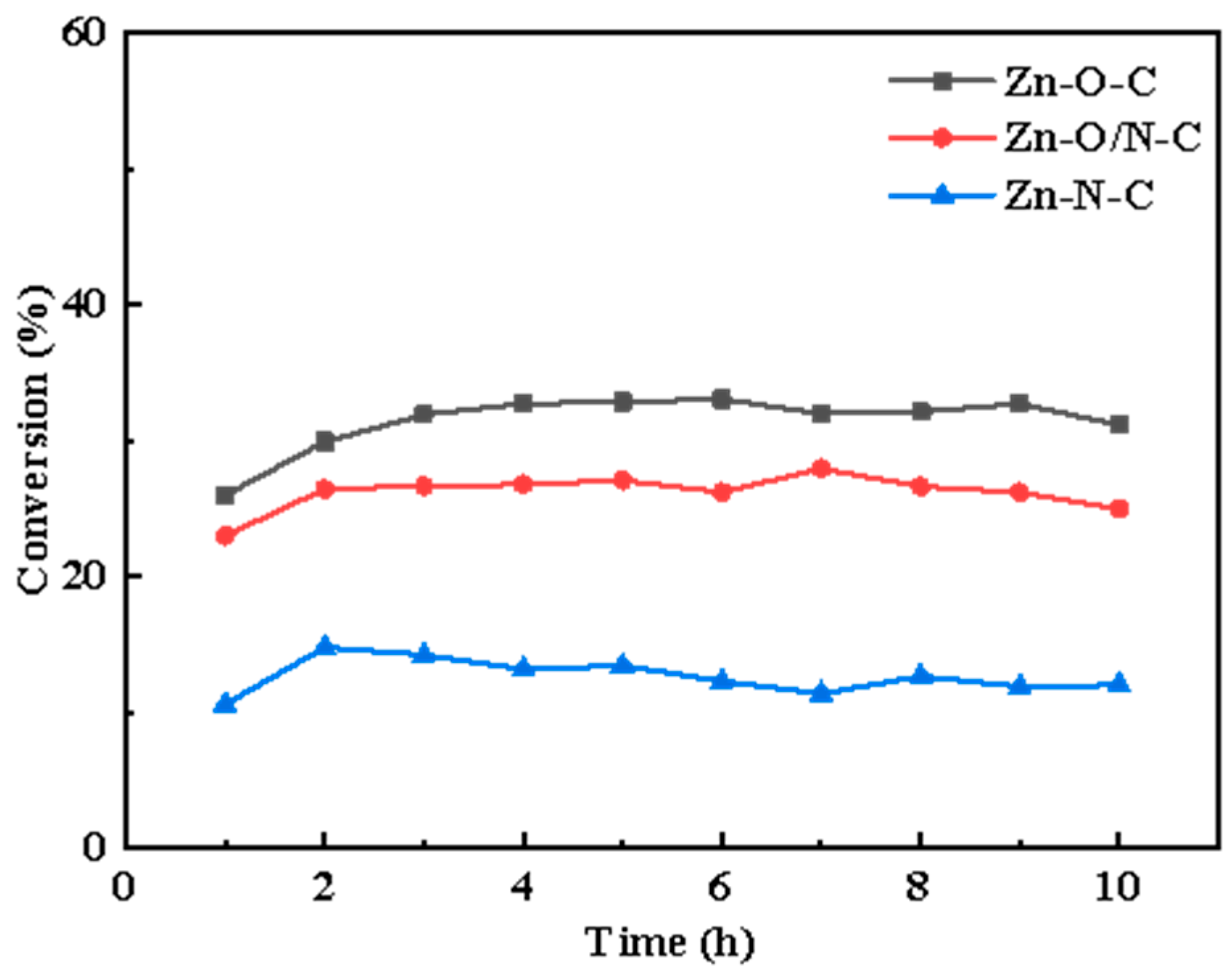
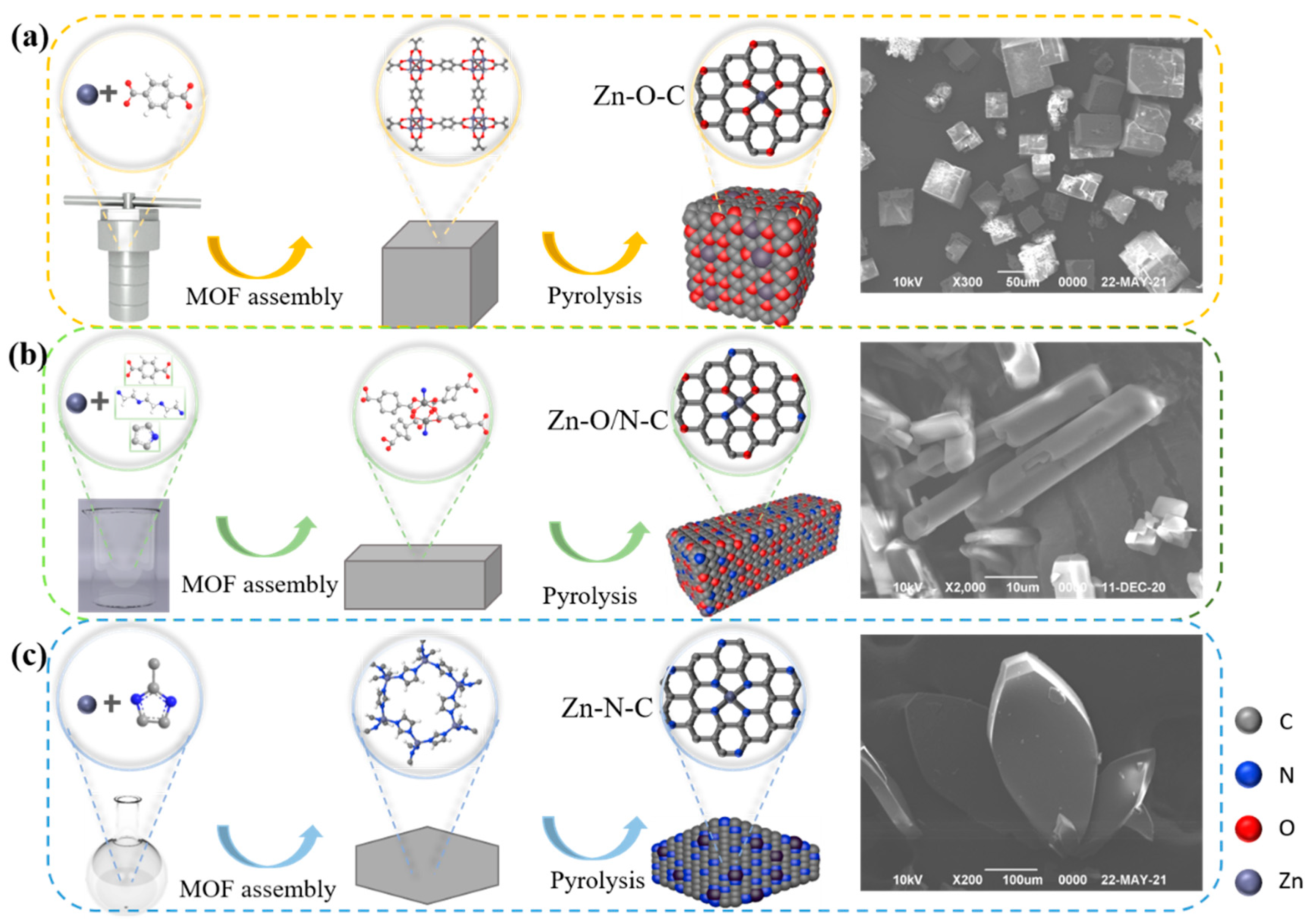
Different active sites modes can be formed by doping different organic ligands. In this study, nine kinds of zinc-based MOF materials were prepared using organic ligands, including the following: 2-MI, H2BDC, H2BDC(NH2), H2BDC(NO2), TEDA, TETA (triethylenetetramine), and PD. The microscopic morphologies of eight kinds of materials are shown in Figure S1, and it can be observed that different structures such as petal-like, cube, cuboid, and sheet-like structures, respectively, were formed with the addition of different organic ligands. In a humid environment, water molecules will replace the organic ligands in MOFs, thereby destroying the crystal structure [30]; to remove the excess H2BDC, the organic matter in the precursor was volatilized and transformed into a loose porous structure, so we calcined MOFs to prepare catalysts. The conversion rate curves are shown in Figure S2, and it can be found that there is a certain difference in catalysts’ conversion. On this basis, we selected three kinds of materials with different zinc coordination modes, reactivity (Figure 1) and similar specific surface area (Table S1) to prepare Zn-O-C, Zn-O/N-C, and Zn-N-C catalysts with three-dimensional structures using MOF5, TEDA-PD, and ZIF8, respectively, as precursors.
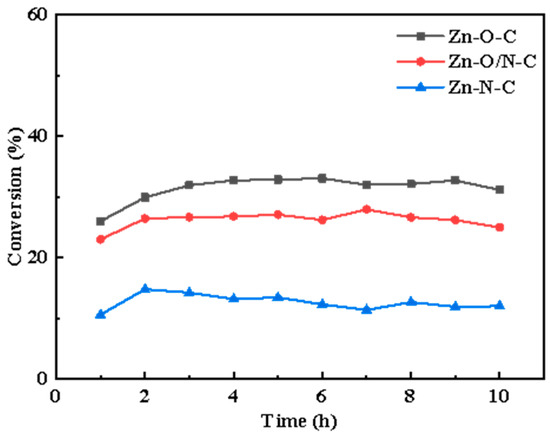
Figure 1.
The conversion rate curves of Zn-O-C, Zn-O/N-C, and Zn-N-C catalysts over time, respectively.
MOF5 is one of the typical MOFs materials, and it uses zinc as the central metal and H2BDC as the organic ligand. First, four zinc atoms and an oxygen atom from H2BDC are connected to form the secondary structural unit Zn4O(BDC)3 [31] (Figure 2a); this second structural unit is in the shape of an octahedron, and metal ions are wrapped inside as the frame nodes. Because of its strong interaction force, the entire frame structure is more stable, and Zn4O(BDC)3 is connected with the ligand to form a three-dimensional skeleton with micropores. By adding other organic ligands, such as TEDA and PD, the coordination form of zinc can be changed into Zn-N and Zn-O, named as TEDA-PD. As shown in Figure 2b, TEDA-PD consists of a pair of zinc ions connected with oxygen atoms from four H2BTC in the horizontal direction and nitrogen atoms from TEDA in the vertical direction; the vertical connection was terminated using PD as an inhibitor and the thickness of the three-position frame can be controlled by adjusting the amount of PD added. In another case, in Figure 2c, ZIF8 possesses a zeolite imidazole ester skeleton structure, as an important type of MOFs materials; zinc acts as the central metal, while 2-MI acts as the organic ligand. Zinc is connected to four nitrogen atoms from 2-MI to form a three-dimensional cage structure. Both oxygen and nitrogen atoms have relatively strong electronegativity and, when they are coordinated with zinc, they will attract electrons around zinc. As different zinc coordination shows variation in the electron cloud density around zinc, this would affect the ability of the catalysts to attract CH3COOH, and finally lead to a different activity in the catalytic reaction.
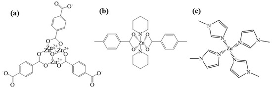
Figure 2.
Schematic diagram of chemical structures for MOF5 (a), TEDA-PD (b), and ZIF8 (c).
Figure 3a–c shows the synthesis processes. The catalytic activity sequence is Zn-O-C (33%), Zn-O/N-C (27%), and Zn-N-C (12%); Zn-O-C shows better catalytic activity, and related characterizations are analyzed in the following section to explore the mechanisms for the different activities.
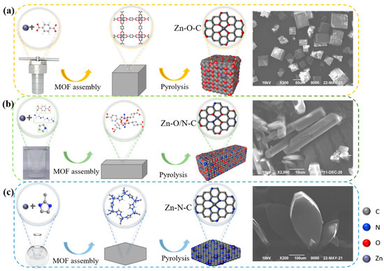
Figure 3.
Schematic diagrams of the synthesis process and the SEM images of MOF5 (a), TEDA-PD (b), and ZIF8 (c), respectively.
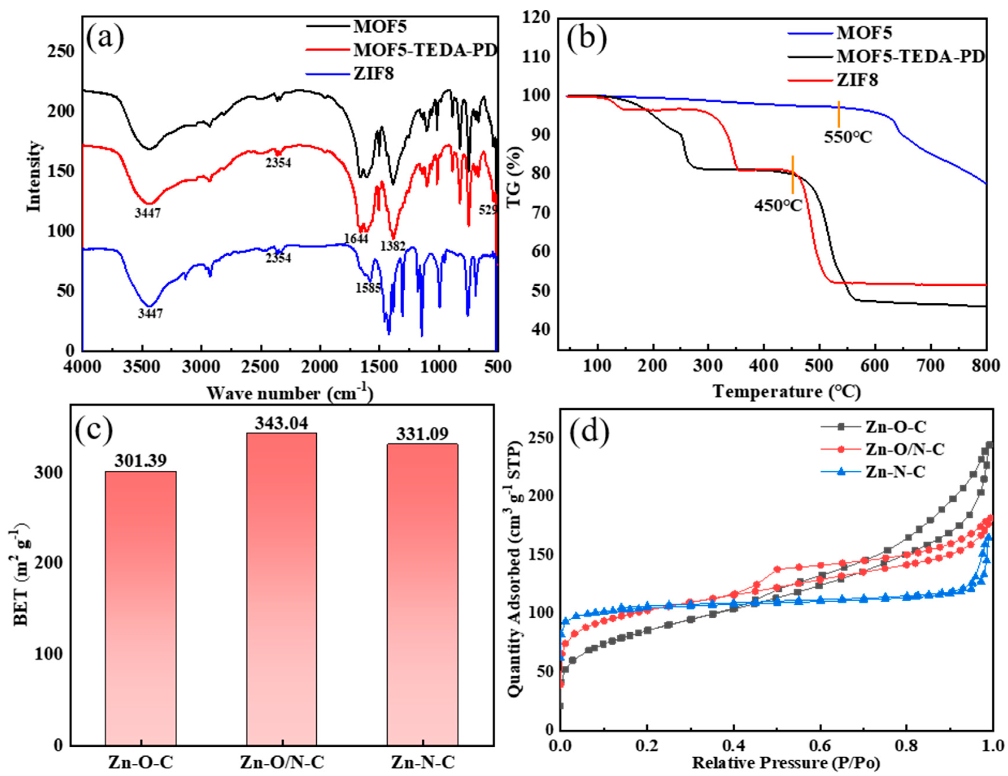
The infrared spectra of MOF5 and ZIF8 in Figure 4a are consistent with that of the reported literature [32,33], indicating that MOF5 and ZIF8 were successfully prepared. Among them, the absorption peak at 3447 cm−1 belongs to the O-H vibration, which was caused by physical adsorption of moisture in the atmosphere. The two sharp peaks around 2354 cm−1 can be attributed to C=O vibration, which came from the absorption of CO2 in the atmosphere. The peaks at 1644 cm−1 and 1382 cm−1 in MOF5 can be assigned to the symmetrical and asymmetrical stretching vibrations of O-C=O bond of the carboxyl group in H2BDC. The absorption peak of Zn-O bond in Zn4O tetrahedron is located at 529 cm−1. For the stretching vibration of the C=N bond at 1585 cm−1 in ZIF8, the band in the range of 500–1500 cm−1 is mainly caused by the bending vibration and stretching vibration in the imidazole ring.
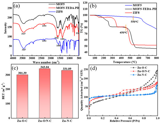
Figure 4.
FT-IR spectra (a) and TG spectra (b) of MOF5, TEDA-PD, and ZIF8. Specific surface areas (c) and adsorption and desorption curves (d) of MOF5, TEDA-PD, and ZIF8 after calcination.
According to the thermogravimetric spectra in Figure 4b, MOF5 began to collapse at about 500 °C, so 450 °C was chosen for calcination to avoid the collapse of MOFs. ZIF8 shows better thermal stability, which starts to decompose at about 600 °C; the specific surface area of the ZIF8 obtained by calcination at 450 °C was 11.77 m2/g. In comparison, ZIF8 was prepared at 550 °C to obtain similar specific surface areas to that of two other samples. MOF5, TEDA-PD, and ZIF8 were calcined to form catalysts rich in Zn-O-C, Zn-O/N-C, and Zn-N-C bonds, respectively; the BET (obtained by the Brunauer-Emmer-Teller algorithm) specific surface areas do not show much differences, with values of 301.40, 343.04, and 331.10 m2/g (Figure 4c), respectively. The adsorption and desorption curves (Figure 4d) show obvious hysteresis loops in all samples, indicating the existence of both micropores and mesopores.
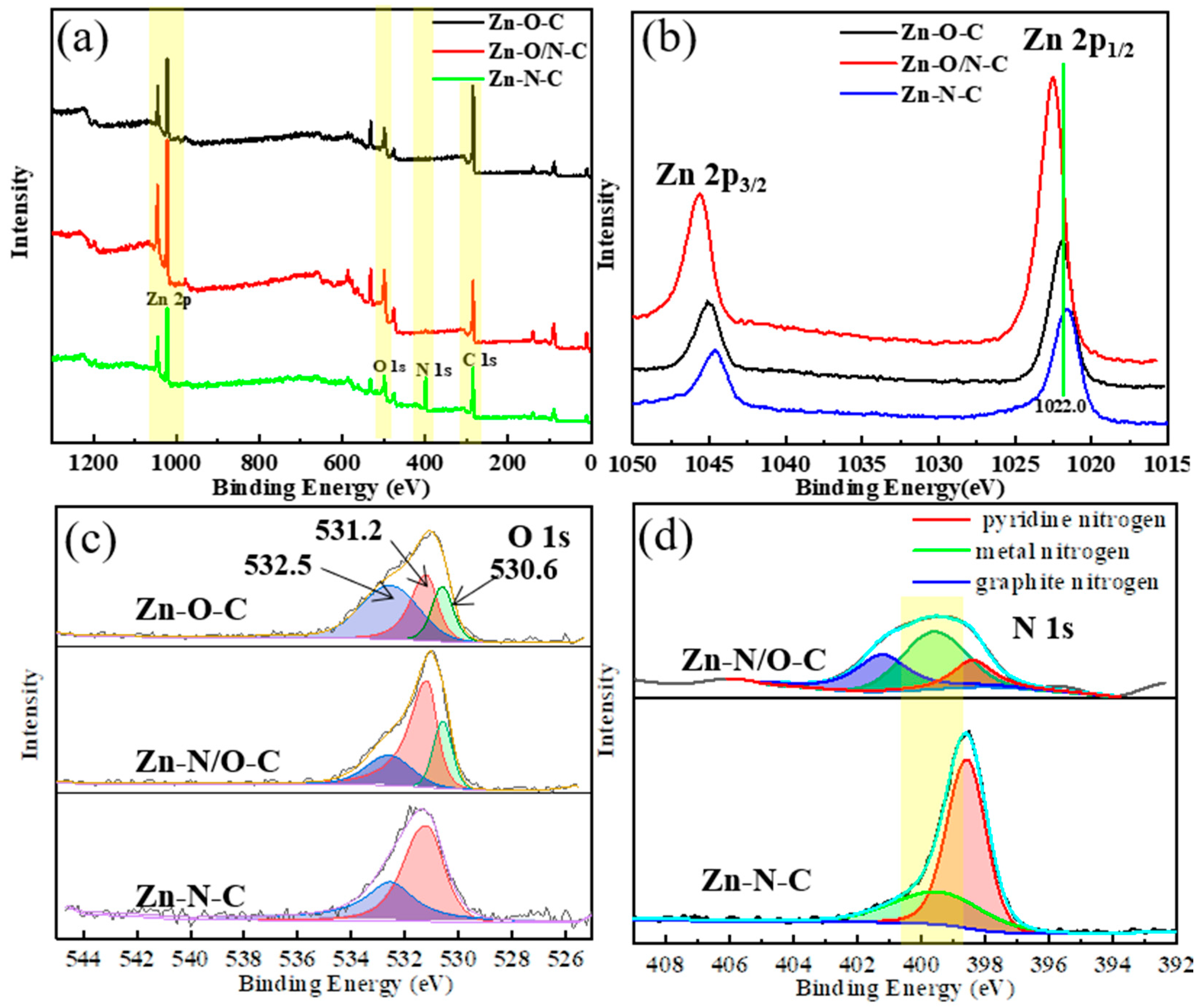
In order to further verify the different coordination forms of zinc in different catalysts, we carried out an XPS test. From the XPS spectra in Figure 5a, it can be seen that the three materials all contain zinc, oxygen, and carbon. It is difficult to observe the presence of nitrogen in Zn-O/N-C, implying that Zn-O/N-C mainly consists of Zn-O-based coordination as well as a few Zn-N bonds; the element contents of each catalyst are shown in Figure S3a. Figure 5b–d displays high-resolution spectra of Zn 2p, O 1s, and N 1s of Zn-O-C, Zn-O/N-C, and Zn-N-C catalysts. In Figure 5b, the binding energies of Zn 2p1/2 and Zn 2p3/2 for Zn-O-C [34], Zn-N-C [35], and Zn-O/N-C are 1021.9 eV and 1045.0 eV, 1021.7 eV and 1044.6 eV, and 1022.0 eV and 1045.1 eV, respectively, indicating the existence of Zn2+ in the catalysts. Moreover, the values of binding energy positions for three catalysts are Zn-O/N-C > Zn-O-C > Zn-N-C, showing that the electron cloud density around zinc for Zn-O/N-C is the largest, while it is the smallest for Zn-N-C. The coordination state of the ligands around the zinc atoms is different [36], which is caused by the difference in the ability of oxygen and nitrogen atoms [37] to attract electrons. The electronegativity of oxygen atom is greater than that of nitrogen, which makes more electrons in Zn-O-C bias towards oxygen and leads to a reduction in the electron cloud density around zinc. It can be found that the binding energy position of Zn 2p moves to the high field direction. The electron cloud density around zinc of Zn-O/N-C is large, because zinc is connected to four oxygen atoms in the horizontal direction, while having more nitrogen connections in the vertical direction than Zn-O-C, so the peak for Zn 2p shifts to a higher binding energy. The shifts in the Zn 2p binding energy positions of the three catalysts indicate that zinc has different coordination modes. The O 1s pattern in Figure 5c shows that the binding energy value of Zn-O-C is the smallest. O 1s can be fitted into three peaks at 530.6 eV, 531.2 eV, and 532.5 eV. The first peak at 530.6 eV refers to the oxygen ion from the Zn-O bond in the lattice of ZnO [37], leading to zinc atoms existing in the form Zn-O [38]. The second peak at 531.2 eV is associated with the form of OH existing on the catalysts [39]. The third peak at 532.5 eV is related to the chemisorbed oxygen on the catalysts [40]. This implies that the three catalysts have different forms of oxygen presence. Compared with Figure S3b, in which C 1s is basically indistinguishable, this indicates that carbon atom does not affect the bonding of zinc. Next, the N 1s peak splitting of Zn-N-C and Zn-O/N-C catalysts is presented in Figure 5d; the N 1s peak of Zn-N-C can be fitted into two sub-peaks, located at 398.6 eV and 399.5 eV, representing pyridine nitrogen and metal nitrogen, respectively. Compared with the Zn-N-C catalyst, the nitrogen content in Zn-O/N-C is much smaller, showing that the catalyst is mainly coordinated by Zn-O bonds, and part of the metal nitrogen was replaced by graphite nitrogen (400.9 eV) [41], so the content of metal nitrogen reduced accordingly.
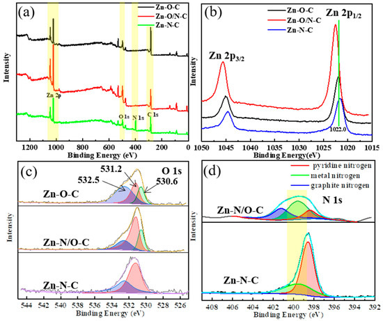
Figure 5.
XPS pattern (a) and high-resolution XPS spectra of Zn 2p (b), O 1s (c), and N 1s (d) of Zn-O-C, Zn-O/N-C, and Zn-N-C.
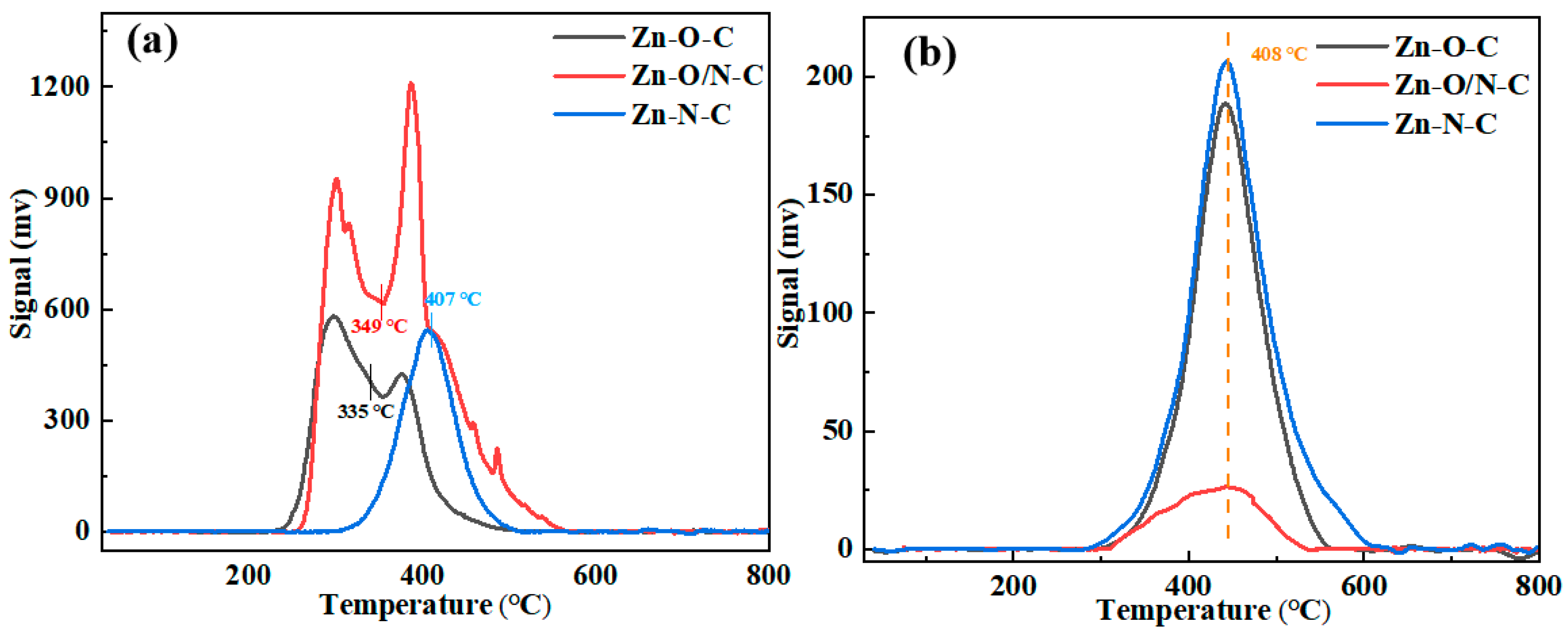
Then, the TPD tests of Zn-O-C, Zn-O/N-C, and Zn-N-C were carried out to observe the adsorption characteristics of the catalysts to the reactants, as shown in Figure 6. The area of the desorption peak represents the adsorption capacity of the reactant, and the desorption temperature indicates the adsorption strength of the reactant. It can be seen that peak temperatures of the catalysts for C2H2 are basically the same, proving that there is no difference in their adsorption strength for C2H2. The off-peak areas of Zn-O-C and Zn-N-C are mostly the same, while the off-peak area of Zn-O/N-C is the smallest. Although Zn-O/N-C has the smallest adsorption of C2H2, the catalytic activity is not very different from Zn-O-C, which shows that the adsorption amount of C2H2 has little effect on the catalytic activity of the catalysts. The de-peaking temperatures of Zn-O-C, Zn-O/N-C, and Zn-O-C for the catalysts are 335, 349, and 407 °C, respectively, indicating that the Zn-N-C catalyst needs a higher temperature to desorb CH3COOH. Comparing the off-peak area, Zn-O/N-C > Zn-O-C > Zn-N-C, it shows that Zn-O/N-C has the largest adsorption capacity for CH3COOH, while Zn-N-C has the smallest adsorption capacity for CH3COOH; the smaller electron cloud density leads to easier attraction of CH3COOH, which corresponds to the position of the Zn 2p binding energy in the XPS characterization [42].
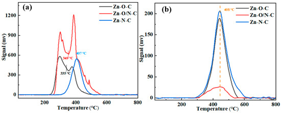
Figure 6.
TPD analysis of Zn-O-C, Zn-O/N-C, and Zn-N-C: (a) CH3COOH and (b) C2H2.
3.2. Performance of Catalysts for Acetylene Acetoxylation
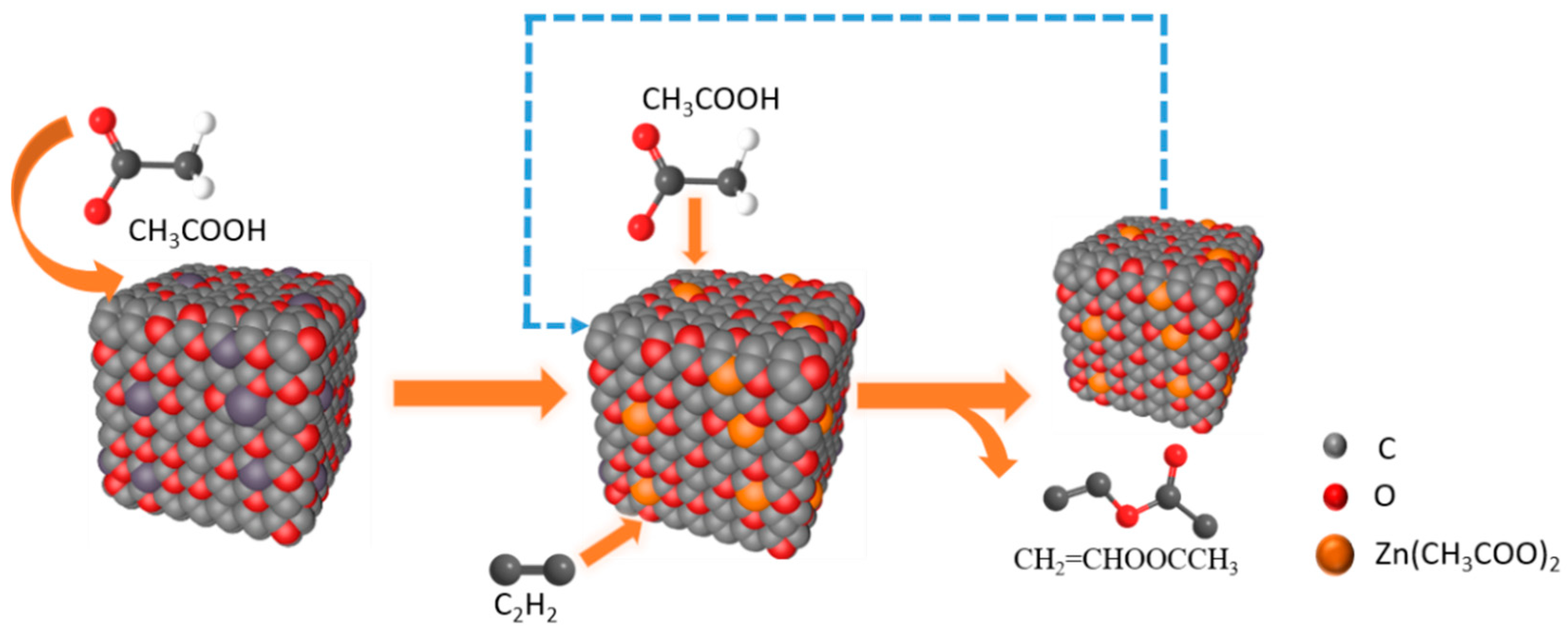
At present, there are four mechanisms of catalyzing acetylene acetoxylation, including C2H2 first absorbed by the catalyst adsorption mechanism, CH3COOH first absorbed by the catalyst adsorption mechanism, the acid catalysis mechanism, and the carbonyl promotion mechanism [3]. According to our experiments, we have found that passing C2H2 in the reaction will deactivate the catalyst. Therefore, we prefer CH3COOH first absorbed by the catalyst; the reaction process is shown in Figure 7. First, the active component is combined with CH3COOH molecules to form zinc acetate (Figure S4 demonstrates the chemical state of zinc), then C2H2 molecules are adsorbed for reaction and, finally, CH3COOCHCH2 is generated after the reaction.

Figure 7.
Reaction flow diagram taking Zn-O-C as an example.
According to the previous analysis, the main factor affecting their activity is the coordination mode of zinc. When the Zn-N bond exists, the electron cloud density around zinc is stronger, which can be proved by the position shift of XPS Zn 2p (Zn 2p binding energy position Zn-N < Zn-O). The increase in the electron cloud density around zinc weakens the attraction for CH3COOH molecules, so it is difficult to achieve better catalytic activity. At the same time, it can be found from the TPD spectra that the presence of Zn-N bonds strengthens the binding force of the catalyst and CH3COOH. When CH3COOH molecules are adsorbed on both sides of the active component at the same time, it is difficult to desorb, which hinders the subsequent reaction. From the TPD diagram of Figure S5, it can be found that Zn-N-C has a larger adsorption capacity for CH3COOCHCH2 than that of Zn-O-C, which further proves that CH3COOH on the Zn-N-C catalyst is difficult to desorb, and it can be inferred that the difficult desorption of CH3COOH is the reason for the low activity of the Zn-N-C catalyst.
4. Conclusions
In summary, MOFs precursors of MOF5, TEDA-PD, and ZIF8 were prepared by the addition of different organic ligands, resulting in different microscopic morphologies. After the calcination of MOF5, TEDA-PD, and ZIF8, the Zn-O-C, Zn-O/N-C, and Zn-N-C catalysts, respectively, were obtained with the morphologies unchanged. These catalysts were successfully used for acetylene acetoxylation, with the efficiency in the sequence of Zn-O-C (33%), Zn-O/N-C (27%), and Zn-N-C (12%). The characterization analysis revealed that the different organic ligands and the coordination environments resulted in different electron cloud densities around the active components, which further affects the CH3COOH adsorption capacity of catalysts and the catalytic reaction activity.
Supplementary Materials
The following are available online at https://www.mdpi.com/article/10.3390/nano12010098/s1, Figure S1: SEM of each substance 2-MI (a), H2BDC (b), H2BDC(NH2) (c), H2BDC(NO2) (d), H2BDC-TETA-PD (e), H2BDC-TEDA-PD (f), H2BDC-PD(5) (g), and H2BDC-PD(13) (h). (For ease of differentiation, the catalyst in this picture was named after the added ligand.), Figure S2: Reactivity of catalysts with time. (For ease of differentiation, the catalyst in this picture was named after the added ligand.), Figure S3: XPS analysis of the contents of each element (a) and C 1s (b) of Zn-O-C, Zn-O/N-C, and Zn-N-C, Figure S4: XRD patterns in each reaction stage of Zn-O-C catalyst, Figure S5: TPD analysis of Zn-O-C and Zn-N-C catalysts for CH3COOCHCH2, Table S1: Specific surface area, pore volume, and pore size data of each substance.
Author Contributions
X.W. and B.D. designed and conceived of the experiments. M.L. performed the experiments. Z.X., Y.C. and G.S. analyzed the data. X.W. and B.D. contributed reagents/materials/analysis tools. M.L. wrote the paper with direction from X.W. and B.D. All authors have read and agreed to the published version of the manuscript.
Funding
This work was financially supported by the State Key Research and Development Project of China (2016YFB03016032) and the Major Science and Technology Project of Xinjiang Bingtuan (No 2017AA007, 2020AA004).
Institutional Review Board Statement
Not applicable.
Informed Consent Statement
Not applicable.
Data Availability Statement
The data presented in this manuscript are available on request from the corresponding author.
Conflicts of Interest
The authors declare no conflict of interest.
References
- Ping, L.I.; Feng, L.R.; Jian, L.Z.; You, K.S.; Yuan, M.J.; Qiu, F.L. A Research Summary of Vinyl Acetate Synthesis from Acetic Acid and Acetylene Catalyzed by Active Carbon-zinc Acetate. Nat. Sci. J. Hainan Univ. 2006, 9, 15886. [Google Scholar] [CrossRef]
- Zhang, M.; Zhuang, J.; Wu, X.; Yu, Y. Experimental and theoretical insights into the cyclotrimerization of acetylene during vinyl acetate synthesis. Chem. Eng. J. 2019, 378, 122183. [Google Scholar] [CrossRef]
- Dong, X.; Wang, Y.; Yu, Y.; Zhang, M. Density Functional Theory Investigation on the Synthesis Mechanism of Vinyl Acetate from Acetylene and Acetic Acid Catalyzed by Ordered Mesoporous Carbon-Supported Zinc Acetate. Ind. Eng. Chem. Res. 2018, 57, 7363–7373. [Google Scholar] [CrossRef]
- Xing, B.; Wei, Z.; Wang, G. Acetate coverage effect on the reactivity of vinyl acetate synthesis on Pd/Au alloy surfaces. J. Energy Chem. 2013, 671, 600893. [Google Scholar] [CrossRef]
- Wang, Z.; Xia, C.; Xia, Y. Dynamic relationship between environmental regulation and energy consumption structure in China under spatiotemporal heterogeneity. Sci. Total Environ. 2020, 738, 140364. [Google Scholar] [CrossRef]
- Guo, X.L.; Chen, G.H.; Jian-Long, L.I. Study on Bamboo-Derived Activated Carbon as Catalyst Support for Vinyl Acetate Synthesis Using Acetic Acid and Acetylene. J. Chem. Eng. Chin. Univ. 2017, 31, 420–427. [Google Scholar] [CrossRef]
- Boehm, H.P. Some aspects of the surface chemistry of carbon blacks and other carbons. Carbon 1994, 32, 759–769. [Google Scholar] [CrossRef]
- Hoang, K.; Bong, H.; Huu, B.; Kurlyandskaya, A. Regularities of adsorption of zinc acetate from aqueous solutions onto the surface of modified activated carbons. Russ. J. Appl. Chem. 2014, 11, 104. [Google Scholar] [CrossRef]
- Zhang, Z.; Qu, W.; Peng, J.; Zhang, L.; Ma, X.; Zhang, Z.; Li, W. Comparison between microwave and conventional thermal reactivations of spent activated carbon generated from vinyl acetate synthesis. Desalination 2009, 249, 247–252. [Google Scholar] [CrossRef]
- He, P.; Wu, X.; Huang, L.; Zhu, M.; Dai, B. Acetoxylation of acetylene to vinyl acetate monomer over bimetallic Zn-Ni/AC catalysts. Catal. Commun. 2018, 112, 22. [Google Scholar] [CrossRef]
- He, P.; Huang, L.; Wu, X.; Xu, Z.; Zhu, M.; Wang, X.; Dai, B. A Novel High-Activity Zn-Co Catalyst for Acetylene Acetoxylation. Catalysts 2018, 8, 239. [Google Scholar] [CrossRef] [Green Version]
- Miyazawa, S. Metal Oxide Catalyzer for Vinyl Acetate Synthesis. J. Soc. Chem. Ind. Jpn. 1958, 61, 614–618. [Google Scholar] [CrossRef]
- Miyazawa, S. The Prevention of the Activity Decrease of Metallic Oxide Catalyst in Synthetic Process of Vinyl Acetate. J. Soc. Chem. Ind. Jpn. 1963, 66, 39–44. [Google Scholar] [CrossRef]
- He, P.; Wang, X.; Dai], B. Zinc acetate supported on N-doped activated carbon as catalysts for acetylene acetoxylation. Chem. Eng. J. 2017, 11, 1542. [Google Scholar]
- Hou, C.; Feng, L.; Li, Z.; Wang, Z.; Qiu, F. Mechanism of Carboxyl and Carbonyl Groups in Carrier Surface of Catalyst for Vinyl Acetate Synthesis. Acta Chim. Sin. Chin. Ed. 2009, 67, 1528–1532. [Google Scholar] [CrossRef]
- Zhu, F.; Zhu, M.; Kang, L. B-doped activated carbon as a support for a high-performance Zn-based catalyst in acetylene acetoxylation. Green Energy Environ. 2020, 12, 27. [Google Scholar] [CrossRef]
- Hou, C.Y.; Feng, L.R.; Qiu, F.L. Highly active catalyst for vinyl acetate synthesis by modified activated carbon. Chin. Chem. Lett. 2009, 20, 865–868. [Google Scholar] [CrossRef]
- Kitao, T.; Zhang, Y.; Kitagawa, S.; Wang, B.; Uemura, T. Hybridization of MOFs and polymers. Chem. Soc. Rev. 2017, 46, 3108. [Google Scholar] [CrossRef] [PubMed]
- Islamoglu, T.; Goswami, S.; Li, Z.; Howarth, A.J.; Farha, O.K.; Hupp, J.T. Postsynthetic Tuning of Metal–Organic Frameworks for Targeted Applications. Acc. Chem Res. 2017, 50, 805–813. [Google Scholar] [CrossRef]
- Sule, R.; Mishra, A.K.; Nkambule, T.T. Recent advancement in consolidation of MOFs as absorbents for hydrogen storage. Int. J. Energy Res. 2021, 12, 6608. [Google Scholar] [CrossRef]
- Gu, C.; Yu, Z.; Liu, J.; Sholl, D.S. Construction of an Anion-Pillared MOF Database and the Screening of MOFs Suitable for Xe/Kr Separation. ACS Appl. Mater. Interfaces 2021, 13, 11039–11049. [Google Scholar] [CrossRef]
- Thakur, B.; Karve, V.V.; Sun, D.T.; Semrau, A.L.; Weiß, L.J.K.; Grob, L.; Fischer, R.A.; Queen, W.L.; Wolfrum, B. An Investigation into the Intrinsic Peroxidase-Like Activity of Fe-MOFs and Fe-MOFs/Polymer Composites. Adv. Mater. Technol. 2021, 11, 2001048. [Google Scholar] [CrossRef]
- Yang, G.-L.; Jiang, X.-L.; Xu, H.; Zhao, B. Applications of MOFs as Luminescent Sensors for Environmental Pollutants. Small 2021, 13, 2005327. [Google Scholar] [CrossRef]
- Kampouri, S.; Ebrahim, F.M.; Fumanal, M.; Nord, M.; Schouwink, P.A.; Elzein, R.; Addou, R.; Herman, G.S.; Smit, B.; Ireland, C.P.; et al. Enhanced Visible-Light-Driven Hydrogen Production through MOF/MOF Heterojunctions. ACS Appl. Mater. Interfaces 2021, 13, 14239–14247. [Google Scholar] [CrossRef]
- He, H.; Li, R.; Yang, Z.; Chai, L.; Jin, L.; Alhassan, S.I.; Ren, L.; Wang, H.; Huang, L. Preparation of MOFs and MOFs derived materials and their catalytic application in air pollution: A review. Catal. Today 2020, 45, 33. [Google Scholar] [CrossRef]
- Sedahmed, O.; Arumugam, S.R.; Pan, J.; Wei, L. Highly activated porous carbon with 3D microspherical structure and hierarchical pores as greatly enhanced cathode material for high-performance supercapacitors. J. Power Sources 2018, 391, 162–169. [Google Scholar] [CrossRef]
- Kimitsuka, Y.; Hosono, E.; Ueno, S.; Zhou, H.; Fujihara, S. Fabrication of Porous Cubic Architecture of ZnO Using Zn-terephthalate MOFs with Characteristic Microstructures. Inorg. Chem. 2013, 52, 14028–14033. [Google Scholar] [CrossRef]
- Lin, Y.; Wan, H.; Wu, D.; Chen, G.; Zhang, N.; Liu, X.; Li, J.; Cao, Y.; Qiu, G.; Ma, R. Metal-Organic Framework Hexagonal Nanoplates: Bottom-up Synthesis, Topotactic Transformation, and Efficient Oxygen Evolution Reaction. J. Am. Chem. Soc. 2020, 142, 7317–7321. [Google Scholar] [CrossRef] [PubMed]
- Zhao, J.; Quan, X.; Chen, S.; Liu, Y.; Yu, H. Cobalt Nanoparticles Encapsulated in Porous Carbons Derived from Core–Shell ZIF67@ZIF8 as Efficient Electrocatalysts for Oxygen Evolution Reaction. ACS Appl. Mater. Interfaces 2017, 9, 28685–28694. [Google Scholar] [CrossRef] [PubMed]
- Li, M.; Huang, W.; Tang, B.; Song, F.; Lv, A.; Ling, X. Preparation of a Composite Material AC/Cu-BTC with Improved Water Stability and n-Hexane Vapor Adsorption. J. Nanomater. 2019, 2019, 5429364. [Google Scholar] [CrossRef]
- Lestari, W.W.; Wibowo, A.H.; Astuti, S.; Irwinsyah; Pamungkas, A.Z.; Krisnandi, Y.K. Fabrication of hybrid coating material of polypropylene itaconate containing MOF-5 for CO2 capture. Prog. Org. Coat. 2018, 115, 49–55. [Google Scholar] [CrossRef]
- Jiang, M.; Cao, X.; Zhu, D.; Duan, Y.; Zhang, J. Hierarchically Porous N-doped Carbon Derived from ZIF-8 Nanocomposites for Electrochemical Applications. Electrochim. Acta 2016, 196, 699–707. [Google Scholar] [CrossRef]
- Wu, Y.; Pang, H.; Yao, W.; Wang, X.; Yu, S.; Yu, Z.; Wang, X. Synthesis of rod-like metal-organic framework (MOF-5) nanomaterial for efficient removal of U(VI): Batch experiments and spectroscopy study. Sci. Bull. 2018, 63, 831–839. [Google Scholar] [CrossRef]
- Li, X.; Wang, L.; Li, X.; Zhang, J.; Wang, M.; Che, R. Multi-dimensional ZnO@MWCNTs assembly derived from MOF-5 heterojunction as highly efficient microwave absorber. Carbon 2021, 172, 15–25. [Google Scholar] [CrossRef]
- Liu, Z.; Wu, A.; Yan, H.; Su, D.; Jin, C.; Guo, H.; Wang, L.; Tian, C. An effective "precursor-transformation" route toward the high-yield synthesis of ZIF-8 tubes. Chem. Commun 2020, 56, 2913–2916. [Google Scholar] [CrossRef]
- Karakawa, M.; Sugahara, T.; Hirose, Y.; Suganuma, K.; Aso, Y. Thin Film of Amorphous Zinc Hydroxide Semiconductor for Optical Devices with an Energy-Efficient Beneficial Coating by Metal Organic Decomposition Process. Sci. Rep. 2018, 8, 10839. [Google Scholar] [CrossRef]
- Pant, A.; Tanwar, R.; Kaur, B.; Mandal, U.K. A magnetically recyclable photocatalyst with commendable dye degradation activity at ambient conditions. Sci. Rep. 2018, 8, 14700. [Google Scholar] [CrossRef] [PubMed]
- Dai, L.P.; Deng, H.; Chen, G.; Tang, C.F.; Wei, M.; Li, Y. Growth of a–b-axis orientation ZnO films with zinc vacancies by SSCVD. Vacuum 2007, 81, 969–973. [Google Scholar] [CrossRef]
- Abdalla, A.; Bereznev, S.; Spalatu, N.; Volobujeva, O.; Sleptsuk, N.; Danilson, M. Pulsed laser deposition of Zn(O,Se) layers in nitrogen background Pressure. Sci. Rep. 2019, 9, 17443. [Google Scholar] [CrossRef] [PubMed] [Green Version]
- Dupin, J.C.; Vinatier, P.; Levasseur, A. Systematic XPS Studies of Metal Oxides, Hydroxides and Peroxides. Phys. Chem. Chem. Phys. 2000, 2, 1319–1324. [Google Scholar] [CrossRef]
- Artyushkova, K. Misconceptions in interpretation of nitrogen chemistry from x-ray photoelectron spectra. J. Vac. Sci. Technol. A Vac. Surf. Film. 2020, 38, 031002. [Google Scholar] [CrossRef] [Green Version]
- Kovács, I.; Iost, N.; Solymosi, F. Thermal and photo-induced dissociation of (C2H5)2Zn to yield C2H5 on the Pd(100) surface. J. Chem. Phys. 1994, 101, 4236–4247. [Google Scholar] [CrossRef] [Green Version]

Publisher’s Note: MDPI stays neutral with regard to jurisdictional claims in published maps and institutional affiliations. |
© 2021 by the authors. Licensee MDPI, Basel, Switzerland. This article is an open access article distributed under the terms and conditions of the Creative Commons Attribution (CC BY) license (https://creativecommons.org/licenses/by/4.0/).