Abstract
This paper proposes a novel nanobar–substrate medium model for static and free vibration analyses of single-walled carbon nanotube (SWCNT) systems embedded in the elastic substrate medium. The modified strain-gradient elasticity theory is utilized to account for the material small-scale effect, while the Gurtin–Murdoch surface theory is employed to represent the surface energy effect. The Winkler foundation model is assigned to consider the interactive mechanism between the nanobar and its surrounding substrate medium. Hamilton’s principle is used to consistently derive the system governing equation, initial conditions, and classical as well as non-classical boundary conditions. Two numerical simulations are employed to demonstrate the essence of the material small-scale effect, the surface energy effect, and the surrounding substrate medium on static and free vibration responses of single-walled carbon nanotube (SWCNT)–substrate medium systems. The simulation results show that the material small-scale effect, the surface energy effect, and the interaction between the substrate and the structure led to a system-stiffness enhancement both in static and free vibration analyses.
1. Introduction
Over the last few decades, nano-sized structures have found a wide spectrum of applications in nano-sized devices due to their superior and unique mechanical properties [1,2,3,4,5], for example, nanofilms [6], nanobiosensors [7], nanomotors [8], nanoswitches [9], nano-electro-mechanical systems (NEMS) [10], nanowires [11], and atomic force microscopes (AFM) [12]. To reliably design and fabricate such tiny devices, mechanical characteristics of their small-sized structural components are utterly crucial and necessary. Generally, the most straightforward way to characterize the mechanical properties of structures is the experimental approach. Unfortunately, conducting an experiment on nano-sized structures is extremely cumbersome and requires a high-precision testing apparatus and a unique testing procedure [13,14,15]. The atomistic modeling approach based on the quantum mechanics theory could be a viable choice to characterize the mechanical properties of small-sized structures, but high computational costs and complex computational procedures inherently arise with this modeling approach [16,17,18,19,20]. Therefore, the atomistic modeling approach is valid only to systems with small numbers of molecules and atoms. To remedy the aforementioned difficulties inherent to experimental and atomistic modeling approaches, there is a pressing need for a more efficient modeling approach to characterize the mechanical properties of nano-sized structures. Such a modeling approach could be possible with unification of enhanced elasticity theories and structural mechanics models, thus leading to the so-called “enhanced” structural mechanics models. A family of enhanced structural mechanics models has been formulated by researchers worldwide and ranges from a relatively simple bar model to a sophisticated curvilinear shell model [21,22,23,24,25]. Small-scale and/or size-dependent effects have been incorporated into these enhanced structural mechanics models. The small-scale effect is induced by the long-range inter-atomic interaction, while the size-dependent effect is caused by excessive energy of atoms at the free surface.
When the structural dimension is in the order of nanometers, the discrete nature of materials becomes essential and induces the small-scale effect. In the research community, several enhanced elasticity theories have been formulated by several researchers to consider the small-scale effect, such as nonlocal elasticity theory [26,27], strain-gradient theory [28], modified strain-gradient elasticity theory [13], couple stress theory [29], and modified couple stress theory [30]. It is worth mentioning that the common feature of these enhanced elasticity theories is the supplement of material length-scale parameters to account for the small-scale effect associated with the discrete nature of materials. As the most widely used among these enhanced elasticity theories, the nonlocal elasticity theory of Eringen [26,27] has been employed to characterize the small-scale effect on static and dynamic responses of nano-sized structures for the last two decades [31,32,33,34,35,36,37,38,39]. For example, Reddy and Pang [31] developed the Euler–Bernoulli and Timoshenko beam models based on the Eringen nonlocal differential constitutive relation to study the effect of the nonlocal parameter on the bending, buckling, and natural vibration of straight beams. Wang et al. [32] investigated the transverse shear deformation within the micro- and nano-beams by using the Timoshenko beam model based on Eringen’s nonlocal elasticity theory. Juntarasaid et al. [33] extended the Euler–Bernoulli beam model of Reddy and Pang [31] to consider the surface effects for bending and buckling analysis of the nanowire. Barretta et al. [34] developed the Eringen differential law by the suggestion of an additional term involving the derivative of the axial stress. Ebrahimi and Shafiei [35] proposed a rotating, functionally graded (FG) Timoshenko nanobeam based on Eringen’s nonlocal theory to study the size-dependent vibration behavior. Limkatanyu et al. [36] employed the so-called “strain-driven” nonlocal elasticity model as proposed by Eringen [27] to enrich the Euler–Bernoulli beam model. Next, Nguyen et al. [37] studied the bending, buckling, and post-buckling of nanobeams undergoing large displacements and rotations based on the Eringen nonlocal beam model. Subsequently, Sayyad and Ghugal [38] presented a theoretical unification of twenty-one nonlocal beam theories based on Eringen’s nonlocal elasticity theory for the bending, buckling, and vibration analysis of FG nanobeams, while Lal and Dangi [39] proposed the nonlocal Timoshenko beam model for vibration analysis of bi-directional FG moderately thick nanobeams. However, skeptical and inconsistent responses could arise with the nonlocal elasticity model [40]. For example, Peddieson et al. [40] demonstrated that the beam model based on the Eringen nonlocal differential form presents no small-scale effect on the displacement response of the cantilever beam under an end load. This peculiar response was subsequently defined as a “paradox” [40,41]. It was diagnosed by Romano et al. [41] that adoption of the Eringen nonlocal differential model can result in an ill-posed structural mechanics problem (bounded domain). Furthermore, Koutsoumaris et al. [42] showed that the quadratic energy functional form of elasticity does not exist for the Eringen nonlocal differential model, and Ma et al. [43] pointed out that there is ambiguity in the conjugate stress–strain pairs in this nonlocal constitutive model. To deviate from skeptical and inconsistent features inherent to the Eringen nonlocal differential model, several researchers have paid attention to strain-gradient-type constitutive models. Within the framework of the strain-gradient-type constitutive model, there is no ambiguity in the conjugate stress–strain pairs and there exists the quadratic energy functional form of elasticity, thus leading to a rational nano-sized structural model. Among a family of strain-gradient-type constitutive models, the modified strain-gradient elasticity model proposed by Lam et al. [13] is of particular interest in the present work since strain-gradient measures associated with different deformations are naturally considered in this strain-gradient-type model, as will be pursued herein.
Besides the abovementioned small-scale effect, the size-dependent characteristic induced by the surface energy effect becomes essential when the structural dimension is in the order of nanometers. The surface energy effect is related to excessive energy stored in the bulk surface of nano-sized structures. Both atomistic modeling and experimental studies on the nano-sized structure have confirmed the existence of the surface energy effect [44,45,46]. To incorporate the surface energy effect into the structural mechanics model, several researchers have used the surface elasticity theory proposed by Gurtin and Murdoch [47,48]. The fundamental assumption of this surface theory is that the wrapping surface layer is considered as a zero-thickness, two-dimensional membrane perfectly bonded to its embracing bulk material and possessing its own elastic properties.
In nanomaterials and nanodevices, nanobars have often been assembled into larger parts through elastic substrate media [49]. Therefore, the interactive mechanism between the bar and its surrounding substrate medium is paramount to the design and control of the performance of such materials and devices during their lifetime services. Up to now, nanobar–substrate medium models available in the literature have mainly been developed for static analyses of nanobar–substrate medium systems under tensile loadings. For example, Limkatanyu et al. [50,51] developed the bar–substrate medium model based on the nonlocal elasticity theory of Eringen [26,27] to characterize axial responses of nanowire-substrate medium systems. Sae-Long et al. [52] and Limkatanyu et al. [53] unified the thermodynamic-based strain-gradient model of Barretta and Marotti de Sciarra [54] and the surface elasticity model of Gurtin and Murdoch [47,48] to develop a “paradox-free” nanobar-elastic substrate medium model. Sae-Long et al. [55] combined the four-order strain-gradient model of Narendar and Gopalakrishnan [56] with the surface elasticity model of Gurtin and Murdoch [47,48] to formulate the sixth-order bar-elastic substrate medium model containing one material length-scale parameter. Apart from the static characteristic of nanobar–substrate medium systems, their dynamic characteristic is also essential to rational design and fabrication processes of nanomaterials and nanodevices. Consequently, there is still room to add a more general mathematical model of nanobar–substrate medium systems into the research community. To the authors’ best knowledge, the present study proposes, for the first time, a combination of the modified strain-gradient elasticity model of Lam et al. [13] and the surface elasticity model of Gurtin and Murdoch [47,48] to formulate a rational nanobar–substrate medium model for static and dynamic analyses.
The content of the present study is as follows: First, the interactive mechanism between the bar and its surrounding substrate medium is presented. Then, the modified strain-gradient elasticity model of Lam et al. [13] and the surface elasticity model of Gurtin and Murdoch [47,48] are discussed. Next, Hamilton’s principle is employed to reveal the system governing equation, initial conditions, and classical as well as non-classical boundary conditions. These equations establish a complete set of the mathematical tool to perform static and free vibration analyses of the nanobar–substrate medium systems. Finally, two numerical simulations are employed to demonstrate the essence of the material small-scale effect, the surface energy effect, and the surrounding substrate medium on static and free vibration responses of single-walled carbon nanotube (SWCNT)–substrate medium systems.
2. Nanobar–Substrate Medium Interaction
In the present study, the interactive mechanism between the nanobar and its surrounding substrate medium is characterized by the Winkler foundation model [57]. Based on this foundation model, the surrounding substrate medium is considered as smeared tangential springs distributed along the nanobar length, as shown in Figure 1. The constitutive relation between the substrate interactive force, , and the substrate deformation, , is [57]:
where is the substrate medium stiffness.
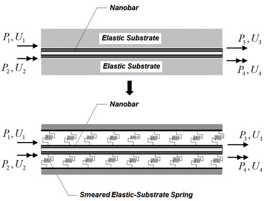
Figure 1.
Nanobar–substrate medium system.
3. Modified Strain-Gradient Theory
The modified strain-gradient theory employed herein is one of simplified variants of Mindlin’s strain-gradient theory [28,58] and was first proposed by Lam et al. [13]. To consider the material small-scale effect inherent to nano-sized structures, the strain-gradient theory asserts that the stress at a generic point is described as a function of local strain and strain gradients at that point. Consequently, the modified strain-gradient theory of Lam et al. [13] possesses three more material constants related to strain gradients in addition to two conventional material constants (Lame constants).
For a modified strain-gradient elastic body, the stored elastic strain energy, , is given by Lam et al. [13] as:
where represents the volume of the elastic body, represents the infinitesimal strain and is the conjugate–work pair of the classical stress, , , , and represent strain-gradient measures related to the dilatation gradient, the deviatoric stretch gradient, and the symmetric rotation gradient, respectively, and , , and represent the higher-order stresses and are the conjugate–work pairs of the strain-gradient measures , , and , respectively.
In the modified strain-gradient theory, the constitutive relations between stress and strain quantities are [59]:
where and are Lame constants, , , and are the material length-scale parameters related to the dilatation gradient, the deviatoric stretch gradient, and the symmetric rotation gradient, respectively, and is Kronecker delta.
The strain, , and the strain-gradient measures , , and are defined as [59]:
where is the displacement vector and is the permutation symbol.
4. Surface Elasticity Theory
As the size of a structure is in the range of nanometers, the free energy at the surface of a bulk material becomes comparable to the energy stored in the bulk material. Therefore, the size-dependent phenomenon induced by this surface-free energy is essential in characterizing the mechanical response of nano-sized structures. To incorporate this size-dependent phenomenon into the proposed nanobar–substrate medium model, the present study employs the surface elasticity theory proposed by Gurtin and Murdoch [47,48]. Based on the hypothesis of this surface elasticity model, the nanobar cross-section is assumed to consist of a solid core and its wrapping outer surface shell, as shown in Figure 2. The solid core and its wrapping outer surface shell are assumed to be in a perfect bond condition. The wrapping outer surface shell is taken as a mathematically zero-thickness elastic layer. The constitutive relation of the surface layer can be expressed as [47,48]:
where and are the surface elastic constants, is the in-plane components of the surface stress, is the residual surface stress based on the unconstrained conditions and is determined from the atomistic simulation [45], and is the surface layer deformation.
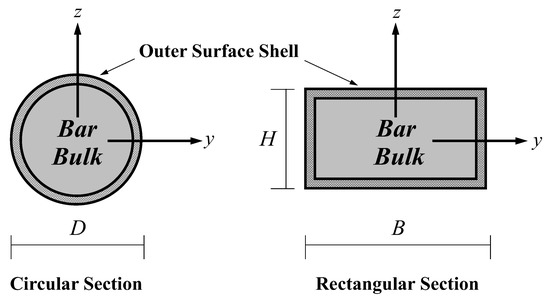
Figure 2.
Composite nanobar cross-section: bar-bulk and outer wrapping surface shell.
5. Nanobar–Substrate Medium Model: Single-Walled Carbon Nanotube (SWCNT)–Substrate Medium System
5.1. Kinematics
In the present work, a SWCNT is considered as a bar, thus focusing merely on the axial response. Therefore, only the bar axial displacement, , shown in Figure 3 is relevant. It is worth mentioning that the bar axial displacement, , is described as a function of the spatial variable and the temporal variable , since both static and free vibration responses of SWCNT–substrate medium systems are investigated in this study.
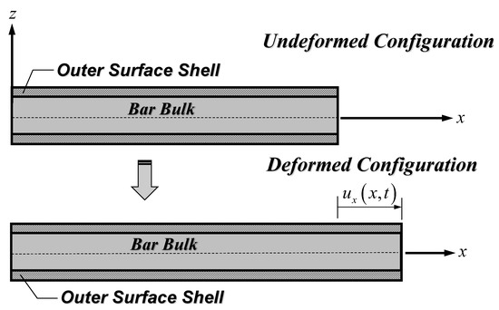
Figure 3.
Nanobar kinematical description.
Following the bar kinematics of Figure 3, the non-zero strain of Equation (7) and strain-gradient measures of Equations (8)–(10) are [59]:
It is noted that the bar kinematics of Figure 3 results in a vanishing symmetric rotation gradient, . Consequently, the higher-order stress, , also vanishes based on the constitutive relation of Equation (6), and the material length-scale parameter, , becomes unnecessary.
Employing Equations (12)–(15), the non-vanishing stress quantities (classical and higher-order stresses) of Equations (3)–(5) can be expressed in terms of the bar axial displacement, , as [59]:
with being the elastic modulus of the bar-bulk material. It is worth mentioning that the effect of Poisson’s ratio, , is neglected in the present study. This assumption was also made for the modified strain-gradient bar model proposed by Akgöz and Civalek [59].
Enforcing the full compatibility condition of the nanobar–substrate medium system (), the substrate medium constitutive relation of Equation (1) can be expressed in terms of the bar axial displacement, , as [57]:
Following the full compatibility condition of the bar-bulk-wrapping surface layer system () and the bar section kinematics, the surface layer constitutive relation of Equation (11) can be written in terms of the bar axial displacement, , as [47,48]:
where and are, respectively, the surface stress and the residual surface stress in the axial direction, is the surface elastic modulus, and is the surface layer strain.
5.2. Formulation: Hamilton’s Principle
Based on the system constitutive relations of Equations (16)–(21), the elastic strain energy, , stored in the nanobar–substrate system can be expressed in terms of the bar axial displacement, , as:
where is the nanobar sectional area, and is the nanobar sectional perimeter.
The first variation of the elastic strain energy, , of Equation (22) during the time interval [, ] is:
In order to remove all differential operations from the virtual axial displacement, , integration by parts is applied to Equation (23), thus resulting in the following expression:
where represents the higher-order axial stiffness considering the bar-bulk dilatation strain gradient and the bar-bulk deviatoric stretch strain gradient, and is the lower-order axial stiffness combining the bar-bulk and surface layer contributions.
Next, the first variation of the external work, , performed due to the axially distributed load, , and end forces, , as shown in Figure 1, during the time interval [, ] can be expressed as:
where the displacement vector collects end displacements of the system, and the force vector contains end forces of the system.
Finally, the first variation of the kinetic energy, , for the axial response during the time interval [, ] is given by Akgöz and Civalek [59] as:
where is the bar-bulk mass density.
Recalling Hamilton’s principle, the relations in Equations (24)–(26) can be written together as:
Accounting for the arbitrariness of , the governing differential equation of motion (Euler–Lagrange equation) for a nanobar–substrate medium system can be deduced from Equation (27) as:
It is worth remarking that Equation (28) becomes identical to the governing differential equation of motion for a modified strain-gradient nanobar model proposed by Akgöz and Civalek [59] when the surrounding substrate medium and the surface energy effect are neglected (). Moreover, when the effects of the material small-scale and surface energy are all neglected (), Equation (28) degenerates to the governing differential equation of motion for a bar embedded in the Winkler foundation [51].
Considering the arbitrariness of and on boundary terms in Equation (27) yields initial conditions as well as boundary conditions of the nanobar–substrate medium system as:
Initial conditions:
Boundary conditions:
5.3. Analytical Solution of the Nanobar–Substrate Medium System: Static Analysis
When the inertia force on the right-hand side is omitted, Equation (28) degenerates to the governing differential equilibrium equation of a nanobar–substrate medium system:
The general solution to the governing differential equilibrium equation of Equation (31) can be written as:
where is the homogeneous solution for , and is the particular solution and is dictated by the axially distributed load, .
It is observed that Equation (31) is in the same form as the governing differential equilibrium equation of the beam on the Winkler–Pasternak foundation [60]. Therefore, the homogeneous solution, , given by Limkatanyu et al. [60] can be employed for the present problem. There are three cases for the homogeneous solution, , to Equation (31) depending on the values of the system parameters and .
Case I:
Case II:
Case III:
with the auxiliary variables and being defined as:
where , , , and are constants of integration to be obtained by enforcing boundary conditions.
5.4. Analytical Solution of the Nanobar–Substrate Medium System: Free Vibration Analysis
To obtain the analytical solution to the governing differential equation of motion of Equation (28), the method of separation of variables is utilized. Therefore, the axial displacement, , can be expressed as [59]:
where represents the natural frequency of the nanobar–substrate medium system.
Substituting Equation (38) into Equation (28) and setting and to be zero for the free vibration analysis leads to the following equation for the non-trivial solution :
where and represent the auxiliary parameters.
As suggested by Dinçkal et al. [61], there are two possible solution cases for the non-trivial solution, :
Case I:
with
Case II:
with
6. Numerical Simulations
To assess both static and free vibration characteristics of SWCNT–substrate medium systems, this study employs the proposed nanobar–substrate medium model to analyze SWCNT–substrate medium systems through two numerical simulations. Each simulation contains two analysis cases and will be presented in the following sections.
6.1. Simulation I: Static Analysis
Simulation I investigates static responses of nanobar–substrate medium systems with two analysis cases. The first one considers only the material small-scale effect and demonstrates the ability of the proposed model to eliminate the paradoxical response inherent to the widely used small-scale bar model, while the second one assesses the influences of system parameters on the effective Young’s modulus of the nanobar–substrate system.
6.1.1. Paradox Resolved
Several small-scale bar models available in the literature have shown no small-scale effect under a constant axial-force state, and this peculiar behavior has been considered as a paradox [62]. Therefore, the present analysis case is employed to show the ability of the proposed model to eliminate this paradoxical response.
Figure 4 shows a cantilever SWCNT subjected to an end load = 100 nN, thus inducing a constant axial-force state. As stated by Jena et al. [63], the bulk modulus, , of the SWCNT is 1 TPa. The following geometric properties of the SWCNT follow those employed by Jena et al. [63]: length, , of 10 nm, diameter, , of 2.17 nm, and wall thickness, , of 0.34 nm. To consider only the material small-scale effect, model parameters associated with the surface energy effect and the surrounding substrate medium are set to be zero (). The material length-scale parameters associated with the dilation gradient, , and the deviatoric stretch gradient, , are set to be identical () and vary from 0.5 to 2 nm. Three bar models based on different constitutive relations are used in this analysis case, namely: the proposed bar model, the local (classical) bar model, and the Eringen nonlocal bar model of Limkatanyu et al. [50]. As suggested by Akgöz and Civalek [59], imposed classical and non-classical boundary conditions for the cantilever SWCNT are:
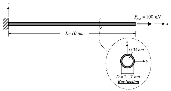
Figure 4.
Cantilever SWCNT subjected to a constant axial-force state: static analysis.
Figure 5 presents and compares the axial-displacement distributions obtained with all three bar models. Clearly, the axial-displacement response obtained with the Eringen nonlocal bar model is identical to that obtained with the local bar model. Therefore, the Eringen nonlocal differential model fails to represent the material small-scale effect under the constant axial-force state. Contrastingly, the modified strain-gradient bar model proposed herein succeeds in capturing the material small-scale effect and yields a stiffer axial-displacement response when compared to that obtained with the local bar model. This increased system stiffness complies well with experimental evidence and analytical results available in the literature [13,64,65].
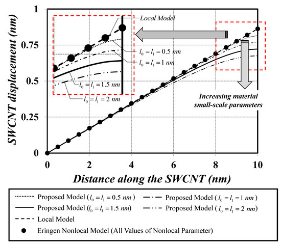
Figure 5.
Axial displacement versus distance along the cantilever SWCNT under a constant axial-force state.
6.1.2. Parametric Investigation of System Parameters on the Effective Young’s Modulus
Influences of several system parameters on the effective Young’s modulus, , are scrutinized in the present analysis case. A free–free SWCNT embedded in elastic substrate medium under an end load = 100 nN, as shown in Figure 6, is employed in this parametric investigation. The material and geometric properties of the SWCNT follow those employed in the previous analysis case. The surface property of the SWCNT is given by Jena et al. [63]. The elastic surface modulus, , is 35.3 nN/nm, while the residual surface stress is assumed to be zero (). The material length-scale parameter associated with the deviatoric stretch gradient, , is kept constant at 1 nm. System parameters assessed in this analysis case are the dilation-gradient small-scale parameter, , the SWCNT diameter, , and the elastic substrate stiffness, . The material length-scale ratio, , varies from 0 to 4. The slenderness ratio, , ranging from 10 to 50 is employed to specify the SWCNT diameter parameter, thus reflecting the surface energy effect. A specified value of the slenderness ratio, , can be obtained by keeping = 10 nm and varying . The corresponding wall thickness, , of the SWCNT is equal to , thus keeping the ratio constant at 3.44. This specific value of is given by Anvari [66]. The dimensionless substrate-stiffness parameter, , ranging from 1 to 100 is employed to vary the elastic substrate stiffness, , and is defined as [50]:
where represents a stiffness coefficient of the substrate medium and is defined as . This range of the dimensionless substrate-stiffness parameter, , follows that employed by Demir et al. [67].
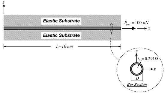
Figure 6.
Free–free SWCNT–substrate medium system under an end force: static analysis.
Classical and non-classical boundary conditions for the free–free SWCNT–substrate system follow those suggested by Akgöz and Civalek [59]:
Employing the procedure suggested by He and Lilley [68], the effective Young’s modulus, , can be obtained in the following fashion: The end displacement, , of the SWCNT–substrate medium system is first computed using the proposed model. Subsequently, Equation (50) is solved for .
It is noted that the right-hand side of Equation (50) defines the end displacement analytically obtained from the local bar–substrate medium system.
The variation of the effective Young’s modulus, , with all above-mentioned system parameters is shown Figure 7. It is worth mentioning that solution case I () of Equation (33) and solution case II () of Equation (34) are both activated in the present analysis case. Figure 7 shows that the effective Young’s modulus, , nonlinearly increases with increasing the dilation-gradient small-scale parameter, , particularly for larger values of dimensionless substrate-stiffness parameters, (stiff substrate media), and lower values of the SWCNT slenderness ratio, (stubby SWCNT). This observation implies that the stiffening phenomenon associated with the dilatation gradient becomes more pronounced for a stiff substrate medium and a stubby SWCNT. It is worth pointing out that the stubby SWCNT results in lower values of the SWCNT surface area/bulk volume ratio, thus diminishing the stiffening effect associated with the surface-free energy [69]. With decreasing SWCNT diameters, , the effective Young’s modulus, , increases in a linear fashion. Furthermore, it is observed that the variation of the effective Young’s modulus, , with the SWCNT diameters, , is marginally affected by the dimensionless substrate-stiffness parameters, , for low values of the dilation-gradient small-scale parameter, (). The implication of this observation is that when the system stiffness enhancement is dominated by the surface-free energy, the variation of the effective Young’s modulus, , becomes invariant to the dimensionless substrate-stiffness parameters, . A similar observation was also noticed by Limkatanyu et al. [50].
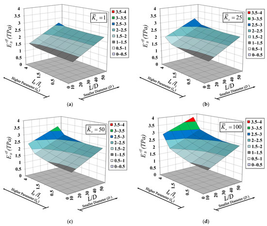
Figure 7.
Variation of effective Young’s modulus with SWCNT diameter and material length-scale parameter for various elastic substrate stiffness: (a) , (b) , (c) , and (d) .
6.2. Simulation II: Free Vibration Analysis
Simulation II focuses on free vibration responses of nanobar–substrate systems with two analysis cases. The first one examines the effects of material length-scale parameters and elastic substrate stiffness on the fundamental natural frequency, while the second one investigates the influences of the nanobar slenderness ratio (surface energy effect) and elastic substrate stiffness on natural frequencies for the first three vibration modes.
6.2.1. Effect of Material Length-Scale Parameters on the Fundamental Natural Frequency of SWCNT–Substrate Medium Systems
In this analysis case, a clamped–clamped SWCNT embedded in the substrate medium shown in Figure 8 is employed to investigate the influence of material length-scale parameters on the natural frequency. The material and geometric properties as well as the surface modulus of the SWCNT follow those employed in Simulation I. The mass density of the SWCNT is 1,370 kg/m3, as given by Jena et al. [63]. Two non-dimensional parameters, and , are employed to vary two material length-scale parameters associated with the dilation gradient, , and the deviatoric stretch gradient, , while the dimensionless substrate-stiffness parameter, , of Equation (48) is employed to vary the elastic substrate stiffness, . The ranges of these parameters are , , and . The classical and non-classical boundary conditions of the clamped–clamped SWCNT follow those suggested by Akgöz and Civalek [59]:

Figure 8.
Clamped–clamped SWCNT embedded in the substrate medium: free vibration analysis.
Based on the properties of the SWCNT and the substrate medium employed in this analysis case, only the solution case I () of Equation (40) is activated. Substituting the non-trivial solution, , of Equation (40) into Equation (39) and enforcing the boundary conditions of Equation (51) yields the following matrix relation:
The condition yields the following characteristic equation:
Therefore, the explicit form of the natural frequency for the clamped–clamped SWCNT–substrate medium system can be obtained from Equation (53) as:
with being the vibration mode ().
Figure 9 plots variations of the normalized natural frequency, , for the first vibration mode () with non-dimensional material length-scale parameters ( and ) for various values of the dimensionless substrate-stiffness parameter, . The “classical” natural frequency, , for the first vibration mode is obtained with the bar–substrate medium model, in which material small-scale and surface energy effects are both excluded. Point A shown in Figure 9 represents the normalized natural frequency, , when only the surface energy effect is considered (). It is observed that the surface energy effect consistently enhances the system stiffness, thus increasing the natural frequency (). However, this stiffening phenomenon is diminished by a stiffer substrate medium. The value of the normalized natural frequency, , deceases from 1.098 to 1.056 when the value of the dimensionless substrate-stiffness parameter, , increases from 1 to 10. An increase in the normalized natural frequency, , associated with the material small-scale effect is also noticed in Figure 9. Both non-dimensional material length-scale parameters ( and ) enhance the system stiffness, but at different degrees of enhancement. The system stiffness enhancement associated with the dilation gradient, , is more pronounced than that associated with the deviatoric stretch gradient, . This observation was noticed by Akgöz and Civalek [59] as well. However, this system stiffening enhancement becomes less pronounced when a substrate medium becomes stiffer.
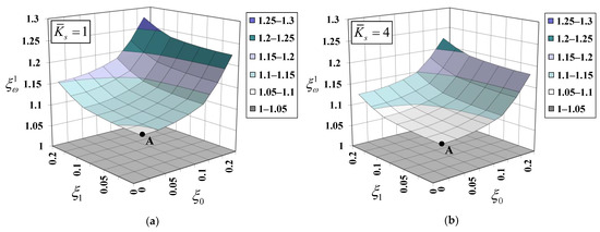
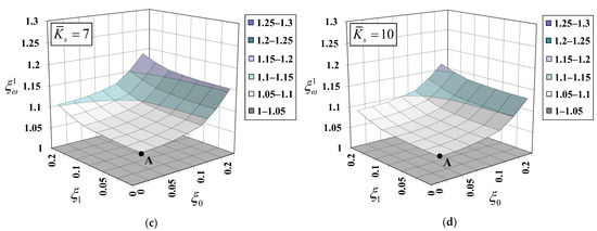
Figure 9.
Variation of normalized natural frequency for the first vibration mode with material length-scale parameters for various elastic substrate stiffnesses: (a) , (b) , (c) , and (d) .
.
6.2.2. Effect of Surface-Free Energy on Natural Frequencies of SWCNT–Substrate Medium Systems
To assess the surface energy effect on the system natural frequency, a clamped–free SWCNT embedded in the substrate medium shown in Figure 10 is employed in this analysis case. The material and geometric properties as well as the surface modulus of the SWCNT follow those employed in the previous analysis case. Two non-dimensional material length-scale parameters, and , are kept constant at 0.1. System parameters assessed herein are the SWCNT slenderness ratio, , and the elastic substrate stiffness, . The slenderness ratio, , is employed to specify the SWCNT diameter parameter and ranges from 5 to 50. A specified value of the slenderness ratio, , can be obtained by keeping = 10 nm and varying . The corresponding wall thickness, , of the SWCNT is equal to , thus keeping the ratio constant at 3.44. This specific value of is given by Anvari [66]. The dimensionless substrate-stiffness parameter, , of Equation (48) is employed to vary the elastic substrate stiffness, , and ranges from 1 to 10. The classical and non-classical boundary conditions follow those suggested by Akgöz and Civalek [59], as presented in Equations (46) and (47). Following the properties of the SWCNT and substrate medium employed in this analysis case, the solution case I () of Equation (40) is activated. Substituting the non-trivial solution, , of Equation (40) into Equation (39) and enforcing the boundary conditions of Equations (46) and (47) yields the following matrix relation:
where and .

Figure 10.
Cantilever SWCNT–substrate medium system: free vibration analysis.
The condition yields the following characteristic equation:
Therefore, the explicit form of the natural frequency for the clamped–free SWCNT–substrate medium system can be obtained from Equation (56) as:
with being the vibration mode ().
Figure 11 plots variations of the normalized natural frequency, , for the first three vibration modes () with the SWCNT slenderness ratio, , for various values of the dimensionless substrate-stiffness parameter, . The “classical” natural frequency, , is obtained with the bar–substrate medium model, in which material small-scale and surface energy effects are both excluded. As pointed out by Ponbunyanon et al. [69], the bar surface area/bulk volume ratio increases with the increasing bar slenderness ratio, thus rendering the surface energy effect more pronounced. Figure 11 shows that the normalized natural frequencies , , and increase with the increasing slenderness ratio, (decreasing diameter, ), especially for higher vibration modes. This observation implies that the stiffening phenomenon induced by the surface energy magnifies all system natural frequencies and is in good agreement with that of Ebrahimi et al. [70]. However, this system stiffening enhancement becomes less pronounced when a substrate medium becomes stiffer, especially for the first vibration mode. In other words, the size-dependency induced by the surface-free energy is stabilized by a stiff substrate medium.
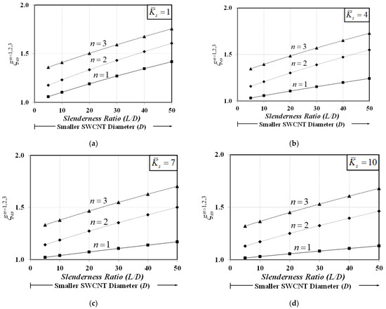
Figure 11.
Variation of normalized natural frequencies for the first three vibration modes with SWCNT diameter for various elastic substrate stiffnesses: (a) , (b) , (c) , and (d) .
7. Conclusions
The present work proposed a novel bar–substrate medium model with the inclusion of material small-scale and surface energy effects for both static and free vibration analyses of SWCNT–substrate medium systems. The material small-scale effect of the SWCNT was represented by the modified strain-gradient theory, while the surface energy effect was considered by the Gurtin–Murdoch surface model. The Winkler foundation model was employed to account for the interactive mechanism between the SWCNT and its surrounding substrate medium. Within the framework of Hamilton’s principle, the system equation of motion as well as associated initial and boundary conditions were derived in a consistent manner. To show the essence of the material small-scale effect, the surface energy effect, and the surrounding substrate medium on static and free vibration responses of SWCNT–substrate medium systems, two numerical simulations were employed.
The first numerical simulation collected two analysis cases and focused on static responses of SWCNT–substrate medium systems. The first analysis case showed that the modified strain-gradient bar model was able to represent the material small-scale effect under the constant axial-force state, thus eliminating the famous paradoxical characteristic of the Eringen nonlocal bar model. The material small-scale effect accounted for by the modified strain-gradient theory led to a system-stiffness enhancement. The second analysis case showed that the effective Young’s modulus, , of the SWCNT–substrate medium system was enlarged upon increasing the dilation-gradient small-scale parameter, , especially for large values of dimensionless substrate-stiffness parameters, (stiff substrate media), and lower values of the SWCNT slenderness ratio, (stubby SWCNT).
The second numerical simulation contained two analysis cases and emphasized on free vibration responses of SWCNT–substrate medium systems. The first analysis case demonstrated that the normalized fundamental frequency of the SWCNT–substrate medium system increased with the increasing non-dimensional material length-scale parameters, particularly for low values of dimensionless substrate-stiffness parameters, (soft substrate media). However, the frequency enhancement associated with the dilation gradient, , was more pronounced than that associated with the deviatoric stretch gradient, . The second analysis case showed that the normalized natural frequencies , , and increased with the increasing slenderness ratio, (more pronounced surface energy effect), especially for higher vibration modes. However, this system frequency enhancement became less noticeable when the substrate medium became stiffer, especially for the first vibration mode.
Author Contributions
Conceptualization, S.L. and W.S.-L.; methodology, S.L. and W.S.-L.; software, W.S.-L.; validation, S.L., W.S.-L., J.R. and P.S.; formal analysis, S.L. and W.S.-L.; investigation, S.L., H.M.-S., T.I. and H.Z.; data curation, S.L. and W.S.-L.; writing—original draft preparation, S.L. and W.S.-L.; writing—review and editing, S.L., W.S.-L. and H.M.-S.; visualization, S.L. and W.S.-L.; supervision, S.L., H.M.-S., J.R. and H.Z.; project administration, S.L. and W.S.-L.; funding acquisition, S.L. and W.S.-L. All authors have read and agreed to the published version of the manuscript.
Funding
This research was funded by TRF Senior Research Scholar, Grant RTA 6280012 (Thailand), and by the Office of the Permanent Secretary, Ministry of Higher Education, Science, Research and Innovation, Grant No. RGNS 64-134 (Thailand).
Institutional Review Board Statement
Not applicable.
Informed Consent Statement
Not applicable.
Data Availability Statement
Data are available upon reasonable request from the corresponding author.
Acknowledgments
This study was supported by TRF Senior Research Scholar under Grant RTA 6280012 (Thailand), and by the Office of the Permanent Secretary, Ministry of Higher Education, Science, Research and Innovation, under Grant No. RGNS 64-134 (Thailand). Any opinions expressed in this paper are those of the authors and do not reflect the views of the sponsoring agencies. Special thanks go to a senior lecturer Wiwat Sutiwipakorn for reviewing and correcting the English of this paper.
Conflicts of Interest
The authors declare no conflict of interest.
References
- Thostenson, E.T.; Ren, Z.; Chou, T.W. Advances in the science and technology of carbon nanotubes and their composites: A review. Compos. Sci. Technol. 2001, 61, 1899–1912. [Google Scholar] [CrossRef] [Green Version]
- Hornyak, G.L.; Moore, J.J.; Tibbals, H.F.; Dutta, J. Fundamentals of Nanotechnology; Taylor & Francis Inc.: Bosa Roca, FL, USA, 2008. [Google Scholar]
- Yurish, S.Y. Sensors and Biosensors, MEMS Technologies and Its Applications; International Frequency Sensor Association (Ifsa) Publishing: Barcelona, Spain, 2014. [Google Scholar]
- O’Donnell, J.; Kim, M.; Yoon, H.S. A review on electromechanical devices fabricated by additive manufacturing. J. Manuf. Sci. Eng. 2017, 139, 1080. [Google Scholar] [CrossRef]
- Zare, M.; Solaymani, S.; Shafiekhani, A.; Kulesza, S.; Ţălu, Ş.; Bramowicz, M. Evolution of rough-surface geometry and crystalline structures of aligned TiO2 nanotubes for photoelectrochemical water splitting. Sci. Rep. 2018, 8, 10870. [Google Scholar] [CrossRef] [PubMed] [Green Version]
- Ţălu, Ş.; Marković, Z.; Stach, S.; Marković, B.T.; Ţălu, M. Multifractal characterization of single wall carbon nanotube thin films surface upon exposure to optical parametric oscillator laser irradiation. Appl. Surf. Sci. 2014, 289, 97–106. [Google Scholar] [CrossRef]
- Kim, J.; Ahn, S.Y.; Um, S.H. Bead-immobilized multimodal molecular beacon-equipped DNA machinery for specific RNA target detection: A prototypical molecular nanobiosensor. Nanomaterials 2021, 11, 1617. [Google Scholar] [CrossRef]
- Liu, M.; Zhao, K. Engineering active micro and nanomotors. Micromachines 2021, 12, 687. [Google Scholar] [CrossRef]
- Chandrasekaran, A.R.; Trivedi, R.; Halvorsen, K. Ribonuclease-responsive DNA nanoswitches. Cell. Rep. Phys. Sci. 2020, 1, 100117. [Google Scholar] [CrossRef]
- Maity, R.; Maity, N.P.; Guha, K.; Baishya, S. Analysis of fringing capacitance effect on the performance of MEMS based micromachined ultrasonic air transducer. Micro Nano Lett. 2018, 13, 872–877. [Google Scholar] [CrossRef]
- Rackauskas, S.; Barbero, N.; Barolo, C.; Viscardi, G. ZnO nanowire application in chemoresistive sensing: A review. Nanomaterials 2017, 7, 381. [Google Scholar] [CrossRef] [Green Version]
- He, F.; Liu, J.; Zhu, K.D. Optomechanical atomic force microscope. Nanotechnology 2021, 32, 85505. [Google Scholar] [CrossRef]
- Lam, D.C.C.; Yang, F.; Chong, A.C.M.; Wang, J.; Tong, P. Experiments and theory in strain gradient elasticity. J. Mech. Phys. Solids 2003, 51, 1477–1508. [Google Scholar] [CrossRef]
- Li, X.F.; Wang, B.L.; Lee, K.Y. Size effects of the bending stiffness of nanowires. J. Appl. Phys. 2009, 105, 74306. [Google Scholar] [CrossRef]
- Abazari, A.M.; Fotouhi, M.; Tavakkoli, H.; Rezazadeh, G. An experimental study for characterization of size-dependence in microstructures via electrostatic pull-in instability technique. Appl. Phys. Lett. 2020, 116, 244102. [Google Scholar] [CrossRef]
- Diao, J.; Gall, K.; Dunn, M.L. Atomistic simulation of the structure and elastic properties of gold nanowires. J. Mech. Phys. Solids 2004, 52, 1935–1962. [Google Scholar] [CrossRef]
- Cleri, F.; Ishida, T.; Collard, D.; Fujita, H. Atomistic simulation of plasticity in silicon nanowires. Appl. Phys. Lett. 2010, 97, 153106. [Google Scholar] [CrossRef]
- Chang, K.H.; Wang, Y. Sensitivity analysis for coupled atomistic and continuum simulations using bridging scale decomposition. Mech. Based Des. Struct. Mach. 2012, 40, 292–333. [Google Scholar] [CrossRef]
- Madani, S.H.; Sabour, M.H.; Fadaee, M. Molecular dynamics simulation of vibrational behavior of annular graphene sheet: Identification of nonlocal parameter. J. Mol. Graphics Modell. 2018, 79, 264–272. [Google Scholar] [CrossRef]
- Bétermin, L.; Friedrich, M.; Stefanelli, U. Lattice ground states for embedded-atom models in 2D and 3D. Lett. Math. Phys. 2021, 111, 107. [Google Scholar] [CrossRef]
- Babaei, H.; Shahidi, A.R. Small-scale effects on the buckling of quadrilateral nanoplates based on nonlocal elasticity theory using the Galerkin method. Arch. Appl. Mech. 2011, 81, 1051–1062. [Google Scholar] [CrossRef]
- Akgöz, B.; Civale, Ö. Analysis of micro-sized beams for various boundary conditions based on the strain gradient elasticity theory. Arch. Appl. Mech. 2012, 82, 423–443. [Google Scholar] [CrossRef]
- Karami, B.; Janghorban, M. On the mechanics of functionally graded nanoshells. Int. J. Eng. Sci. 2020, 153, 103309. [Google Scholar] [CrossRef]
- Jazi, S.H. Nonlinear vibration of an elastically connected double Timoshenko nanobeam system carrying a moving particle based on modified couple stress theory. Arch. Appl. Mech. 2020, 90, 2739–2754. [Google Scholar]
- Juntarasaid, C.; Pulngern, T.; Chucheepsakul, S. A variational method for post-buckling analysis of end-supported nanorods under self-weight with surface stress effect. Arch. Appl. Mech. 2021, 91, 1021–1035. [Google Scholar] [CrossRef]
- Eringen, A.C. Nonlocal polar elastic continua. Int. J. Eng. Sci. 1972, 10, 1–16. [Google Scholar] [CrossRef]
- Eringen, A.C. On differential equations of nonlocal elasticity and solutions of screw dislocation and surface waves. J. Appl. Phys. 1983, 54, 4703–4710. [Google Scholar] [CrossRef]
- Mindlin, R.D. On the equations of elastic materials with micro-structure. Int. J. Solids Struct. 1965, 1, 73–78. [Google Scholar] [CrossRef]
- Mindlin, R.D. Influence of couple-stresses on stress concentrations. Exp. Mech. 1963, 3, 1–7. [Google Scholar] [CrossRef]
- Yang, F.; Chong, A.C.M.; Lam, D.C.C.; Tong, P. Couple stress based strain gradient theory for elasticity. Int. J. Solids Struct. 2002, 39, 2731–2743. [Google Scholar] [CrossRef]
- Reddy, J.N.; Pang, S.D. Nonlocal continuum theories of beams for the analysis of carbon nanotubes. J. Appl. Phys. 2008, 103, 23511. [Google Scholar] [CrossRef]
- Wang, C.M.; Kitipornchai, S.; Lim, C.W.; Eisenberger, M. Beam bending solutions based on nonlocal Timoshenko beam theory. J. Eng. Mech. 2008, 134, 475–481. [Google Scholar] [CrossRef]
- Juntarasaid, C.; Pulngern, T.; Chucheepsakul, S. Bending and buckling of nanowires including the effects of surface stress and nonlocal elasticity. Phys. E Low-Dimens. Syst. Nanostruc. 2012, 46, 68–76. [Google Scholar] [CrossRef]
- Barretta, R.; Feo, L.; Luciano, R.; Marotti de Sciarra, F. Application of an enhanced version of the Eringen differential model to nanotechnology. Composites Part B 2016, 96, 274–280. [Google Scholar] [CrossRef]
- Ebrahimi, F.; Shafiei, N. Application of Eringen’s nonlocal elasticity theory for vibration analysis of rotating functionally graded nanobeams. Smart Struct. Syst. 2016, 17, 837–857. [Google Scholar] [CrossRef]
- Limkatanyu, S.; Sae-Long, W.; Horpibulsuk, S.; Prachasaree, W.; Damrongwiriyanupap, N. Flexural responses of nanobeams with coupled effects of nonlocality and surface energy. ZAMM J. Appl. Math. Mech. 2018, 98, 1771–1793. [Google Scholar] [CrossRef]
- Nguyen, T.B.; Reddy, J.N.; Rungamornrat, J.; Lawongkerd, J.; Senjuntichai, T.; Luong, V.H. Nonlinear analysis for bending, buckling and post-buckling of nano-beams with nonlocal and surface energy effects. Int. J. Struct. Stab. Dyn. 2019, 19, 1950130. [Google Scholar] [CrossRef]
- Sayyad, A.S.; Ghugal, Y.M. Bending, buckling and free vibration analysis of size-dependent nanoscale FG beams using refined models and Eringen’s nonlocal theory. Int. J. Appl. Mech. 2020, 12, 2050007. [Google Scholar] [CrossRef]
- Lal, R.; Dangi, C. Dynamic analysis of bi-directional functionally graded Timoshenko nanobeam on the basis of Eringen’s nonlocal theory incorporating the surface effect. Appl. Math. Comput. 2021, 395, 125857. [Google Scholar] [CrossRef]
- Peddieson, J.; Buchanan, G.R.; McNitt, R.P. Application of nonlocal continuum models to nanotechnology. Int. J. Eng. Sci. 2003, 41, 305–312. [Google Scholar] [CrossRef]
- Romano, G.; Barretta, R.; Diaco, M.; De Sciarra, F.M. Constitutive boundary conditions and paradoxes in nonlocal elastic nanobeams. Int. J. Mech. Sci. 2017, 121, 151–156. [Google Scholar] [CrossRef]
- Koutsoumaris, C.C.; Eptaimeros, K.G.; Zisis, T.; Tsamasphyros, G.J. A straightforward approach to Eringen’s nonlocal elasticity stress model and applications for nanobeams. AIP Conf. Proc. 2016, 1790, 150018. [Google Scholar]
- Ma, H.M.; Gao, X.L.; Reddy, J.N. A microstructure-dependent Timoshenko beam model based on a modified couple stress theory. J. Mech. Phys. Solids 2008, 56, 3379–3391. [Google Scholar] [CrossRef]
- Cammarata, R.C. Surface and interface stress effects in thin films. Prog. Surf. Sci. 1994, 46, 1–38. [Google Scholar] [CrossRef] [Green Version]
- Miller, R.E.; Shenoy, V.B. Size-dependent elastic properties of nanosized structural elements. Nanotechnology 2000, 11, 139–147. [Google Scholar] [CrossRef]
- Tinte, S.; Stachiotti, M.G. Atomistic simulation of surface effects in BaTiO3. AIP Conf. Proc. 2000, 535, 273. [Google Scholar]
- Gurtin, M.E.; Murdoch, A.I. A continuum theory of elastic material surface. Arch. Ration. Mech. Anal. 1975, 57, 291–323. [Google Scholar] [CrossRef]
- Gurtin, M.E.; Murdoch, A.I. Surface stress in solids. Int. J. Solids Struct. 1978, 14, 431–440. [Google Scholar] [CrossRef]
- Bhushan, B. Springer Handbook of Nanotechnology; Springer: Berlin, Germany, 2010. [Google Scholar]
- Limkatanyu, S.; Damrongwiriyanupap, N.; Prachasaree, W.; Sae-Long, W. Modeling of axially loaded nanowires embedded in elastic substrate media with inclusion of nonlocal and surface effects. J. Nanomater. 2013, 2013, 635428. [Google Scholar] [CrossRef]
- Limkatanyu, S.; Prachasaree, W.; Damrongwiriyanupap, N.; Kwon, M. Exact stiffness matrix for nonlocal bars embedded in elastic foundation media: The virtual-force approach. J. Eng. Math. 2014, 89, 163–176. [Google Scholar] [CrossRef]
- Sae-Long, W.; Limkatanyu, S.; Prachasaree, W.; Rungamornrat, J.; Sukontasukkul, P. A thermodynamics-based nonlocal bar-elastic substrate model with inclusion of surface-energy effect. J. Nanomater. 2020, 2020, 8276745. [Google Scholar] [CrossRef]
- Limkatanyu, S.; Sae-Long, W.; Mohammad-Sedighi, H.; Rungamornrat, J.; Sukontasukkul, P.; Prachasaree, W.; Imjai, T. Strain-gradient bar-elastic substrate model with surface-energy effect: Virtual-force approach. Nanomaterials 2022, 12, 375. [Google Scholar] [CrossRef]
- Barretta, R.; De Sciarra, F.M. A nonlocal model for carbon nanotubes under axial loads. Adv. Mater. Sci. Eng. 2013, 2013, 360935. [Google Scholar] [CrossRef] [Green Version]
- Sae-Long, W.; Limkatanyu, S.; Sukontasukkul, P.; Damrongwiriyanupap, N.; Rungamornrat, J.; Prachasaree, W. A fourth-order strain gradient bar-substrate model with nonlocal and surface effects for the analysis of nanowires embedded in substrate media. Facta Univ. Ser. Mech. Eng. 2021, 19, 657–680. [Google Scholar] [CrossRef]
- Narendar, S.; Gopalakrishnan, S. Ultrasonic wave characteristics of nanorods via nonlocal strain gradient models. J. Appl. Phys. 2010, 107, 084312. [Google Scholar] [CrossRef]
- Winkler, E. Die Lehre von der und Festigkeit; Dominicus: Prague, Czech Republic, 1867. [Google Scholar]
- Altan, B.S.; Aifantis, E.C. On some aspects in the special theory of gradient elasticity. J. Mech. Behav. Mater. 1997, 8, 231–282. [Google Scholar] [CrossRef]
- Akgöz, B.; Civalek, Ö. Longitudinal vibration analysis for microbars based on strain gradient elasticity theory. J. Vib. Control 2014, 20, 606–616. [Google Scholar] [CrossRef]
- Limkatanyu, S.; Sae-Long, W.; Prachasaree, W.; Kwon, M. Improved nonlinear displacement-based beam element on a two-parameter foundation. Eur. J. Environ. Civ. Eng. 2015, 19, 649–671. [Google Scholar] [CrossRef]
- Dinçkal, C.; Alemder, B.N.; Gülkan, P.H. Dynamics of a beam-column element on an elastic foundation. Can. J. Civ. Eng. 2016, 43, 685–701. [Google Scholar] [CrossRef]
- Benvenuti, E.; Simone, A. One-dimensional nonlocal and gradient elasticity: Closed-form solution and size effect. Mech. Res. Commun. 2013, 48, 46–51. [Google Scholar] [CrossRef]
- Jena, S.K.; Chakraverty, S.; Malikan, M.; Tornabene, F. Stability analysis of single-walled carbon nanotubes embedded in winkler foundation placed in a thermal environment considering the surface effect using a new refined beam theory. Mech. Based Des. Struct. Mach. 2021, 49, 581–595. [Google Scholar] [CrossRef]
- Fleck, N.A.; Muller, G.M.; Ashby, M.F.; Hutchinson, J.W. Strain gradient plasticity: Theory and experiment. Acta. Metall. Mater. 1994, 42, 475–487. [Google Scholar] [CrossRef]
- Chong, A.C.M.; Lam, D.C.C. Strain gradient plasticity effect in indentation hardness of polymers. J. Mater. Res. 1999, 14, 4103–4110. [Google Scholar] [CrossRef]
- Anvari, A. The influence of CNT structural parameters on the properties of CNT and CNT-reinforced epoxy. Int. J. Aerosp. Eng. 2020, 2020, 4873426. [Google Scholar] [CrossRef]
- Demir, C.; Mercan, K.; Numanoglu, H.M.; Civalek, O. Bending response of nanobeams resting on elastic foundation. J. Appl. Comput. Mech. 2018, 4, 105–114. [Google Scholar]
- He, J.; Lilley, C.M. Surface effect on the elastic behavior of static bending nanowires. Nano. Lett. 2008, 8, 1798–1802. [Google Scholar] [CrossRef]
- Ponbunyanon, P.; Limkatanyu, S.; Kaewjuea, W.; Prachasaree, W.; Chub-Uppakarn, T. A novel beam-elastic substrate model with inclusion of nonlocal elasticity and surface energy effects. Arabian J. Sci. Eng. 2016, 41, 4099–4113. [Google Scholar] [CrossRef]
- Ebrahimi, F.; Shaghaghi, G.R.; Boreiry, M. A semi-analytical evaluation of surface and nonlocal effects on buckling and vibrational characteristics of nanotubes with various boundary conditions. Int. J. Struct. Stab. Dyn. 2016, 16, 1550023. [Google Scholar] [CrossRef]
Publisher’s Note: MDPI stays neutral with regard to jurisdictional claims in published maps and institutional affiliations. |
© 2022 by the authors. Licensee MDPI, Basel, Switzerland. This article is an open access article distributed under the terms and conditions of the Creative Commons Attribution (CC BY) license (https://creativecommons.org/licenses/by/4.0/).