Article

Zirconia-Doped Methylated Silica Membranes via Sol-Gel Process: Microstructure and Hydrogen Permselectivity

School of Urban Planning and Municipal Engineering, Xi’an Polytechnic University, Xi’an 710048, China
*
Author to whom correspondence should be addressed.
Nanomaterials 2022, 12(13), 2159; https://doi.org/10.3390/nano12132159
Submission received: 19 May 2022 / Revised: 6 June 2022 / Accepted: 20 June 2022 / Published: 23 June 2022
(This article belongs to the Special Issue Nanomaterials for Chemical Engineering)

Abstract

:
In order to obtain a steam-stable hydrogen permselectivity membrane, with tetraethylorthosilicate (TEOS) as the silicon source, zirconium nitrate pentahydrate (Zr(NO3)4·5H2O) as the zirconium source, and methyltriethoxysilane (MTES) as the hydrophobic modifier, the methyl-modified ZrO2-SiO2 (ZrO2-MSiO2) membranes were prepared via the sol-gel method. The microstructure and gas permeance of the ZrO2-MSiO2 membranes were studied. The physical-chemical properties of the membranes were characterized by Fourier transform infrared spectroscopy (FTIR), X-ray photoelectron spectroscopy (XPS), X-ray diffraction (XRD), transmission electron microscopy (TEM), scanning electron microscope (SEM), and N2 adsorption–desorption analysis. The hydrogen permselectivity of ZrO2-MSiO2 membranes was evaluated with Zr content, temperature, pressure difference, drying control chemical additive (glycerol) content, and hydrothermal stability as the inferred factors. XRD and pore structure analysis revealed that, as nZr increased, the MSiO2 peak gradually shifted to a higher 2θ value, and the intensity gradually decreased. The study found that the permeation mechanism of H2 and other gases is mainly based on the activation–diffusion mechanism. The separation of H2 is facilitated by an increase in temperature. The ZrO2-MSiO2 membrane with nZr = 0.15 has a better pore structure and a suitable ratio of micropores to mesopores, which improved the gas permselectivities. At 200 °C, the H2 permeance of MSiO2 and ZrO2-MSiO2 membranes was 3.66 × 10⁻⁶ and 6.46 × 10⁻⁶ mol·m−2·s−1·Pa−1, respectively. Compared with the MSiO2 membrane, the H2/CO2 and H2/N2 permselectivities of the ZrO2-MSiO2 membrane were improved by 79.18% and 26.75%, respectively. The added amount of glycerol as the drying control chemical additive increased from 20% to 30%, the permeance of H2 decreased by 11.55%, and the permselectivities of H2/CO2 and H2/N2 rose by 2.14% and 0.28%, respectively. The final results demonstrate that the ZrO2-MSiO2 membrane possesses excellent hydrothermal stability and regeneration capability.

Graphical Abstract

1. Introduction

It is well-known that hydrogen is a clean energy source [1]. At present, there are many ways to obtain H2, but the biggest problem preventing its commercialization is the purification and separation of H2. The purification of H2 can be achieved in three main ways: pressure swing adsorption, cryogenic distillation, and membrane separation [2,3]. Although pressure swing adsorption and cryogenic distillation can be operated commercially, the economic benefits are low. The main commercial application of membranes in gas separation is the separation of hydrogen from nitrogen, methane, and argon in an ammonia sweep gas stream. In the past few years, hundreds of new polymer materials have been reported, and only eight or nine polymer materials have been used to make gas separation membrane bases. Surprisingly few of them were used to make industrial membranes [4]. Membrane separation technology is also one of the most promising hydrogen purification methods. At high temperatures, the H2 separation membrane has attracted much attention in the application of membrane reactors, for example, in the steam reforming of natural gas. The characteristics of lower energy consumption and investment cost, as well as simple operation, have made the membrane separation method widely concerned. Compared to other techniques of hydrogen purification, the membrane separation method offers more energy efficiency and environmental friendliness. The quality of the separation membrane directly affects the separation performance. Therefore, it is very necessary to choose suitable materials to prepare efficient and stable membrane materials [5].
In recent years, research on hydrogen separation membranes has mainly focused on molecular sieves, alloys, and microporous silica [6,7,8,9]. Prominently, silica membranes have received extensive attention for H2 separation due to their advantages such as high permselectivity and considerable thermal stability [10]. Amorphous silica membranes derived from sol-gel and chemical vapor deposition (CVD) methods received an enormous amount of attention [11,12]. They have a stable chemical structure and molecular sieve mechanism, which can separate hydrogen across a broad temperature range [13]. However, silica membranes have demonstrated poor steam and thermal stability. Due to the hydrophilic nature of silica membranes, if they are frequently exposed to humid, low-temperature atmospheres, the flux and permselectivity of H2 will largely be reduced [14,15]. The study found that the addition of hydrophobic groups can reduce the affinity of silica for water and improve gas permselectivity [15]. At this stage, methyl, vinyl, perfluorodecalin, etc., are often used in the hydrophobic modification of gas permeation separation in silica membrane, and the effect of increasing the hydrothermal stability is obvious [16]. Wei et al. [17] prepared perfluorodecyl hydrophobically modified silica membranes. The results demonstrated that the addition of perfluorodecyl made the modified silica membrane change from hydrophilic to hydrophobic. The membrane exhibited excellent hydrothermal stability at 250 °C and a water vapor molar ratio of 5%. Debarati et al. [18] hydrophobically modified the surface of ceramic membranes with polydimethylsiloxane to achieve a contact angle of 141°. It shows that the surface of the ceramic membrane with the methyl group is highly hydrophobic. Somayeh et al. [19] also demonstrated that vinyl-modified silica particles can improve the hydrophobic properties of the membrane.
It is well-known that the addition of metal oxides (such as TiO2 [20,21], Al2O3 [22,23], Fe2O3 [24], CoO [25], and ZrO2 [26,27]) can not only enhance the hydrothermal stability of the membrane, but also further improve the antifouling ability and performance of the membrane. This indicates that the incorporation of metal oxides can form mixed oxide network structures that are more stable than amorphous silica materials [28,29]. In particular, ZrO2 is an excellent transition metal oxide, which is often utilized in studies of gas membrane separation. Li et al. [30] prepared a zirconia membrane via the polymeric sol-gel method, which possessed H2 permeance of about 5 × 10⁻⁸ mol·m−2·s−1·Pa−1, H2/CO2 permselectivity of 14, and outstanding hydrothermal stability under a steam pressure of 100 KPa. Gu et al. [31] used the sol-gel method to prepared the microporous zirconia membrane. After being treated with 0.50 mol·L−1 of H2SO4, the hydrogen permeance was (2.8 to 3.0) × 10−6 mol·Pa−1·m−2·s−1. The H2 permselectivities of the equimolar binary system were 6 and 9, respectively. Doping ZrO2 in the SiO2 matrix can improved the hydrophobicity and hydrothermal stability of the membrane matrix, and further enhance the gas permeability. Numerous studies have been carried out on ZrO2-doped silica materials/membranes. According to mesoporous stabilized zirconia intermediate layers, Gestel et al. [32] revealed a much better membrane setup. For various CO2/N2 combinations, the as-prepared membrane demonstrated permselectivities of 20–30 and CO2 permeances of 1.5 to 4 m3/(m2∙h∙bar). Ahn et al. [33] prepared a silica-zirconia membrane with hydrogen permselectivity on a porous alumina support using tetraethyl orthosilicate (TEOS) and tert-butanol zirconium (IV) under 923 K conditions by chemical vapor deposition. The H2 permeance of the obtained membrane was 3.8 × 10⁻⁷ mol·m−2·s−1·Pa−1, and the permselectivities for CO2 and N2 were 1100 and 1400, respectively. Hove et al. [34] compared the gas permeation properties of a hybrid silica (BTESE) membrane, Zr-doped BTESE membrane, and silica membrane before and after hydrothermal treatment under the same circumstances. At 100 °C, the hybrid silica membrane and Zr-doped BTESE membrane maintained good hydrothermal stability, while the silica membrane lost selectivity for all the studied gases. After hydrothermal treatment at 200 or 300 °C, the CO2 permeance of the Zr-doped BTESE membrane decreased significantly, and the H2/CO2 permselectivity increased significantly, by 65.71%. So far, many scholars have demonstrated the effect of different conditions during preparation on the properties of zirconia-doped silica materials/membranes. The influence of the Zr/Si molar ratio on the microstructure of the membrane and the permeability of the gas is crucial. Unfortunately, there are few reports in this regard. Furthermore, the effects of methyl modification on the microstructure and steam stability of ZrO2-SiO2 membranes were rarely described in papers. Some scholars have found that adding a drying control chemical additive (DCCA) in the process of preparing the membrane via the sol-gel method can effectively reduce the uneven shrinkage of the membrane during the heating process and during the calcining process [35], and improve the gas permselectivity of the membrane.
In this paper, methyl-modified ZrO2-SiO2 (ZrO2-MSiO2) materials/membranes with various Zr/Si molar ratios (nZr) were fabricated. Glycerol was chosen to be the DCCA. The impact of nZr on the microstructures and H2 permselectivities of ZrO2-MSiO2 membranes was thoroughly addressed. The water vapor stability of ZrO2-MSiO2 membranes was investigated further by comparing the gas permeability characteristics of the ZrO2-MSiO2 membranes before and after steam treatment. The heat regeneration performance of ZrO2-MSiO2 membranes was also investigated.

2. Materials and Methods

2.1. Preparation of MSiO2 Sols

The MSiO2 sols were prepared by tetraethylorthosilicate (TEOS, purchased from Xi’an chemical reagent Co., Ltd., Xi’an, China) as a silica source, methyltriethoxysilane (MTES, purchased from Hangzhou Guibao Chemical Co., Ltd., Hangzhou, China) as a hydrophobic modified agent, anhydrous ethanol (EtOH, purchased from Tianjin Branch Micro-Europe Chemical Reagent Co., Ltd., Tianjin, China) as a solvent, and nitric acid (HNO3, purchased from Sichuan Xilong Reagent Co., Ltd., Chengdu, China) as a catalyst. To begin, TEOS, MTES, and EtOH were completely combined in a three-necked flask using a magnetic stirrer. The flask was correctly immersed in an ice-water combination. The solution was then agitated for 50 min using a magnetic stirrer to ensure thorough mixing. The H2O and HNO3 combination was then dropped into the mixture while it was still being stirred. The reaction mixture was then agitated in a three-necked flask at a constant temperature of 60 °C for 3 h to yield the MSiO2 sol.

2.2. Preparation of ZrO2 Sols

In a three-necked flask, 0.6 M zirconium nitrate pentahydrate (Zr(NO3)4·5H2O, purchased from Tianjin Fuchen Chemical Reagent Co., Ltd., Tianjin, China) and 0.2 M oxalic acid (C2H2O4·2H2O, purchased from Tianjin HedongHongyan Chemical Reagent Co., Ltd., Tianjin, China) solutions were combined at a molar ratio of 4.5:1.0 and agitated. The aforementioned mixture was then treated with 35% (v/v) glycerol (GL, purchased from Tianjin Kemiou Chemical Reagent Co., Ltd., Tianjin, China), and stirring was maintained in a water bath at 50 °C for 3 h to yield the ZrO2 sols.

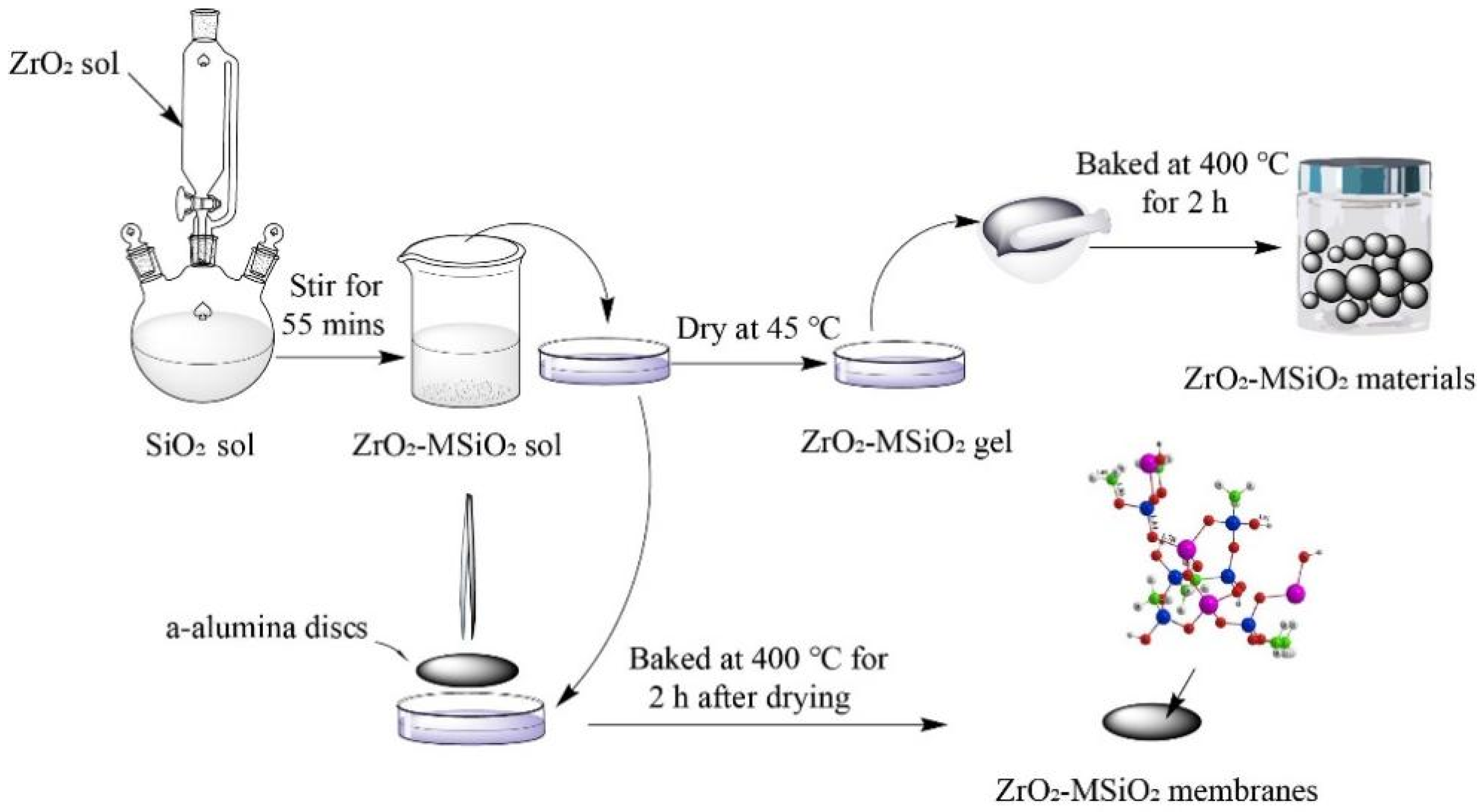
2.3. Preparation of ZrO2-MSiO2 Sols

The ZrO2 sols were aged for 12 h at 25 °C. The ZrO2 sols and EtOH were then added to the MSiO2 sols and stirred for 60 min to create the required ZrO2-MSiO2 sols. The nZr ratio was 0, 0.08, 0.15, 0.3, and 0.05. The ZrO2-MSiO2 sols were diluted three times with ethanol after 12 h. GL was used as a drying control agent at 0%, 10%, 20%, and 30% (DCCA). After 60 min of stirring, ZrO2-MSiO2 sols with varied GL contents were obtained.

2.4. Preparation of ZrO2-MSiO2 Materials

The ZrO2-MSiO2 sols were then placed individually in petri plates for gelation at 30 °C. The gel materials were ground and pulverized with a mortar, and then calcined at a heating rate of 0.5 °C·min−1 at 400 °C for 2 h under nitrogen atmosphere protection, and then cooled down naturally. The ZrO2-MSiO2 materials with different nZr were prepared. The ZrO2-MSiO2 materials with nZr = 0 are also referred to as “MSiO2” materials.

2.5. Preparation of ZrO2-MSiO2 Membranes

The ZrO2-MSiO2 membranes were coated on top of composite interlayers supported by porous α-alumina discs. The discs are 5 mm-thick and 30 mm in diameter, with a porosity of 40% and an average pore size of 100 nm. ZrO2-MSiO2 membranes were effectively prepared by dip-coating the substrates in three-fold ethanol-diluted silica sol for 7 s, then drying and calcining them. Each sample was dried at 30 °C for 3 h before being calcined at 400 °C in a temperature-controlled furnace in a N2 environment with a ramping rate of 0.5 °C·min−1 and a dwell period of 2 h. The dip-coating-drying-calcining process was repeated three times. Figure 1 demonstrates the preparation process of the ZrO2-MSiO2 materials/membranes. The ZrO2-MSiO2 membranes with nZr = 0 are also referred to as “MSiO2” membranes.

2.6. Steam Treatment and Regeneration of ZrO2-MSiO2 Membranes

The ZrO2-MSiO2 membranes were subjected to a 7-day steam stability test in which they were placed into saturated steam at 25 °C. After steam treatment, for thermal regeneration of ZrO2-MSiO2 membranes, they were processed at a calcination temperature of 350 °C, with the same calcination technique as before. The gas permeances of ZrO2-MSiO2 membranes were investigated after steam treatment and regeneration, respectively.

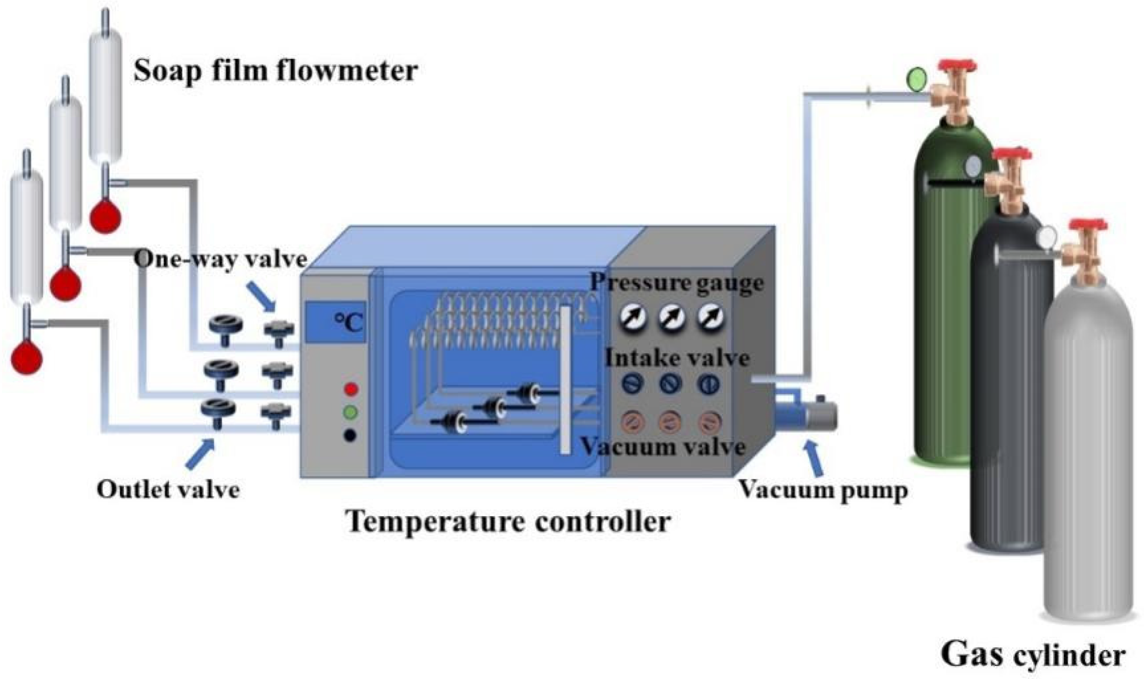
2.7. Characterizations

Using Fourier transform infrared spectroscopy, the functional groups of ZrO2-MSiO2 materials were characterized (FTIR, Spotlight 400 and Frontier, PerkinElmer Corporation, Waltham, MA, USA), and the wavelength measuring range was 400 to 4000 cm−1 using the KBr compression technique. Using a Rigaku D/max-2550pc X-ray diffractometer (XRD, Rigaku D/max-2550pc, Hitachi, Tokyo, Japan) with CuKα radiation at 40 kV and 40 mA, the ZrO2-MSiO2 materials’ phase structure was found. The X-ray photoelectron spectra (XPS) were acquired on a K-Alpha X-ray photoelectron spectroscope from Thermo Fisher Scientific with AlKα excitation and were calibrated regarding the signal of adventitious carbon (XPS, ESCALAB250xi, Thermo Scientific, Waltham, MA, USA). The binding energy estimates were derived using the C (1s) line at 284.6 eV as the reference point. Transmission electron microscopy (TEM, JEM 2100F, JEOL, Tokyo, Japan) was utilized to investigate the ZrO2-MSiO2 powders’ crystallization. Operating at 5 kV, scanning electron microscopy (SEM, JEOL JSM-6300, Hitachi, Tokyo, Japan) was utilized to study the surface morphologies of the ZrO2-MSiO2 membranes. N2 adsorption–desorption measurements were conducted using an automated Micromeritics, ASAP2020 analyzer (ASAP 2020, Micromeritics, Norcross, GA, USA). The ZrO2-MSiO2 materials’ BET surface area, pore volume, and pore size distribution were determined.
Figure 2 is a schematic of the experimental setup used to evaluate the performance of single gas permeation. Prior to the experiment, the pressure and temperature were set to the desired values for thirty minutes to allow the gas permeation to stabilize. The permeation properties of MSiO2 and ZrO2-MSiO2 membranes were evaluated using H2, CO2, and N2. The gas permeability was determined based on the outlet gas flow. The gas permselectivity values (ideal permselectivities) were calculated by the permeance ratio between two gases.

3. Results

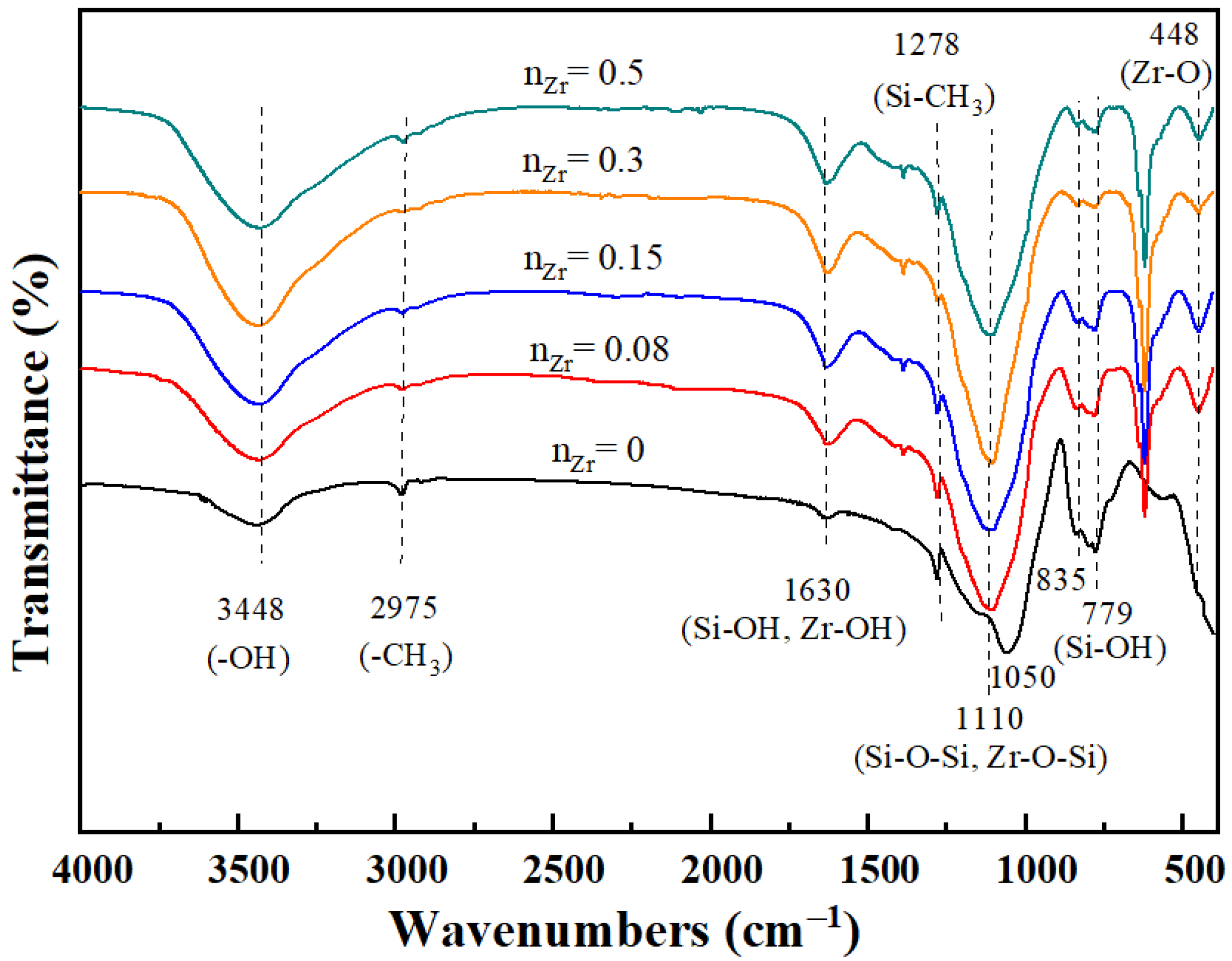
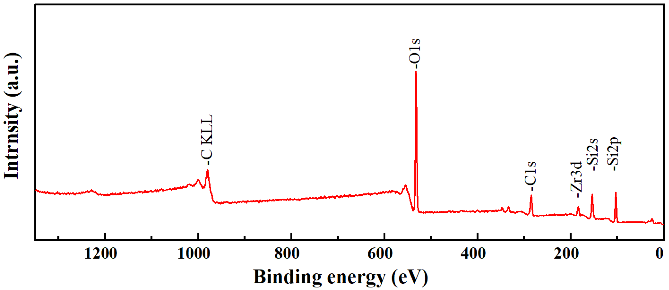
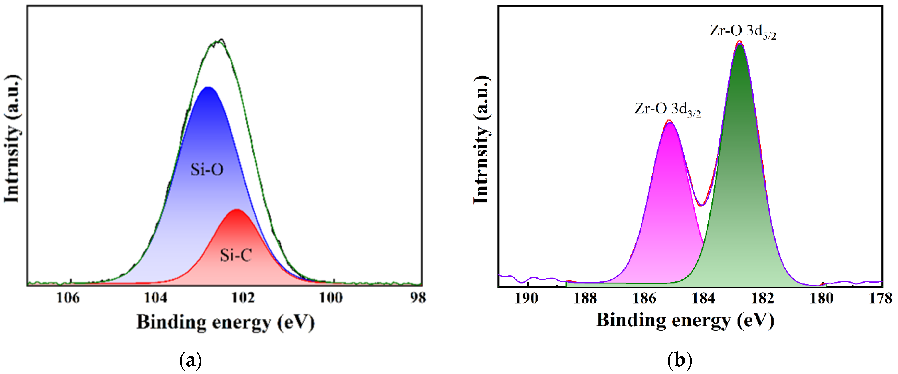
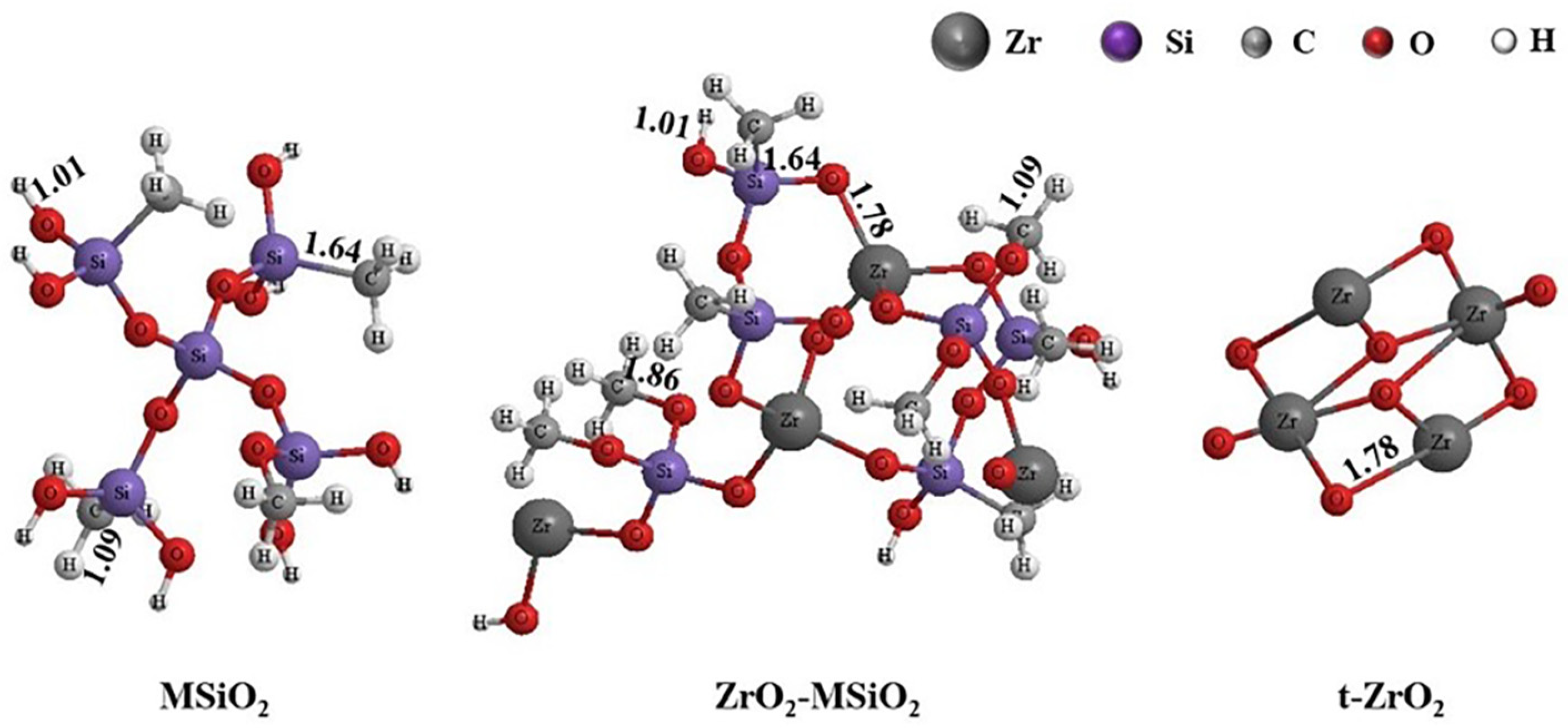
3.1. Chemical Structure Analysis

FTIR spectra were used to investigate the functional groups of ZrO2-MSiO2 materials. The FTIR spectra of ZrO2-MSiO2 materials containing various nZr contents are displayed in Figure 3. The absorption peak at around 3448 cm−1 was assigned to the stretching and bending vibration of the -OH group from the absorbed water. The absorption peak at 1630 cm−1 corresponds to Si-OH and Zr-OH on the surface of ZrO2-MSiO2 materials [36]. The antisymmetric stretching vibration absorption peak -CH3 at 2985 cm−1 was mainly from unhydrolyzed TEOS and MTES. The absorption peak at 1278 cm−1 was attributed to the Si-CH3 group. It is also the main hydrophobic functional group of the membrane. The absorption peak observed at 1050 cm−1 was attributed to the Si-O-Si bond [37]. Compared with the materials with nZr = 0, the materials with nZr = 0.08–0.5 all showed a new absorption peak at the wavenumber of 448 cm−1. This was related to the formation of Zr-O bonds [38]. Meanwhile, with the increase of nZr, the peak at 1050 cm−1 shifted to around 1100 cm−1. This may be ascribed to the fact that partial substitution of Zr atoms for Si atoms in the Si-O-Si network to form Zr-O-Si bonds occurred [39], breaking the symmetry of SiO2 and leading to the shift of peak positions. However, there was no obvious Zr-O-Si bond in the FTIR spectrum of ZrO2-MSiO2 materials due to the overlap of the Zr-O-Si bond with Si-O-Si [40]. Furthermore, the decrease in the intensity of the silanol band at 779 and 835 cm−1 with increasing nZr could be attributed to the substitution of Si-OH bonds by Zr-O-Si bonds [41]. It demonstrates the formation of Zr-O-Si bonds in the produced materials.

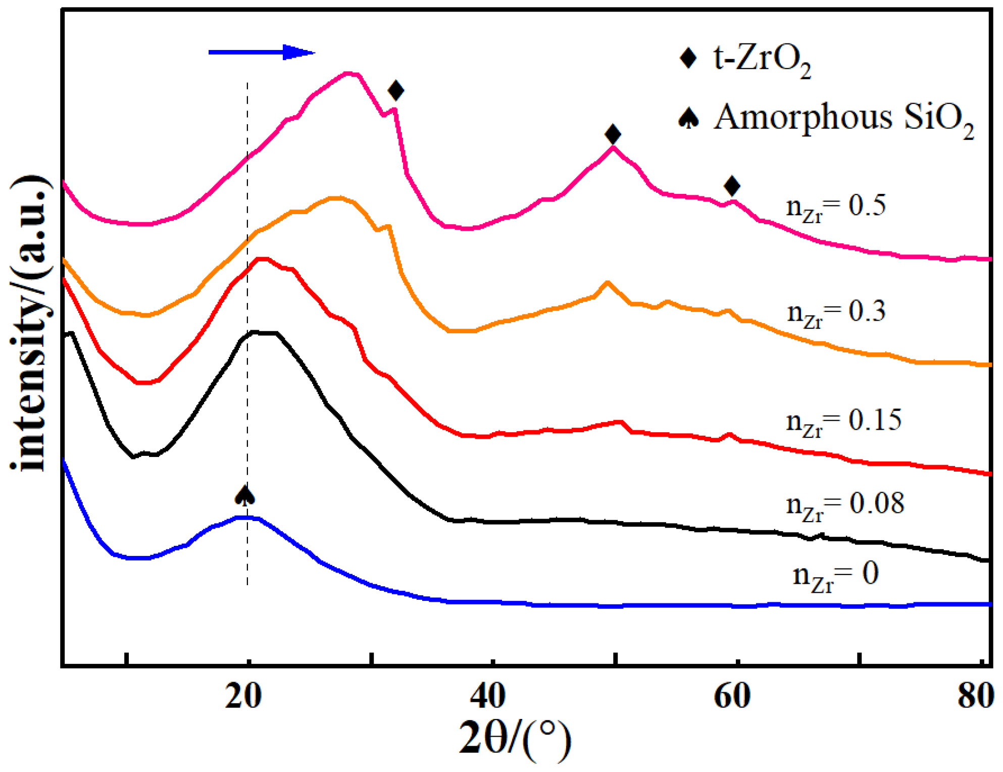
3.2. Phase Structure Analysis
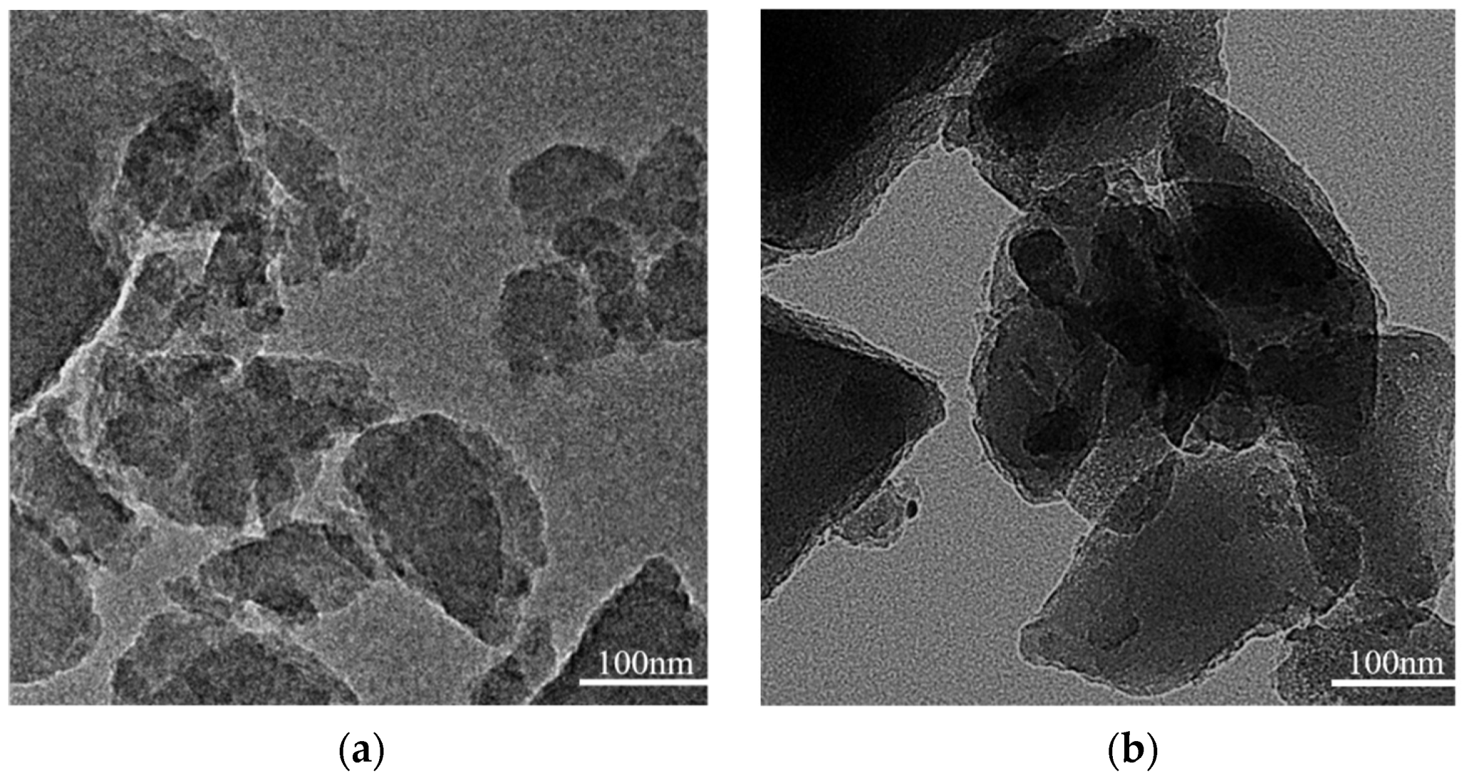
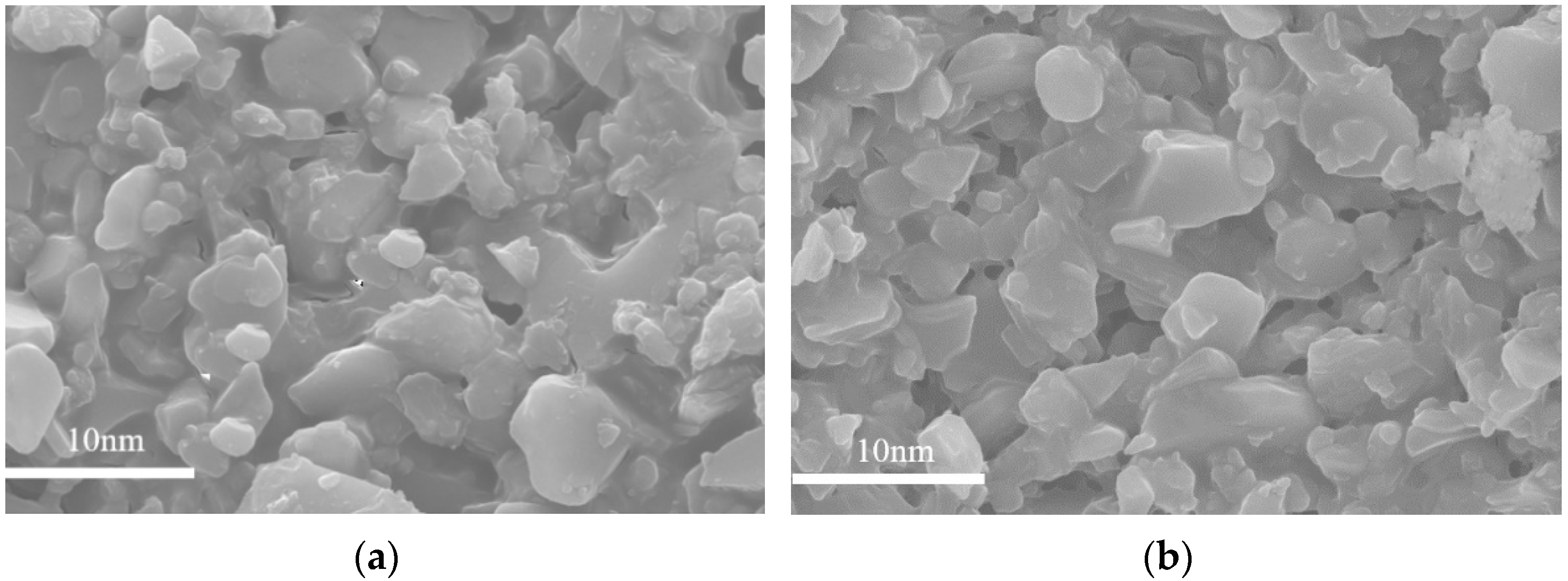
The XRD patterns of the ZrO2-MSiO2 materials with varied nZr are presented in Figure 4. The peaks of amorphous SiO2 were concentrated at 2θ = 23.1° [42]. The SiO2 peak moved progressively towards higher 2θ values as nZr rose, and it slowly dropped in intensity. This is attributable to the replacement of the portion of silicon atoms by the inserted Zr atoms, producing Zr-O-Si bonds, resulting in a drop in the SiO2 concentration. The peaks corresponding to a crystalline tetragonal structure of zirconia are clearly apparent in the ZrO2-MSiO2 materials with nZr = 0.15–0.5. The (101), (112), and (202) reflection planes of the body-centered ZrO2 (t-ZrO2) tetragonal phase were ascribed to the large diffraction peaks occurring at 60.2°, 50.7°, and 30.2°, respectively (JCPDS No. 79-1771). XRD analysis demonstrated that with the growth of the Zr concentration, the peak intensity corresponding to t-ZrO2 progressively increased. In other words, the content of t-ZrO2 increased with the growth in Zr content. Combined with the FTIR analysis, the Zr element in ZrO2-MSiO2 materials may exist in the form of Zr-O-Si bonds and t-ZrO2.
To further investigate the presence of Zr and Si species in the ZrO2-MSiO2 materials, the XPS measurement was conducted. The survey XPS spectrum of ZrO2-MSiO2 material with nZr = 0.15 is shown in Figure 5. Figure 5 demonstrates that C, O, Si, and Zr elements are present in the ZrO2-MSiO2 material, which indicates the successful incorporation of Zr into the silica frameworks. Figure 6 presents the Si 2p and Zr 3d XPS spectra of the ZrO2-MSiO2 sample with nZr = 0.15. In Figure 6a, the peaks at the binding energies of 102.8 and 104.7 eV correspond to Si-C and Si-O bonds, respectively. In Figure 6b, the peaks at 186.6 and 183.3 eV correspond to the Zr-O 3d3/2 and Zr-O 3d5/2 peaks, respectively.

3.3. TEM Analysis

The TEM micrographs of the ZrO2-MSiO2 material with nZr = 0 and 0.15 at 400 °C under nitrogen atmosphere are illustrated in Figure 7. Figure 7a depicts that the silica particles in MSiO2 materials are amorphous, while in Figure 7b, a small amount of particles with darker color appear and are mixed in the silica skeleton, which may be due to the presence of t-ZrO2. Overall, the ZrO2-MSiO2 materials with nZr = 0.15 still maintained the amorphous state.

3.4. Pore Structure Analysis

The N2 adsorption-desorption isotherm of the ZrO2-MSiO2 materials with various nZr are shown in Figure 8a. According to the Brunauer-Deming-Deming-Teller (BDDT) classification, the ZrO2-MSiO2 materials showed a type I adsorption isotherm, while nZr = 0 indicated the formation of microporous structures. The isotherms for the four samples (nZr = 0.08–0.5) all showed a similar trend, which could be categorized as type IV isotherms. However, the shapes of the hysteresis loops for the four samples were different, implying the variation of pore structures. A significant proportion of adsorption occurred in the range of low relative pressure, P/P0 < 0.1, indicating that the materials contain a large quantity of micropores. The shape of the hysteresis loop of the ZrO2-MSiO2 materials with nZr = 0.5 was altered, indicating the presence of larger mesopores or macropores. In addition, the distributions of pore size for all samples are depicted in Figure 8b. It is found that the samples with nZr = 0.08–0.5 showed a broader pore size distribution and a larger mean pore size than the samples with nZr = 0. The conclusion was also confirmed by the pore structure parameters of ZrO2-MSiO2 materials with various nZr in Table 1. The average pore size, BET specific surface area, and total pore volume of the ZrO2-MSiO2 materials gradually increased with nZr = 0.08 and 0.15, and the pore size distribution became wider. However, the total pore volume of the ZrO2-MSiO2 materials with nZr = 0.3 and 0.5 decreased instead. The fact is that the bond length of Zr-O (1.78 Å) was slightly longer than that of Si-O (1.64 Å) [43]. Figure 9 shows the molecular structure models of MSiO2, ZrO2-MSiO2, and t-ZrO2 crystallites, respectively. Hence, the formation of Zr-O-Si bonds contributes to the formation of pores. With the increase of Zr content, more and more t-ZrO2 crystallites were formed and distributed in the framework of MSiO2 materials, and the internal pore structure of the ZrO2-MSiO2 materials was hindered from shrinking and pore collapse, resulting in the decrease of the BET surface area and pore volume. From Table 1, it can be seen that the ZrO2-MSiO2 materials with nZr = 0.15 had the maximal total pore volume (0.43 cm3·g−1), BET surface area (616.77 m2·g−1), and the minimum mean pore size (2.19 nm).

3.5. Gas Permselectivity Analysis

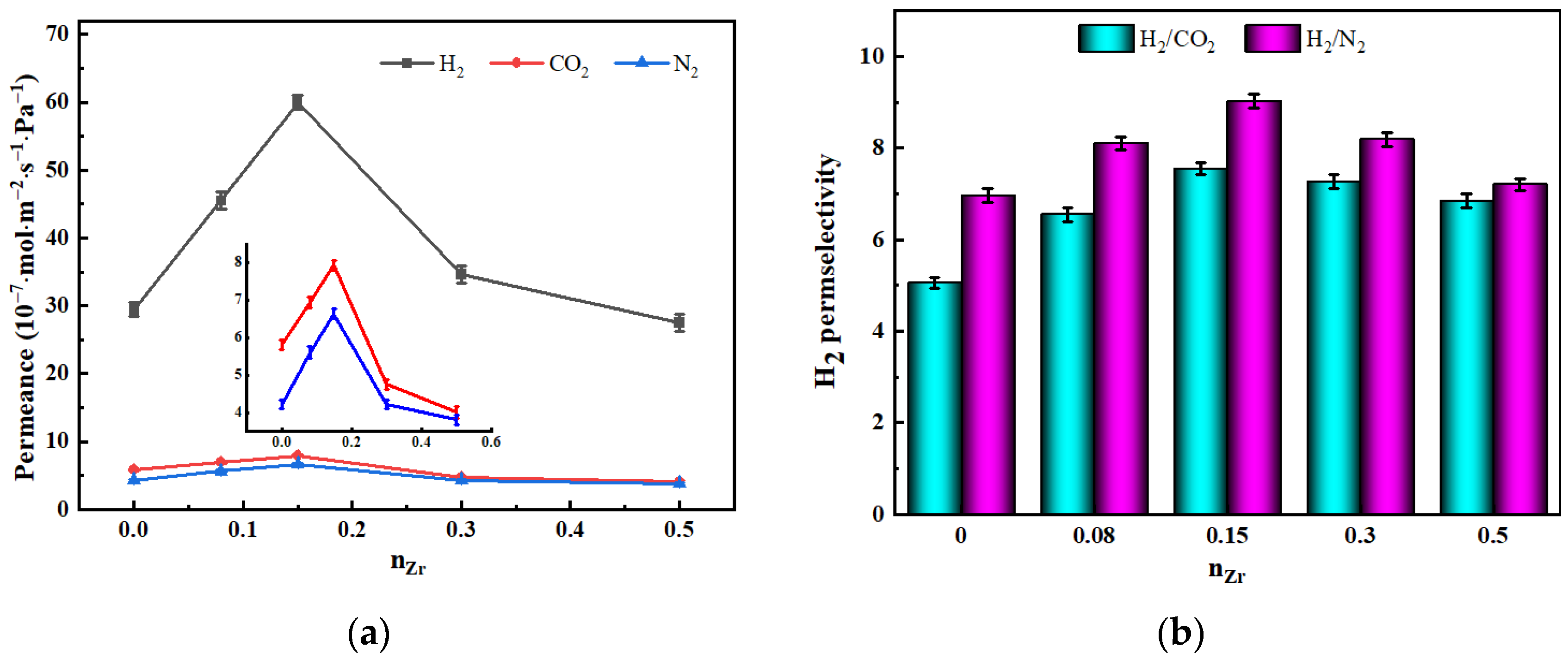
3.5.1. The Influence of nZr

Figure 10 depicts the influence of nZr on the gas permeabilities and H2 permselectivities of ZrO2-MSiO2 membranes with varying nZr and 0% DCCA addition at 25 °C and 0.1 MPa. In Figure 10a, with the increase of nZr, the H2, CO2, and N2 permeances of the samples increased until nZr = 0.15, and then decreased. Compared with the MSiO2 membranes (nZr = 0), the H2, CO2, and N2 permeance of the ZrO2-MSiO2 membranes with nZr = 0.15 increased by 50.95%, 26.74%, and 36.36%, respectively. From the pore structure analysis (Table 1), the overall pore volumes of the ZrO2-MSiO2 membranes grew somewhat with increasing nZr until nZr = 0.15, and then decreased, which can explain why the ZrO2-MSiO2 membranes with nZr = 0.15 had the highest permeance to each gas. For the same membrane, the order of gas molecular permeance is H2 > CO2 > N2. Gas permeance decreased with increasing dk (0.289, 0.33, and 0.364 nm, respectively), indicating that all membranes exhibited molecular sieve properties. However, when nZr ≥ 0.15, the permeance of CO2 decreased more closely to that of N2. This behavior was related to the fact that following heat treatment at 400 °C, the Zr-O-Si bonds and t-ZrO2 crystallites generated in the ZrO2-SiO2 membranes will generate a significant number of Brønsted acid sites. High acidity leads to a reduction in the affinity of the membranes for CO2, hence lowering the CO2 permeance [44].
It can be observed from Figure 10b that compared with MSiO2 membranes, the H2/CO2 and H2/N2 permselectivities of ZrO2-MSiO2 membranes with nZr = 0.15 increased by 22.93% and 33.04%, respectively. Combined with the previous characterization test, it was found that the ZrO2-MSiO2 membranes with nZr = 0.15 had a good pore structure, which is beneficial to improve the permselectivity of gas. In addition, the acidic sites formed by the ZrO2-MSiO2 membranes reduced the affinity of the membranes for CO2 and helped to separate it from H2. However, the permselectivities of ZrO2-MSiO2 membranes after nZr = 0.15 showed a decreasing trend. Compared with the ZrO2-MSiO2 membranes with nZr = 0.15, the H2/CO2 and H2/N2 permselectivities of the membranes with nZr = 0.5 decreased by 9.35% and 20.15%, respectively. As a result, just because the nZr concentration is larger, it does not indicate that the separation effect is better. Since the Zr-O and Si-O bonds in zirconium-substituted siloxane rings are longer than in pure siloxane rings, for the ZrO2-MSiO2 membranes with nZr = 0.5, the number of siloxane rings containing Zr increased, and the pore size of the membranes became larger. Meanwhile, a large number of t-ZrO2 crystals were produced, which led to the shrinkage of the pore structure inside the membranes and the collapse of the pores, resulting in the decrease of the permselectivities of the membranes.
SEM images of surface topography for MSiO2 and ZrO2-MSiO2 (nZr = 0.15) membranes calcined at 400 °C are shown in Figure 11. Compared to the MSiO2 membranes, the particle size and distribution of the ZrO2-MSiO2 membranes were more uniform, the membranes’ surfaces had no obvious defects, and the surface was uniform and smooth. The particle size of MSiO2 membranes was between 1.1 and 5.8 nm, while the particle size of ZrO2-MSiO2 membranes was between 1.3 and 8.9 nm. The formed ZrO2-MSiO2 membranes with a smooth surface and uniform membrane pores were more conducive to the gas permselectivitiy.

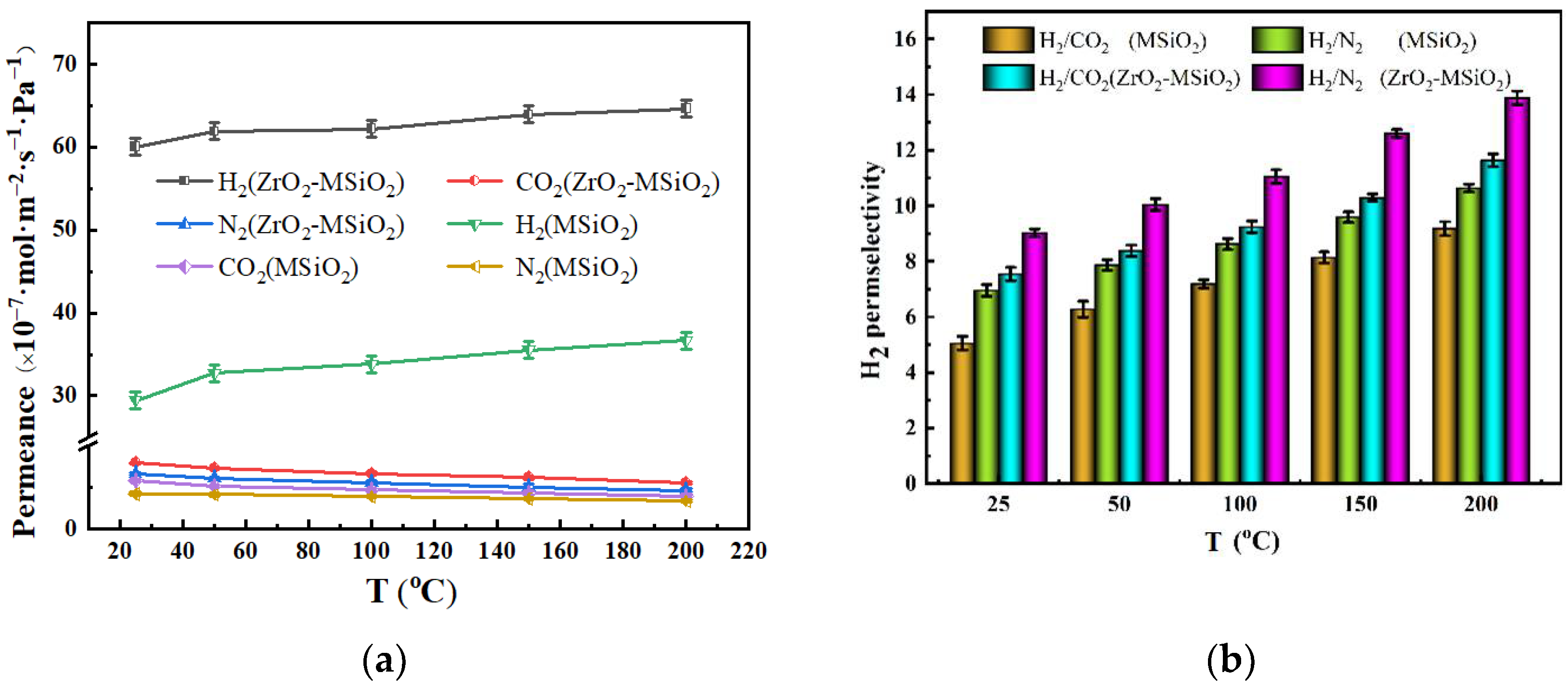
3.5.2. The Influence of Temperature

The permeances and permselectivities of the MSiO2 and ZrO2-MSiO2 (nZr = 0.15) membranes with 0% DCCA addition at a pressure difference of 0.1 MPa and temperature changing from 25 to 200 °C are shown in Figure 12. Obviously, with the increasing temperature, the permeance of H2 of MSiO2 and ZrO2-MSiO2 membranes increased gradually, as seen in Figure 12a. From 25 to 200 °C, the H2 permeance of MSiO2 and ZrO2-MSiO2 membranes rose by 19.66% and 7.12%, respectively, demonstrating that the H2 permeation behavior in the two membranes followed the activated diffusion transport mechanism. In contrast, the permeabilities of CO2 and N2 were similar to the Knudsen diffusion trend, whereby both slightly decreased. The CO2 permeance of MSiO2 and ZrO2-MSiO2 membranes decreased by 31.46% and 30.20% from 25 to 200 °C, respectively, and the N2 permeance decreased by 18.60% and 29.98%, respectively. The major explanations for the decrease in CO2 and N2 permeance were the violent movement of molecules and the rise in the mean free path as temperature increased.
In Figure 12b, it can be seen that the permselectivities in the membranes gradually increased with the increase of temperature. At 200 °C, compared with the MSiO2 membranes, the H2/CO2 and H2/N2 permselectivities of the ZrO2-MSiO2 membranes increased by 21.11% and 23.34%, respectively. The above results show that the ZrO2-MSiO2 membranes had better permselectivity and permeance of H2 than the MSiO2 membranes under the same conditions.
Combined with the preceding studies, it was determined that a rise in temperature facilitated the separation of H2 and that the separation process of H2 from CO2 and N2 is dominated by activation diffusion, which is described by the Arrhenius equation [45]:
P = P 0 exp ( E a R T )
In Formula (1), P is the permeation rate, Ea is the apparent activation energy, and P0 is a constant, which depends on the pore wall–gas molecule interaction, gas selective layer thickness, and pore shape and tortuosity [46]. For linear fitting, 1000/RT was used as the abscissa and lnP as the ordinate, and the slope of the fitting equation might be used to obtain the apparent activation energy. Figure 13 depicts the Arrhenius fitting diagrams for the three gases.
Figure 13 demonstrates that the apparent activation energy of H2 is positive, while that of various other gases is negative. This is related to the gas-activated transport behavior, whereby there are two parallel transmission channels for gas through the membrane: one is through selective micropores, with gas transport processed by a thermally activated surface diffusion mechanism in the micropore state [47], and the other is through larger pores [48]. The activation energies for CO2 and N2 are negative, indicating that there are permeation pathways large enough in these types of membranes to allow the diffusion of these larger gas. It is generally believed that Ea is composed of two parts [46], the adsorption heat, Qst, of gas on the surface of the membrane and the activation energy, Em, of gas flowing through the solid surface. The larger the Em is, the harder it is for the gas to diffuse, Ea = EmQst. Arrhenius equation parameter values are shown in Table 2. Table 2 shows that the Em values of the gases in the ZrO2-MSiO2 membrane are all less than those in the MSiO2 membrane. It shows that the structure of ZrO2-MSiO2 membranes is not as dense as that of MSiO2 membranes. This is in good accordance with the N2 adsorption–desorption results. This finding also shows that ZrO2 doping successfully diminishes the densification of the SiO2 network. The higher porosity of the ZrO2-MSiO2 membranes allows the gas to cross the membrane pore barrier using their kinetic energy. Therefore, the gas (H2, CO2, and N2) permeance of ZrO2-MSiO2 membranes is higher than that of MSiO2 membranes.
Table 3 displays the Ea of H2, pore diameter, H2 permeance, and H2 permselectivities for several membranes/films prepared by other researchers. It is challenging to concurrently enhance the membranes’ permselectivity and gas permeability, as seen in Table 3. Generally, the larger the average pore size of the membrane, the higher the permeance to H2, which is accompanied by a smaller Ea. Meanwhile, the Ea of H2 is related to the interaction of H2 with the membrane pore wall. It can be seen from Table 3 that the as-prepared ZrO2-MSiO2 membrane has a large H2 permselectivity compared to other membranes.

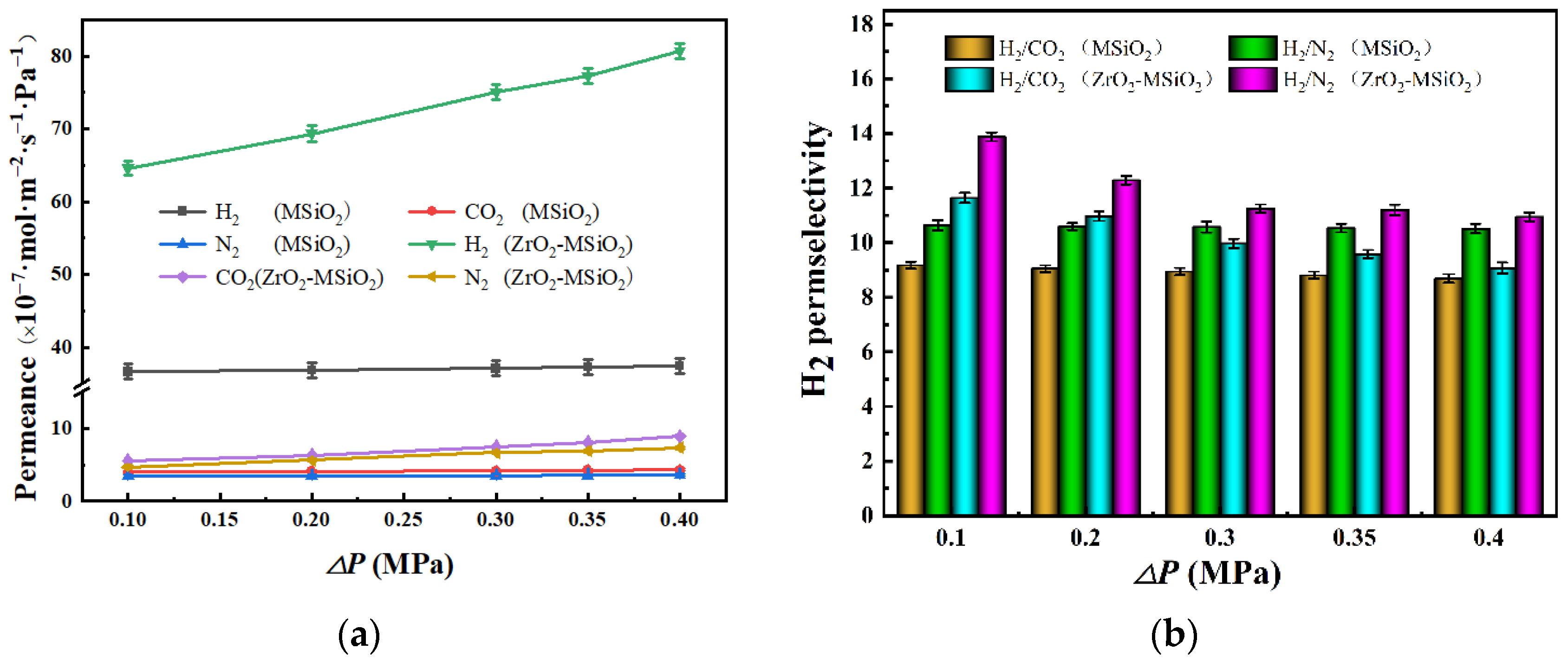
3.5.3. The Influence of Pressure Difference

Figure 14 illustrates the effect of pressure difference on the gas permeances and H2 permselectivities of MSiO2 and ZrO2-MSiO2 (nZr = 0.15) membranes at 200 °C with 0% DCCA addition. In Figure 14a, it can be observed that the H2 permeance of the ZrO2-MSiO2 membranes with nZr = 0.15 improved with the increase of the pressure difference, and the pressure dependence increased. However, the H2 permeance of MSiO2 membranes remained basically unchanged. The MSiO2 and ZrO2-MSiO2 membranes increased their H2 permeance by 2.16% and 19.96%, respectively, when the pressure was increased from 0.10 to 0.40 MPa. In Figure 14b, the H2 permselectivities of MSiO2 membranes did not change significantly, and the H2/CO2 and H2/N2 permselectivities decreased by 5.27% and 1.12%, respectively. However, the H2 permselectivities of the ZrO2-MSiO2 membranes with nZr = 0.15 changed greatly, where the H2/CO2 and H2/N2 permselectivities decreased by 22.04% and 21.12%, respectively. Clearly, it can be seen that the permselectivity of the ZrO2-MSiO2 membranes was reduced more than that of the MSiO2 membranes, that is, the pressure had a relatively small effect on the gas permeation of the MSiO2 membranes. This phenomenon is attributed to the relatively dense MSiO2 membranes with micropores as the main component. With the increase of the pressure difference between the two sides of the membranes, the power of the gas passing through the ZrO2-MSiO2 membranes increased, making it easier for the gas to pass through the mesopores or even the macropores, which has a greater impact on the permselectivity of the membranes. At the same time, it is shown that the H2 diffusion mechanism of ZrO2-MSiO2 membranes was different from that of MSiO2 membranes due to the influence of doping ZrO2. The gas transport in the ZrO2-MSiO2 membranes follows the surface diffusion mechanism. In addition, when the pressure difference increased to 0.4 MPa, the permselectivities of H2/CO2 and H2/N2 were still higher than their respective Knudsen diffusion (4.69 and 3.74, respectively), indicating that they still have good gas permeation performance under high pressure.

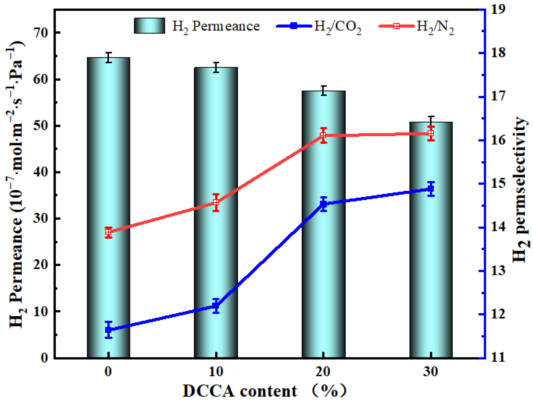
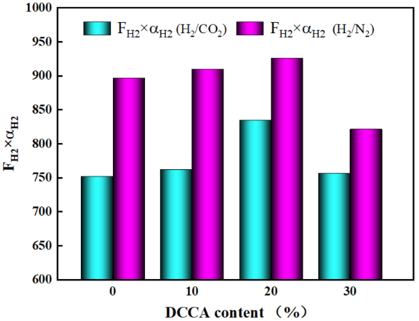
3.5.4. The Influence of the DCCA

Comparing and analyzing the previous results, it was found that the addition of DCCA (glycerol) by the sol-gel method can effectively reduce the uneven shrinkage of the membrane when it is heated during firing. The gas permeances and H2 permselectivities of ZrO2-MSiO2 membranes (nZr = 0.15) with various DCCA additions at 200 °C and 0.1 MPa are shown in Figure 15.
Figure 15 demonstrates that the H2 permeance of the ZrO2-MSiO2 membranes reduced by 21.30% as the DCCA addition increased from 0 to 30%. The permselectivities of H2/CO2 and H2/N2 increased by 21.77% and 14.07%, respectively. However, compared with the 20% membranes, the H2/CO2 and H2/N2 permselectivities of the membranes with the addition of 30% only increased by 2.14% and 0.28%, respectively. Figure 16 shows the relationship between DCCA (GL) contents and FH2 × αH2 (FH2 is the H2 permeance, αH2 is the permselective of H2). It was clearly observed that the addition of DCCA from 0 to 20% enhanced the FH2 × αH2 value, and after more than 20%, the FH2 × αH2 value showed a lower level. This is attributed to the fact that the addition of glycerol will gradually surround the sol particles, reduce the agglomeration caused by the collision of the colloid particles, accelerate the creation of the sol-gel network, and improve the stability of the sol structure [52]. In addition, the membrane layer collapsed and cracked easily during the drying and calcination processes, and the addition of glycerol can effectively reduce the liquid–gas surface tension to a certain extent, thereby protecting the gel skeleton from deformation [55]. However, the particles of the sol were surrounded by steric effects when too much GL was added, making the sol sticky and difficult to dry to form a membrane. The extension of the drying time makes the cross-linking of the sol more thorough and eventually leads to the densification of the membrane, which is not conducive to gas separation. From the above point of view, the membranes with 20% DCCA addition were the more worthy choice.

3.5.5. Steam Treatment and Regeneration Analysis

Figure 17 shows the effects of steam treatment and thermal regeneration on the gas permeances (H2, CO2, and N2) and H2 permselectivities of MSiO2 and ZrO2-MSiO2 (nZr = 0.15) membranes with 0% DCCA addition at a pressure difference of 0.1 MPa and 25 °C. The permeances of H2, CO2, and N2 for MSiO2 and ZrO2-MSiO2 membranes appear to have reduced after steam treatment. After steam aging for 7 days, the permeance of H2 for MSiO2 and ZrO2-MSiO2 membranes dropped by 20.63% and 3.70%, respectively, as compared to untreated fresh samples, and the permselectivities of H2/CO2 and H2/N2 for MSiO2 membranes decreased by 1.59% and 1.04%, respectively, whereas those of ZrO2-MSiO2 membranes increased by 0.09% and 0.43%, respectively.
The gas permeances (H2, CO2, and N2), as well as the permselectivities of H2/CO2 and H2/N2 for two membranes, all exhibit an increased trend after regeneration by calcination at 350 °C. However, as compared to untreated fresh samples, the H2 permeances of MSiO2 and ZrO2-MSiO2 membranes after regeneration dropped by 9.96% and 1.65%, respectively, whereas the permselectivities of H2/CO2 and H2/N2 for MSiO2 membranes improved by 1.12% and 4.71%, respectively, and those for ZrO2-MSiO2 membranes increased by 0.08% and 1.21%, respectively. The decrease in gas permeances in both membranes suggests that membrane pore shrinking occurs after calcination at 350 °C. Lower permeance and greater permselectivities are produced as a result of the smaller pores. This is attributed to the partial Zr atoms replacing the Si atoms in Si-O-Si to form more stable Zr-O-Si bonds, which further improves the hydrothermal stability of the membrane material. Therefore, the above results indicated that the ZrO2-MSiO2 membranes had a better hydrothermal stability and reproducibility than MSiO2 membranes.

4. Conclusions

The ZrO2-MSiO2 membranes were manufactured to enhance the steam stability and H2 permselectivity of SiO2 membranes. It was found that with the increase of ZrO2 content, the pore size distribution of the materials became wider and the average pore size increased, indicating that the doping of ZrO2 had the effect of expanding the pores. The ZrO2-MSiO2 membranes with nZr = 0.15 had a good pore structure and suitable micropore/mesoporous ratio, which is beneficial to improve the permeance of natural gas. At 200 °C, the H2/CO2 and H2/N2 permselectivities of ZrO2-MSiO2 membranes were 79.18% and 26.75% greater than those of MSiO2 membranes, respectively. Furthermore, when the pressure was increased to 0.4 MPa, the permselectivities were still higher than their respective Knudsen diffusion, indicating that they still had good gas permeance at high pressure. With the addition of DCCA from 20% to 30%, the H2/CO2 and H2/N2 permselectivities of ZrO2-MSiO2 membranes only increased by 2.14% and 0.28%, respectively, and the FH2 × αH2 value with 20% addition was the highest. In conclusion, it is worthwhile to choose 20% GL as the DCCA addition for ZrO2-MSiO2 membranes. Compared with the untreated fresh sample, after 7 days of water vapor aging, the permeance of ZrO2-MSiO2 membranes to H2 decreased by only 3.70%, and the permselectivities of H2/CO2 and H2/N2 increased by only 0.09% and 0.43%, respectively. After regeneration at 350 °C, the H2 permeance of the ZrO2-MSiO2 membranes decreased by 1.65%, and the permselectivities of H2/CO2 and H2/N2 increased by 0.08% and 1.21%. It is enough to show that the prepared ZrO2-MSiO2 membranes had a good hydrothermal stability and certain regeneration performance. In the future, the influence of high temperature (for example, ≥300 °C) and mixed gases on the gas permeances and permselectivies of ZrO2-MSiO2 membranes should be explored, which is important to the practical engineering applications.

Author Contributions

Conceptualization, L.W. and J.Y.; writing—original draft preparation, L.W. and J.Y.; funding acquisition, J.Y. All authors have read and agreed to the published version of the manuscript.

Funding

This work was supported by the Scientific Research Project of Shaanxi province of China (2022SF-287) and the Scientific Research Project of Shaanxi Education Department, China (19JC017).

Institutional Review Board Statement

Not applicable.

Informed Consent Statement

Not applicable.

Data Availability Statement

Not applicable.

Conflicts of Interest

The authors declare no conflict of interest.

References

  1. Nazir, H.; Louis, C.; Jose, S.; Prakash, J.; Muthuswamy, N.; Buan, M.E.; Flox, C.; Chavan, S.; Shi, X.; Kauranen, P.; et al. Is the H2 economy realizable in the foreseeable future? Part I: H2 production methods. Int. J. Hydrogen Energy 2020, 45, 13777–13788. [Google Scholar] [CrossRef]
  2. Nordio, M.; Wassie, S.A.; Van Sint Annaland, M.; Tanaka, D.A.P.; Sole, J.L.V.; Gallucci, F. Techno-economic evaluation on a hybrid technology for low hydrogen concentration separation and purification from natural gas grid. Int. J. Hydrogen Energy 2020, 46, 23417–23435. [Google Scholar] [CrossRef]
  3. Cai, L.; Cao, Z.; Zhu, X.; Yang, W. Improved hydrogen separation performance of asymmetric oxygen transport membranes by grooving in the porous support layer. Green Chem. Eng. 2020, 2, 96–103. [Google Scholar] [CrossRef]
  4. Lv, B.; Luo, Z.; Deng, X.; Chen, J.; Fang, C.; Zhu, X. Study on dry separation technology of a continuous gas-solid separation fluidized bed with a moving scraper (И)–Separation performance. Powder Technol. 2021, 377, 565–574. [Google Scholar] [CrossRef]
  5. Koutsonikolas, D.E.; Pantoleontos, G.; Karagiannakis, G.; Konstandopoulos, A.G. Development of H2 selective silica membranes: Performance evaluation through single gas permeation and gas separation tests. Sep. Purif. Technol. 2021, 264, 118432. [Google Scholar] [CrossRef]
  6. Wu, R.; Yue, W.; Li, Y.; Huang, A. Ultra-thin and high hydrogen permeable carbon molecular sieve membrane prepared by using polydopamine as carbon precursor. Mater. Lett. 2021, 295, 129863. [Google Scholar] [CrossRef]
  7. Singla, S.; Shetti, N.P.; Basu, S.; Mondal, K.; Aminabhavi, T.M. Hydrogen production technologies—Membrane based separation, storage and challenges. J. Environ. Manag. 2022, 302, 113963. [Google Scholar] [CrossRef]
  8. Yan, E.; Huang, H.; Sun, S.; Zou, Y.; Chu, H.; Sun, L. Development of Nb-Ti-Co alloy for high-performance hydrogen separating membrane. J. Membr. Sci. 2018, 565, 411–424. [Google Scholar] [CrossRef]
  9. Farina, L.; Santucci, A.; Tosti, S. Plasma Enhancement Gases separation via ceramic porous membranes for plasma exhaust processing system of DEMO. Fusion Eng. Des. 2021, 169, 112484. [Google Scholar] [CrossRef]
  10. Zhang, D.; Zhang, X.; Zhou, X.; Song, Y.; Jiang, Y.; Lin, B. Phase stability and hydrogen permeation performance of BaCo0·4Fe0·4Zr0·1Y0·1O3-δ ceramic membranes. Ceram. Int. 2021, 48, 9946–9954. [Google Scholar] [CrossRef]
  11. Bakoglidis, K.D.; Palisaitis, J.; Dos Santos, R.B.; Rivelino, R.; Persson, P.O.; Gueorguiev, G.K.; Hultman, L. Self-Healing in Carbon Nitride Evidenced As Material Inflation and Superlubric Behavior. ACS Appl. Mater. Interfaces 2018, 10, 16238–16243. [Google Scholar] [CrossRef] [Green Version]
  12. Kakanakova-Georgieva, A.; Gueorguiev, G.; Sangiovanni, D.G.; Suwannaharn, N.; Ivanov, I.G.; Cora, I.; Pécz, B.; Nicotra, G.; Giannazzo, F. Nanoscale phenomena ruling deposition and intercalation of AlN at the graphene/SiC interface. Nanoscale 2020, 12, 19470–19476. [Google Scholar] [CrossRef] [PubMed]
  13. Thirumal, V.; Yuvakkumar, R.; Kumar, P.S.; Ravi, G.; Keerthana, S.P.; Velauthapillai, D. Facile single-step synthesis of [emailprotected] hybrid nanocomposite by CVD method to remove hazardous pollutants. Chemosphere 2021, 286, 131733. [Google Scholar] [CrossRef] [PubMed]
  14. Kanezashi, M.; Asaeda, M. Hydrogen permeation characteristics and stability of Ni-doped silica membranes in steam at high temperature. J. Membr. Sci. 2006, 271, 86–93. [Google Scholar] [CrossRef]
  15. Rosli, A.; Ahmad, A.L.; Low, S.C. Anti-wetting polyvinylidene fluoride membrane incorporated with hydrophobic polyethylene-functionalized-silica to improve CO2 removal in membrane gas absorption. Sep. Purif. Technol. 2019, 221, 275–285. [Google Scholar] [CrossRef]
  16. Yang, J.; Chen, J. Hydrophobic modification and silver doping of silica membranes for H2/CO2 separation. J. CO2 Util. 2013, 3–4, 21–29. [Google Scholar] [CrossRef]
  17. Wei, Q.; Ding, Y.L.; Nie, Z.R.; Liu, X.G.; Li, Q.Y. Wettability, pore structure and performance of perfluorodecyl-modified silica membranes. J. Membr. Sci. 2014, 466, 114–122. [Google Scholar] [CrossRef]
  18. Mukherjee, D.; Kar, S.; Mandal, A.; Ghosh, S.; Majumdar, S. Immobilization of tannery industrial sludge in ceramic membrane preparation and hydrophobic surface modification for application in atrazine remediation from water. J. Eur. Ceram. Soc. 2019, 39, 3235–3246. [Google Scholar] [CrossRef]
  19. Karimiab, S.; Mortazavia, Y.; Khodadadia, A.A.; Holmgrenb, A.; Korelskiyc, D.; Hedlund, J. Functionalization of silica membranes for CO2 separation. Sep. Purif. Technol. 2020, 235, 116207. [Google Scholar] [CrossRef]
  20. Khan, A.A.; Maitlo, H.A.; Khan, I.A.; Lim, D.; Zhang, M.; Kim, K.-H.; Lee, J.; Kim, J.-O. Metal oxide and carbon nanomaterial based membranes for reverse osmosis and membrane distillation: A comparative review. Environ. Res. 2021, 202, 111716. [Google Scholar] [CrossRef]
  21. Kurt, T.; Topuz, B. Sol-gel Control on Mixed Network Silica Membranes for Gas Separation. Sep. Purif. Technol. 2020, 255, 117654. [Google Scholar] [CrossRef]
  22. Zhang, Y.; Huang, B.; Mardkhe, M.K.; Woodfield, B.F. Thermal and hydrothermal stability of pure and silica-doped mesoporous aluminas. Microporous Mesoporous Mater. 2019, 284, 60–68. [Google Scholar] [CrossRef] [Green Version]
  23. Gu, Y.; Hacarlioglu, P.; Oyama, S.T. Hydrothermally stable silica–alumina composite membranes for hydrogen separation. J. Membr. Sci. 2008, 310, 28–37. [Google Scholar] [CrossRef]
  24. Teo, H.T.; Siah, W.R.; Yuliati, L. Enhanced adsorption of acetylsalicylic acid over hydrothermally synthesized iron oxide-mesoporous silica MCM-41 composites. J. Taiwan Inst. Chem. Eng. 2016, 65, 591–598. [Google Scholar] [CrossRef]
  25. Uhlmann, D.; Smart, S.; da Costa, J.C.D. H2S stability and separation performance of cobalt oxide silica membranes. J. Membr. Sci. 2011, 380, 48–54. [Google Scholar] [CrossRef]
  26. Chang, C.H.; Gopalan, R.; Lin, Y.S. A comparative study on thermal and hydrothermal stability of alumina, titania and zirconia membranes. J. Membr. Sci. 1994, 91, 27–45. [Google Scholar] [CrossRef]
  27. Yoshida, K.; Hirano, Y.; Fujii, H.; Tsuru, T.; Asaeda, M. Hydrothermal stability and performance of silica-zirconia membranes for hydrogen separation in hydrothermal conditions. J. Chem. Eng. Jpn. 2001, 34, 523–530. [Google Scholar] [CrossRef] [Green Version]
  28. Díez, B.; Roldán, N.; Martín, A.; Sotto, A.; Perdigón-Melón, J.; Arsuaga, J.; Rosal, R. Fouling and biofouling resistance of metal-doped mesostructured silica/polyethersulfone ultrafiltration membranes. J. Membr. Sci. 2017, 526, 252–263. [Google Scholar] [CrossRef]
  29. Wang, L.; Yang, J.; Mu, R.; Guo, Y.; Hou, H. Sol-Gel Processed Cobalt-Doped Methylated Silica Membranes Calcined under N2 Atmosphere: Microstructure and Hydrogen Perm-Selectivity. Materials 2021, 14, 4188. [Google Scholar] [CrossRef]
  30. Li, L.; Hong, Q. Gas separation using sol–gel derived microporous zirconia membranes with high hydrothermal stability. Chin. J. Chem. Eng. 2015, 23, 1300–1306. [Google Scholar] [CrossRef]
  31. Gu, Y.; Kusakabe, K.; Morooka, S. Sulfuric acid-modified zirconia membrane for use in hydrogen separation. Sep. Purif. Technol. 2001, 24, 489–495. [Google Scholar] [CrossRef]
  32. Van Gestel, T.; Velterop, F.; Meulenberg, W.A. Zirconia-supported hybrid organosilica microporous membranes for CO2 separation and pervaporation. Sep. Purif. Technol. 2020, 259, 118114. [Google Scholar] [CrossRef]
  33. Ahn, S.J.; Takagaki, A.; Sugawara, T.; Kikuchi, R.; Oyama, S.T. Permeation properties of silica-zirconia composite membranes supported on porous alumina substrates. J. Membr. Sci. 2017, 526, 409–416. [Google Scholar] [CrossRef]
  34. Hove, M.T.; Luiten-Olieman, M.; Huiskes, C.; Nijmeijer, A.; Winnubst, L. Hydrothermal stability of silica, hybrid silica and Zr-doped hybrid silica membranes. Purif. Technol. 2017, 189, 48–53. [Google Scholar] [CrossRef]
  35. Goswami, K.P.; Pugazhenthi, G. Effect of binder concentration on properties of low-cost fly ash-based tubular ceramic membrane and its application in separation of glycerol from biodiesel. J. Clean. Prod. 2021, 319, 128679. [Google Scholar] [CrossRef]
  36. Pan, G.S.; Gu, Z.H.; Yan, Z.; Li, T.; Hua, G.; Yan, L. Preparation of silane modified SiO2 abrasive particles and their Chemical Mechanical Polishing (CMP) performances. Wear 2011, 273, 100–104. [Google Scholar] [CrossRef]
  37. Azmiyawati, C.; Niami, S.S.; Darmawan, A. Synthesis of silica gel from glass waste for adsorption of Mg2+, Cu2+, and Ag+ metal ions. IOP Conf. Ser. Mater. Sci. Eng. 2019, 509, 012028. [Google Scholar] [CrossRef]
  38. Sumanjit; Rani, S.; Mahajan, R.K. Equilibrium, kinetics and thermodynamic parameters for adsorptive removal of dye Basic Blue 9 by ground nut shells and Eichhornia. Arab. J. Chem. 2016, 9, S1464–S1477. [Google Scholar] [CrossRef] [Green Version]
  39. Xiong, R.; Li, X.; Ji, H.; Sun, X.; He, J. Thermal stability of ZrO2–SiO2 aerogel modified by Fe(III) ion. J. Sol-Gel Sci. Technol. 2014, 72, 496–501. [Google Scholar] [CrossRef]
  40. Del Monte, F.; Larsen, W.; Mackenzie, J.D. Chemical Interactions Promoting the ZrO2 Tetragonal Stabilization in ZrO2–SiO2 Binary Oxides. J. Am. Ceram. Soc. 2010, 83, 1506–1512. [Google Scholar] [CrossRef]
  41. Wang, W.; Zhou, J.; Wei, D.; Wan, H.; Zheng, S.; Xu, Z.; Zhu, D. ZrO2-functionalized magnetic mesoporous SiO2 as effective phosphate adsorbent. J. Colloid Interface Sci. 2013, 407, 442–449. [Google Scholar] [CrossRef] [PubMed]
  42. Musić, S.; Filipović-Vinceković, N.; Sekovanić, L. Precipitation of amorphous SiO2 particles and their properties. Braz. J. Chem. Eng. 2011, 28, 89–94. [Google Scholar] [CrossRef]
  43. Zheng, W.; Bowen, K.H.; Li, J.; Dabkowska, I.; Gutowski, M. Electronic structure differences in ZrO2 vs. HfO2. J. Phys. Chem. A 2005, 109, 11521–11525. [Google Scholar] [CrossRef] [PubMed]
  44. Kazunari, K.; Jyunichi, I.; Hideaki, M.; Satoshi, F. Evaluation of hydrogen permeation rate through zirconium pipe. Nucl. Mater. Energy 2018, 16, 12–18. [Google Scholar]
  45. Lin, R.B.; Xiang, S.; Xing, H.; Zhou, W.; Chen, B. Exploration of porous metal–organic frameworks for gas separation and purification. Coord. Chem. Rev. 2017, 378, 87–103. [Google Scholar] [CrossRef]
  46. Hong, Q.; Chen, H.; Li, L.; Zhu, G.; Xu, N. Effect of Nb content on hydrothermal stability of a novel ethylene-bridged silsesquioxane molecular sieving membrane for H2/CO2 separation. J. Membr. Sci. 2012, S421–S422, 190–200. [Google Scholar]
  47. Boffa, V.; Blank, D.; Elshof, J. Hydrothermal stability of microporous silica and niobia–silica membranes. J. Membr. Sci. 2008, 319, 256–263. [Google Scholar] [CrossRef]
  48. Liu, L.; Wang, D.K.; Martens, D.L.; Smart, S.; da Costa, J.C.D. Binary gas mixture and hydrothermal stability investigation of cobalt silica membranes. J. Membr. Sci. 2015, 493, 470–477. [Google Scholar] [CrossRef] [Green Version]
  49. Qureshi, H.F.; Nijmeijer, A.; Winnubst, L. Influence of sol–gel process parameters on the micro-structure and performance of hybrid silica membranes. J. Membr. Sci. 2013, 446, 19–25. [Google Scholar] [CrossRef]
  50. He, D.; Zhang, H.; Ren, Y.; Qi, H. Fabrication of a novel microporous membrane based on ZIF-7 doped 1,2-bis(triethoxysilyl)ethane for H2/CO2 separation. Microporous Mesoporous Mater. 2022, 331, 111674. [Google Scholar] [CrossRef]
  51. Song, H.; Zhao, S.; Lei, J.; Wang, C.; Qi, H. Pd-doped organosilica membrane with enhanced gas permeability and hydrothermal stability for gas separation. J. Mater. Sci. 2016, 51, 6275–6286. [Google Scholar] [CrossRef]
  52. Beyler, A.P.; Boye, D.M.; Hoffman, K.R.; Silversmith, A.J. Fluorescence enhancement in rare earth doped sol-gel glass by N,N dimethylformamide as a drying control chemical additive. Phys. Procedia 2011, 13, 4–8. [Google Scholar] [CrossRef] [Green Version]
  53. García, M.G.; Marchese, J.; Ochoa, N.A. Aliphatic–aromatic polyimide blends for H2 separation. Int. J. Hydrogen Energy 2010, 35, 8983–8992. [Google Scholar] [CrossRef]
  54. Nikolaeva, D.; Azcune, I.; Tanczyk, M.; Warmuzinski, K.; Jaschik, M.; Sandru, M.; Dahl, P.I.; Genua, A.; Lois, S.; Sheridan, E.; et al. The performance of affordable and stable cellulose-based poly-ionic membranes in CO2/N2 and CO2/CH4 gas separation. J. Membr. Sci. 2018, 564, 552–561. [Google Scholar] [CrossRef]
  55. Chen, F.; Ji, Z.; Qi, Q. Effect of liquid surface tension on the filtration performance of coalescing filters. Sep. Purif. Technol. 2019, 209, 881–891. [Google Scholar] [CrossRef]
Figure 1. Schematic diagram of the preparation of ZrO2-MSiO2 materials/membranes.
Nanomaterials 12 02159 g001
Figure 2. Single gas permeation experiment device diagram.
Nanomaterials 12 02159 g002
Figure 3. FTIR spectra curves of ZrO2-MSiO2 materials with various nZr.
Nanomaterials 12 02159 g003
Figure 4. XRD patterns of ZrO2-MSiO2 materials with various nZr.
Nanomaterials 12 02159 g004
Figure 5. The survey XPS spectrum of ZrO2-MSiO2 materials.
Nanomaterials 12 02159 g005
Figure 6. XPS peak decomposition for the (a) Si 2p and (b) Zr 3d photoelectron peaks of the ZrO2-MSiO2 materials.
Nanomaterials 12 02159 g006
Figure 7. TEM images of ZrO2-MSiO2 materials with nZr = (a) 0 and (b) 0.15.
Nanomaterials 12 02159 g007
Figure 8. (a) The nitrogen adsorption-desorption isotherms and (b) the corresponding pore size distribution curves for the ZrO2-MSiO2 materials with various nZr.
Nanomaterials 12 02159 g008
Figure 9. Molecular structural models of MSiO2, ZrO2-MSiO2, and t-ZrO2.
Nanomaterials 12 02159 g009
Figure 10. (a) Gas permeance and (b) H2 permselectivities of ZrO2-MSiO2 membranes with various nZr and 0% DCCA addition at a pressure difference of 0.1 MPa and 25 °C.
Nanomaterials 12 02159 g010
Figure 11. SEM images of surface topography for (a) MSiO2 and (b) ZrO2-MSiO2 (nZr = 0.15) membranes with 0% DCCA addition calcined at 400 °C.
Nanomaterials 12 02159 g011
Figure 12. Influence of temperature on the (a) gas permeances and (b) H2 permselectivities of MSiO2 and ZrO2-MSiO2 (nZr = 0.15) membranes with 0% DCCA addition at a pressure difference of 0.1 MPa.
Nanomaterials 12 02159 g012
Figure 13. Arrhenius plots of different gases of (a) MSiO2 and (b) ZrO2-MSiO2 (nZr = 0.15) membranes.
Nanomaterials 12 02159 g013
Figure 14. Influence of pressure difference on the (a) gas permeances and (b) H2 permselectivities of MSiO2 and ZrO2-MSiO2 (nZr = 0.15) membranes with 0% DCCA addition at 200 °C.
Nanomaterials 12 02159 g014
Figure 15. H2 permeances and permselectivities of ZrO2-MSiO2 membranes (nZr = 0.15) with various DCCA additions at 200 °C and 0.1 MPa.
Nanomaterials 12 02159 g015
Figure 16. The relationship between DCCA addition and F H2 × αH2.
Nanomaterials 12 02159 g016
Figure 17. Effect of hydrothermal conditions on the (a) gas permeances and (b) H2 permselectivities of MSiO2 and ZrO2-MSiO2 (nZr = 0.15) membranes with 0% DCCA addition at a pressure difference of 0.1 MPa and 25 °C.
Nanomaterials 12 02159 g017
Table 1. Pore structure parameters of the ZrO2-MSiO2 materials with various nZr.
nZrBET Surface Area (m2·g−1)Average Pore Size (nm)Vtotal (STP)
(cm3·g−1)
Vmicro (STP)
(cm3·g−1)
Vmicro/Vtotal (%)
0389.381.750.230.1565.22
0.08579.962.080.370.1335.14
0.15616.772.190.430.1227.91
0.3606.352.350.410.0921.95
0.5545.323.580.380.0821.05
Table 2. Arrhenius equation parameter values of MSiO2 and ZrO2-MSiO2 (nZr = 0.15) membranes.
MembraneGasesEa (kJ·mol −1)Qst (kJ·mol−1)Em (kJ·mol−1)
MSiO2H22.326.00 8.32
CO2−1.5324.00 22.47
N2−1.4818.00 16.52
ZrO2-MSiO2H22.106.00 8.10
CO2−1.6424.00 22.36
N2−1.9418.00 16.06
Table 3. Ea of H2, pore diameter, H2 permeance, and H2 permselectivities for various membranes/films prepared by other researchers.
TypeTemperature/PressureEa of H2 (kJ·mol−1)Pore Diameter (nm)H2 Permeance (mol·m−2·s−1·Pa−1)H2 Permselectivities
H2/CO2H2/N2
SiO2 [49]200 °C, 2 bar-0.30–0.544.62 × 10−73.710.5
ZIF-7-SiO2 [50]200 °C-58 × 10−78.7811.8
Pd-SiO2 [51]200 °C, 0.3 MPa-0.577.26 × 10−74.314
ZrO2 [52]350 °C-4.955.3 × 10−814.33.1
ZrO2-SiO2 [27]550 °C7.00.1651.8 × 10−7--
BTDA-DDS polyimide [53]30 °C, 5 MPa--2.52 × 10−95.16193.21
Cellulose acetate [54]25 °C, 1 bar--3.55 × 10⁻⁹-30.3
ZrO2-MSiO2 *200 °C, 0.1 MPa2.102.196.46 × 10−611.6413.88
* In this work.
Publisher’s Note: MDPI stays neutral with regard to jurisdictional claims in published maps and institutional affiliations.

