
Recent Development of Nickel-Based Electrocatalysts for Urea Electrolysis in Alkaline Solution


 ,
,  ,
,  and
and 
Abstract
:
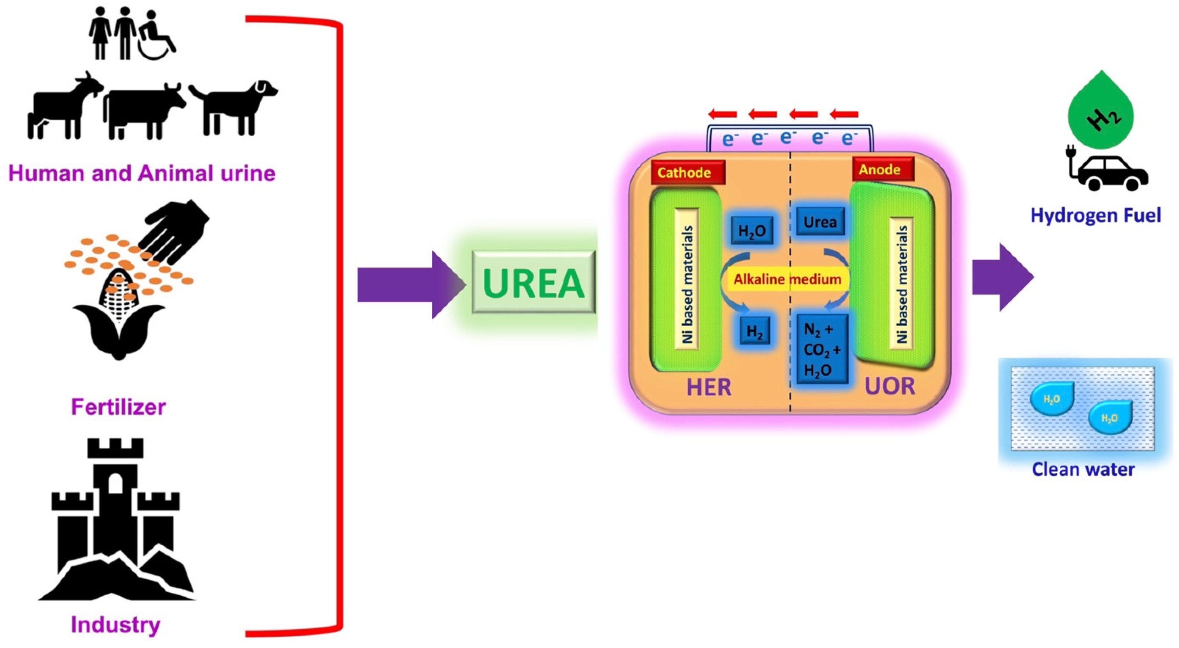
1. Background
2. Ni-Based Electrocatalysts for UOR Application
2.1. UOR Catalytic Mechanisms in Alkaline Medium
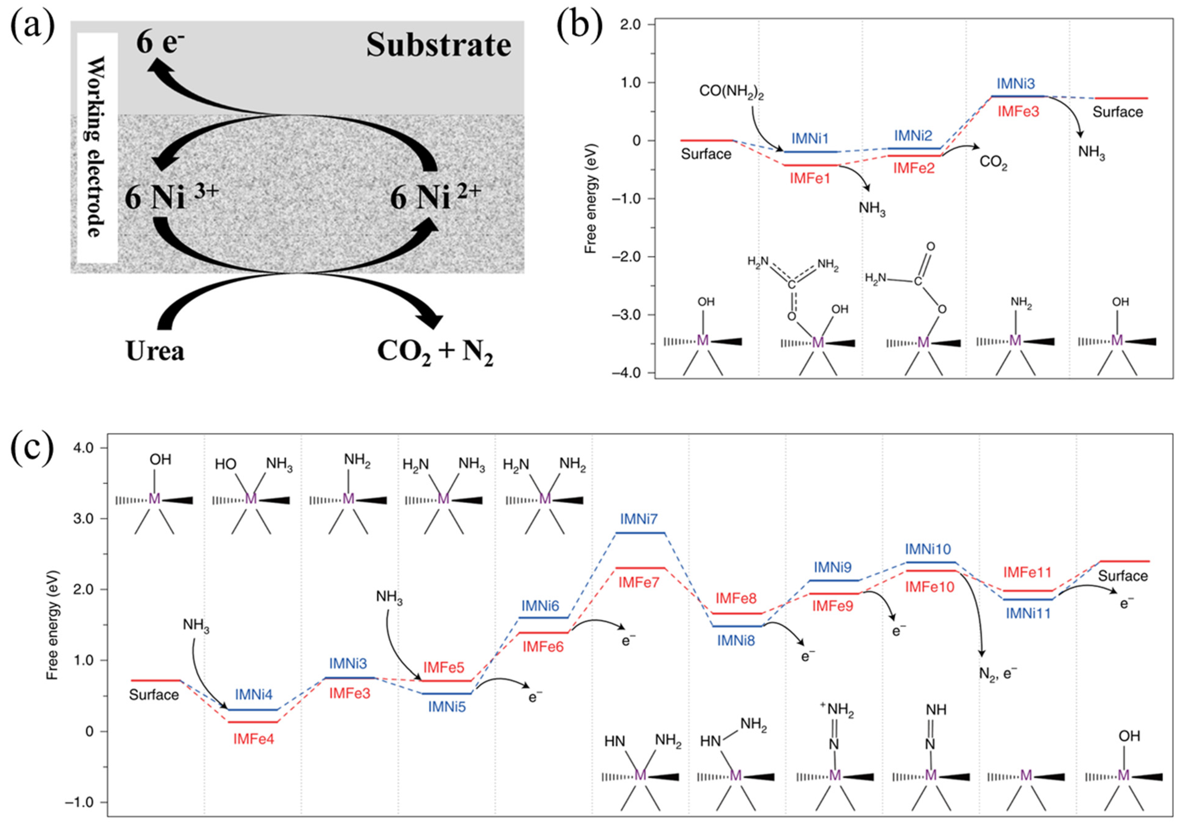
2.1.1. Direct Oxidation Mechanism for the NiOOH/Ni(OH)2 Catalyst
2.1.2. Indirect Oxidation Mechanism for the NiOOH/Ni(OH)2 Catalyst
2.1.3. Two-Stage Mechanism for the Ni2Fe(CN)6 Catalyst
2.2. Strategies for Developing Advanced UOR Electrocatalysts
2.2.1. Activating More Active Sites for the UOR
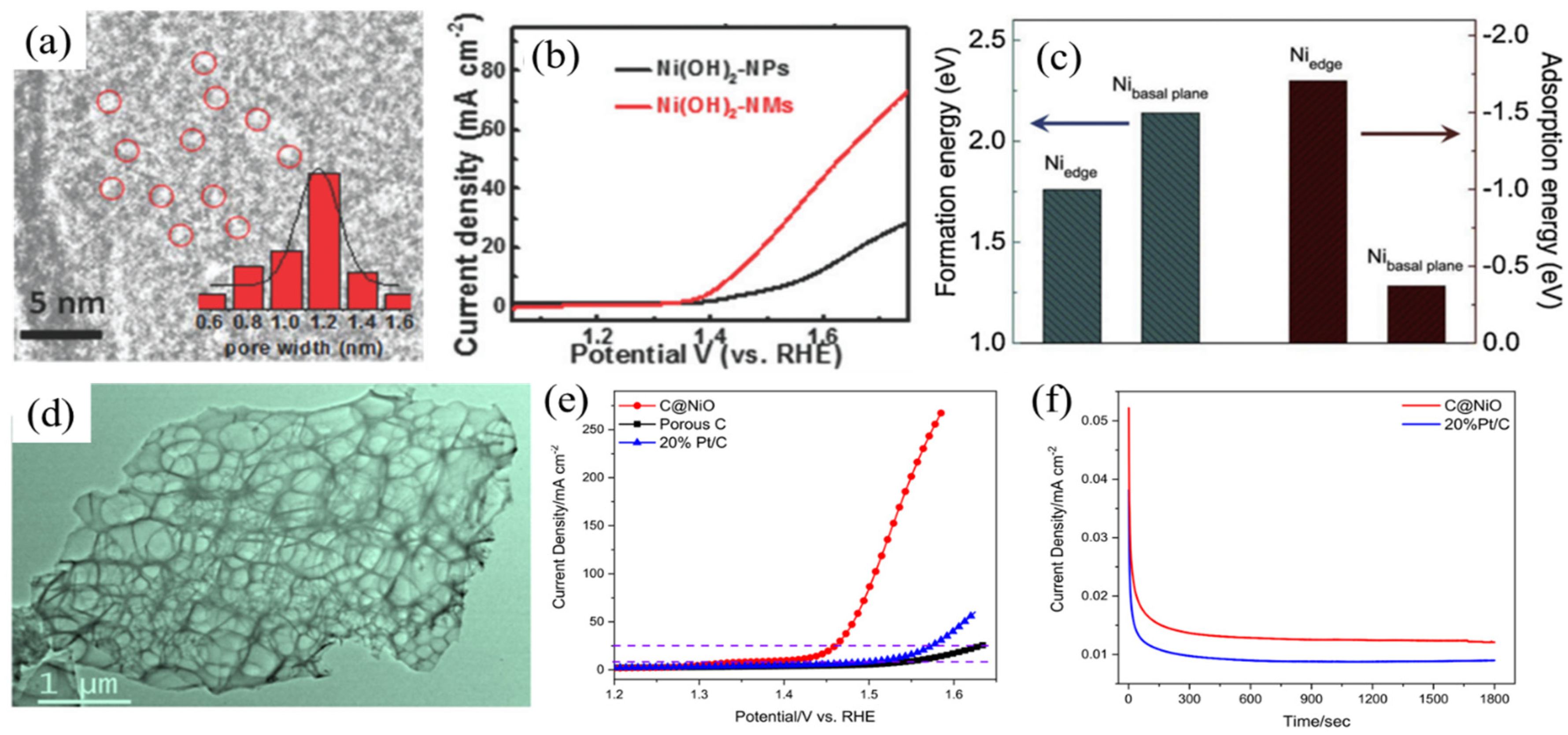
Nanostructured and Composite Materials
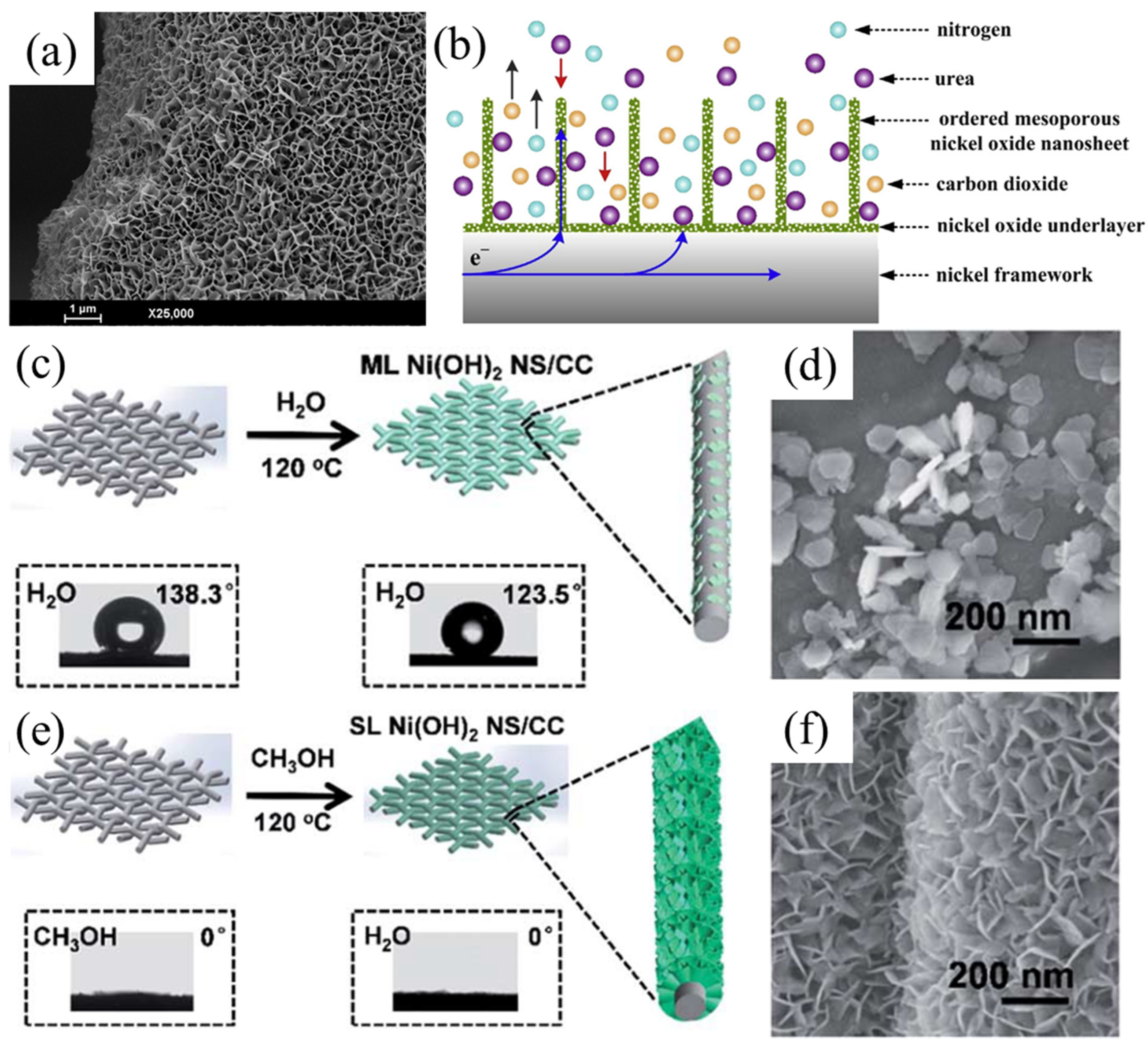
In Situ Growth on Highly Conductive Substrates
Heterostructured Materials

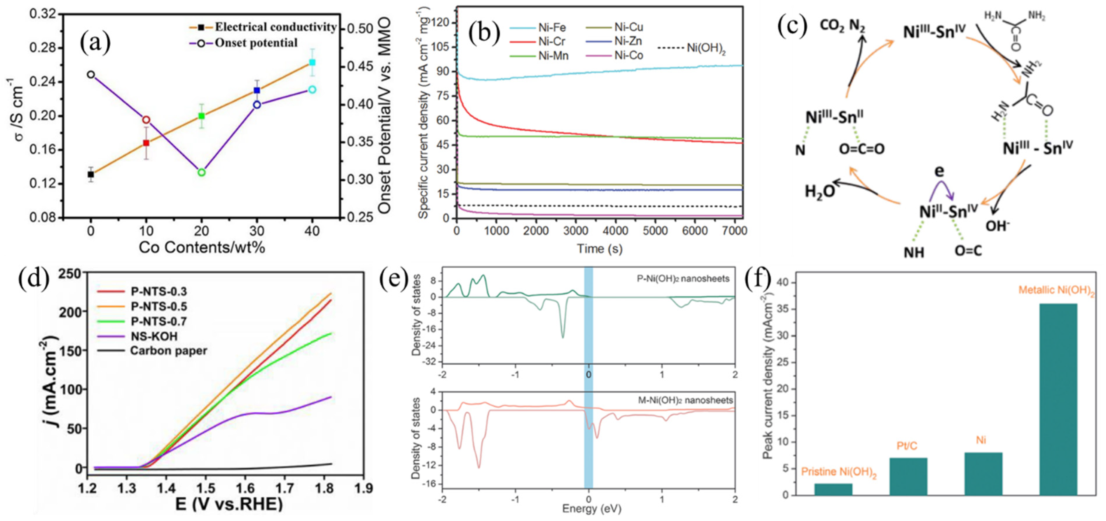
2.2.2. Enhancing Intrinsic UOR Catalytic Activity
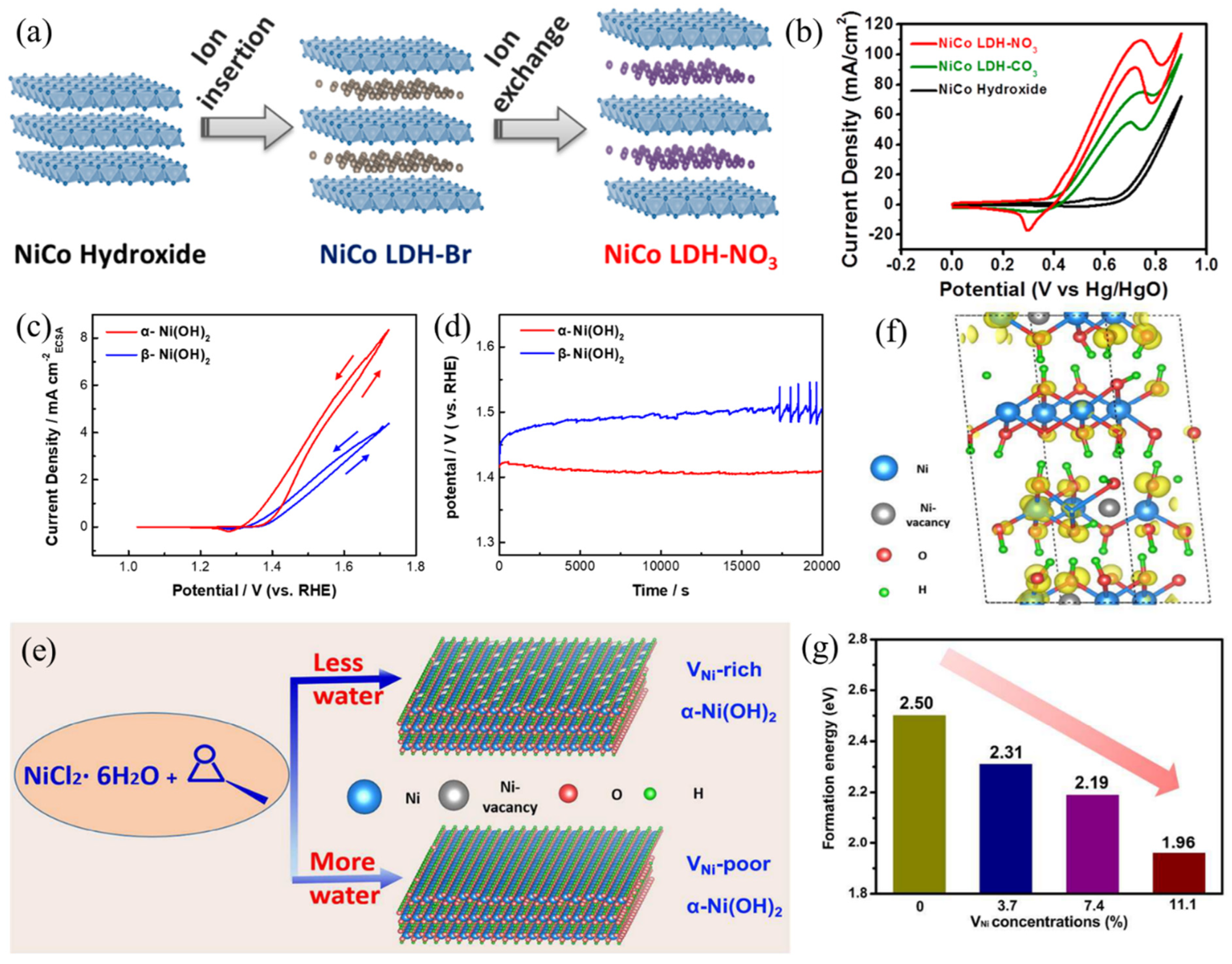
Crystallographic Effects of Ni(OH)2
Heteroatom Doping
3. Ni-Based Electrocatalysts for HER in Alkaline Medium
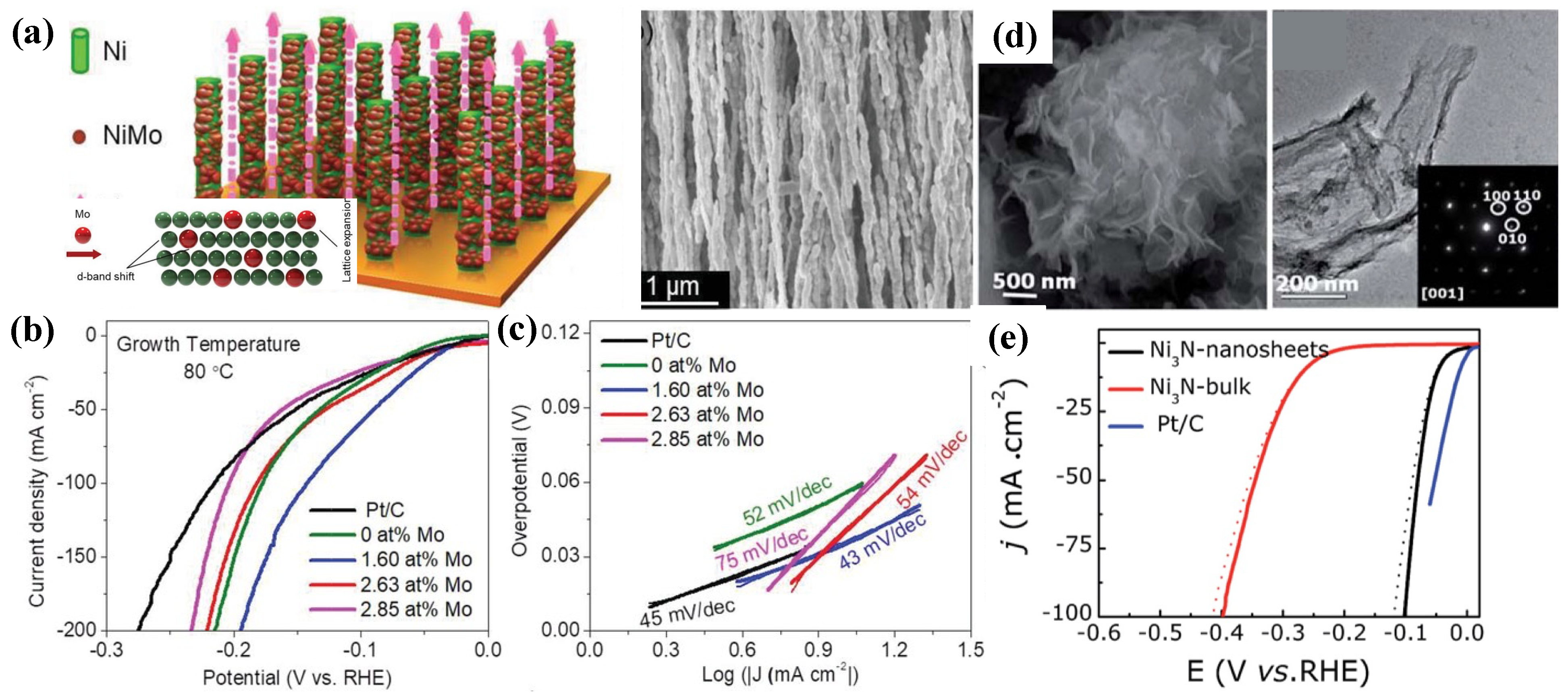
3.1. Metallic Ni-Based
3.2. Ni-Based Oxide/Hydroxide
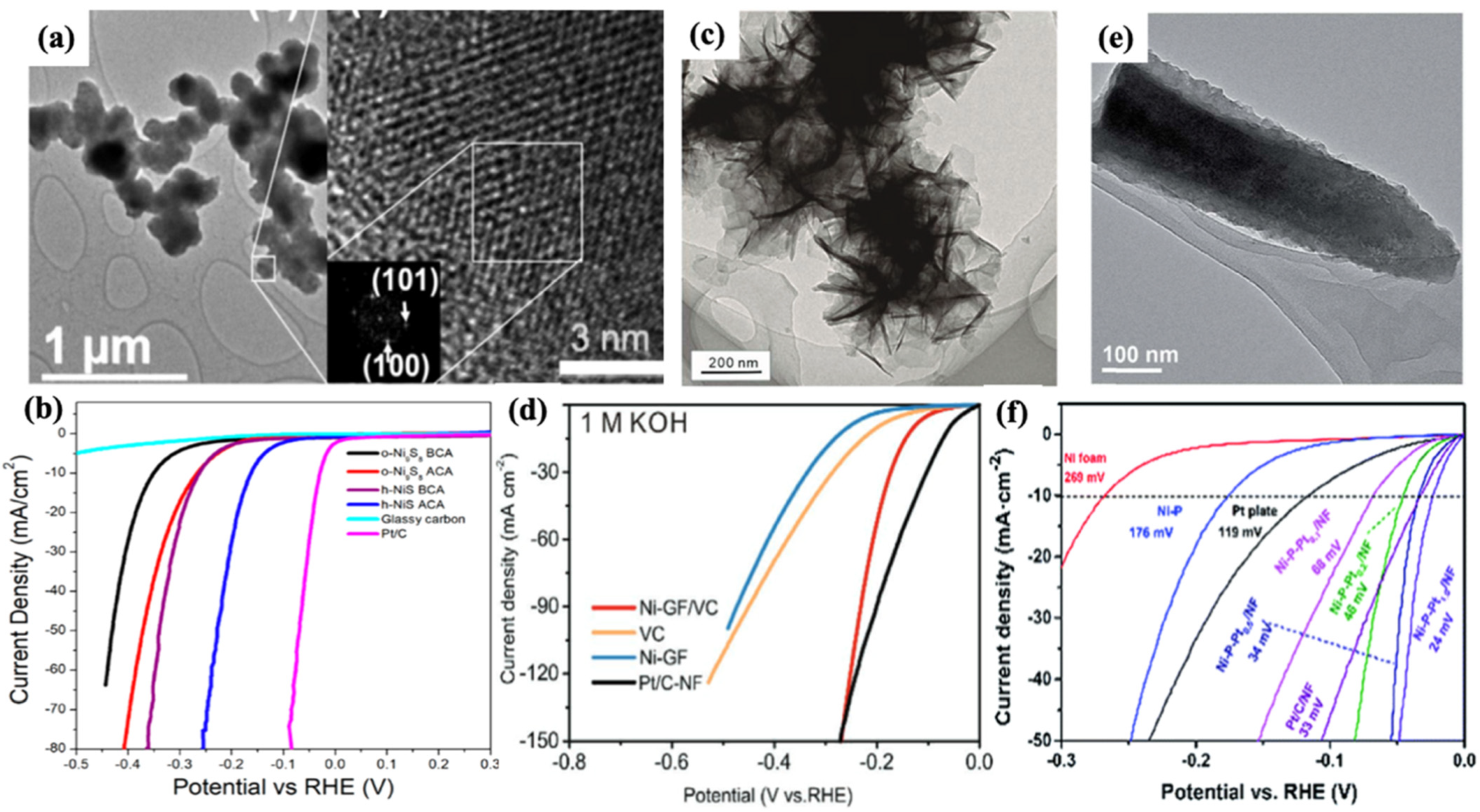
3.3. Ni-Based Dichalcogenides and Compounds
3.4. Ni-Based MOFs
3.5. Single-Atom Ni
3.6. Ni-Based Heterostructure
4. Bifunctional Electrocatalysts for the UOR and HER
4.1. Ni-Based Oxides/Hydroxides
4.2. Ni-Based Chalcogenides
4.3. Ni-Based MOFs and Nitrides
5. Summary and Outlook
- (1)
- Developing highly efficient UOR catalysts, in terms of boosted catalytic current, low overpotential and durable catalytic performance, is highly desirable. The majority of the prepared catalysts are nickel oxides and hydroxides at early stages, while nickel sulfides [115,116,117,118], selenides [62,63], phosphides [119,120] and nitrides [111] have shown appreciable UOR performance in recent years. In addition, Ni-based Prussian blue analogues [17] and perovskites [121] have also been revealed as promising candidates for the UOR. Thus, it is highly recommended to use the above-mentioned strategies to obtain diverse Ni−based catalysts. Scrutinizing these electrocatalysts by evaluating electrochemical performance and material/manufacturing cost is crucial for practical applications.
- (2)
- Compared to the OER, the UOR has the potential to reduce the amount of energy consumed for hydrogen production significantly. However, practically, the oxidation potential of the UOR (>1.2 V vs. RHE) is generally much higher than its theoretical value (0.37 V vs. RHE) due to high overpotential. The difference in oxidation potential between the OER and UOR should theoretically be over 0.8 V but is actually less than 0.2 V because of the high overpotential required for the UOR. At the same time, practically, the OER also requires high overpotential due to its sluggish kinetics. Therefore, the development of efficient electrocatalysts to reduce the overpotential of the UOR is more important for effective hydrogen production through urea electrolysis.
- (3)
- Electrochemical decomposition of urea involves multiple reaction steps and intermediates. Conducting in-depth studies on catalytic mechanisms is also important. So far, UOR mechanisms are only proposed for nickel oxide/hydroxide and Ni2Fe(CN)6-based catalysts. The roles of heteroatoms (such as S, Se, N, P and so on) and second/third metallic elements should be investigated. For defect engineering, the effects of structural defects (defect types and concentrations) on UOR catalytic activity should be discussed. Moreover, in situ characterizations are preferred to analyze the properties of catalysts while avoiding potential damage during post-treatment. DFT calculations can also provide valuable information for revealing the working principles of the prepared catalysts.
- (4)
- For the HER, the main challenge for further development is the improvement of the activities and stabilities of HER electrocatalysts. Additionally, the most successful HER electrocatalysts should possess porous structures at the nanoscale, with large electrochemically active surface areas for fast charge transfer reaction on the surface, rather than the well-defined nanostructure morphologies.
- (5)
- Recently, layered transition metal dichalcogenides MX2 were found to possess a hexagonal 2H structure and tetragonal 1T structure, with the stabilizing 1T structure being more significant due to its higher electric conductivity and electrocatalytic activity. On the other hand, due to the presence of abundant coordinatively unsaturated sites on the surface, amorphous materials have unique advantages toward the HER. Therefore, in future, attention should be given to the crystal structure and crystallinity of electrocatalysts for optimal HER electrocatalytic performance.
- (6)
- Bifunctional electrocatalysts of Ni-based chalcogenides are inclined to undergo self-construction in the alkaline medium, and in situ techniques such as Raman spectroscopy, X-ray diffraction spectroscopy and X-ray absorption spectroscopy are therefore required for exploring the reaction intermediates, which will be more useful for better understanding the reaction mechanisms.
- (7)
- Reducing manufacturing and material costs is also important for practical applications. Most of the Ni-based electrocatalysts are subjected to sophisticated preparation procedures, such as multi-step hydrothermal/solvothermal methods and/or high-temperature annealing conditions. Developing facile and energy saving methodologies for acquiring highly efficient electrocatalysts is highly recommended. For composite electrocatalysts, overall electrical conductivity can be effectively improved through the utilization of carbon supports such as graphene and carbon nanotubes. Nevertheless, using high-cost carbon-based materials would make the composite catalysts more economically unfavorable for practical applications.
- (8)
- To further improve the economic and environmental significance of urea electrolysis, natural urine/urea-bearing wastewater should be utilized as an electrolyte for urea electrolyzers instead of chemical reagent-based electrolytes.
- (9)
- Ultimately, to reduce costs and for convenient facilities, sunlight-powered photochemical urea electrolyzers should be developed for large-scale and commercial application of urea electrolysis.
Author Contributions
Funding
Institutional Review Board Statement
Informed Consent Statement
Data Availability Statement
Conflicts of Interest
References
- Kim, J.; Monllor-Satoca, D.; Choi, W. Simultaneous production of hydrogen with the degradation of organic pollutants using TiO2 photocatalyst modified with dual surface components. Energy Environ. Sci. 2012, 5, 7647. [Google Scholar] [CrossRef]
- Cook, T.R.; Dogutan, D.K.; Reece, S.Y.; Surendranath, Y.; Teets, T.S.; Nocera, D.G. Solar Energy Supply and Storage for the Legacy and Nonlegacy Worlds. Chem. Rev. 2010, 110, 6474. [Google Scholar] [CrossRef] [PubMed]
- Sun, X.; Ding, R. Recent progress with electrocatalysts for urea electrolysis in alkaline media for energy-saving hydrogen production. Catal. Sci. Technol. 2020, 10, 1567–1581. [Google Scholar] [CrossRef]
- Zhang, L.; Wang, L.; Lin, H.; Liu, Y.; Ye, J.; Wen, Y.; Chen, A.; Wang, L.; Ni, F.; Zhou, Z.; et al. A lattice-oxygen-involved reaction pathway to boost urea oxidation. Angew. Chem. 2019, 131, 16976–16981. [Google Scholar] [CrossRef]
- Lhermitte, C.R.; Sivula, K. Alternative oxidation reactions for solar-driven fuel production. ACS Catal. 2019, 9, 2007–2017. [Google Scholar] [CrossRef]
- Cha, H.G.; Choi, K.S. Combined biomass valorization and hydrogen production in a photoelectrochemical cell. Nat. Chem. 2015, 7, 328–333. [Google Scholar] [CrossRef]
- Gnana kumar, G.; Farithkhan, A.; Manthiram, A. Direct urea fuel cells: Recent progress and critical challenges of urea oxidation electrocatalysis. Adv. Energy Sustain. Res. 2020, 1, 2000015. [Google Scholar] [CrossRef]
- Tang, C.; Zhao, Z.L.; Chen, J.; Li, B.; Chen, L.; Li, C.M. Se-Ni(OH)2-shelled vertically oriented NiSe nanowires as a superior electrocatalyst toward urea oxidation reaction of fuel cells. Electrochim. Acta 2017, 248, 243–249. [Google Scholar] [CrossRef]
- Jin, H.; Joo, J.; Chaudhari, N.K.; Choi, S.I.; Lee, K. Recent progress in bifunctional electrocatalysts for overall water splitting under acidic conditions. ChemElectroChem 2019, 6, 3244–3253. [Google Scholar] [CrossRef]
- Climent, V.; Rodes, A.; Orts, J.M.; Aldaz, A.; Feliu, J.M. Urea adsorption on Pt (111) electrodes. J. Electroanal. Chem. 1999, 461, 65–75. [Google Scholar] [CrossRef]
- Suárez, D.; Díaz, N.; Merz, K.M. Ureases: Quantum chemical calculations on cluster models. J. Am. Chem. Soc. 2003, 125, 15324–15337. [Google Scholar] [CrossRef] [PubMed]
- Boggs, B.K.; King, R.L.; Botte, G.G. Urea electrolysis: Direct hydrogen production from urine. Chem. Commun. 2009, 32, 4859–4861. [Google Scholar] [CrossRef] [PubMed]
- Vedharathinam, V.; Botte, G.G. Understanding the Electro-Catalytic Oxidation Mechanism of Urea on Nickel Electrodes in Alkaline Medium. Electrochim. Acta 2012, 81, 292–300. [Google Scholar] [CrossRef]
- Daramola, D.A.; Singh, D.; Botte, G.G. Dissociation Rates of Urea in the Presence of NiOOH Catalyst A DFT Analysis. J. Phys. Chem. 2010, 114, 11513–11521. [Google Scholar] [CrossRef]
- Vedharathinam, V.; Botte, G.G. Direct Evidence of the Mechanism for the Electro-Oxidation of Urea on Ni(OH)2 Catalyst in Alkaline Medium. Electrochim. Acta 2013, 108, 660–665. [Google Scholar] [CrossRef]
- Wang, D.; Botte, G.G. In Situ X-Ray diffraction study of urea electrolysis on nickel catalysts. ECS Electrochem. Lett. 2014, 3, H29–H32. [Google Scholar] [CrossRef]
- Geng, S.-K.; Zheng, Y.; Li, S.-Q.; Su, H.; Zhao, X.; Hu, J.; Shu, H.-B.; Jaroniec, M.; Chen, P.; Liu, Q.-H.; et al. Nickel Ferrocyanide as a High-Performance Urea Oxidation Electrocatalyst. Nat. Energy 2021, 6, 904–912. [Google Scholar] [CrossRef]
- Singh, R.K.; Rajavelu, K.; Montag, M.; Schechter, A. Advances in Catalytic Electrooxidation of Urea: A Review. Energy Technol. 2021, 9, 2100017. [Google Scholar] [CrossRef]
- Singh, R.K.; Subramanian, P.; Schechter, A. Enhanced Urea Activity of Oxidation on Nickel-Deposited Tin Dendrites. ChemElectroChem 2017, 4, 1037–1043. [Google Scholar] [CrossRef]
- Guo, F.; Ye, K.; Du, M.; Huang, X.; Cheng, K.; Wang, G.; Cao, D. Electrochemical Impedance Analysis of Urea Electro-Oxidation Mechanism on Nickel Catalyst in Alkaline Medium. Electrochim. Acta 2016, 210, 474–482. [Google Scholar] [CrossRef]
- Hu, X.; Zhu, J.; Li, J.; Wu, Q. Urea Electrooxidation: Current Development and Understanding of Ni-Based Catalysts. ChemElectroChem 2020, 7, 3211–3228. [Google Scholar] [CrossRef]
- Li, J.; Wang, S.; Chang, J.; Feng, L. A Review of Ni Based Powder Catalyst for Urea Oxidation in Assisting Water Splitting Reaction. Adv. Powder Technol. 2022, 1, 100030. [Google Scholar] [CrossRef]
- Ma, Y.; Ma, C.; Wang, Y.; Wang, K. Advanced Nickel-Based Catalysts for Urea Oxidation Reaction: Challenges and Developments. Catalysts 2022, 12, 337. [Google Scholar] [CrossRef]
- Ye, K.; Wang, G.; Cao, D.; Wang, G. Recent Advances in the Electro-Oxidation of Urea for Direct Urea Fuel Cell and Urea Electrolysis. Top. Curr. Chem. 2018, 376, 42. [Google Scholar] [CrossRef]
- Zhu, B.; Liang, Z.; Zou, R. Designing Advanced Catalysts for Energy Conversion Based on Urea Oxidation Reaction. Small 2020, 16, 1906133. [Google Scholar] [CrossRef]
- Sayed, E.T.; Abdelkareem, M.A.; Bahaa, A.; Eisa, T.; Alawadhi, H.; Al-Asheh, S.; Chae, K.-J.; Olabi, A.G. Synthesis and Performance Evaluation of Various Metal Chalcogenides as Active Anodes for Direct Urea Fuel Cells. Renew. Sustain. Energy Rev. 2021, 150, 111470. [Google Scholar] [CrossRef]
- Wang, D.; Yan, W.; Botte, G.G. Exfoliated Nickel Hydroxide Nanosheets for Urea Electrolysis. Electrochem. Commun. 2011, 13, 1135–1138. [Google Scholar] [CrossRef]
- Ding, Y.; Li, Y.; Xue, Y.; Miao, B.; Li, S.; Jiang, Y.; Liu, X.; Chen, Y. Atomically Thick Ni(OH)2 Nanomeshes for Urea Electrooxidation. Nanoscale 2019, 11, 1058–1064. [Google Scholar] [CrossRef]
- Ye, K.; Zhang, H.; Zhao, L.; Huang, X.; Cheng, K.; Wang, G.; Cao, D. Facile Preparation of Three-Dimensional Ni(OH)2/Ni Foam Anode with Low Cost and Its Application in a Direct Urea Fuel Cell. New J. Chem. 2016, 40, 8673–8680. [Google Scholar] [CrossRef]
- Yang, W.; Yang, X.; Hou, C.; Li, B.; Gao, H.; Lin, J.; Luo, X. Rapid Room-Temperature Fabrication of Ultrathin Ni(OH)2 Nanoflakes with Abundant Edge Sites for Efficient Urea Oxidation. Appl. Catal. B 2019, 259, 118020. [Google Scholar] [CrossRef]
- Cao, Z.; Mao, H.; Guo, X.; Sun, D.; Sun, Z.; Wang, B.; Zhang, Y.; Song, X.-M. Hierarchical Ni(OH)2/Polypyrrole/Graphene Oxide Nanosheets as Excellent Electrocatalysts for the Oxidation of Urea. ACS Sustain. Chem. Eng. 2018, 6, 15570–15581. [Google Scholar] [CrossRef]
- Lu, S.; Hummel, M.; Gu, Z.; Wang, Y.; Wang, K.; Pathak, R.; Zhou, Y.; Jia, H.; Qi, X.; Zhao, X.; et al. Highly Efficient Urea Oxidation via Nesting Nano-Nickel Oxide in Eggshell Membrane-Derived Carbon. ACS Sustain. Chem. Eng. 2021, 9, 1703–1713. [Google Scholar] [CrossRef]
- Kim, J.; Lee, J.; Tak, Y. Relationship between carbon corrosion and positive electrode potential in a proton-exchange membrane fuel cell during start/stop operation. J. Power Source 2009, 192, 674–678. [Google Scholar] [CrossRef]
- Peng, Y.-Y.; Wu, M.-S. Flower-Like Manganese Oxide with Intercalated Nickel Ions (Ni3+) as a Catalytic Electrode Material for Urea Oxidation. Electrochim. Acta 2022, 410, 140022. [Google Scholar] [CrossRef]
- Wu, M.-S.; Lin, G.-W.; Yang, R.-S. Hydrothermal Growth of Vertically-Aligned Ordered Mesoporous Nickel Oxide Nanosheets on Three-Dimensional Nickel Framework for Electrocatalytic Oxidation of Urea in Alkaline Medium. J. Power Source 2014, 272, 711–718. [Google Scholar] [CrossRef]
- Zhan, S.; Zhou, Z.; Liu, M.; Jiao, Y.; Wang, H. 3D NiO Nanowalls Grown on Ni Foam for Highly Efficient Electro-Oxidation of Urea. Catal. Today 2019, 327, 398–404. [Google Scholar] [CrossRef]
- Lin, C.; Gao, Z.; Zhang, F.; Yang, J.; Liu, B.; Jin, J. In Situ Growth of Single-Layered α-Ni(OH)2 Nanosheets on a Carbon Cloth for Highly Efficient Electrocatalytic Oxidation of Urea. J. Mater. Chem. A 2018, 6, 13867–13873. [Google Scholar] [CrossRef]
- Yang, Y.; Zhang, K.; Lin, H.; Li, X.; Chan, H.C.; Yang, L.; Gao, Q. MoS2–Ni3S2 Heteronanorods as Efficient and Stable Bifunctional Electrocatalysts for Overall Water Splitting. ACS Catal. 2017, 7, 2357–2366. [Google Scholar] [CrossRef]
- An, L.; Feng, J.; Zhang, Y.; Wang, R.; Liu, H.; Wang, G.-C.; Cheng, F.; Xi, P. Epitaxial Heterogeneous Interfaces on N-NiMoO4/NiS2 Nanowires/Nanosheets to Boost Hydrogen and Oxygen Production for Overall Water Splitting. Adv. Funct. Mater. 2019, 29, 1805298. [Google Scholar] [CrossRef]
- Xiao, C.; Li, S.; Zhang, X.; MacFarlane, D.R. MnO2/MnCo2O4/Ni Heterostructure with Quadruple Hierarchy: A Bifunctional Electrode Architecture for Overall Urea Oxidation. J. Mater. Chem. A 2017, 5, 7825–7832. [Google Scholar] [CrossRef]
- Qian, G.; Chen, J.; Luo, L.; Zhang, H.; Chen, W.; Gao, Z.; Yin, S.; Tsiakaras, P. Novel Bifunctional V2O3 Nanosheets Coupled with N-Doped-Carbon Encapsulated Ni Heterostructure for Enhanced Electrocatalytic Oxidation of Urea-Rich Wastewater. ACS Appl. Mater. Interface 2020, 12, 38061–38069. [Google Scholar] [CrossRef] [PubMed]
- Sha, L.; Liu, T.; Ye, K.; Zhu, K.; Yan, J.; Yin, J.; Wang, G.; Cao, D. A Heterogeneous Interface on NiS@Ni3S2/NiMoO4 Heterostructures for Efficient Urea Electrolysis. J. Mater. Chem. A 2020, 8, 18055–18063. [Google Scholar] [CrossRef]
- Liu, J.; Wang, Y.; Liao, Y.; Wu, C.; Yan, Y.; Xie, H.; Chen, Y. Heterostructured Ni3S2-Ni3P/NF as a Bifunctional Catalyst for Overall Urea-Water Electrolysis for Hydrogen Generation. ACS Appl. Mater. Interface 2021, 13, 26948–26959. [Google Scholar] [CrossRef] [PubMed]
- Li, F.; Chen, J.; Zhang, D.; Fu, W.F.; Chen, Y.; Wen, Z.; Lv, X.J. Heteroporous MoS2/Ni3S2 Towards Superior Electrocatalytic Overall Urea Splitting. Chem. Commun. 2018, 54, 5181–5184. [Google Scholar] [CrossRef]
- Xu, Q.; Yu, T.; Chen, J.; Qian, G.; Song, H.; Luo, L.; Chen, Y.; Liu, T.; Wang, Y.; Yin, S. Coupling Interface Constructions of FeNi3-MoO2 Heterostructures for Efficient Urea Oxidation and Hydrogen Evolution Reaction. ACS. Appl. Mater. Interface 2021, 13, 16355–16363. [Google Scholar] [CrossRef]
- Zeng, M.; Wu, J.; Li, Z.; Wu, H.; Wang, J.; Wang, H.; He, L.; Yang, X. Interlayer Effect in NiCo Layered Double Hydroxide for Promoted Electrocatalytic Urea Oxidation. ACS Sustain. Chem. Eng. 2019, 7, 4777–4783. [Google Scholar] [CrossRef]
- Wu, T.H.; Hou, B.W. Superior Catalytic Activity of α-Ni(OH)2 for Urea Electrolysis. Catal. Sci. Technol. 2021, 11, 4294–4300. [Google Scholar] [CrossRef]
- He, Q.; Wan, Y.; Jiang, H.; Pan, Z.; Wu, C.; Wang, M.; Wu, X.; Ye, B.; Ajayan, P.M.; Song, L. Nickel Vacancies Boost Reconstruction in Nickel Hydroxide Electrocatalyst. ACS Energy Lett. 2018, 3, 1373–1380. [Google Scholar] [CrossRef]
- Yan, W.; Wang, D.; Botte, G.G. Nickel and Cobalt Bimetallic Hydroxide Catalysts for Urea Electro-Oxidation. Electrochim. Acta 2012, 61, 25–30. [Google Scholar] [CrossRef]
- Singh, R.K.; Schechter, A. Electroactivity of NiCr Catalysts for Urea Oxidation in Alkaline Electrolyte. ChemCatChem 2017, 9, 3374–3379. [Google Scholar] [CrossRef]
- Barakat, N.A.M.; Alajami, M.; Al Haj, Y.; Obaid, M.; Al-Meer, S. Enhanced Onset Potential NiMn-Decorated Activated Carbon as Effective and Applicable Anode in Urea Fuel Cells. Catal. Commun. 2017, 97, 32–36. [Google Scholar] [CrossRef]
- Xie, J.; Qu, H.; Lei, F.; Peng, X.; Liu, W.; Gao, L.; Hao, P.; Cui, G.; Tang, B. Partially Amorphous Nickel-Iron Layered Double Hydroxide Nanosheet Arrays for Robust Bifunctional Electrocatalysis. J. Mater. Chem. A 2018, 6, 16121–16129. [Google Scholar] [CrossRef]
- Mohamed, I.M.A.; Yasin, A.S.; Barakat, N.A.M.; Song, S.A.; Lee, H.E.; Kim, S.S. Electrocatalytic Behavior of a Nanocomposite of Ni/Pd Supported by Carbonized PVA Nanofibers Towards Formic Acid, Ethanol and Urea Oxidation: A Physicochemical and Electro-Analysis Study. Appl. Surf. Sci. 2018, 435, 122–129. [Google Scholar] [CrossRef]
- Xu, W.; Zhang, H.; Li, G.; Wu, Z. Nickel-Cobalt Bimetallic Anode Catalysts for Direct Urea Fuel Cell. Sci. Rep. 2014, 4, 5863. [Google Scholar] [CrossRef] [PubMed]
- Xu, W.; Du, D.; Lan, R.; Humphreys, J.; Wu, Z.; Tao, S. Highly active Ni–Fe double hydroxides as anode catalysts for electrooxidation of urea. New J. Chem. 2017, 41, 4190–4196. [Google Scholar] [CrossRef]
- Mohamed, I.M.A.; Liu, C. Chemical Design of Novel Electrospun CoNi/Cr Nanoparticles Encapsulated in C-Nanofibers as Highly Efficient Material for Urea Oxidation in Alkaline Media. Appl. Surf. Sci. 2019, 475, 532–541. [Google Scholar] [CrossRef]
- Ji, Z.; Liu, J.; Deng, Y.; Zhang, S.; Zhang, Z.; Du, P.; Zhao, Y.; Lu, X. Accurate Synergy Effect of Ni–Sn Dual Active Sites Enhances Electrocatalytic Oxidation of Urea for Hydrogen Evolution in Alkaline Medium. J. Mater. Chem. A 2020, 8, 14680–14689. [Google Scholar] [CrossRef]
- Zhu, X.; Dou, X.; Dai, J.; An, X.; Guo, Y.; Zhang, L.; Tao, S.; Zhao, J.; Chu, W.; Zeng, X.C.; et al. Metallic Nickel Hydroxide Nanosheets Give Superior Electrocatalytic Oxidation of Urea for Fuel Cells. Angew. Chem. Int. Ed. 2016, 55, 12465–12469. [Google Scholar] [CrossRef]
- Zhu, W.; Yue, Z.; Zhang, W.; Hu, N.; Luo, Z.; Ren, M.; Xu, Z.; Wei, Z.; Suo, Y.; Wang, J. Wet-Chemistry Topotactic Synthesis of Bimetallic Iron-Nickel Sulfide Nanoarrays: An Advanced and Versatile Catalyst for Energy Efficient Overall Water and Urea Electrolysis. J. Mater. Chem. A 2018, 6, 4346–4353. [Google Scholar] [CrossRef]
- Wu, T.H.; Lin, Y.C.; Hou, B.W.; Liang, W.Y. Nanostructured β-NiS Catalyst for Enhanced and Stable Electro-Oxidation of Urea. Catalysts 2020, 10, 1280. [Google Scholar] [CrossRef]
- Zhong, M.; Li, W.; Wang, C.; Lu, X. Synthesis of Hierarchical Nickel Sulfide Nanotubes for Highly Efficient Electrocatalytic Urea Oxidation. Appl. Surf. Sci. 2022, 575, 151708. [Google Scholar] [CrossRef]
- Xiong, P.; Ao, X.; Chen, J.; Li, J.-G.; Lv, L.; Li, Z.; Zondode, M.; Xue, X.; Lan, Y.; Wang, C. Nickel Diselenide Nanoflakes Give Superior Urea Electrocatalytic Conversion. Electrochim. Acta 2019, 297, 833–841. [Google Scholar] [CrossRef]
- Ni, S.; Qu, H.; Xu, Z.; Zhu, X.; Xing, H.; Wang, L.; Yu, J.; Liu, H.; Chen, C.; Yang, L. Interfacial Engineering of the NiSe2/FeSe2 p-p Heterojunction for Promoting Oxygen Evolution Reaction and Electrocatalytic Urea Oxidation. Appl. Catal. B 2021, 299, 120638. [Google Scholar] [CrossRef]
- Zhang, Q.; Kazim, F.M.D.; Ma, S.; Qu, K.; Li, M.; Wang, Y.; Hu, H.; Cai, W.; Yang, Z. Nitrogen Dopants in Nickel Nanoparticles Embedded Carbon Nanotubes Promote Overall Urea Oxidation. Appl. Catal. B 2021, 280, 119436. [Google Scholar] [CrossRef]
- Vij, V.; Sultan, S.; Harzandi, A.M.; Meena, A.; Tiwari, J.N.; Lee, W.-G.; Yoon, T.; Kim, K.S. Nickel-Based Electrocatalysts for Energy-Related Applications: Oxygen Reduction, Oxygen Evolution, and Hydrogen Evolution Reactions. ACS Catal. 2017, 7, 7196. [Google Scholar] [CrossRef]
- Nairan, A.; Zou, P.; Liang, C.; Liu, J.; Wu, D.; Liu, P.; Yang, C. NiMo Solid Solution Nanowire Array Electrodes for Highly Efficient Hydrogen Evolution Reaction. Adv. Funct. Mater. 2019, 29, 1903747. [Google Scholar] [CrossRef]
- Gao, D.; Zhang, J.; Wang, T.; Xiao, W.; Tao, K.; Xue, D.; Ding, J. Metallic Ni3N nanosheets with exposed active surface sites for efficient hydrogen evolution. J. Mater. Chem. A 2016, 4, 17363. [Google Scholar] [CrossRef]
- Wu, F.; Ou, G.; Yang, J.; Li, H.; Gao, Y.; Chen, F.; Wang, Y.; Shi, Y. Bifunctional nickel oxide-based nanosheets for highly efficient overall urea splitting. Chem. Commun. 2019, 55, 6555. [Google Scholar] [CrossRef]
- Suryanto, B.H.R.; Wang, Y.; Hocking, R.K.; Adamson, W.; Zhao, C. Overall electrochemical splitting of water at the heterogeneous interface of nickel and iron oxide. Nat. Commun. 2019, 10, 5599. [Google Scholar] [CrossRef]
- Zhai, P.; Xia, M.; Wu, Y.; Zhang, G.; Gao, J.; Zhang, B.; Cao, S.; Zhang, Y.; Li, Z.; Fan, Z.; et al. Engineering single-atomic ruthenium catalytic sites on defective nickel-iron layered double hydroxide for overall water splitting. Nat. Commun. 2021, 12, 4587. [Google Scholar] [CrossRef]
- Yang, C.; Zhao, R.; Xiang, H.; Wu, J.; Zhong, W.; Li, W.; Zhang, Q.; Yang, N.; Li, X. Ni-Activated Transition Metal Carbides for Efficient Hydrogen Evolution in Acidic and Alkaline Solutions. Adv. Energy Mater. 2020, 10, 2002260. [Google Scholar] [CrossRef]
- Popczun, E.J.; McKone, J.R.; Read, C.G.; Biacchi, A.J.; Wiltrout, A.M.; Lewis, N.S.; Schaak, R.E. Nanostructured Nickel Phosphide as an Electrocatalyst for the Hydrogen Evolution Reaction. J. Am. Chem. Soc. 2013, 135, 9267. [Google Scholar] [CrossRef]
- da Silva, M.G.S.; Leite, C.M.; Cordeiro, M.A.L.; Mastelaro, V.R.; Leite, E.R. One-Step Synthesis of Nickel Sulfides and Their Electrocatalytic Activities for Hydrogen Evolution Reaction: A Case Study of Crystalline h-NiS and o-Ni9S8 Nanoparticles. ACS Appl. Energy Mater. 2020, 3, 9498. [Google Scholar] [CrossRef]
- Laursen, A.B.; Patraju, K.R.; Whitaker, M.J.; Retuerto, M.; Sarkar, T.; Yao, N.; Ramanujachary, K.V.; Greenblatt, M.; Dismukes, G.C. Nanocrystalline Ni5P4: A hydrogen evolution electrocatalyst of exceptional efficiency in both alkaline and acidic media. Energy Environ. Sci. 2015, 8, 1027. [Google Scholar] [CrossRef]
- Cao, Z.; Chen, Q.; Zhang, J.; Li, H.; Jiang, Y.; Shen, S.; Fu, G.; Lu, B.-A.; Xie, Z.; Zheng, L. Platinum-nickel alloy excavated nano-multipods with hexagonal close-packed structure and superior activity towards hydrogen evolution reaction. Nat. Commun. 2017, 8, 15131. [Google Scholar] [CrossRef]
- Xia, J.; Dhaka, K.; Volokh, M.; Peng, G.; Wu, Z.; Fu, Y.; Caspary Toroker, M.; Wang, X.; Shalom, M. Nickel phosphide decorated with trace amount of platinum as an efficient electrocatalyst for the alkaline hydrogen evolution reaction. Sustain. Energy Fuel. 2019, 3, 2006. [Google Scholar] [CrossRef]
- Xu, X.; Nosheen, F.; Wang, X. Ni-Decorated Molybdenum Carbide Hollow Structure Derived from Carbon-Coated Metal-Organic Framework for Electrocatalytic Hydrogen Evolution Reaction. Chem. Mater. 2016, 28, 6313. [Google Scholar] [CrossRef]
- Wang, T.; Zhou, Q.; Wang, X.; Zheng, J.; Li, X. MOF-derived surface modified Ni nanoparticles as an efficient catalyst for the hydrogen evolution reaction. J. Mater. Chem. A 2015, 3, 16435. [Google Scholar] [CrossRef]
- Duan, J.; Chen, S.; Zhao, C. Ultrathin metal-organic framework array for efficient electrocatalytic water splitting. Nat. Commun. 2017, 8, 15341. [Google Scholar] [CrossRef]
- Campbell, C.T. Electronic perturbations. Nat. Chem. 2012, 4, 597. [Google Scholar] [CrossRef]
- Wang, Q.; Zhao, Z.L.; Dong, S.; He, D.; Lawrence, M.J.; Han, S.; Cai, C.; Xiang, S.; Rodriguez, P.; Xiang, B.; et al. Design of active nickel single-atom decorated MoS2 as a pH-universal catalyst for hydrogen evolution reaction. Nano Energy 2018, 53, 458. [Google Scholar] [CrossRef]
- Lai, W.; Ge, L.; Li, H.; Deng, Y.; Xu, B.; Ouyang, B.; Kan, E. In situ Raman spectroscopic study towards the growth and excellent HER catalysis of Ni/Ni(OH)2 heterostructure. Int. J. Hydrogen Energy 2021, 46, 26861. [Google Scholar] [CrossRef]
- Zhou, M.; Weng, Q.; Popov, Z.I.; Yang, Y.; Antipina, L.Y.; Sorokin, P.B.; Wang, X.; Bando, Y.; Golberg, D. Construction of Polarized Carbon-Nickel Catalytic Surfaces for Potent, Durable, and Economic Hydrogen Evolution Reactions. ACS Nano 2018, 12, 4148. [Google Scholar] [CrossRef]
- Park, S.; Shao, Y.; Liu, J.; Wang, Y. Oxygen Electrocatalysts for Water Electrolyzers and Reversible Fuel Cells: Status and Perspective. Energy Environ. Sci. 2012, 5, 9331. [Google Scholar] [CrossRef]
- Zeng, M.; Li, Y. Recent Advances in Heterogeneous Electrocatalysts for the Hydrogen Evolution Reaction. J. Mater. Chem. A 2015, 3, 14942–14962. [Google Scholar] [CrossRef]
- Jiang, Y.; Gao, S.; Liu, J.; Xu, G.; Jia, Q.; Chen, F.; Song, X. Ti-Mesh supported porous CoS2 nanosheet self-interconnected networks with high oxidation states for efficient hydrogen production via urea electrolysis. Nanoscale 2020, 12, 11573–11581. [Google Scholar] [CrossRef] [PubMed]
- Lv, L.; Li, Z.; Wan, H.; Wang, C. Achieving low-energy consumption water-to-hydrogen conversion via urea electrolysis over a bifunctional electrode of hierarchical cuprous sulfide@nickel selenide nanoarrays. J. Colloid Interface Sci. 2021, 592, 13–21. [Google Scholar] [CrossRef]
- Yu, Z.Y.; Lang, C.C.; Gao, M.R.; Chen, Y.; Fu, Q.Q.; Duan, Y.; Yu, S.H. Ni–Mo–O nanorod-derived composite catalysts for efficient alkaline water-to-hydrogen conversion via urea electrolysis. Energy Environ. Sci. 2018, 11, 1890–1897. [Google Scholar] [CrossRef]
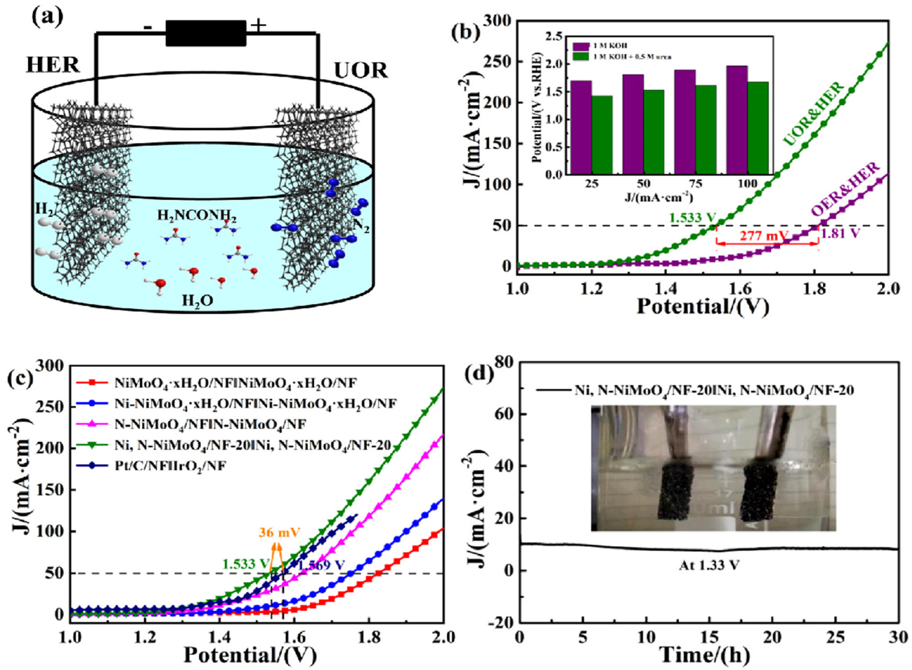
- Wang, T.; Wu, H.; Feng, C.; Ding, Y.; Mei, H. Ni, N-codoped NiMoO4 grown on 3D nickel foam as bifunctional electrocatalysts for hydrogen production in urea-water electrolysis. Electrochim. Acta 2021, 391, 138931. [Google Scholar] [CrossRef]
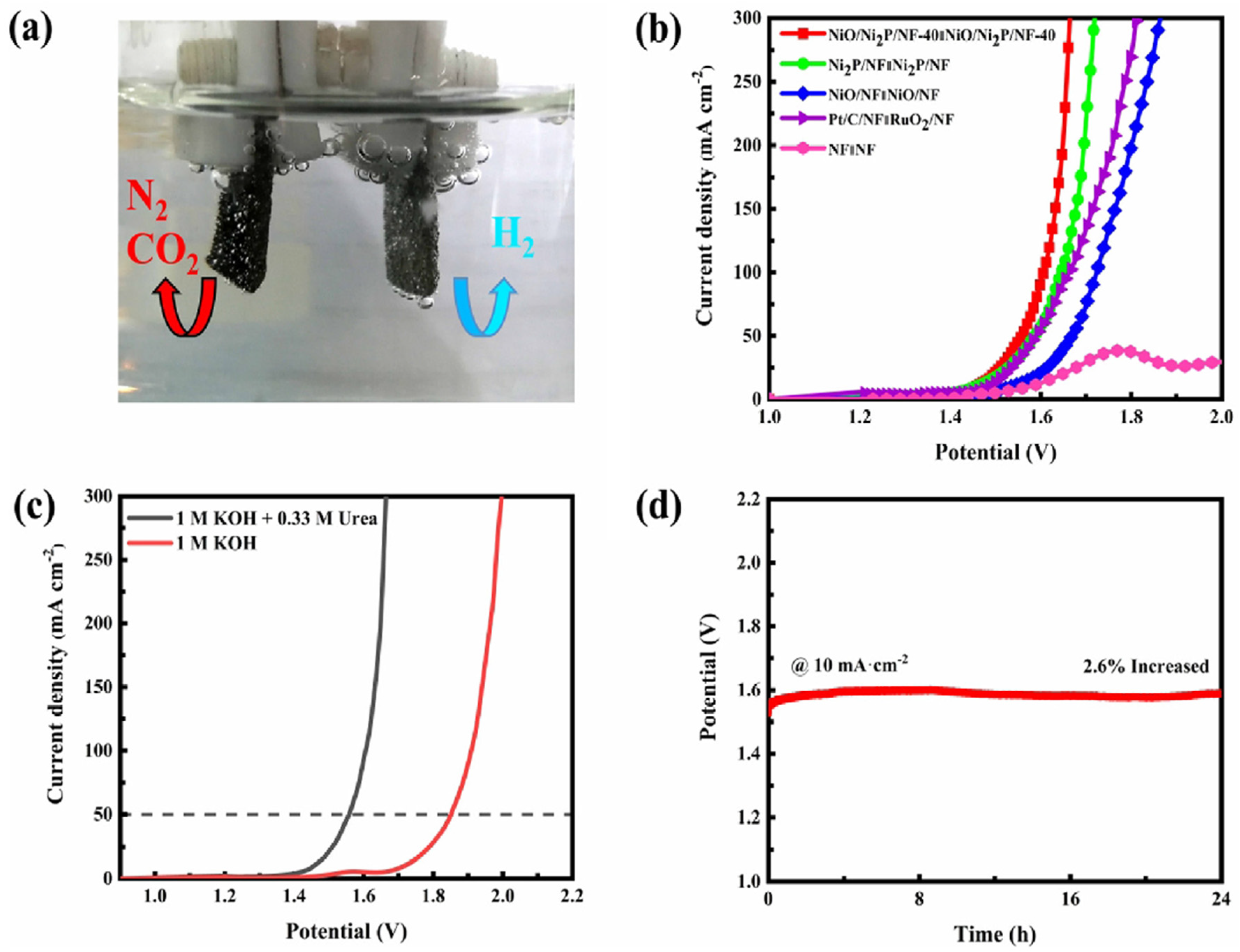
- Xu, X.; Ji, S.; Wang, H.; Wang, X.; Linkov, V.; Wang, R. Porous hetero-structured nickel oxide/nickel phosphide nanosheets as bifunctional electrocatalyst for hydrogen production via urea electrolysis. J. Colloid Interface Sci. 2022, 615, 163–172. [Google Scholar] [CrossRef]
- Wen, X. NiFe-LDH/MWCNTs/NF nanohybrids as a high-performance bifunctional electrocatalyst for overall urea electrolysis. Int. J. Hydrogen Energy 2020, 45, 14660–14668. [Google Scholar] [CrossRef]
- Babar, P.; Lokhande, A.; Karade, V.; Pawar, B.; Gang, M.G.; Pawar, S.; Kim, J.H. Bifunctional 2D electrocatalysts of transition metal hydroxide nanosheet arrays for water splitting and urea electrolysis. ACS Sustain. Chem. Eng. 2019, 7, 10035–10043. [Google Scholar] [CrossRef]
- Song, W.; Xu, M.; Teng, X.; Niu, Y.; Gong, S.; Liu, X.; He, X.; Chen, Z. Construction of self-supporting, hierarchically structured caterpillar-like NiCo2S4 arrays as an efficient trifunctional electrocatalyst for water and urea electrolysis. Nanoscale 2021, 13, 1680–1688. [Google Scholar] [CrossRef] [PubMed]
- Hao, P.; Zhu, W.; Li, L.; Tian, J.; Xie, J.; Lei, F.; Cui, G.; Zhang, Y.; Tang, B. Nickel incorporated Co9S8 nanosheet arrays on carbon cloth boosting overall urea electrolysis. Electrochim. Acta 2020, 338, 135883. [Google Scholar] [CrossRef]
- Wang, S.; Zhao, L.; Li, J.; Tian, X.; Wu, X.; Feng, L. High valence state of Ni and Mo synergism in NiS2-MoS2 hetero-nanorods catalyst with layered surface structure for urea electrocatalysis. J. Energy Chem. 2022, 66, 483–492. [Google Scholar] [CrossRef]
- Liu, M.; Jiao, Y.; Zhan, S.; Wang, H. Ni3S2 nanowires supported on Ni foam as efficient bifunctional electrocatalyst for urea-assisted electrolytic hydrogen production. Catal. Today 2020, 355, 596–601. [Google Scholar] [CrossRef]
- He, M.; Feng, C.; Liao, T.; Hu, S.; Wu, H.; Sun, Z. Low-cost Ni2P/Ni0.96S heterostructured bifunctional electrocatalyst toward highly efficient overall urea-water electrolysis. ACS Appl. Mater. Interface 2019, 12, 2225–2233. [Google Scholar] [CrossRef]
- Wang, X.; Wang, J.; Sun, X.; Wei, S.; Cui, L.; Yang, W.; Liu, J. Hierarchical coral-like NiMoS nanohybrids as highly efficient bifunctional electrocatalysts for overall urea electrolysis. Nano Res. 2018, 11, 988–996. [Google Scholar] [CrossRef]
- Maleki, M.; Darband, G.B.; Rouhaghdam, A.S.; Andaveh, R.; Kazemi, Z.M. Mn-incorporated nickel selenide: An ultra-active bifunctional electrocatalyst for hydrogen evolution and urea oxidation reactions. Chem. Commun. 2022, 58, 3545–3548. [Google Scholar] [CrossRef]
- Wang, H.; Jiao, X.; Zeng, W.; Zhang, Y.; Jiao, Y. Electrodeposition NiMoSe ternary nanoshperes on nickel foam as bifunctional electrocatalyst for urea electrolysis and hydrogen evolution reaction. Int. J. Hydrogen Energy 2021, 46, 37792–37801. [Google Scholar] [CrossRef]
- Chen, N.; Du, Y.-X.; Zhang, G.; Lu, W.-T.; Cao, F.-F. Amorphous Nickel Sulfoselenide for Efficient Electrochemical Urea-Assisted Hydrogen Production in Alkaline Media. Nano Energy 2021, 81, 105605. [Google Scholar] [CrossRef]
- Xu, X.; Du, P.; Guo, T.; Zhao, B.; Wang, H.; Huang, M. In situ grown Ni phosphate@ Ni12P5 nanorod arrays as a unique core–shell architecture: Competitive bifunctional electrocatalysts for urea electrolysis at large current densities. ACS Sustain. Chem. Eng. 2020, 8, 7463–7471. [Google Scholar] [CrossRef]
- Sha, L.; Yin, J.; Ye, K.; Wang, G.; Zhu, K.; Cheng, K.; Yan, J.; Wang, G.; Cao, D. The construction of self-supported thorny leaf-like nickel-cobalt bimetal phosphides as efficient bifunctional electrocatalysts for urea electrolysis. J. Mater. Chem. A 2019, 7, 9078–9085. [Google Scholar] [CrossRef]
- Yun, W.H.; Das, G.; Kim, B.; Park, B.J.; Yoon, H.H.; Yoon, Y.S. Ni-Fe phosphide deposited carbon felt as free-standing bifunctional catalyst electrode for urea electrolysis. Sci. Rep. 2021, 11, 22003. [Google Scholar] [CrossRef]
- Yan, L.; Sun, Y.; Hu, E.; Ning, J.; Zhong, Y.; Zhang, Z.; Hu, Y. Facile In-Situ Growth of Ni2P/Fe2P Nanohybrids on Ni Foam for Highly Efficient Urea Electrolysis. J. Colloid Interface Sci. 2019, 541, 279–286. [Google Scholar] [CrossRef]
- Yan, L.; Jiang, H.; Xing, Y.; Wang, Y.; Liu, D.; Gu, X.; Dai, P.; Li, L.; Zhao, X. Nickel metal–organic framework implanted on graphene and incubated to be ultrasmall nickel phosphide nanocrystals acts as a highly efficient water splitting electrocatalyst. J. Mater. Chem. A 2018, 6, 1682–1691. [Google Scholar] [CrossRef]
- Zhang, L.; Yan, Z.; Chen, X.; Yu, M.; Liu, F.; Cheng, F.; Chen, J. Facile synthesis of amorphous MoSx-Fe anchored on Zr-MOFs towards efficient and stable electrocatalytic hydrogen evolution. Chem. Commun. 2020, 56, 2763–2766. [Google Scholar] [CrossRef]
- Wang, H.; Zou, H.; Liu, Y.; Liu, Z.; Sun, W.; Lin, K.A.; Li, T.; Luo, S. Ni2P nanocrystals embedded Ni-MOF nanosheets supported on nickel foam as bifunctional electrocatalyst for urea electrolysis. Sci. Rep. 2021, 11, 21414. [Google Scholar] [CrossRef]
- Wang, L.; Ren, L.; Wang, X.; Feng, X.; Zhou, J.; Wang, B. Multivariate MOF-templated pomegranate-like Ni/C as efficient bifunctional electrocatalyst for hydrogen evolution and urea oxidation. ACS Appl. Mater. Interface 2018, 10, 4750–4756. [Google Scholar] [CrossRef]
- Xu, H.; Ye, K.; Zhu, K.; Yin, J.; Yan, J.; Wang, G.; Cao, D. Efficient bifunctional catalysts synthesized from three-dimensional Ni/Fe bimetallic organic frameworks for overall urea electrolysis. Dalton Trans. 2020, 49, 5646–5652. [Google Scholar] [CrossRef]
- Wang, F.; Zhao, D.; Zhang, L.; Fan, L.; Zhang, X.; Hu, S. Nanostructured nickel nitride with reduced graphene oxide composite bifunctional electrocatalysts for an efficient water-urea splitting. Nanomaterials 2019, 9, 1583. [Google Scholar] [CrossRef] [PubMed]
- Zhao, Z.; Zhao, J.; Wang, H.; Li, X.; Yang, L.; Zhao, Z.; Liu, X.; Liu, Y.; Liu, P.; Cai, Z. Porous flower-like nickel nitride as highly efficient bifunctional electrocatalysts for less energy-intensive hydrogen evolution and urea oxidation. Int. J. Hydrogen Energy 2020, 45, 14199–14207. [Google Scholar] [CrossRef]
- Li, R.Q.; Liu, Q.; Zhou, Y.; Lu, M.; Hou, J.; Qu, K.; Zhu, Y.; Fontaine, O. 3D self-supported porous vanadium-doped nickel nitride nanosheet arrays as efficient bifunctional electrocatalysts for urea electrolysis. J. Mater. Chem. A 2021, 9, 4159–4166. [Google Scholar] [CrossRef]
- Hu, S.; Wang, S.; Feng, C.; Wu, H.; Zhang, J.; Mei, H. Novel MOF-derived nickel nitride as high-performance bifunctional electrocatalysts for hydrogen evolution and urea oxidation. ACS Sustain. Chem. Eng. 2020, 8, 7414–7422. [Google Scholar] [CrossRef]
- Zhang, Y.; Qiu, Y.; Wang, Y.; Li, B.; Zhang, Y.; Ma, Z.; Liu, S. Coaxial Ni-S@N-Doped Carbon Nanofibers Derived Hierarchical Electrodes for Efficient H2 Production via Urea Electrolysis. ACS Appl. Mater. Interface 2021, 13, 3937–3948. [Google Scholar] [CrossRef]
- Ligani Fereja, S.; Li, P.; Zhang, Z.; Guo, J.; Fang, Z.; Li, Z.; He, S.; Chen, W. W-Doping Induced Abundant Active Sites in a 3D NiS2/MoO2 Heterostructure as an Efficient Electrocatalyst for Urea Oxidation and Hydrogen Evolution Reaction. Chem. Eng. J. 2022, 432, 134274. [Google Scholar] [CrossRef]
- Fang, K.L.; Wu, T.H.; Hou, B.W.; Lin, H.R. Green Synthesis of Ni3S2 Nanoparticles from a Nontoxic Sulfur Source for Urea Electrolysis with High Catalytic Activity. Electrochim. Acta 2022, 421, 140511. [Google Scholar] [CrossRef]
- Wu, T.H.; Zhan, J.J.; Hou, B.W.; Qiu, Z.T. One-step synthesis of NiS2/rGO composite for efficient electrocatalytic urea oxidation. MRS Energy Sustain. 2022; in press. [Google Scholar] [CrossRef]
- Liu, H.; Liu, Z.; Feng, L. Bonding State Synergy of the NiF2/Ni2P Hybrid with the Co-Existence of Covalent and Ionic Bonds and the Application of This Hybrid as a Robust Catalyst for the Energy-Relevant Electrooxidation of Water and Urea. Nanoscale 2019, 11, 16017–16025. [Google Scholar] [CrossRef]
- Yang, J.-H.; Song, X.; Zhao, X.; Wang, Y.; Yang, Y.; Gao, L. Nickel Phosphate Materials Regulated by Doping Cobalt for Urea and Methanol Electro-Oxidation. Int. J. Hydrogen Energy 2019, 44, 16305–16314. [Google Scholar] [CrossRef]
- Forslund, R.P.; Mefford, J.T.; Hardin, W.G.; Alexander, C.T.; Johnston, K.P.; Stevenson, K.J. Nanostructured LaNiO3 Perovskite Electrocatalyst for Enhanced Urea Oxidation. ACS Catal. 2016, 6, 5044–5051. [Google Scholar] [CrossRef]


| Catalysts | Onset Potential (V vs. RHE) at 10 mA/cm2 | Current Density at 1.5 (V vs. RHE) | Electrolyte | Reference |
|---|---|---|---|---|
| Ni(OH)2 nanomeshes | 1.35 | ~22 mA cm−2 | 1 M KOH + 0.33 M urea | [28] |
| Ni(OH)2 nanoflakes | ~1.43 | ~50 mA cm−2 | 1 M KOH + 0.33 M urea | [30] |
| C@NiO | ~1.32 | ~75 mA cm–2 | 1 M KOH + 0.33 M urea | [32] |
| Vertically aligned NiO nanosheets/NF | ~1.38 | ~75 mA cm–2 | 1 M KOH + 0.33 M urea | [35] |
| NiS@Ni3S2/NiMoO4 | ~1.31 | ~148 mA cm–2 | 1 M KOH + 0.5 M urea | [42] |
| Ni3S2-Ni3P | ~1.35 | ~150 mA cm–2 | 1 M KOH + 0.5 M urea | [43] |
| NiCo LDH-NO3 | 1.30 | ~58 mA cm–2 | 1 M KOH + 0.33 M urea | [46] |
| α−Ni(OH)2 | 1.40 | 58 mA cm–2 | 1 M KOH + 0.33 M urea | [47] |
| α−Ni(OH)2 with Ni vacancies | ~1.41 | ~52 mA cm–2 | 1 M KOH + 0.33 M urea | [48] |
| NiCr hydroxide | ~1.41 | ~42 mA cm–2 | 1 M KOH + 0.33 M urea | [51] |
| NiS2/SnS2 | 1.36 | ~75 mA cm–2 | 1 M KOH + 0.33 M urea | [57] |
| S-Ni(OH)2 | 1.32 | ~35 mA cm−2 | 1 M KOH + 0.33 M urea | [58] |
| Fe-Ni3S2 | ~1.37 | ~200 mA cm–2 | 1 M KOH + 0.33 M urea | [59] |
| Ni@N-doped CNT | ~1.39 | ~36 mA cm−2 | 1 M KOH + 0.5 M urea | [64] |
| Catalyst Material | Current Density | Overpotential for HER | Electrolyte | Reference |
|---|---|---|---|---|
| NiMo nanowire arrays | 10 mA cm−2 | 17 mV | 0.5 M H2SO4 | [66] |
| Ni3N nanosheets | 100 mA cm−2 | 100 mV | 0.5 M H2SO4 | [67] |
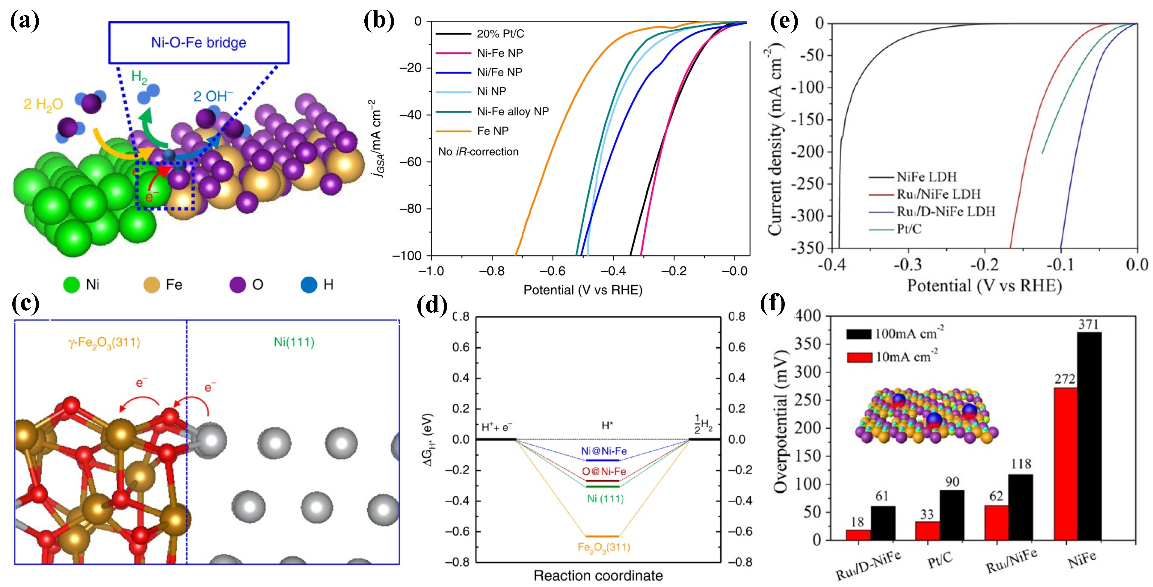
| Ni-Fe NP | 10 mA cm−2 | 100 mV | 1.0 M KOH | [69] |
| Ru1/D-NiFe LDH | 10 mA cm−2 | 18 mV | 1.0 M KOH | [70] |
| Ni-GF/VC | 10 mA cm−2 | 128 mV | 1.0 M KOH | [71] |
| h-NiS | 10 mA cm−2 | 136 mV | 1.0 M KOH | [73] |
| Ni-P–Pt/NF | 10 mA cm−2 | 34 mV | 1.0 M KOH | [74] |
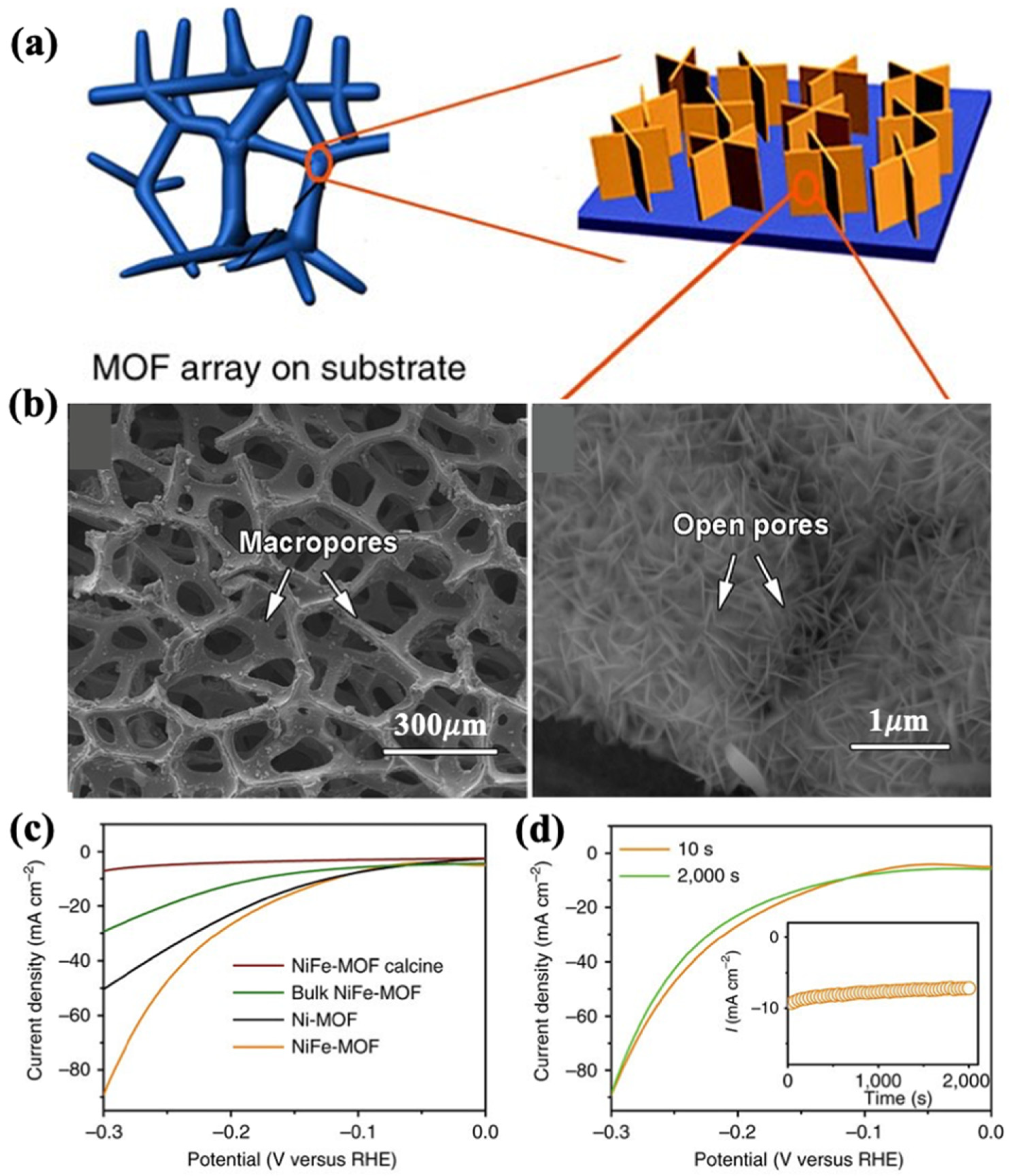
| FeNi-MOF | 10 mA cm−2 | 134 mV | 0.1 M KOH | [79] |
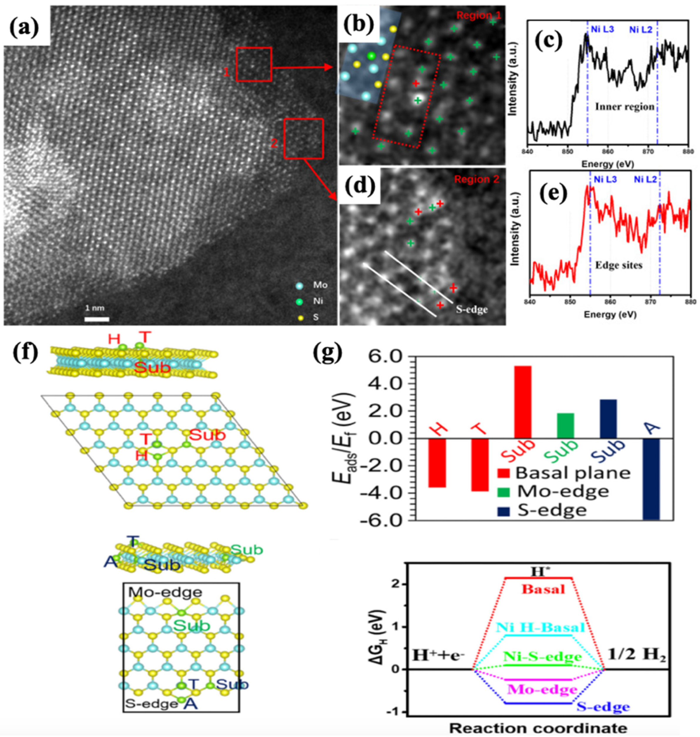
| NiSA-MoS2/CC | 10 mA cm−2 | 98 mV | 1.0 M KOH | [81] |
| 10 mA cm−2 | 110mV | 0.5 M H2SO4 | [81] | |
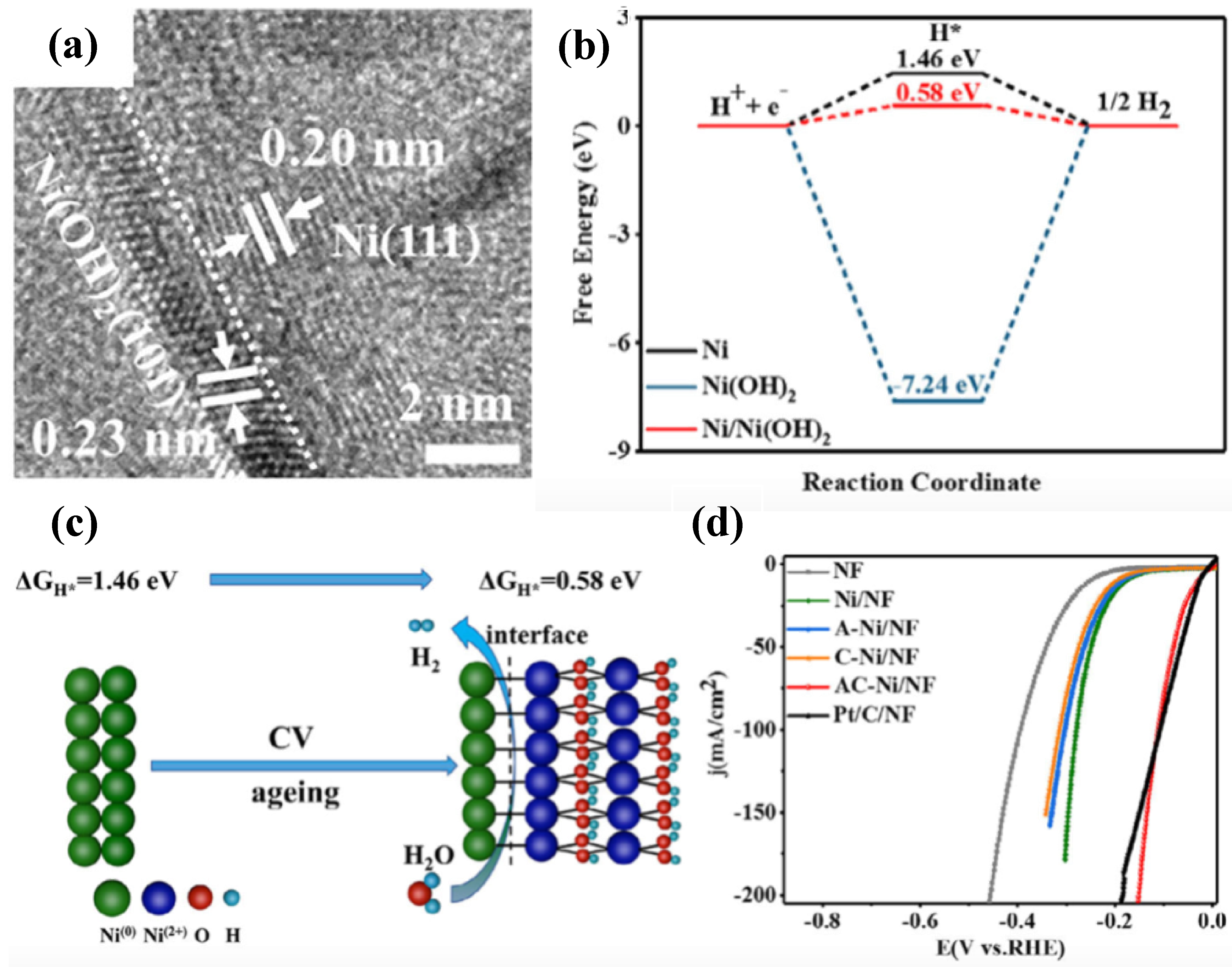
| AC–Ni/NF | 10 mA cm−2 | 30 mV | 1.0 M KOH | [82] |
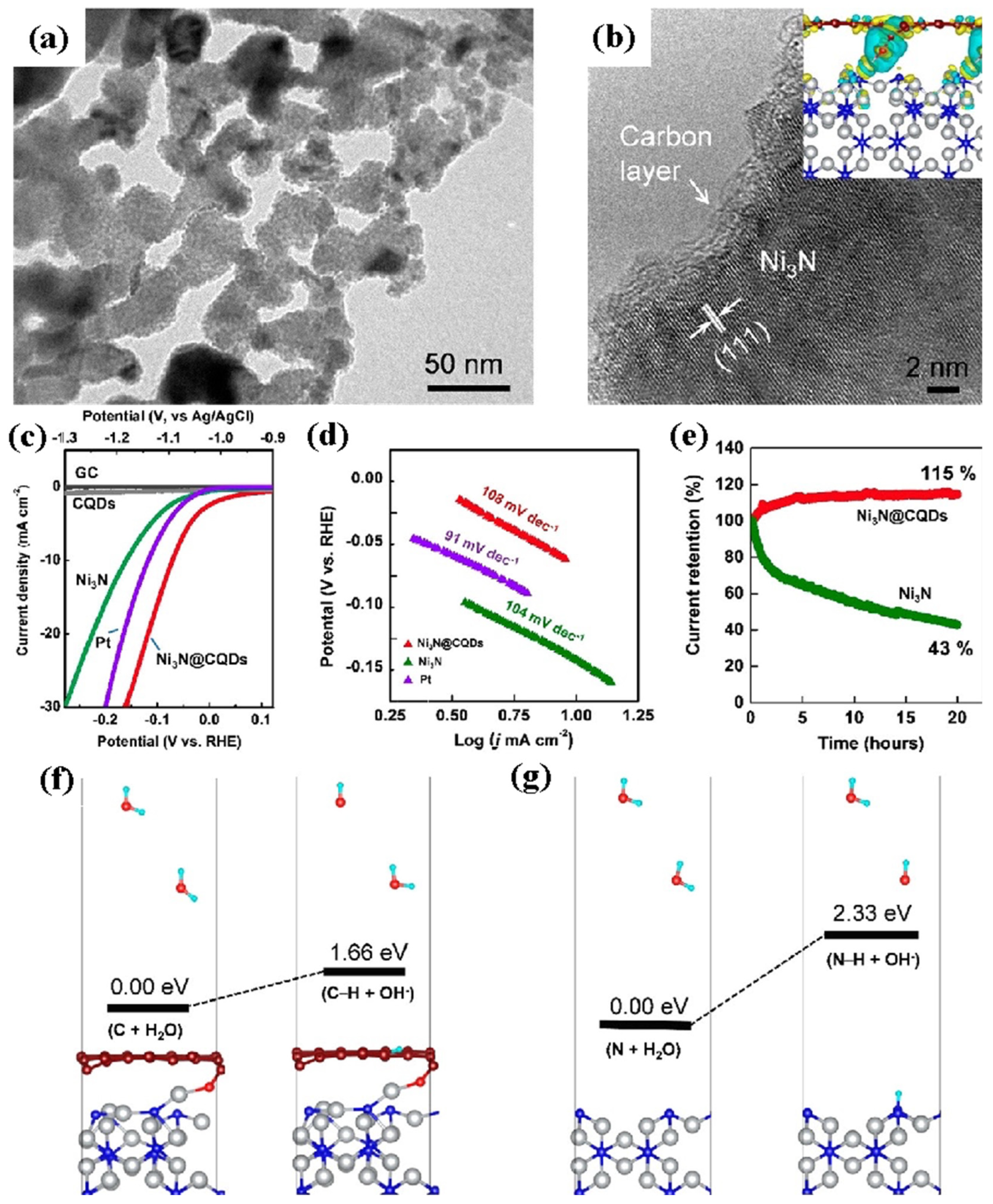
| Ni3N@CQDs | 10 mA cm−2 | 69 mV | 1.0 M KOH | [83] |
| Catalyst Material | Onset Potential or UOR | Current Density | Overpotential for HER | Current Density | Potential Required for Urea Electrolyzer | Reference |
|---|---|---|---|---|---|---|
| NiO/Ni2P | 1.338 V | 10 mA cm−2 | 137 mV dec−1 | 10 mA cm−2 | 1.457 V at 10 mA cm−2 | [90] |
| NiFe-LDH/MWCNTs/NF | 1.335 V | 10 mA cm−2 | 98 mV dec−1 | 10 mA cm−2 | 1.507 V at 10 mA cm−2 | [91] |
| NiFeCo LDH/NF | 0.280 V (vs. SCE) | 10 mA cm−2 | 108 mV dec−1 | 10 mA cm−2 | 1.49 V at 10 mA cm−2 | [92] |
| (Ni3S2@NF) | 0.36 V (vs. SCE) | 100 mA cm−2 | 127 mV dec−1 | 10 mA cm−2 | 1.49 V at 20 mA cm−2 | [96] |
| Ni2P/Ni0.96S | 1.442 V | 100 mA cm−2 | 239 mV dec−1 | 100 mA cm−2 | 1.453 V at 100 mA cm−2 | [98] |
| HC-NiMoS/Ti) | 1.38 V | 60 mA cm−2 | 93.1 mV dec−1 | 10 mA cm−2 | 1.59 V at 10 mA cm−2 | [99] |
| NiMoSe/NF) | 1.39 V | 10 mA cm−2 | 89 mV dec−1 | 10 mA cm−2 | 1.44 V at 10 mA cm−2 | [101] |
| Ni-S-Se/NF | 1.38 V | 10 mA cm−2 | 98 mV dec−1 | 10 mA cm−2 | 1.47 V at 10 mA cm−2 | [102] |
| Ni12P5/Ni-P/NF | 1.337 V | 100 mA cm−2 | 98.6 mV dec−1 | 10 mA cm−2 | 1.662 V at 500 mA cm−2 | [103] |
| (NiCoP/CC) | 1.30 V | 10 mA cm−2 | 107 mV dec−1 | 10 mA cm−2 | 1.42 V at 10 mA cm−2 | [104] |
| P-NiFe@CF | 1.39 V | 200 mA cm−2 | 23 mV dec−1 | 10 mA cm−2 | 1.37 V at 10 mA cm−2 | [105] |
| Ni2P/Fe2P/NF) | 1.36 V | 10 mA cm−2 | 115 mV dec−1 | 10 mA cm−2 | 1.47 V at 10 mA cm−2 | [106] |
| Ni/C | 1.33 V | 10 mA cm−2 | 40 mV dec−1 | 10 mA cm−2 | 1.6 V at 10 mA cm−2 | [109] |
| MOF-Ni@MOF-Fe-S | 1.347 V | 10 mA cm−2 | 96 mV dec−1 | 10 mA cm−2 | 1.539 V at 10 mA cm−2 | [110] |
| V–Ni3N/NF | 1.361 V | 10 mA cm−2 | −83 mV dec−1 | 10 mA cm−2 | 1.416 V at 10 mA cm−2 | [113] |
| Ni3N-350/NF | 1.34 V | 10 mA cm−2 | 128 mV dec−1 | 10 mA cm−2 | 1.51 V at 100 mA cm−2 | [112] |
Publisher’s Note: MDPI stays neutral with regard to jurisdictional claims in published maps and institutional affiliations. |
© 2022 by the authors. Licensee MDPI, Basel, Switzerland. This article is an open access article distributed under the terms and conditions of the Creative Commons Attribution (CC BY) license (https://creativecommons.org/licenses/by/4.0/).
Share and Cite
Anuratha, K.S.; Rinawati, M.; Wu, T.-H.; Yeh, M.-H.; Lin, J.-Y. Recent Development of Nickel-Based Electrocatalysts for Urea Electrolysis in Alkaline Solution. Nanomaterials 2022, 12, 2970. https://doi.org/10.3390/nano12172970
Anuratha KS, Rinawati M, Wu T-H, Yeh M-H, Lin J-Y. Recent Development of Nickel-Based Electrocatalysts for Urea Electrolysis in Alkaline Solution. Nanomaterials. 2022; 12(17):2970. https://doi.org/10.3390/nano12172970
Chicago/Turabian StyleAnuratha, Krishnan Shanmugam, Mia Rinawati, Tzu-Ho Wu, Min-Hsin Yeh, and Jeng-Yu Lin. 2022. "Recent Development of Nickel-Based Electrocatalysts for Urea Electrolysis in Alkaline Solution" Nanomaterials 12, no. 17: 2970. https://doi.org/10.3390/nano12172970
APA StyleAnuratha, K. S., Rinawati, M., Wu, T.-H., Yeh, M.-H., & Lin, J.-Y. (2022). Recent Development of Nickel-Based Electrocatalysts for Urea Electrolysis in Alkaline Solution. Nanomaterials, 12(17), 2970. https://doi.org/10.3390/nano12172970