Article

Non-Stacked γ-Fe2O3/C@TiO2 Double-Layer Hollow Nanoparticles for Enhanced Photocatalytic Applications under Visible Light

1
Yantai Key Laboratory of Gold Catalysis and Engineering, Shandong Applied Research Center of Gold Nanotechnology (Au-SDARC), School of Chemistry & Chemical Engineering, Yantai University, Yantai 264005, China
2
Biomedical Research Center, Northwest Minzu University, Lanzhou 730000, China
3
School of Environmental Science and Engineering, Hebei University of Science and Technology, Shijiazhuang 050018, China
*
Authors to whom correspondence should be addressed.
Nanomaterials 2022, 12(2), 201; https://doi.org/10.3390/nano12020201
Submission received: 25 November 2021 / Revised: 23 December 2021 / Accepted: 27 December 2021 / Published: 7 January 2022

Abstract

:
Herein, a non-stacked γ-Fe2O3/C@TiO2 double-layer hollow nano photocatalyst has been developed with ultrathin nanosheets-assembled double shells for photodegradation phenol. High catalytic performance was found that the phenol could be completely degraded in 135 min under visible light, due to the moderate band edge position (VB at 0.59 eV and CB at −0.66 eV) of the non-stacked γ-Fe2O3/C@TiO2, which can expand the excitation wavelength range into the visible light region and produce a high concentration of free radicals (such as ·OH, ·O2−, holes). Furthermore, the interior of the hollow composite γ-Fe2O3 is responsible for charge generation, and the carbon matrix facilitates charge transfer to the external TiO2 shell. This overlap improved the selection/utilization efficiency, while the unique non-stacked double-layered structure inhibited initial charge recombination over the photocatalysts. This work provides new approaches for photocatalytic applications with γ-Fe2O3/C-based materials.

Graphical Abstract

1. Introduction

Phenol containing wastewater is produced in many industries, such as pharmaceuticals, polymer, dye, etc. [1]. Once phenol is released into the environment, it cannot be degraded inherently under the natural environment, and it causes harm to human health [2,3]. The phenol degradation is complex due to the high conjugated molecular system [4] and lower phenol concentration is also toxic [2]. Therefore, designing an environmentally friendly, cost-effective and highly efficient approach for phenol treatment is urgent. Photocatalysis is a simple technology among water treatment technologies [5,6,7], owing to its high mineralization and sturdy treatment efficiency [8,9].
Titanium dioxide (TiO2) is the most-used semiconductor material in the photocatalytic field, due to its chemical/physical excellent profound mineralization capability and stability under ultraviolet light [10]. However, two significant problems need to be solved: The low specific surface area of TiO2 (50 m2/g for P25, TiO2 with a mixed rutile phase, and anatase phase with an average particle size of 25 nm) confines its adsorption capacity for pollutant molecules. Additionally, it has a wide energy gap and is challenging to utilize visible light. Therefore, the preparation of a TiO2 catalyst with an extensive specific surface area and response to visible light is the bottleneck problem in applying TiO2.
To enhance the visible light absorption capacity, the commonly used means [11] are constructing heterojunction, defect engineering, and element doping. The construction of heterojunction catalysts can enhance the absorption of visible light and enhance the separation efficiency of photogenerated carriers because photogenerated electrons and holes can migrate from one phase to another through the two-phase interface, which can effectively inhibit the recombination of the photogenerated carriers [12,13,14]. More recently, double-layer hollow microsphere semiconductor catalysts have been applied as photocatalysts [15]. By virtue of the advantages of the double-layer structure, the heterogeneous junction catalyst based on the double layer structure is explored.
The construction of a core-shell heterojunction, γ-Fe2O3, maybe an ideal inner material that can improve solar energy utilization efficiency, which can also simplify the separation process with magnetic properties [16]. Most of the related work has concentrated on the design of functional cores or shells, but the effect of space accumulation between the two layers has been neglected. Based on the photocatalysis mechanism [17,18,19], the specific energy barrier formed at the interface between the core and the shell can be changed by adjusting the overlap mode between the two layers, promoting the separation of photogenerated carriers. Hence, the structure of the outer TiO2 needs a directional design. It is an urgent problem to build a non-simple stacked TiO2 shell and increase its specific surface area.
Recently, Zhao’s group [20] developed a TiO2 shell material composed of ultrathin nanosheets. This shell material composed of ultrathin TiO2 nanosheets increases the specific surface area of the catalyst. It constructs a non-simple stacked core-shell structure, making the catalyst appear in a porous state, which improves the light utilization rate and the adsorption capacity of pollutant molecules. Because the structure permits light scattering and refraction, the diffusion distance of photogenerated electron-hole pairs is reduced, and the light utilization is maximized [4].
This study demonstrates a facile route to synthesize non-stacked γ-Fe2O3/C@TiO2 double-layer hollow nanoparticles. The C moiety constructs a channel for photo-generated electrons between iron oxide andTiO2, facilitating the electron transfer from the γ-Fe2O3 moiety to TiO2 moiety. The double-layer structure formed by stacking nanosheets has large pores, which alleviates the transmission of reactants in the catalyst. These constructs also inhibit the separation of electron-hole pairs and achieve a high treatment effect. In this study, phenol was selected as an indicator to study the catalyst’s efficiency for photocatalytic oxidation. We found that two-step charge generation and charge transfer were matched and synergistically enhanced in the non-stacked γ-Fe2O3/C@TiO2 double-layer hollow nanoparticles, which significantly improved the photodegradation of phenol.

2. Materials and Methods

2.1. Catalyst Preparation

2.1.1. Materials

Ferrocene, hydrogen peroxide (H2O2), acetone, phenol, BaSO4 and ethanol anhydrous were guarantee-grade reagents from Beijing Chemicals Co. Ltd. (Beijing, China). Concentrated ammonia solution (28 wt%), ethylene glycol, sodium acetate, tetra-butyl titanate (TBOT), tetraethyl orthosilicate (TEOS), HCl, NaOH and trisodium citrate were purchased from Tianjin Chemical Corp (Tianjin, China) and were analytical grade. All the water used for all experiments was deionized.

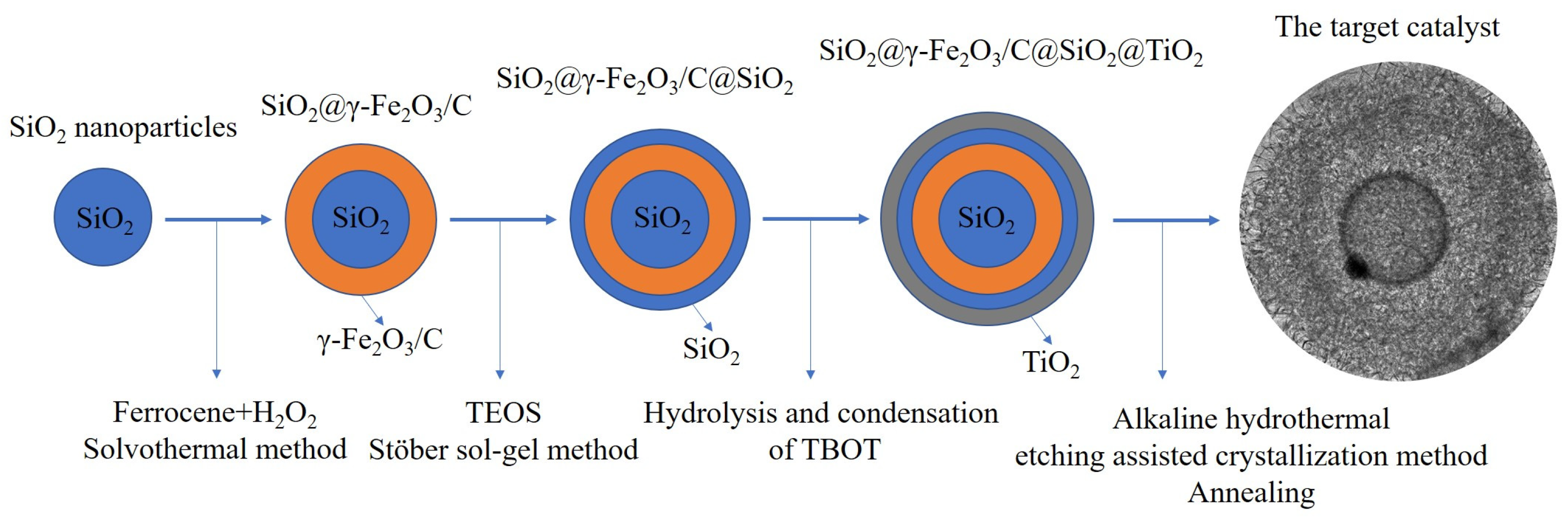
2.1.2. Synthesis of Non-Stacked γ-Fe2O3/C@TiO2 Double-Layer Hollow Nanoparticles

Figure 1 shows the synthesis approaches for the non-stacked γ-Fe2O3/C@TiO2 double-layer hollow nanoparticles. In this fraction, the nanoparticles were prepared by the following steps.
(1)
Synthesis of SiO2@γ-Fe2O3/C nanoparticles
Monodispersed SiO2 nanoparticles were first synthesized through the Stöber method. A modified hydrothermal approach prepared the core-shell SiO2/γ-Fe2O3/C nanoparticles. Silica nanoparticles (100 mg) and ferrocene (200 mg) were suspended in ethanol (65 mL) using ultrasonic for 30 min. Then, 2 mL H2O2 was dropwise counted into the mixture and cruised with energetic stirring for 1.5 h. A Teflon-lined stainless-steel autoclave(TEFIC BIOTECH CO., Xi'an, China) was used to heat the homogeneous solution at 210 °C for 48 h. The product was obtained after the autoclave cooled down to room temperature (3 h). Acetone and ethanol were used to wash the obtained products 3 times, respectively, and then the product was vacuum-dried for 12 h.
(2)
Synthesis of SiO2@γ-Fe2O3/C@SiO2 nanoparticles
The Fe2O3/C@SiO2 nanoparticles (0.3 g) obtained from the last step were added into a three-neck round-bottom flask filled with the ammonia solution (5.0 mL, 28 wt%), ethanol anhydrous (280 mL), and deionized water (70 mL), ultrasonicate for 20 min. TEOS (4 mL) was added dropwise to the mixture in 10 min. The reaction mixture was mechanically stirred for 10 h at room temperature before the products separated. Then the final product was then washed 3 times, respectively, using ethanol and deionized water, and dried in vacuum.
(3)
Synthesis of SiO2@γ-Fe2O3/C@SiO2@TiO2 nanoparticles
The core-shell SiO2@γ-Fe2O3/C@SiO2@TiO2 nanoparticles were synthesized using the condensation and hydrolysis of TBOT. Ethanol anhydrous (200 mL) was used to disperse the obtained SiO2@γ-Fe2O3/C@SiO2 nanoparticles (0.15 g) from the above procedure. Ammonia solution (0.9 mL, 28 wt%) was counted to the mixture and ultrasonicated for 15 min. TBOT (2.0 mL) was then added dropwise to the mixture in 5 min, followed by continuous mechanical stirring for 24 h at 45 °C. The products were separated by centrifugation and washed 3 times, using ethanol and deionized water, and dried under vacuum.
(4)
Synthesis of non-stacked γ-Fe2O3/C@TiO2 double-layer hollow nanoparticles
An alkaline hydrothermal etching-assisted crystallization approach was used to synthesize the final products, the SiO2@γ-Fe2O3/C@SiO2@TiO2 nanoparticles. The SiO2@γ-Fe2O3/C@SiO2@TiO2 nanoparticles (0.4 g) obtained above were added into a Teflon-lined stainless-steel autoclave (50 mL) filled with a NaOH aqueous solution (25 mL, 2.0 M). The autoclave was sealed and heated to 100 °C for 4 h and cooled to room temperature in 3 h before the next step. The final SiO2@γ-Fe2O3/C@SiO2@TiO2 nanoparticles were submerged in a HCl aqueous solution (100 mL, 0.1 M) for 20 min followed by washing with deionized water until pH value was close to 7. The final nanoparticles were then dried at 60 °C for 5 h. Finally, the catalyst was annealed at 400 °C for 4 h in an oxygen-deficient environment.

2.2. Catalyst Characterization

X-ray powder diffraction (XRD) patterns with 2θ ranging from 10 to 80° (40 kV and 30 mA, D/MAX-2500, Rigaku, Japan), as well as transmission electron microscopy (TEM, JEM-2100 Felectron microscope operating at 200 kV, Tokyo, Japan) were used to obtain the crystal and morphological structure. The samples’ specific surface areas were characterized by the Brunauer–Emmett–Teller (BET) model. Quadrasorb SI analyzer was used to obtain the N2 adsorption-desorption isotherms at 77 K. The Barrett–Joyner–Halenda (BJH) model was used to analyze the pore size and volume. X-ray photoelectron spectroscopy (XPS) was performed using a 5300 ESCA equipment (PerkinElmer PHI Co.,Hopkinton, Massachusetts, USA) with an Al Kα X-ray source (250 W) to investigate the chemical compositions of samples. A UV–vis spectrophotometer (UV-2600, Shimadzu, Tokyo, Japan) with BaSO4 was used to acquire the UV–vis diffuse reflection spectra (UV–vis DRS).

2.3. Catalytic Activity Measurement

The photocatalytic activity was evaluated using a photochemical reactor (TG-10B, Beijing, China) under xenon lamp (300 W). In each experiment, 0.1 g catalyst was weighed in a quartz glass tube, and 30 mL phenol (20 mg L−1) was added into it. Before photocatalytic reaction, a dark reaction was carried out for 30 min to achieve the equilibrium of adsorption and desorption of phenol. The absorbency of phenol was determined by a UV-VIS spectrophotometer.
According to absorbance conversion of phenol, the formula of photocatalytic reaction removal rate was shown in (1).
D % = A 0 A t A 0 × 100 %
  • A0—the initial absorbance of phenol.
  • At—Absorption of phenol at t min.

3. Results and Discussion

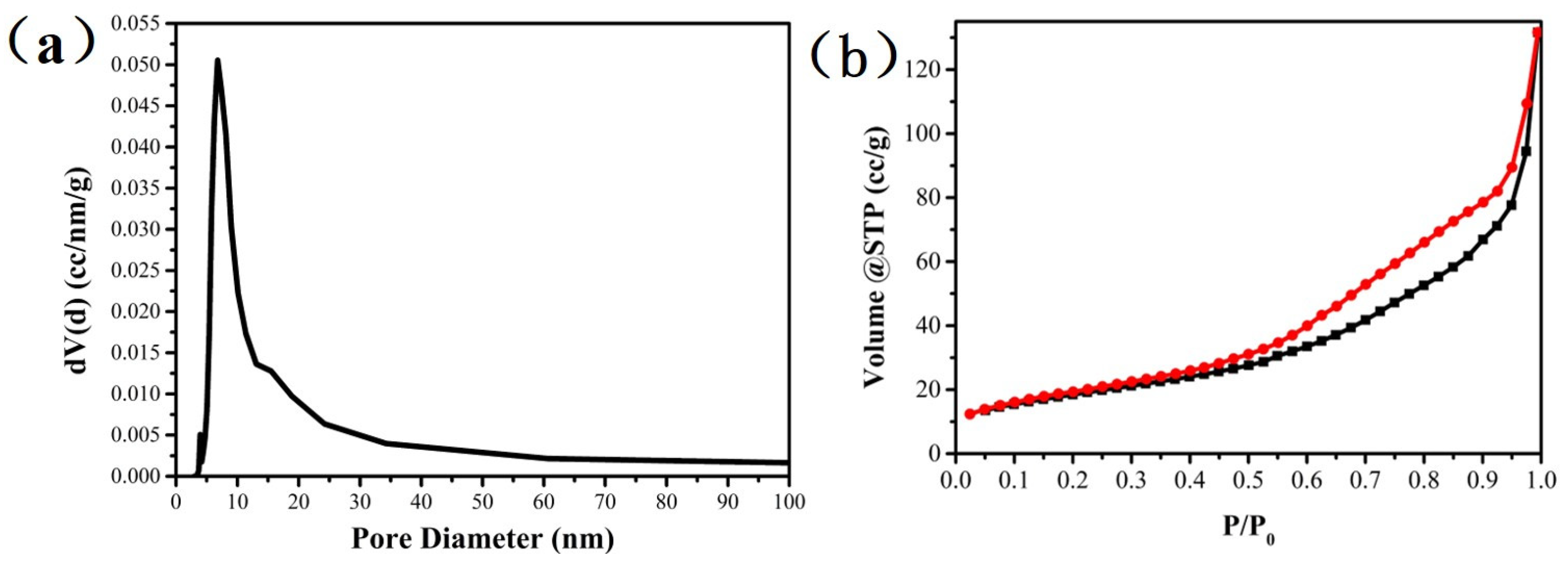
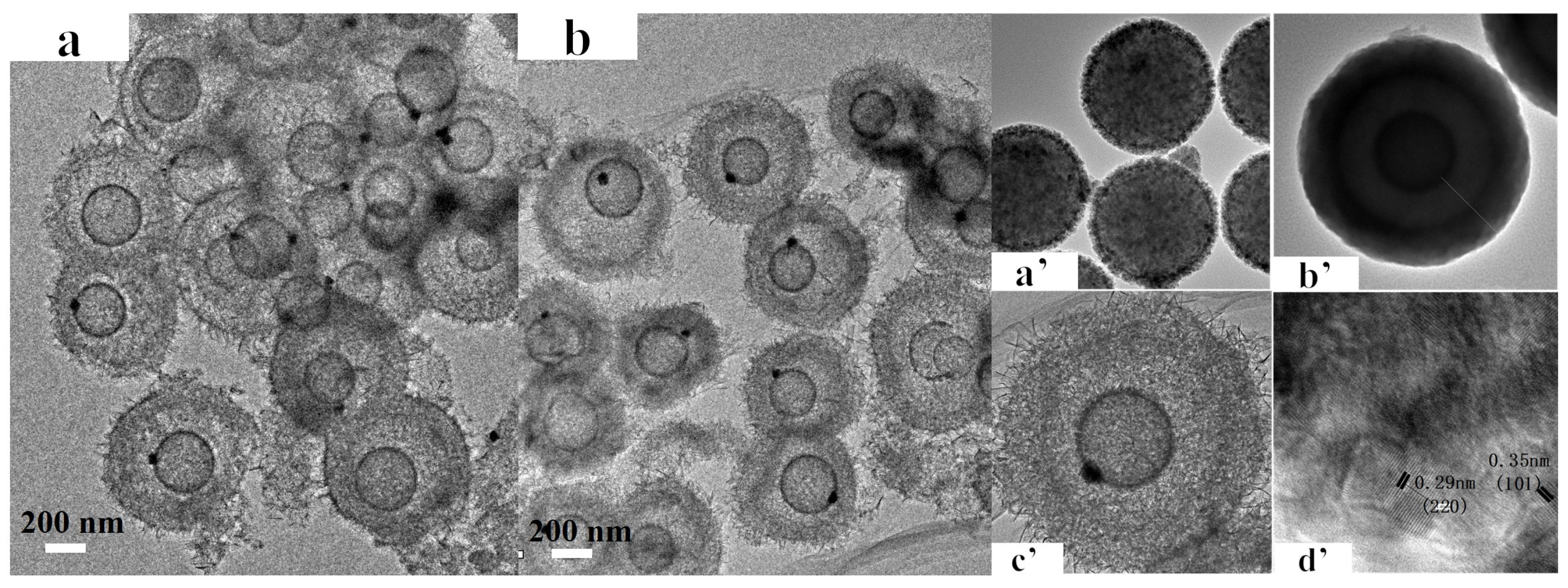
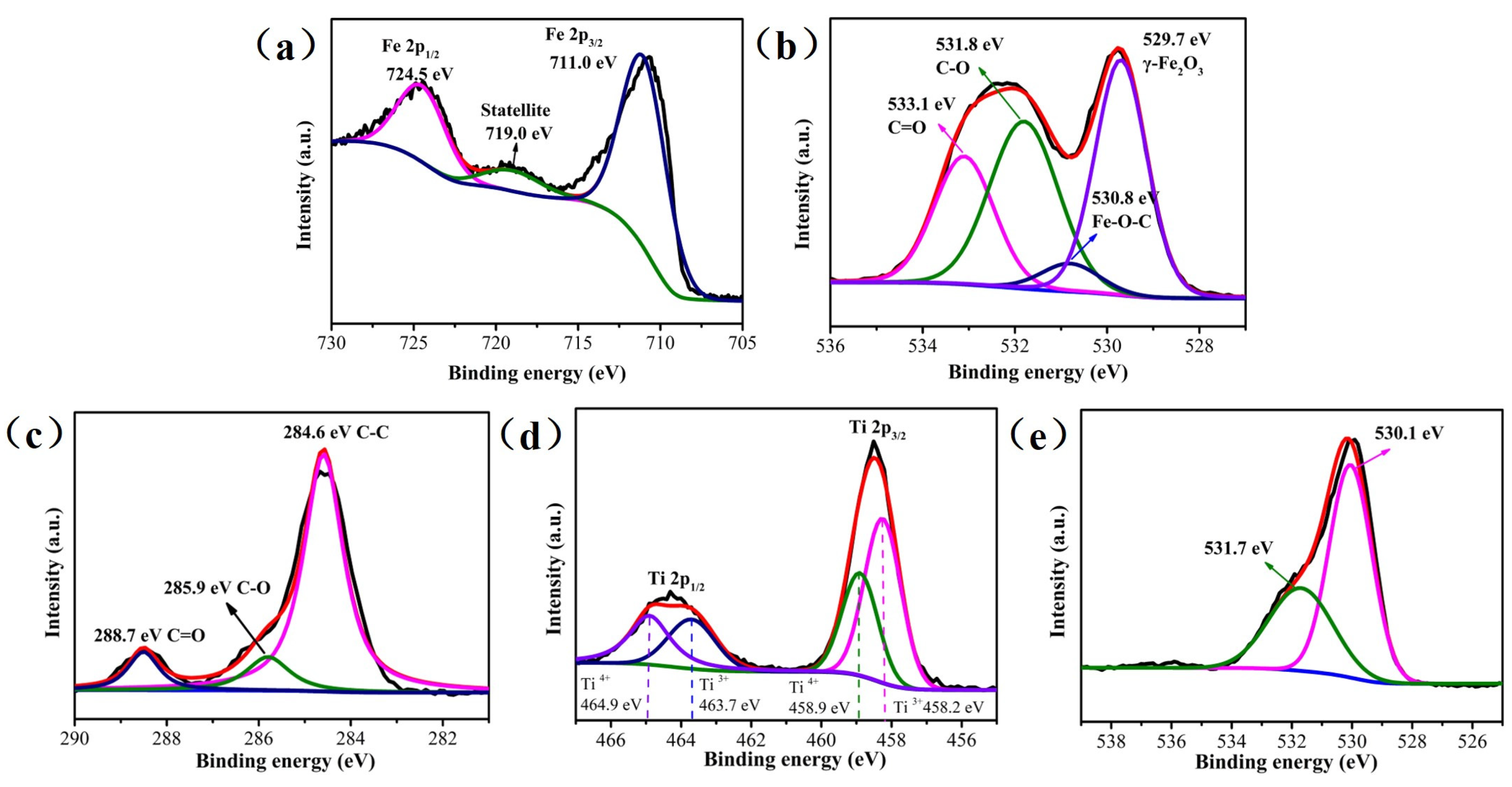
3.1. Textural Properties of Catalysts

The wide-angle XRD pattern of non-stacked γ-Fe2O3/C@TiO2 is shown in Figure 2a. The characteristic peaks of the catalyst were indexed to anatase TiO2 (JCPDS-ICDD21-1272) [21,22,23]. Other phases such as γ-Fe2O3 were not observed because the thick TiO2 shell passivated the X-ray diffraction. To better analyse the phase composition of the catalyst inner layer, the precursor (hollow γ-Fe2O3/C) of γ-Fe2O3/C@TiO2 was characterized by XRD also. As shown in Figure 2b, the diffraction peaks of γ-Fe2O3 (JCPDS-ICDD 25-1402) were observed in hollow γ-Fe2O3/C [24,25]. Figure 2c shows the Raman spectra of hollow γ-Fe2O3/C, stacked γ-Fe2O3/C@TiO2, and non-stacked γ-Fe2O3/C@TiO2. The five vibrational modes, located at 640, 545, 395, 193, and 142 cm−1, represent Eg Raman active, A1g + B1g, B1g, e.g., and Eg modes, indicating that the anatase is the dominant phase of the TiO2 hollow spheres.
The N2 adsorption-desorption was used to measure the specific surface area of the catalyst. Type IV isothermal curves and N2 hysteresis loops were observed in Figure 3a, which indicated that the non-stacked γ-Fe2O3/C@TiO2 was a mesoporous material. The pore volume and pore size distributions were also characterized. As shown in Figure 3b, the pore size was mainly distributed from 5–30 nm, which indicated the catalysts’ mesoporous nature. The hollow structure expected to endow the material with a larger specific surface area (145.328 m2/g), which has a strong ability to absorb pollution molecules so that the active species produced on its surface can directly react with pollutants and enhance the catalytic performance.
As shown in Figure 4a’, the γ-Fe2O3/C layer was firmly attached to the outer surface of the SiO2 sphere, and the wrapped SiO2@γ-Fe2O3/C nanoparticles exhibited relatively uniform spherical structures. Then, the thin layers of SiO2 and TiO2 were successfully coated on the surface of the SiO2@γ-Fe2O3/C core to form uniform SiO2@γ-Fe2O3/C@SiO2@TiO2 nanoparticles (Figure 4b’). After treatment in a hot alkaline solution, the silicon component was removed, and the TiO2 expanded both inside and outside to form non-stacked γ-Fe2O3/C@TiO2(Figure 4c’). ICP-AES results showed the nominal ratio of the components (Fe:Ti) was 3.9:1. Furthermore, from Figure 4a,b, almost all catalyst particles can maintain this particular structure. A clear lattice plane was exposed with interplanar spacings of 0.29 nm and 0.35 nm, which revealed the presence of anatase TiO2 and γ-Fe2O3/C, respectively, which mainly expressed the (220) and (101) lattice planes (Figure 4d’).
To further investigate the composition distribution of the inner shell, the Fe, C, and O species located in hollow γ-Fe2O3/C were characterized by XPS. The typical peaks of Fe2p3/2 and Fe2p1/2 were located at 711.0 and 724.5 eV, respectively (Figure 5a) [26,27,28]. The presence of the characteristic satellite peak at 719.0 eV confirmed the formation of γ-Fe2O3, which is the key characteristic distinguishing Fe2O3 from Fe3O4. In the O1s spectra (Figure 5b), the presence of Fe-O-C indicated strong interactions between γ-Fe2O3 and C, which may serve as an electron pathway to facilitate electron transfer via Fe-O-C. Two small peaks at 285.9 and 288.7 eV correspond to the residual C = O and C-O species in the nano-shell after calcination (Figure 5c). The distribution of Ti and O species located in the shell of non-stacked γ-Fe2O3/C@TiO2 is shown in Figure 5d,e. The peaks at binding energies of 464.9 and 458.9 eV were assigned to the Ti2p1/2 and Ti2p3/2 core levels of Ti4+, respectively. The two peaks located at 458.2 and 463.7 eV corresponded to the characteristic peaks of Ti2p3/2 and Ti2p1/2 of Ti3+. The O1s spectra displayed two major oxygen peaks at 530.1 and 531.7 eV, which were attributed to lattice oxygen (Olat) and surface-absorbed oxygen (Osur), respectively. The lattice oxygen species are nucleophilic reagents that are usually responsible for oxidation reactions.

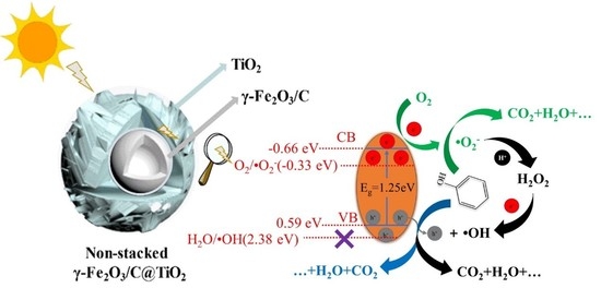
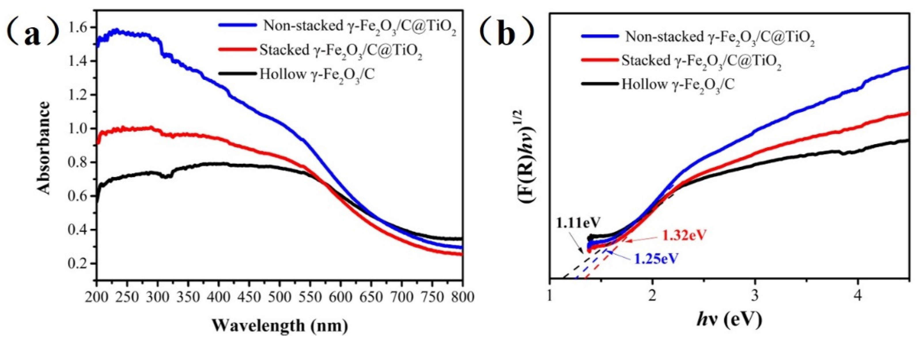
3.2. UV-Vis Absorbance Spectra of Non-Stacked γ-Fe2O3/C@TiO2

The optical absorption of TiO2 was affected by impurities and changes in the bandgap. The impact of catalysts’ overlap modes on the absorption of visible light was analyzed using UV-vis-DRS. Figure 6a shows that the three catalysts generated the absorption band-edge around 550 nm, corresponding to the transition of electrons from the top of the valence band to the footing of the conduction band. The absorption band edge did not immediately decline to 0 from 550 to 800 nm; however, it entered an extended buffer period, corresponding to the energy of photon needed to transition electrons from the O2p level to the impurity station. This extensive absorption range reflected the main characteristics of γ-Fe2O3/C.
From Figure 6b, the first maximum at 2.3 eV (540 nm) is associated with point lattice defects, namely oxygen vacancies, while the subsequent growth at energies above 2.3 eV corresponds to the fundamental bandgap [29,30]. The corresponding bandgap energies of non-stacked γ-Fe2O3/C@TiO2 and stacked γ-Fe2O3/C@TiO2 were 1.25 and 1.32 eV (Figure 6b), which were both higher than hollow γ-Fe2O3/C (1.11 eV). The band locations (Figure 7) were calculated using the XPS valence spectra and bandgap energies. The γ-Fe2O3/C exhibited a valence band (VB) at 0.08 eV and a conduction band (CB) at −1.03 eV. The CB and VB of stacked γ-Fe2O3/C@TiO2 and non-stacked γ-Fe2O3/C@TiO2 were notably different. According to previous literature, the shell affects the energy band depending on the material [31,32,33,34]. The TiO2 layer had a more positive conduction band voltage than γ-Fe2O3. The surface dipole layer formed by the TiO2 shell caused the conduction band voltage of the γ-Fe2O3 inner layer to migrate, and the migration direction and magnitude depended on the dipole parameters due to the usage of the two materials and the different stacking modes. Non-stacked γ-Fe2O3/C@TiO2 had a moderate band edge position (VB at 0.59 eV and CB at −0.66 eV). During the photodegradation of organic pollutants, the suitable band edge position enabled three active substances (·OH, ·O2−, holes) to function simultaneously.
The charge generation and charge transfer behaviors over non-stacked γ-Fe2O3/C@TiO2 are proposed in Scheme 1. Incident light can induce the transition of γ-Fe2O3. Excited electrons generated in γ-Fe2O3 can be efficiently transmitted to the conduction band of TiO2 through C species while holes remain in the valence band of γ-Fe2O3, resulting in effective electron-hole separation. Therefore, the bandgap will become smaller, and the excitation wavelength range of the TiO2 composite was expanded into the visible light region. From Scheme 1, the ·OH, ·O2− and holes will contribute to the degradation of organic matter, and the hydroxyl radicals are not obtained from hole oxidation of water but from the interaction of electrons, hydrogen ions, and superoxide radicals. And the production process of hydroxyl radical is as follows [11]:
e + O2 = ·O2
O2 + ·O2 + 2H+ = H2O2
H2O2 + e = ·OH + OH

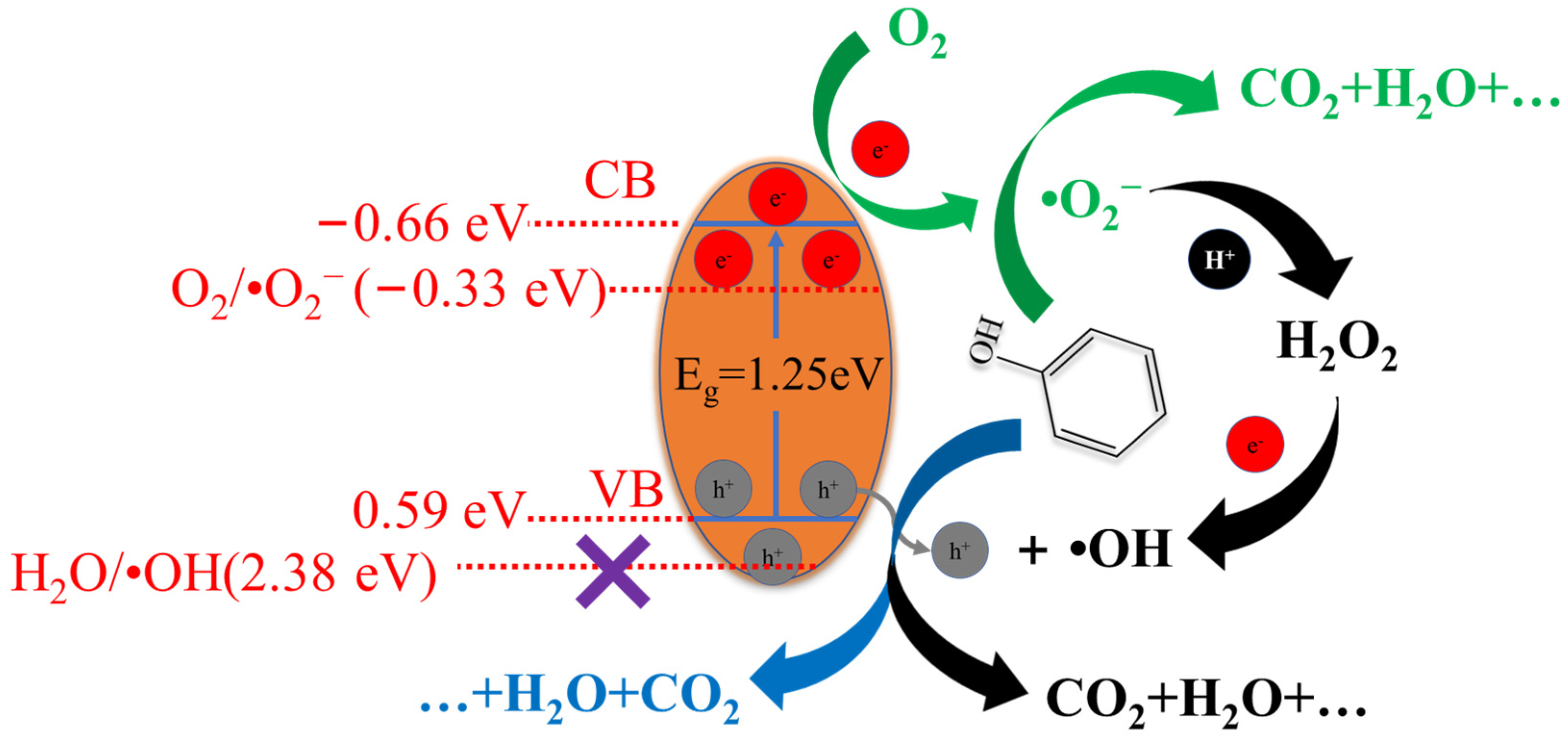
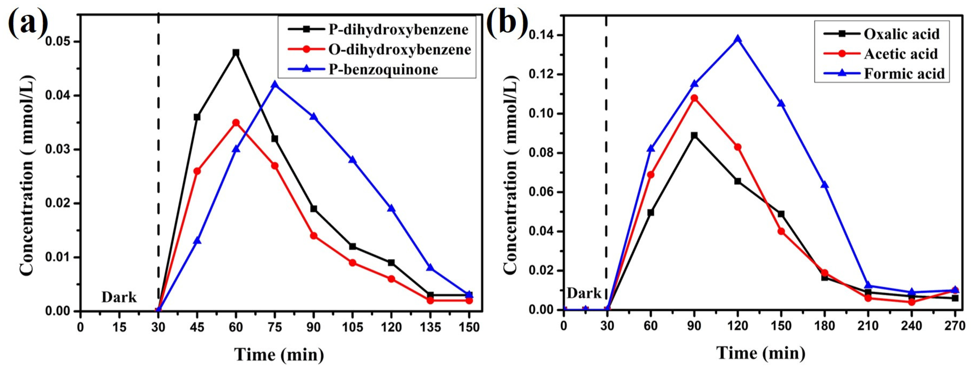
3.3. Photocatalytic Degradation of Phenol

Hollow γ-Fe2O3/C, stacked γ-Fe2O3/C@TiO2, and non-stacked γ-Fe2O3/C@TiO2 photocatalysts were used to degrade phenol under visible light irradiation. As shown in Figure 8a, non-stacked γ-Fe2O3/C@TiO2 showed the highest performance and thoroughly degraded phenol after 135 min of irradiation under Xe lamp with 300 W power (Figure 8b). The catalytic performance was as follows: non-stacked γ-Fe2O3/C@TiO2 > stacked γ-Fe2O3/C@TiO2 > hollow γ-Fe2O3/C. Compared with stacked γ-Fe2O3/C@TiO2, the performance of non-stacked γ-Fe2O3/C@TiO2 was significantly enhanced due to the unique designed morphology and structure, which can enhance the absorption capacity of visible light and improve the activity of adsorption sites. The hollow inner cavity also permitted the scattering and refraction of light; therefore, the diffusion distance of electron-hole pairs generated by light was reduced, maximizing light utilization. Simultaneously, the unique structure also expanded the specific surface area of the catalytic material. The carbon species can facilitate charge transfer from γ-Fe2O3 to the outer TiO2, reducing the recombination probability of photogenerated carriers. The reusability of non-stacked γ-Fe2O3/C@TiO2 was investigated (Figure S1), and the catalytic activity of the catalyst decreased by only about 5.0% after 5 catalytic cycles.
The degradation of phenol using the non-stacked γ-Fe2O3/C@TiO2 was analysed by UV-Vis absorbance spectra (Figure 9a) and in situ DRIFTS (Figure 9b). Interestingly, Figure 9a shows that the absorption band (269 nm) of phenol over non-stacked γ-Fe2O3/C@TiO2 substantially increased upon prolonging the irradiation time beyond 30 min, suggesting the formation of more intermediate products. When the irradiation time was prolonged, the intermediate products formed during the degradation of phenol decomposed to form small molecules, consistent with the results of in situ DRIFTS (Figure 9b). The absorption bands centered at 1410 cm−1 represented the stretching vibration of -OH functional group of phenol. The characteristic peaks of phenol significantly decreased when exposed to light after 30 min. This shows that the phenolic -OH was first oxidized during phenol degradation.
To further investigate the degradation of phenol over non-stacked γ-Fe2O3/C@TiO2, the intermediate products (p-dihydroxybenzene, o-dihydroxybenzene, p-benzoquinone, oxalic acid, acetic acid, and formic acid) were measured by high-performance liquid chromatography (Figure 10a,b). Under light irradiation, the holes formed by γ-Fe2O3/C@TiO2 reacted with phenol to generate unstable free radicals containing phenoxy groups. The o-and p-phenolic hydroxyl groups tend to form stable o-dihydroxybenzene, p-dihydroxybenzene, which were further oxidized to p-benzoquinone. Small molecules, such as oxalic acid, acetic acid, and formic acid, were formed through ring-opening and were eventually mineralized into CO2 and H2O. Non-stacked γ-Fe2O3/C@TiO2 had a moderate band edge position, allowing it to excite hydroxyl radicals, superoxide free radicals, and holes to oxidize organic compounds. This was ascribed to an appropriate overlap mode between the two layers. Moreover, Table 1 shows a comparison of the double-layer hollow nanoparticles with the other catalysts; it is found that the catalysts in this paper have better catalytic performance and can use fewer catalysts in a short time to achieve higher catalytic efficiency.

4. Conclusions

A facile route was used to synthesize non-stacked γ-Fe2O3/C@TiO2 double-layer hollow nanoparticles with appropriate overlap mode between the two layers. This unique material structure reduces the catalyst’s energy band, which can broaden the light response range to the visible light absorption range, and reduces the recombination rate of photogenerated carriers owing to the C moiety facilitated electron transfer from the γ-Fe2O3 moiety to TiO2. The non-stacked γ-Fe2O3/C@TiO2 displayed an excellent photocatalytic performance for phenol degradation under visible light irradiation, which is attributed to the cooperativity of the existence of ·OH, ·O2-, holes. In situ DRIFTS further explored the degradation pathway of phenol; during phenol degradation, -OH was first oxidized, and combined with the identification results of intermediate products, then the benzene rings were destroyed to form small molecule organic acid and eventually mineralized into CO2 and H2O. This overlap mode enhanced both charge generation and charge transfer over photocatalysts. The γ-Fe2O3 moiety endows the nano-shell with an ability of charge generation, while the C moiety facilitated electron transfer from the γ-Fe2O3 moiety to TiO2. The unique non-stacked double-layer structure inhibited the initial charge recombination in TiO2. The non-stacked γ-Fe2O3/C@TiO2 double-layer hollow nanoparticles can make the two steps of charge generation and charge transfer well-matched and synergistically enhanced, which significantly improved the efficiency of the photodegradation of phenol. The preparation of non-stacked γ-Fe2O3/C@TiO2 catalysts also provides a novel approach for the future design of a higher-efficiency photocatalytic system.

Supplementary Materials

The following supporting information can be downloaded at: https://www.mdpi.com/article/10.3390/nano12020201/s1, Figure S1: The lifetime of Non-stacked γ-Fe2O3/C@TiO2.

Author Contributions

Conceptualization, X.S., J.N., E.D., and Z.W.; methodology, X.S., Z.W., and J.N.; formal analysis, X.Y., H.S., Z.W., L.Z., and L.S.; investigation, X.S., Z.W., L.Z., H.S., H.Q., and J.S.; resources, X.S., L.S., and Z.W.; writing—original draft preparation, X.S., Z.W., J.S., and J.N.; writing—review and editing, Z.W., X.Y., X.S., H.Q. and E.D.; supervision, X.S., Z.W., and E.D.; project administration, X.S.; funding acquisition, X.S. All authors have read and agreed to the published version of the manuscript.

Funding

This work was financially supported by the National Natural Science Foundation of China (Grant: 21802117, 21904131) and Shandong Natural Science Foundation (Grant: ZR2019BB079).

Institutional Review Board Statement

Not applicable.

Informed Consent Statement

Not applicable.

Data Availability Statement

The data presented in this study are available on request from the corresponding author upon reasonable request.

Acknowledgments

A portion of this research used resources at the Collaborative Innovation Center of Light Hydrocarbon, and the Biomedical Research Center of the Northwest Minzu University. We thank Baisen Zeng from the Center for Biomolecular Structure and Dynamics for his help with this project and helpful discussions.

Conflicts of Interest

The authors declare no conflict of interest.

References

  1. Cao, T.T.; Xu, T.F.; Zhao, N.M.; Jiang, X.; Cui, C.W. Application of vacuum-ultraviolet (VUV) for phenolic homologues removal in humic acid solution: Efficiency, pathway and DFT calculation. J. Hazard. Mater. 2020, 384, 121464. [Google Scholar] [CrossRef]
  2. Busca, G.; Berardinelli, S.; Resini, C.; Arrighi, L. Technologies for the removal of phenol from fluid streams: A short review of recent developments. J. Hazard. Mater. 2008, 160, 265–288. [Google Scholar] [CrossRef]
  3. Ahmed, S.; Rasul, M.G.; Martens, W.N.; Brown, R.; Ashib, M.A.H. Heterogeneous photocatalytic degradation of phenols in wastewater: A review on current status and developments. Desalination 2010, 261, 3–18. [Google Scholar] [CrossRef] [Green Version]
  4. Qian, H.L.; Hou, Q.D.; Duan, E.H.; Niu, J.R.; Nie, Y.F.; Bai, C.Y.L.; Bai, X.Y.; Ju, M.T. Honeycombed Au@C-TiO2-Xcatalysts for enhanced photocatalytic mineralization of Acid red 3R under visible light. J. Hazard. Mater. 2020, 391, 122246. [Google Scholar] [CrossRef] [PubMed]
  5. Pal, U.; Sandoval, A.; Madrid, S.I.U.; Corro, G.; Sharma, V. Mohanty, Mixed titanium, silicon, and aluminum oxide nanostructures as novel adsorbent for removal of rhodamine 6G and methylene blue as cationic dyes from aqueous solution. Chemosphere 2016, 163, 142–152. [Google Scholar] [CrossRef] [PubMed]
  6. Streit, A.F.M.; Côrtes, L.N.; Druzian, S.P.; Godinho, M.; Collazzo, G.C.; Perondi, D.; Dotto, G.L. Development of high quality activated carbon from biological sludge and its application for dyes removal from aqueous solutions. Sci. Total Environ. 2019, 660, 277–287. [Google Scholar] [CrossRef]
  7. Oladipo, A.A.; Ifebajo, A.O.; Gazi, M. Magnetic LDH-based CoO–NiFe2O4 catalyst with enhanced performance and recyclability for efficient decolorization of azo dye via Fenton-like reactions. Appl. Catal. B Environ. 2019, 243, 243–252. [Google Scholar] [CrossRef]
  8. Amanulla, B.; Krishnan, D.; Vellaichamy, B.; Krishnan, N.P.; Chandran, M.; Ramaraj, S.K. Synthesis of highly efficient g-CN@CuO nanocomposite for photocatalytic degradation of phenol under visible light. J. Alloy. Compd. 2021, 886, 161167. [Google Scholar]
  9. Soheila, A.K.; Aziz, H.Y.; Kunio, Y. Novel g-C3N4 nanosheets/CDs/BiOCl photocatalysts with exceptional activity under visible light. J. Am. Ceram. Soc. 2019, 102, 1435–1453. [Google Scholar]
  10. Pan, X.; Yang, M.Q.; Fu, X.; Zhang, N.; Xu, Y.J. Defective TiO2 with oxygen vacancies: Synthesis, properties and photocatalytic applications. Nanoscale 2013, 5, 3601–3614. [Google Scholar] [CrossRef]
  11. Wu, Y.Y.; Ji, H.D.; Liu, Q.M.; Sun, Z.Y.; Li, P.S.; Ding, P.R.; Guo, M.; Yi, X.H.; Xu, W.L.; Wang, C.C.; et al. Visible light photocatalytic degradation of sulfanilamide enhanced by Mo doping of BiOBr nanoflowers. J. Hazard. Mater. 2022, 424, 127563. [Google Scholar] [CrossRef]
  12. Serga, V.; Burve, R.; Krumina, A.; Romanova, M.; Kotomin, E.A.; Popov, A.I. Extraction–pyrolytic method for TiO2 polymorphs production. Crystals 2021, 11, 431. [Google Scholar] [CrossRef]
  13. Zhang, W.Q.; Liu, H.; Liu, Z.C.; An, Y.H.; Zhong, Y.; Hu, Z.C.; Li, S.J.; Chen, Z.J.; Wang, S.G.; Sheng, X.L.; et al. Eu-dopedzeolitic imidazolate framework-8 modified mixed-crystal TiO2 for efficient removal of basic fuchsin from effluent. Materials 2021, 14, 7265. [Google Scholar] [CrossRef]
  14. Tsebriienko, T.; Popov, A.I. Effect of poly(Titanium Oxide) on the viscoelastic and thermophysical properties of interpenetrating polymer networks. Crystals 2021, 11, 794. [Google Scholar] [CrossRef]
  15. Shao, M.; Han, J.; Wei, M.; Evans, D.G.; Duan, X. The synthesis of hierarchical Zn–Ti layered double hydroxide for efficient visible-light photocatalysis. Chem. Eng. J. 2011, 168, 519–524. [Google Scholar] [CrossRef]
  16. Wang, Z.; Yang, B.; Zhao, X.Y.; Chen YSh Wei, D.D.; Zhang, L.J.; Su, X.T. Facile synthesis of ultrathin γ-Fe2O3 magnetic nanosheets rich in oxygen vacancies and their photocatalytic activity for water oxidation. Appl. Surf. Sci. 2022, 578, 151999. [Google Scholar] [CrossRef]
  17. Wang, X.; Zhou, J.; Zhao, S.; Chen, X.; Yu, Y. Synergistic effect of adsorption and visible-light photocatalysis for organic pollutant removal over BiVO4/carbon sphere nanocomposites. Appl. Surf. Sci. 2018, 453, 394–404. [Google Scholar] [CrossRef]
  18. Waghmode, T.R.; Kurade, M.B.; Sapkal, R.T.; Bhosale, C.H.; Jeon, B.-H.; Govindwar, S.P. Sequential photocatalysis and biological treatment for the enhanced degradation of the persistent azo dye methyl red. J. Hazard. Mater. 2019, 371, 115–122. [Google Scholar] [CrossRef]
  19. Nguyen, C.H.; Fu, C.-C.; Juang, R.-S. Degradation of methylene blue and methyl orange by palladium-doped TiO2 photocatalysis for water reuse: Efficiency and degradation pathways. J. Clean. Prod. 2018, 202, 413–427. [Google Scholar] [CrossRef]
  20. Li, W.; Deng, Y.H.; Wu, Z.X.; Qian, X.F.; Yang, J.P.; Wang, Y.; Gu, D.; Zhang, F.; Tu, B.; Zhao, D.Y. Hydrothermal etching assisted crystallization: A facile route to functional yolk-shell titanate microspheres with ultrathin nanosheets-assembled double shells. J. Am. Chem. Soc. 2011, 133, 15830–15833. [Google Scholar] [CrossRef]
  21. Xu, Y.; Ahmed, R.; Klein, D.; Cap, S.; Freedy, K.; McDonnell, S.; Zangari, G. Improving photo-oxidation activity of water by introducing Ti3+ in self-ordered TiO2 nanotube arrays treated with Ar/NH3. J. Power Sources 2019, 414, 242–249. [Google Scholar] [CrossRef]
  22. Zarrin, S.; Heshmatpour, F. Photocatalytic activity of TiO2/Nb2O5/PANI and TiO2/Nb2O5/RGO as new nanocomposites for degradation of organic pollutants. J. Hazard. Mater. 2018, 351, 147–159. [Google Scholar] [CrossRef]
  23. Sangjan, S.; Wisasa, K.; Deddeaw, N. Enhanced photodegradation of reactive blue dye using Ga and Gd as catalyst in reduced graphene oxide-based TiO2 composites. Mater. Today Proc. 2019, 6, 19–23. [Google Scholar] [CrossRef]
  24. Yin, L.; Gao, Y.J.; Jeon, I.; Yang, H.; Kim, J.-P.; Jeong, S.Y.; Cho, C.R. Rice-panicle-like γ-Fe2O3@C nanofibers as high-rate anodes for superior lithium-ion batteries. Chem. Eng. J. 2019, 356, 60–68. [Google Scholar] [CrossRef]
  25. Han, W.; Wang, L.; Li, Z.; Tang, H.; Li, Y.; Huo, C.; Lan, G.; Yang, X.; Liu, H. γ-Fe2O3 as the precursor of iron based catalyst prepared by solid-state reaction at room temperature for Fischer-Tropsch to olefins. Appl. Catal. A Gen. 2019, 572, 158–167. [Google Scholar] [CrossRef]
  26. Zeb, F.; Khan, M.S.; Nadeem, K.; Kamran, M.; Abbas, H.; Krenn, H.; Szabo, D.V. Reduced surface spin disorder in ZrO2 coated γ-Fe2O3 nanoparticles. Solid State Commun. 2018, 284–286, 69–74. [Google Scholar] [CrossRef]
  27. Pan, X.; Duan, X.; Lin, X.; Zong, F.; Tong, X.; Li, Q.; Wang, T. Rapid synthesis of Cr-doped γ-Fe2O3/reduced graphene oxide nanocomposites as high performance anode materials for lithium ion batteries. J. Alloys Compd. 2018, 732, 270–279. [Google Scholar] [CrossRef]
  28. Ibrahim, E.M.M.; Abdel-Rahman, L.H.; Abu-Dief, A.M.; Elshafaie, A.; Hamdan, S.K.; Ahmed, A.M. Electric, thermoelectric and magnetic characterization of γ-Fe2O3 and Co3O4 nanoparticles synthesized by facile thermal decomposition of metal-Schiff base complexes. Mater. Res. Bull. 2018, 99, 103–108. [Google Scholar] [CrossRef]
  29. Lushchik, A.; Feldbach, E.; Kotomin, E.A.; Kudryavtseva, I.; Kuzovkov, V.N.; Popov , A.I.; Seeman, V.; Shablonin, E. Distinctive features of diffusion controlled radiation defect recombination in stoichiometric magnesium aluminate spinel single crystals and ransparent polycrystalline ceramics. Sci. Rep. 2020, 10, 7810. [Google Scholar] [CrossRef]
  30. Mykhailovych, V.; Kanak, A.; Cojocaru, S.; Chitoiu-Arsene, E.; Palamaru, M.N.; Iordan, A.R.; Korovyanko, O.; Diaconu, A.; Ciobanu, V.G.; Caruntu, G.; et al. Structural, Optical, and Catalytic Properties of MgCr2O4 Spinel-Type Nanostructures Synthesized by Sol–Gel Auto-Combustion Method. Catalysts 2021, 11, 1476. [Google Scholar] [CrossRef]
  31. Rajkumar, S.; Prabaharan, M. Multi-functional core-shell Fe3O4@Au nanoparticles for cancer diagnosis and therapy. Colloids Surf. B Biointerfaces 2019, 174, 252–259. [Google Scholar]
  32. Li, P.; He, Z.; Luo, C.; Xiao, Y.; Wang, Y.; Hu, J.; Li, G.; Jiang, H.; Zhang, W. α-Fe2O3@dopamine core-shell nanocomposites and their highly enhanced photoacoustic performance. Appl. Surf. Sci. 2019, 466, 185–192. [Google Scholar] [CrossRef]
  33. Li, M.; Hu, Y.; Fang, Y.; Tan, T. Coating mesoporous ZSM-5 by thin microporous Silicalite-1 shell: Formation of core/shell structure, improved hydrothermal stability and outstanding catalytic performance. Catal. Today 2020, 339, 312–320. [Google Scholar] [CrossRef]
  34. Al-Fahdi, T.; Al Marzouqi, F.; Kuvarega, A.T.; Mamba, B.B.; Al Kindy, S.M.Z.; Kim, Y.; Selvaraj, R. Visible light active CdS@TiO2 core-shell nanostructures for the photodegradation of chlorophenols. J. Photochem. Photobiol. A Chem. 2019, 374, 75–83. [Google Scholar] [CrossRef]
  35. Zhang, J.; Du, Y.; Zhang, L.; Zheng, X.; Ma, Y.; Dong, S.; Zhou, D. Preparation of sponge carrier supported photocatalyst by self-assembly technique for phenol photodegradation in visible light. Mol. Catal. 2017, 432, 1–7. [Google Scholar] [CrossRef]
  36. Mohamed, M.A.; Salleh, W.N.W.; Jaafar, J.; Ismail, A.F.; Nor, N.A.M. Photodegradation of phenol by N-doped TiO2 anatase/rutile nanorods assembled microsphere under UV and visible light irradiation. Mater. Chem. Phys. 2015, 162, 113–123. [Google Scholar] [CrossRef]
  37. Zhang, Z.Y.; Zhao, C.C.; Duan, Y.S.; Wang, C.; Zhao, Z.C.; Wang, H.J.; Gao, Y.J. Phosphorus-doped TiO2 for visible light-driven oxidative coupling of benzyl amines and photodegradation of phenol. Appl. Surf. Sci. 2020, 527, 146693. [Google Scholar] [CrossRef]
  38. Yao, J.; Chen, H.; Jiang, F.; Jiao, Z.; Jin, M. Titanium dioxide and cadmium sulfide cosensitized graphitic carbon nitride nanosheets composite photocatalysts with superior performance in phenol degradation under visible-light irradiation. J. Colloid Interface Sci. 2017, 490, 154–162. [Google Scholar] [CrossRef]
  39. Wang, J.L.; W, B.; Xu, L.L.; Gao, H.; Sun, W.J.; Che, J.X. Multilayered MoS2 coated TiO2 hollow spheres for efficient photodegradation of phenol under visible light irradiation. Mater. Lett. 2016, 179, 42–46. [Google Scholar] [CrossRef] [Green Version]
Figure 1. Catalyst synthesis process.
Nanomaterials 12 00201 g001
Figure 2. XRD patterns of non-stacked γ-Fe2O3/C@TiO2 (a) and hollow γ-Fe2O3/C (b); Raman spectra (c) of non-stacked γ-Fe2O3/C@TiO2, stacked γ-Fe2O3/C@TiO2, and hollow γ-Fe2O3/C.
Nanomaterials 12 00201 g002
Figure 3. Pore size distribution (a) and N2 hysteresis curve (b) of non-stacked γ-Fe2O3/C@TiO2.
Nanomaterials 12 00201 g003
Figure 4. (a,b) the images of non-stacked γ-Fe2O3/C@TiO2; (a’c’) of the process of catalyst preparation, and (a’) the image of SiO2@γ-Fe2O3/C; (b’) the image of SiO2@γ-Fe2O3/C@SiO2@TiO2; (c’) the image of image of a single sphere of non-stacked γ-Fe2O3/C@TiO2; (d’) HRTEM images.
Nanomaterials 12 00201 g004
Figure 5. XPS Fe 2p spectrum (a), O1s inner shell (b), C1s (c), Ti2p (d), and O1s outer shell (e) for non-stacked γ-Fe2O3/C@TiO2.
Nanomaterials 12 00201 g005
Figure 6. UV-Vis diffuse reflectance spectra (a) and calculated band gap patterns based on UV-Vis diffuse reflectance spectra (b) of non-stacked γ-Fe2O3/C@TiO2, stacked γ-Fe2O3/C@TiO2, and hollow γ-Fe2O3/C.
Nanomaterials 12 00201 g006
Figure 7. Valance band XPS spectra of non-stacked γ-Fe2O3/C@TiO2, stacked γ-Fe2O3/C@TiO2, and hollow γ-Fe2O3/C.
Nanomaterials 12 00201 g007
Scheme 1. Schematic illustration of the non-stacked γ-Fe2O3/C@TiO2.
Nanomaterials 12 00201 sch001
Figure 8. Conversion (a) degradation of phenol and (TOC) (b) total organic carbon over non-stacked γ-Fe2O3/C@TiO2, stacked γ-Fe2O3/C@TiO2, and hollow γ-Fe2O3/C catalysts.
Nanomaterials 12 00201 g008
Figure 9. UV-Vis absorbance spectra (a), in situ DRIFTS (b) of phenol degradation over non-stacked γ-Fe2O3/C@TiO2.
Nanomaterials 12 00201 g009
Figure 10. Intermediate products (a,b) for phenol degradation over non-stacked γ-Fe2O3/C@TiO2.
Nanomaterials 12 00201 g010
Table 1. Comparison of catalyst performance.
Photo CatalystPhenolCharacteristics% Degradation
Er3+: YAlO3/TiO2: 0.39 g50 mgL−1Visible light58% (8 h) [35]
N-doped TiO2: 0.3 g50 mgL−1λ = 312 nm UV99.6% (540 min) [36]
2P-TiO2-500: 50 mg10 mgL−1Xenon lamp (300 W)100% (180 min) [37]
TiO2-CdS-gCNNSs: 50 mg10 mgL−1Visible light80% (300 min) [38]
TiO2/MoS2 heterostructures-Visible light78% (150 min) [39]
This work: 0.1 g20 mgL−1Visible lightAlmost 100% (135 min)
Publisher’s Note: MDPI stays neutral with regard to jurisdictional claims in published maps and institutional affiliations.

