Article

Improvement of Photocatalytic Performance by Building Multiple Heterojunction Structures of Anatase–Rutile/BiOI Composite Fibers

School of Mechanical Engineering, Yangzhou University, Yangzhou 225009, China
*
Authors to whom correspondence should be addressed.
Nanomaterials 2022, 12(21), 3906; https://doi.org/10.3390/nano12213906
Submission received: 11 October 2022 / Revised: 27 October 2022 / Accepted: 3 November 2022 / Published: 5 November 2022

Abstract

:
In this study, multiple heterojunction structures of anatase–rutile/Bismuth oxyiodide (BiOI) composite fibers are designed by the combined method of electrospinning and hydrothermal techniques. The influence of different Ti/Bi atomic ratios ([Ti/Bi]) on the nanostructures and photocatalytic properties are investigated. It is found that the morphology of BiOI covered on the TiO2 fiber surface changed with [Ti/Bi] from nanosheets to submicron spheres structures. Additionally, the crystallization of the composite fibers including the phases of anatase, rutile, and BiOI is identified, theses phases are in close contact with each other, and the interfacial effects are helpful to form the multiple heterojunctions which lead to blue shifts on the chemical state of Ti. The absorption of visible light has been improved by compositing BiOI on TiO2, while the band gap values of the composite fibers are significantly reduced, which can enhance the generation and separation of electrons and holes. For the case of [Ti/Bi] = 1.57, the photodegradation rate of anatase–rutile/BiOI composite fibers is about 12 times that of pure TiO2. For the photocatalytic mechanism, the synergistic s-type heterojunctions increase the content of active oxides which have a positive effect on the degradation rate.

1. Introduction

Over the past decade, with the acceleration of industrialization, more and more serious water pollution problems have aroused people’s concern [1]. In our country, many sewage treatment methods such as photocatalytic degradation [2], electrocatalytic degradation [3,4], adsorption [5], thin film technology [6], and biodegradation [7], etc., are adopted to solve the problems. Among them, photocatalytic materials are widely used, because these special materials can directly apply solar energy, and have the advantages of no secondary pollution and convenient recycling. In recent years, it has become the main research focus. Except for removing pollutants, photocatalysis can also be used to solve the problem of energy shortage [8]. However, many photocatalysts can only absorb UV light (accounting for only 4–5% of solar energy). As an n-type semiconductor, TiO2 is a widely used photocatalytic material [9] with the characteristics of biological inertia, strong oxidation, non-toxicity, and no light corrosion. However, TiO2 has a relatively wide band gap (~3.1 eV) [10], and its photocatalytic degradation ability can only be activated under the excitation of ultraviolet light, so the utilization rate of sunlight is low.
With the deepening of semiconductor research, its related technology has been applied in more and more different fields, and semiconductor composite scheme has also been applied in TiO2 modification technology by many scholars. In order to solve the problem of poor photocatalytic activity of TiO2, the most commonly used methods are ion doping [11], surface modification [12], and semiconductor composite [13]. Semiconductor composite heterojunction formation is widely concerned as an effective method to improve photocatalytic activity. Compared with the single-phase photocatalyst, the formation of a polyheterojunction structure will increase the absorption of ultraviolet and visible light and increase the separation efficiency of photoelectrons and holes. This is because when one kind of semiconductor is combined with another kind of semiconductor, the small bandgap semiconductor absorbs a large amount of sunlight as a photosensitizer, and the photoelectrons on the stimulated small bandgap semiconductor surface can be transferred to another semiconductor, which effectively separates the photogenerated electrons from the holes and greatly improves the efficiency of photocatalysis [14]. In recent years, compounds such as bismuth halooxide BiOX (X = Cl, Br, I) have come into the view of researchers [15]. BiOX is generally used as ferroelectric materials and pigments, but studies have found that BiOX has good visible light and ultraviolet photocatalytic activity [16]. Compared with other bismuth halides, BiOCl has a relatively high band gap between 3.22 eV and 3.50 eV. Band gaps of BiOBr and BiOI are about 1.77 eV and 1.74 eV, respectively, which mainly absorb visible light [17]. Among new semiconductor photocatalysts, BiOI has a tetragonal crystal structure, is soluble in hydrochloric acid, insoluble in water, alcohol, etc., which has become a research hotspot because of its stable chemical properties, layered structure, non-toxic and low cost. However, BiOI is not perfect, its valence band is not positive enough, the separation efficiency of photogenerated electron holes is low, and micro-nanoparticles are prone to agglomeration, which is difficult to be recycled and reused [18,19,20,21]. So, due to the advantages and shortages of pure TiO2 and BiOX, some researchers have tried to mix these two materials to produce photocatalysts with high degradation efficiency. In the literature, it is found that the TiO2/BiOI p-n heterojunction can really improve the photocatalytic activity in the visible light wavelength range compared with the single BiOX and TiO2 phase [22,23,24]. Zhang et al. [25] synthesized TiO2-X/BiOI heterojunction by a simple hydrothermal synthesis method, its photocatalytic ability was characterized by the rate of H2 production to verify the utilization of light, which is higher than that produced by original material.
However, people also have to face the problems in practical applications as follows, (i) the powder recovery is difficult, and it is easy to cause secondary pollution; (ii) the reaction time is long, and large-scale applications cannot be realized. In order to solve the above defects, it is of great significance to fix the semiconductor photocatalyst on the carrier. Carriers such as fibers, porous nickel foam, stainless steel mesh, and porous sponge are highly valued because of their large comparative area and skeleton-like three-dimensional network structure. Among them, the fibers of semiconductor materials fabricated by the electrospinning processes have been proven to exhibit improved functional performance [26,27,28,29,30]. The technical parameters of electrospinning can be well-tuned to produce fibers with modified morphologies and mixed nanostructures. Some researchers have made studies concerning the electrospinning of oxide materials and the application of fiber materials in photocatalysis. T. Salehi et al. [26] fabricated a hybrid ZnO nanofiber/reduced graphene oxide gas sensor by electrospinning process, which showed a linear response to gas. S. Jian et al. [30] found that La-doped ZnO nanofibers were successfully fabricated via electrospinning–calcination technology, these catalysts were more efficient in rhodamine B degradation than undoped ZnO after 510 min illumination under visible light. The composite fibers were found to be stable and reusable and had potential in the management of rhodamine B dye wastewater. Meanwhile, for the photocatalysts with mixed phases, the building of multiple heterojunctions or generating some chemical defects should be more helpful to enhance the photocatalytic properties. So, how to design the multiple phases or defects involved in the composite materials and use these interfacial effects to build multiple heterojunctions should be meaningful in future experiments for researchers. This kind of photocatalyst may have great advantages and broad prospects compared to powdered catalysts.
The purpose of this study is to build multiple heterojunction structures in the photocatalysts with mixed phases of TiO2/BiOI composites. Especially for the synthesis process, the combined method of electrospinning and hydrothermal techniques is designed to in situ grow BiOI on the TiO2 fiber and make a further determination on what ratio of TiO2 and BiOI can have the best photocatalytic performance. The photocatalytic efficiency of TiO2/BiOI composite fiber was evaluated by MO degradation by visible light. Moreover, the phase tuning, Ti/Bi atomic ratio, and interfacial effects on the heterojunction structures and photocatalytic performance were studied. The related kinetics of degradation and photocatalytic mechanisms were investigated. The process in this study is simple and low in cost, which is expected to become a new method to improve the photocatalytic performance of semiconductor materials.

2. Materials and Methods

2.1. Materials

Cetyltrimethyl ammonium bromide (C16H33(CH3)3NBr) (CTAB), tetranyl titanate (C16H36O4Ti) (TBOT), bismuth nitrate pentachrystalline (Bi(NO3)3·5H2O), methyl orange (C14H14N3NaO3S) (MO) and ethylene glycol (EG) were purchased from Sinopharm Reagent Chemical Group Co., LTD (Shanghai, China). The absolute ethanol is from Shanghai Lingfeng Chemical Reagent Co., LTD (Shanghai, China). Acetic acid (CH3COOH) was purchased from Jiangsu Functional Chemical Co., LTD (Suzhou, China). Polyvinylpyrrolidone (PVP) was provided by Aladdin Reagent (Shanghai) Co., LTD (Shanghai, China). The purity of all reagents was above 99.7% and could be used directly in subsequent experiments. All the water used in the experiment was made by deionizing water production.

2.2. Electrospinning and Annealing of TiO2 Fibers

In this study, the TiO2 fibers were first produced by electrospinning technology, and then the crystal structure of the fiber was regulated by heat treatment process. In the first step of spinning solution preparation, 60 g of absolute ethanol and 3 g of acetic acid were thoroughly mixed, and then 30 g of CTAB and 5 g PVP were added and stirred on magnetic stirrer for 20 min. Then, 20 g TBOT was slowly added after completely dissolving, and continued stirring until the solution is clear and transparent. When the solution appears viscous state, 10 mL was absorbed with a syringe and placed in homemade electrospinning equipment, then high voltage static electricity was applied to the liquid through 15 KV high voltage direct current. The pump speed of the homemade electrospinning machine is 1 mL/h, using an 18 # spinning needle (the outer diameter of the needle is 1.2 mm). A high voltage direct current of 15 KV was applied between the needle and the receiving plate, and the distance between the needle and the receiving plate was kept at 15 cm to ensure uniform electric field intensity. The needle was mounted on a numerical control device and reciprocated laterally at a rate of 5 cm/s, and the reciprocating movement has a period of 40 cm (in Figure 1). The fibers were spun continuously for 9 h. Under the action of electric field [31,32], charged polymer droplets can overcome the surface tension and shoot out in the form of jet stream. After the jet stream is ejected, the solvent in it will evaporate or solidify. Then, part of the solute will be deposited on the receiving device to form nonwovens such as fiber mat. The textile fiber thickness is about 200–300 nm. Finally, the prepared fibers were calcined in a Muffle furnace at 700 °C for 2 h, and then cooled naturally to room temperature with the furnace.

2.3. Synthesis of TiO2/BiOI Composite Fibers

During the experiment, 40 mL of ethylene glycol (EG) solution was added to three beakers, respectively. In order to prepare TiO2/BiOI composites with different proportions, 1.2/2.4/4.8 mmol Bi(NO3)3·5H2O was separately added to the beaker containing EG solution above, and the mixture was thoroughly mixed by magnetic stirrer. Then, 1.2/2.4/4.8 mmol of KI was separately injected, after stirring for 0.5 h, the mixed solution was poured into three reaction kettles with Teflon resin as the inner tank. At the same time, 1.2 mmol of calcined TiO2 fibers was added into the reaction kettle, and then the three-reaction kettle was put into the drying oven. The hydrothermal synthesis temperature was selected at 130 °C, and the holding time was 6 h. After the reactor is cooled to room temperature, discard the solution and precipitated powder in the reactor, take out the composite fiber, clean it with ethanol, and put it into the drying oven for drying at 70 °C. The obtained TiO2/BiOI composite fibers were sequentially labeled as T/B-1 (molar mass ratio 1:1), T/B-2 (molar mass ratio 1:2), and T/B-3 (molar mass ratio 1:4).

2.4. Structural Characterization

Scanning electron microscopy (FE-SEM, Hitachi S-4800II) (Hitachi, Japan) was used to study and analyze the morphology of the prepared samples. High-resolution TEM (HRTEM, Tecnai G2 F30 S-Twin) (FEI, Hillsboro, OR, USA) was used to characterize the samples at the nanoscale. The crystallization of samples was observed and characterized using D8 Advance polycrystalline X-ray diffractometer equipment (Bruker, Karlsruhe, Germany). Each sample was scanned at a speed of 0.5°/min. The valence and content of the elements were analyzed and characterized by XPS (ESCALAB 250Xi) (Thermo Scientific, Waltham, MA, USA). A Cary 5000 UV–VIS–NIR absorption spectrometer (VArian, Palo Alto, CA, USA) was used to characterize the absorbance of the samples in order to obtain the range of light absorption. The degradation efficiency of the photocatalyst was studied by electrochemical experiments on the prepared photocatalyst samples at CHI 660B workstation.

2.5. Photocatalytic Degradation Test

Photocatalytic performance test and analysis using the GHX-3 type photocatalytic reaction instrument purchased from Yangzhou University Science and Education City Instrument Co., Ltd (Yangzhou, China). and UV 752 type UV–visible photometer (Shanghai Yidang Analysis Co., LTD., Shanghai, China). In this study, methyl orange indicator was used as the simulated pollutant in dye wastewater, and the residual amount of methyl orange was determined by testing the absorption ability of residual methyl orange to 464 nm wavelength light. The organic wastewater simulated by methyl orange was prepared by adding 25 mg methyl orange indicator to 1000 mL deionized water at room temperature and pressure, so as to prepare 25 ppm methyl orange solution (MO).
In the photocatalytic performance test, 20 mg photocatalyst was added to the 400 mL quartz bottle of the photocatalytic reactor, and 100 mL MO solution with a concentration of 25 ppm was added to obtain the mixed suspension. Leave the suspension in the dark and turn on the magnetic force of the device for 30 min to achieve adsorption–desorption balance. Then, the 250 W xenon lamp (color temperature 6000 k) equipped with the device was turned on to irradiate the prepared suspension to simulate the visible light irradiation environment. The spacing between the light source and the sample was 8 cm. During irradiation, cooling water is supplied to the cooling water jacket of the quartz photocatalytic bottle through an external cooling water pipe. The temperature of the suspension was maintained at approximately 25 °C by cooling water, and 5 mL of the suspension was taken every 30 min. The degradation efficiency of the photocatalyst was tested by setting the reference absorbance value of 464 nm on UV–vis spectrophotometer.

3. Results

3.1. Morphologies and Crystallization

The microscopic morphologies of TiO2, T/B-1, T/B-2, and T/B-3 fibers were characterized by scanning electron microscopy (Figure 2). For pure TiO2 fibers, which were arranged in disorder, showing a fluffy state, the fiber surface was smooth and clean without any impurity deposition and composite (Figure 2a). The diameter of the main body is between 200 and 400 nm, and there are a few microfibers less than 100 nm, it is caused by the instability of Taylor cone during electrospinning. The morphologies of TiO2/BiOI composite fibers with different Ti/Bi atomic ratios are shown in Figure 2b–d. For the sample of T/B-1, it can be observed that only a small amount of BiOI in clusters of nanosheets grown inhomogeneous on the surface of TiO2 fibers. With the increase in the concentration of Bi-containing precursor during solvothermal synthesis, the BiOI content on the surface of TiO2 fiber is constantly increased, more and more fiber surface is covered. The growth of BiOI on T/B-2 was relatively uniform, but the morphology was gradually changed to that of submicron spheres. For the sample of T/B-3, the morphology shows that the surface of TiO2 fiber is basically completely covered, and a large number of complete submicron spheres appeared.
Therefore, according to the above SEM observations, it can be concluded that during the solvothermal synthesis process, the BiOI morphology in situ grown on the TiO2 fiber surface evolved with the Ti/Bi atomic ratio in the precursor solution. It changed from nanosheets to submicron spheres structures, and the fiber surface can be totally covered by BiOI when the molar mass ratio of Ti/Bi was set at 1:4 in the precursor solution.
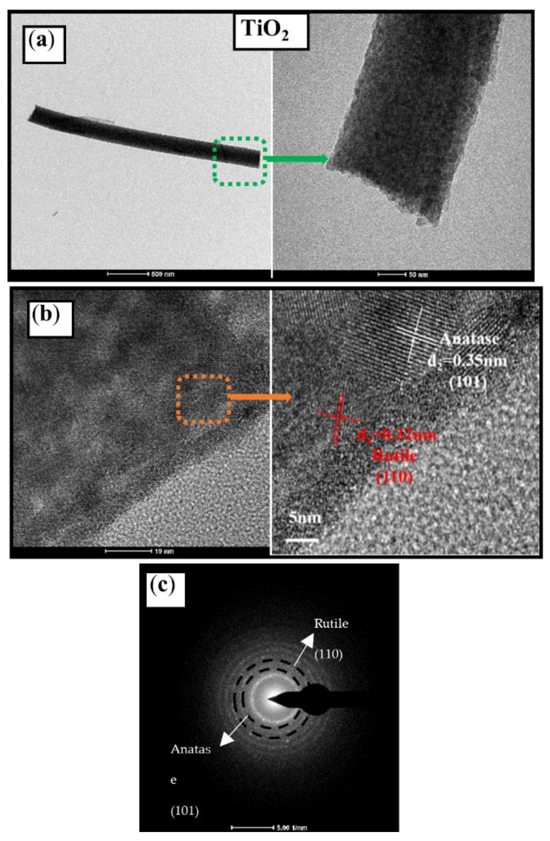
In order to further study the microstructure and crystal structure, pure TiO2 and T/B-2 were analyzed in detail by TEM. In Figure 3a, it can be observed that the surface of pure TiO2 is flat, smooth, and compact, and there is no impurity attachment. For pure TiO2 samples, HRTEM (Figure 3b) and diffraction pattern (Figure 3c) was used to measure and analyze. It is found that the prepared TiO2 fiber exhibits a polycrystalline state after calcination at 700 °C, and the lattice spacing indicates that this polycrystalline state consists of anatase phase (0.35 nm) and rutile phase (0.32 nm). This is due to the different cooling rates at different locations of the fibers after calcination. It is further found that the two-phase structures are adjacent to each other and easy to form heterojunction structures, which may have a positive effect on photocatalytic behavior.
For the T/B-2 composite fiber, Figure 4a clearly shows that the flocculant distribution on the surface of TiO2 fiber is uniform. This is the BiOI nanosheet cluster growing on the TiO2 surface, and these nanosheets bind tightly to the fiber surface. HRTEM image (Figure 4b) shows that the heterojunction structure formed by the BiOI phase with lattice spacing of 0.3 nm and the anatase phase with lattice spacing of 0.35 nm [33] which should greatly improve the photocatalytic efficiency of composite fibers. Through the calibration of diffraction patterns at different positions (Figure 4c), the existence of TiO2 crystal phases (anatase and rutile) and BiOI crystal phases can also be found. EDX (Figure 4d) was further used to analyze the elemental composition of anatase–rutile/BiOI composite fiber. The test results indicated that the T/B-2 sample contains only Ti, O, Bi, and I, indicating that there was no contamination of other impurities in the process of sample preparation.
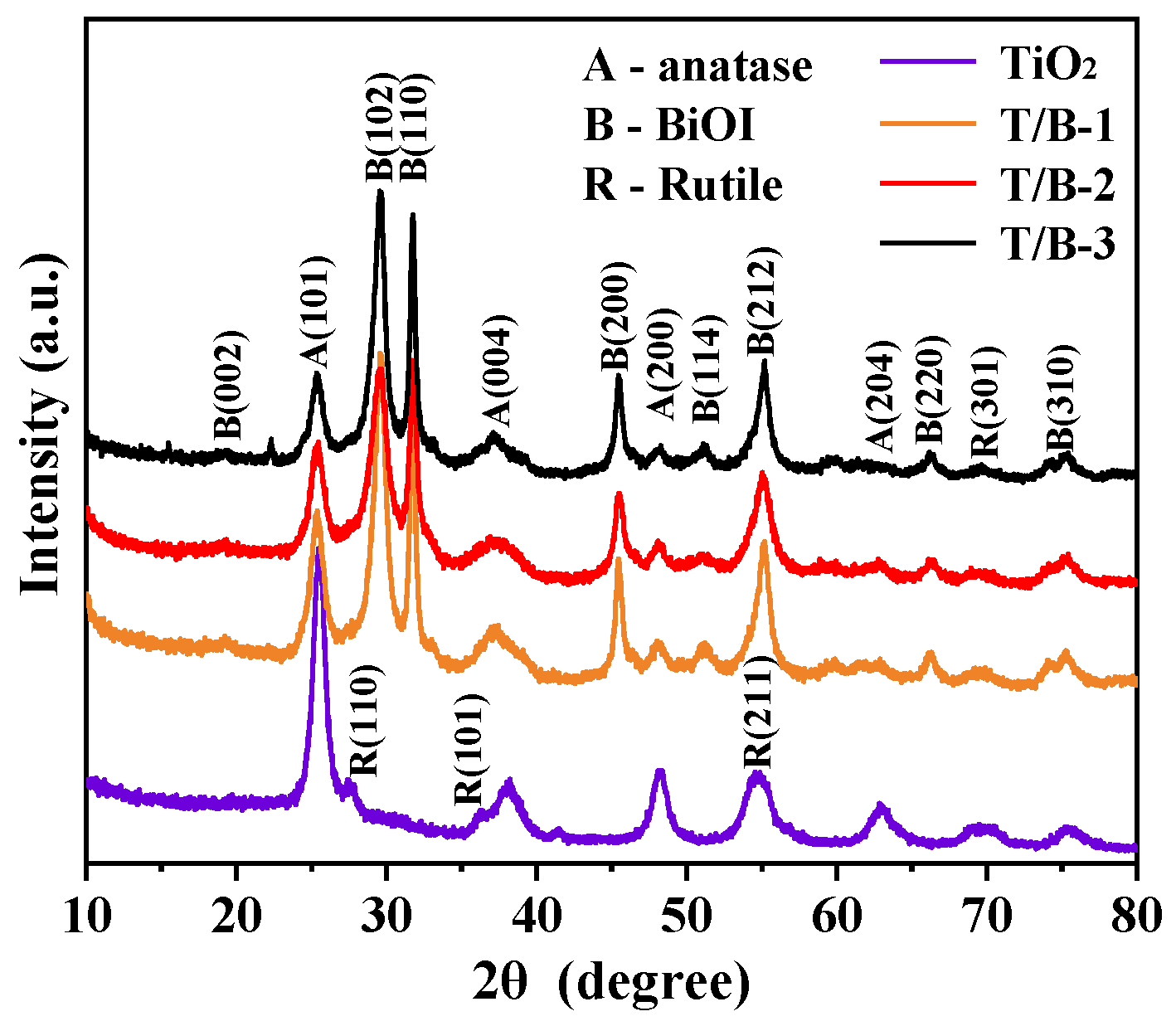
The XRD patterns of all samples are shown in Figure 5. For the crystal structure of pure TiO2 fiber, the anatase phase and a small amount of rutile phase are found, which is consistent with the TEM results. The anatase phase is mainly located around 25.8°, 37.8°, 48.0°, and 62.7°, corresponding to (101), (004), (200), and (204) crystals, respectively [34]. Rutile phase is mainly located at 27.4°, 36.1°, 54.3°, and 69.0°, corresponding to (110), (101), (211), and (301) crystal planes, respectively [35], and no diffraction peaks of other impurities are detected.
The XRD results of composite fibers with different proportions of BiOI and TiO2 show that only two characteristic peaks of BiOI and TiO2 phases can be identified, and no other new substances were generated. For the measured BiOI diffraction peak signals located at 19.3°, 29.6°, 31.6°, 45.3°, 55.1°, 51.3°, 66.1°, and 75.1°, corresponding to crystal planes (002), (102), (110), (200), (212), (114), (220), and (310), respectively, this matches well with the phase of BiOI (PDF#10-0445) [36]. This indicates that BiOI has been successfully synthesized on TiO2. With the continuous increase in BiOI concentration, the phases of TiO2 anatase and rutile gradually weakened, and the fibers were basically covered, which was consistent with the morphology observed by SEM.
From the above analysis, it can be basically judged that when the concentration of BiOI precursor reaches the composite condition of T/B-2, a relatively good composite morphology is formed. In order to further confirm the generation of heterojunction structures, Raman test is needed to detect TiO2, T/B-1, T/B-2, and T/B-3 fibers, the results are shown in Figure 6.
The Raman active modes of anatase of TiO2 are located around 145 cm−1 (Eg), 394 cm−1 (B1g), 518 cm−1 (A1g), and 639 cm−1 (Eg), respectively [37]. Raman spectra of pure TiO2 samples can prove that it has the characteristics of the anatase phase. With the increase in the concentration of BiOI on TiO2, the Eg characteristic peak of TiO2 in composite fiber gradually weakened, which means that the shading effect of the BiOI nanosheet cluster on TiO2 fiber was enhanced. However, when the precursor ratio of TiO2 to BiOI is 1:2, the peak value of T/B-2 rises again, because BiOI can be well compounded on TiO2 fiber when the ratio of TiO2 to BiOI was 1:2. The submicron sheet clusters would not interfere with each other, and TiO2 should not be excessively shaded by BiOI, which can be observed by SEM images. With the increase in the concentration of BiOI, the Eg characteristic peak of TiO2 at 143 cm−1 has a red shift to 141.3 cm−1, and the Eg peak at 636.3 cm−1 has a blue shift to 638.1 cm−1, this indicates that the lattice structure of TiO2 has been distorted [38], and lattice distortion is the main factor for the generation of heterojunctions.
From the above crystallization analysis, it is concluded that the phases of anatase, rutile, and BiOI have been identified in the composite fibers, while these phases are in close contact with each other. So, the interfacial effect should be helpful to form the anatase–rutile/BiOI multiple heterojunctions in the photocatalysis of mixed-phase TiO2/BiOI.

3.2. Chemical Structure

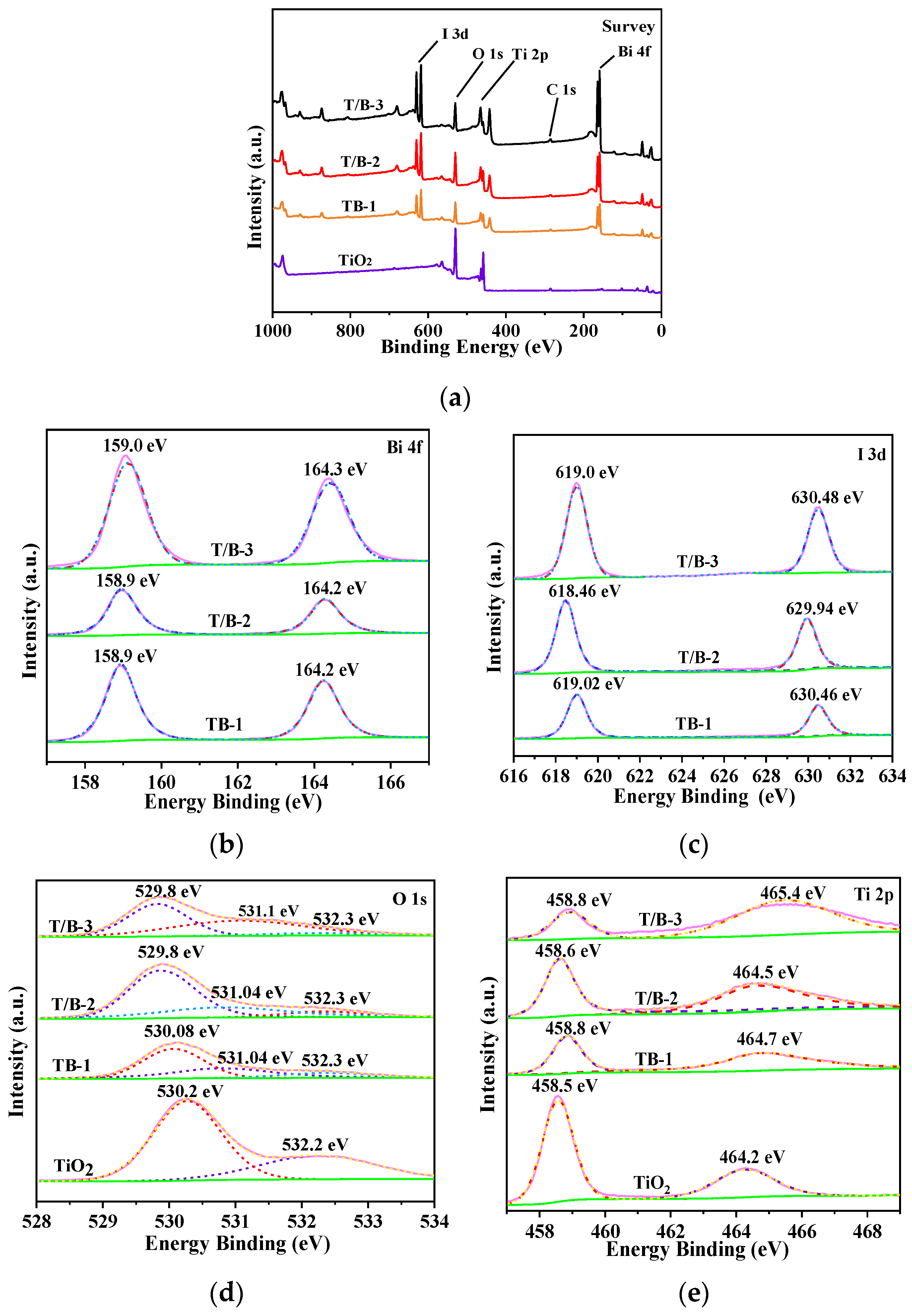
The chemical element composition and chemical bonding state of TiO2, T/B-1, T/B-2, and T/B-3 fibers were analyzed and tested by XPS. Ti, Bi, O, and I can all be verified in the XPS survey curves in Figure 7a. The element contents of the four samples are shown in Table 1. In the full spectrum of XPS (Figure 7a), it can be identified that the pure TiO2 fiber surface is only a Ti peak and O peak, there is no other impurity peak.
With the continuous addition of BiOI, Bi and I peaks appeared, and the peaks of Bi and I gradually increased. The characteristics of Bi+ in BiOI can be observed in the detailed XPS spectrograms of Bi 4F (Figure 7b), namely the Bi 4F7/2 peak near 158.9 eV and the Bi 4F5/2 peak near 164.3 eV [39]. In Figure 7c, the peaks of I 3d5/2 and I 3d3/2 binding energies are located around 618.7 eV and 630.2 eV, respectively, which also obviously reflects that I is from BiOI [40]. Figure 7d shows that the peaks corresponding to 530.2 eV and 532.2 eV before recombination are characteristic peaks of Ti-O and H2O, respectively. The three peaks formed after recombination are Ti-O (around 529.8 eV), Bi-O (around 531.1 eV), and O-H (532.3 eV) [41]. In Figure 7e, The peak of Ti 2P1/2 is located near 464.4 eV and Ti 2p3/4 is located near 458.6 eV, which proves the existence of Ti4+ [42]. After recombination, the peak of Ti 2P1/2 shifts to the direction of higher binding energy by at most 1.3 eV, which again proves the formation of a heterojunction structure. It can be found from Table 1 that with the continuous increase in BiOI concentration, the content of the Ti element decreased significantly, while the content of the Bi element gradually increased, and the value of Ti/Bi decreased significantly, which was consistent with the situation observed by SEM and XRD.
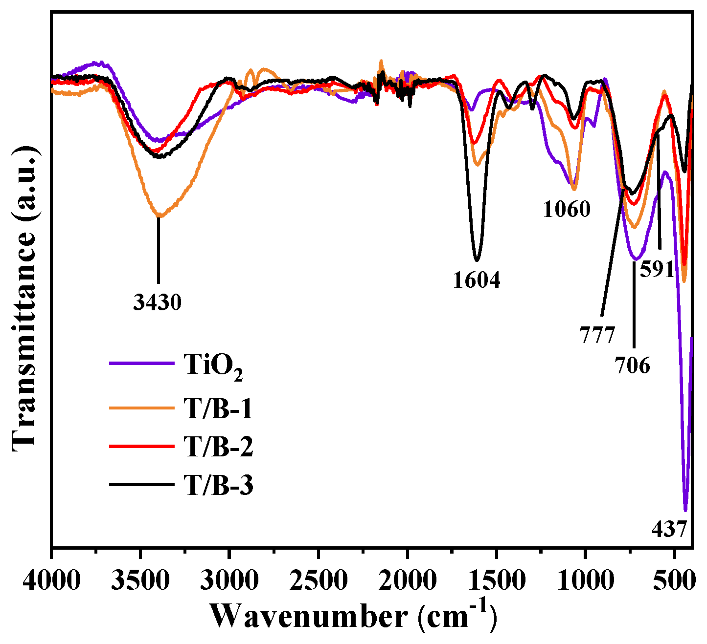
Subsequently, FTIR spectroscopy was used to characterize the chemical structure of TiO2, T/B-1, T/B-2, and T/B-3 fibers, as shown in Figure 8. In the TiO2 spectrum, the peak width in the wide frequency band of 500–800 cm−1 corresponds to the peak produced by the Ti-O-Ti bending vibration of TiO2. A total of 1604 cm−1 and 3430 cm−1 are caused by the bending vibration of adsorbed H2O and -OH. The peak at 3000 cm−1 is caused by the presence of O-H [43,44]. With the addition of BiOI and the continuous increase in compound concentration, the characteristic peak of the anatase phase at 437 cm−1 was hidden with the increase in the number of BiOI nanosheet clusters, and the peak intensity decreased significantly. The polar hydroxyl group (-OH) attached to the heterojunction between TiO2 and BiOI was vibrating, so the characteristic peak at 1604 cm−1 was significantly enhanced [45]. The characteristic peak at 1051 cm−1 is the wide peak centered by the vibration of the Ti–OH bond. As BiOI continues to attach to TiO2 fibers, the shading effect is enhanced, the fracture peak width of the Ti–OH bond is narrowed [46], and there is an obvious blue shift, which is influenced by the heterojunction between TiO2 and BiOI. This is consistent with the TEM observation (Figure 4b).

3.3. Calculation of UV–Vis Spectra and Bandgaps

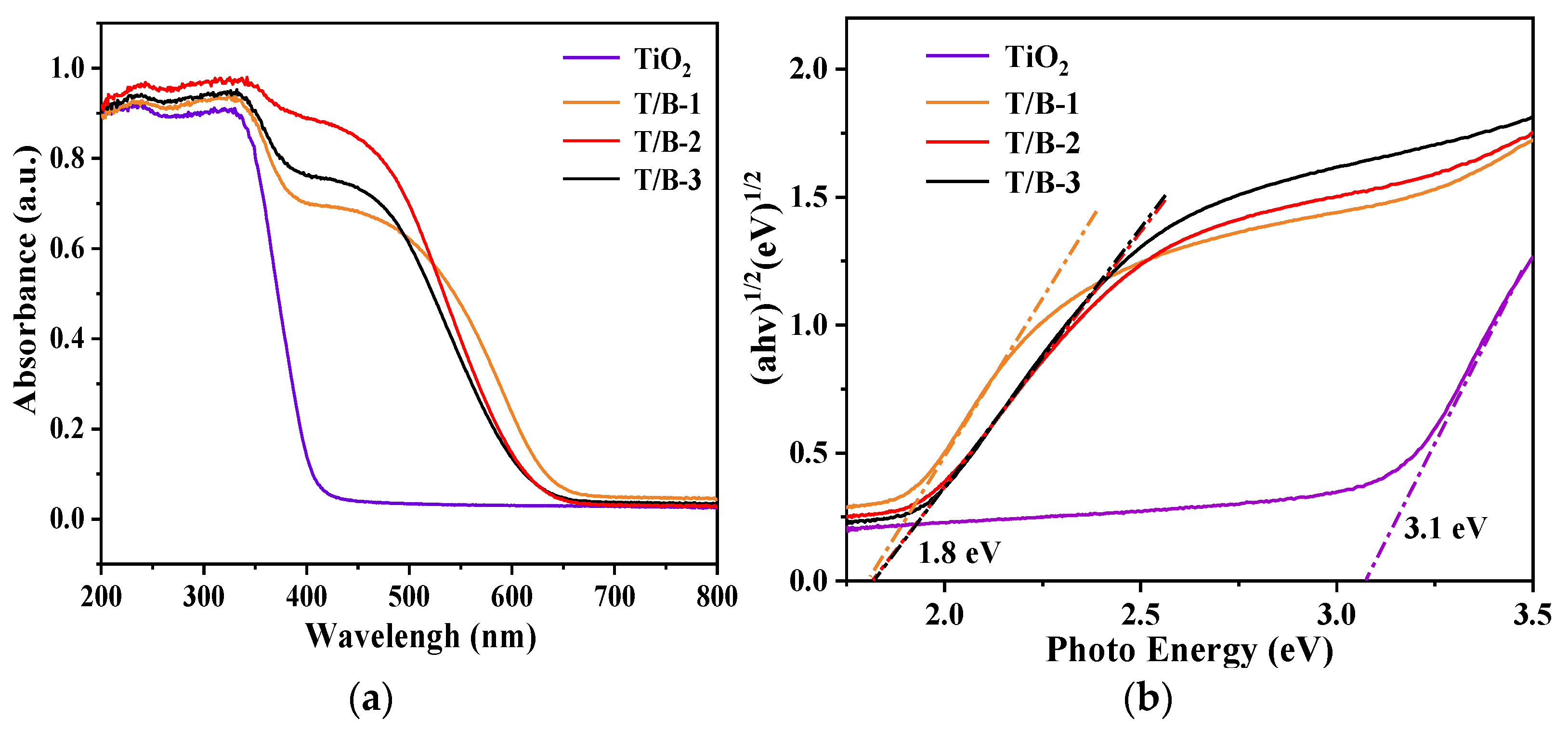
An important factor affecting the absorption performance of semiconductors is the width of the band gap. The narrower the band gap, the wider the absorption range. UV–vis absorption was used to test TiO2, T/B-1, T/B-2, and T/B-3 fibers, and the absorption curves were shown in Figure 9a. However, in the visible light wavelength range, it can be found that TiO2 fiber almost does not absorb. When BiOI was compounded on the surface of TiO2, heterojunction was formed, and the absorption of visible light was significantly improved. It indicates that TiO2-BiOI interfacial effect leads to a low band gap value. This is because of the unique multilayer structure of BiOI, which still has some unpaired electrons inside. Free electron binding on the surface of TiO2 may lead to the formation of, for example, a Ti–O–Bi bond, which makes the valence band move up. Finally, the composite fiber appears to have a smaller band gap [47].
The following reference formula is often used to calculate the optical bandgap of photocatalysts:(ahν)1/n = C(hν − Eg) [48], BiOI is an indirect bandgap semiconductor with index n = 2 [49]. The calculated band gap value is shown in Figure 9b. The Eg value of TiO2 is 3.1 eV, and the values for T/B-1, T/B-2, and T/B-3 are all around 1.8 eV. Obviously, compared with pure TiO2 fiber, the band gap values of the composite fibers are significantly reduced, which is helpful to generate more photogenerated carriers and has a great impact on the improvement of photocatalytic efficiency.

3.4. Photocatalytic Performance Test

The degradation capacity of TiO2, T/B-1, T/B-2, and T/B-3 fibers was simulated by using methyl orange solution in a photocatalytic reactor. Figure 10a shows the degradation capacity of different fibers. It can be observed that pure TiO2 fiber has the most unsatisfactory degradation effect on methyl orange solution, the T/B-2 composite fiber has the best degradation rate (reached 54%), and the degradation rate of T/B-3 was slightly lower than that of T/B-2, which may be caused by the inability of TiO2 fiber to absorb more photogenerated electrons from BiOI. Although T/B-1 composite fiber has a narrow band gap, it is not effective in photocatalytic test, this may be attributed to the fragility of BiOI in the form of micron sheets, during the photocatalytic test, BiOI was impacted by water flow, and the heterojunction [50] could not work normally.
The photocatalytic performance of the prepared composite in this work is compared with the experimental results of other authors (in Table 2), it can be seen that the prepared anatase–rutile/BiOI composite fibers have better degradation efficiency relative to the recent literature review on TiO2/BiOI photocatalysts. In order to further explore the optical absorption properties of TiO2, T/B-1, T/B-2, and T/B-3 fibers, empirical formulas were used to fit the measured data [51,52]. Figure 10b shows that the degradation rate constant K values of TiO2, T/B-1, T/B-2, and T/B-3 fibers are 0.00058, 0.00375, 0.00624, and 0.00411 min−1, respectively. The photodegradation rate of T/B-2 is higher than that of other fibers, about 12 times that of pure TiO2. This is because the obtained band gap is narrow, and the electron holes are not easy to aggregate.
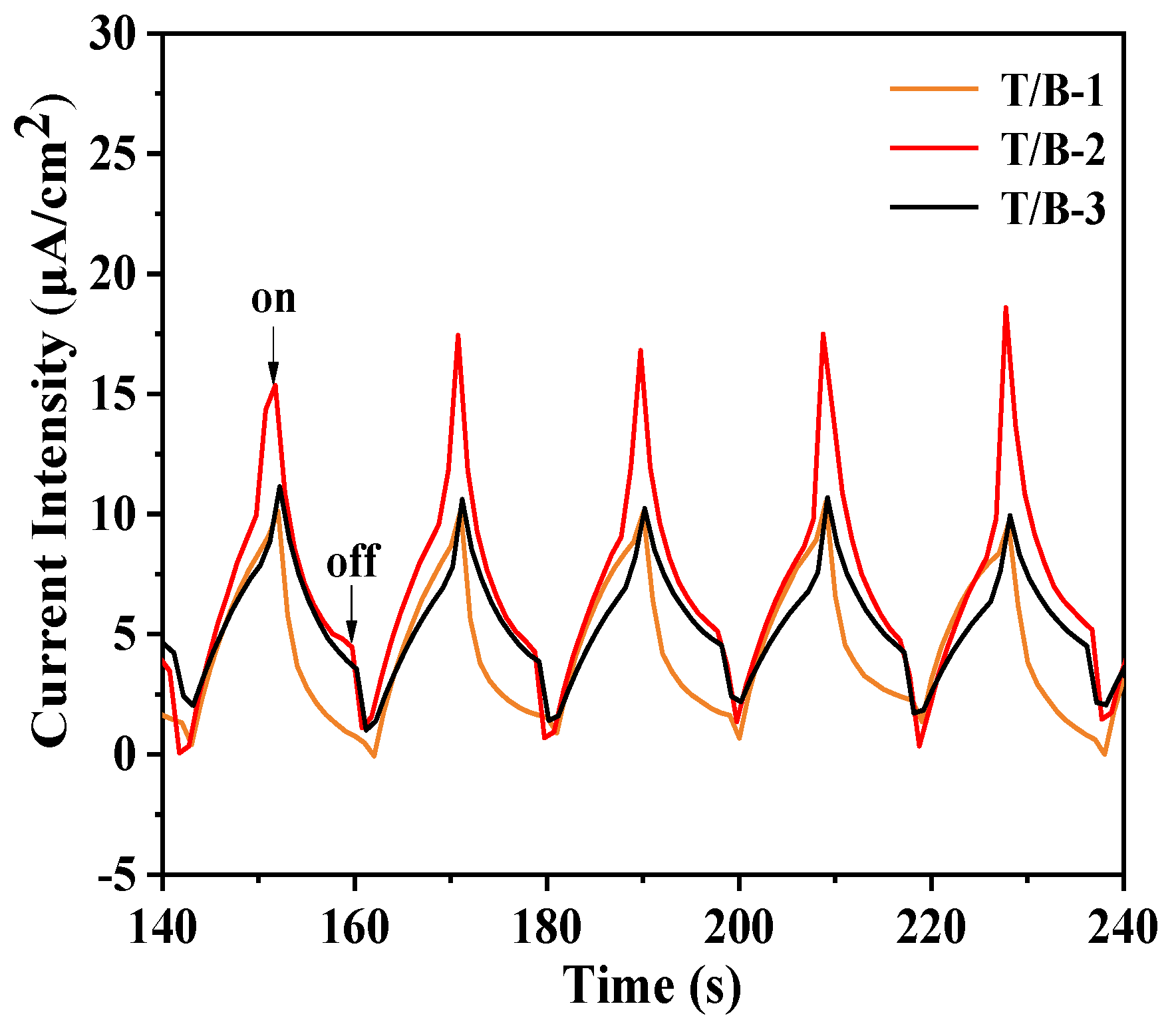
In the experiment, the photocurrent test method was also used to characterize the separation efficiency of electron holes, as shown in Figure 11. The detected T/B-1, T/B-2, and T/B-3 composite fibers all had photocurrent responses, and the value of T/B-2 was found to be increased obviously. The results show that when the composite precursor ratio is 1:2, the charge transfer efficiency of the sample is higher, which well proves the accuracy of the experimental results of photocatalytic degradation.
Briefly, the degradation reaction of methyl orange is through the excitation of photogenerated electrons and band gaps, and the holes generated after excitation react with pollutants. Moreover, the direction of electron transfer between TiO2/BiOI photocatalyst is determined by the conduction band (CB) and valence band (VB) of BiOI and TiO2. However, CB and VB of BiOI and TiO2 need to be calculated by the following formula [56]:
EVB = X − EC + 0.5Eg
ECB = EVB − Eg
where X represents the absolute electronegativity of semiconductor photocatalytic materials, Ec is the free electron energy under hydrogen label. Eg stands for bandgap value, which is obtained from the UV–Vis test. The band gap values for BiOI, anatase TiO2, and rutile TiO2 were 1.74 eV, 3.1 eV, and 3.0 eV, respectively. Table 3 shows the CB and VB values of BiOI, anatase TiO2, and rutile TiO2, respectively.
It can be seen that the TiO2 fiber surface attached to BiOI can reduce the band gap value. Therefore, it is easy to generate more photogenerated electrons and holes under simulated sunlight, which is conducive to improving the photocatalytic ability of pure TiO2 under sunlight.
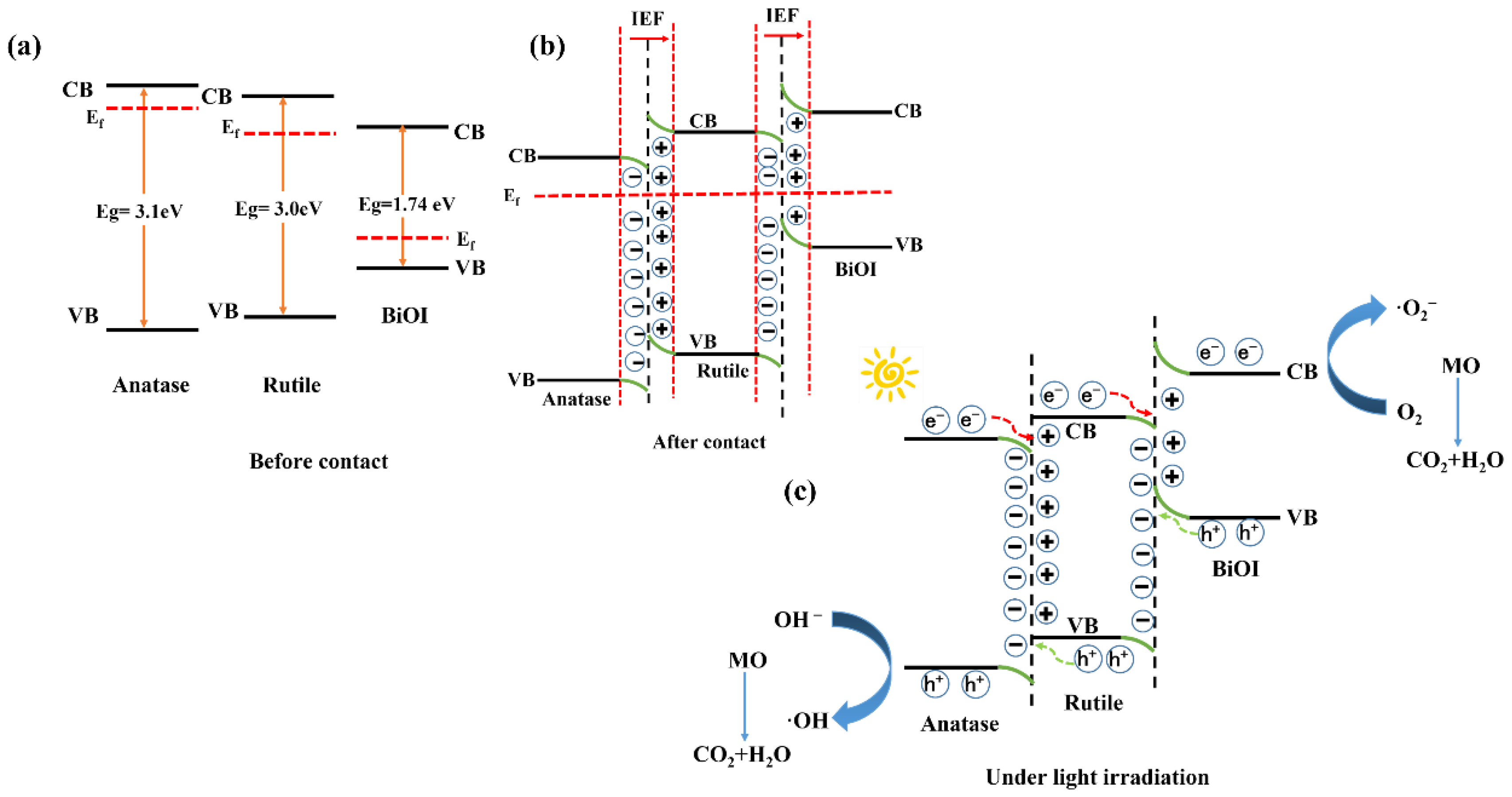
Based on the above analysis, anatase–rutile/BiOI conforms to the charge transfer process of S-type heterojunction structure, as shown in Figure 12 [57]. Before contact, the CB and Fermi levels of rutile TiO2 and anatase TiO2 are above BiOI. The work function (Φ) of rutile TiO2, anatase TiO2, and BiOI are calculated using empirical function V = Φ − φ [58,59]. V represents the contact potential difference and φ is the work function of the XPS test instrument itself. After calculation, the work functions of rutile TiO2, anatase TiO2, and BiOI are 6.31 eV, 6.51 eV, and 8.57 eV, respectively. The work function is inversely proportional to the Fermi level. Fermi energy levels of rutile TiO2 and anatase TiO2 are close. BiOI with the maximum work function has the lowest Fermi energy level, as shown in Figure 12a. When anatase TiO2 and rutile TiO2, rutile TiO2 and BiOI are in full contact [60], Fermi level can reach equilibrium. At this time, the work functions of rutile TiO2, anatase TiO2, and BiOI change to 6.22 eV, e on BiOI will spontaneously diffuse to the surface of TiO2 and form the accumulation layer and consumption layer of e on the surface (Figure 12b) [61]. At the same time, an IEF is generated at the contact point. In the process of contact (Figure 12c), The Fermi levels of anatase TiO2, rutile TiO2, and BiOI move up and down, respectively, which is the fundamental reason for the band bending up and down. IEF, coulomb force, and band bending will recombine photogenerated electrons with holes, and IEF also plays a role in accelerating the combination. This improves the efficiency of anatase–rutile/BiOI photocatalysis.
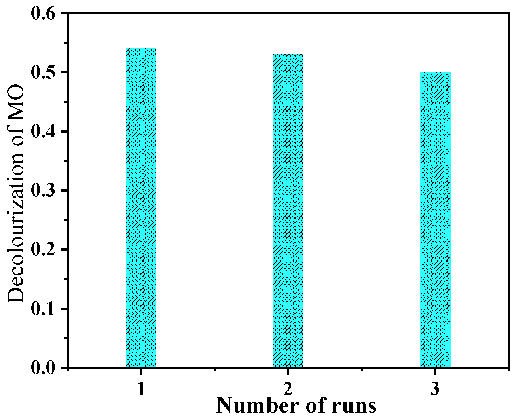
Subsequently, we tested the photocatalytic results of the T/B-2 composite fibers after recycling (in Figure 13). First, the composite fibers were filtered from MO solution and rinsed repeatedly with absolute ethanol and deionized water. Then, put the rinsed fibers into the drying box to dry them again. After that, the photocatalytic test was carried out for 150 min and repeated twice. The results show that the degradation efficiencies of the first two times are not changed so much, the performance is slightly reduced in the third cycle, which may be due to the shedding of BiOI caused by water flushes.

4. Conclusions

In summary, BiOI was successfully synthesized on the surface of TiO2 fiber by the combination of electrospinning and hydrothermal synthesis processes. The study concerning the Ti/Bi atomic ratio of TiO2/BiOI composite fiber on the nanostructures and related photocatalytic performance was conducted. Variable morphologies of the composite fibers have been obtained according to [Ti/Bi], which is changed from nanosheets to submicron spheres structures, and the fiber surface can be totally covered by BiOI when the molar mass ratio of Ti/Bi was set at 1:4 in the precursor solution. The crystallization including anatase, rutile, and BiOI has been evidenced, and the chemical state of the Ti element was shifted for interfacial effects which should be helpful to form the anatase–rutile/BiOI multiple heterojunctions in the photocatalysis of mixed-phase TiO2/BiOI. The photocatalytic activity of the synthesized TiO2/BiOI composite fiber was improved 10~300% compared with the results from the literature, it also can reach about 12 times the degradation efficiency of the original TiO2 fiber. This should be caused by the formation of multiple heterojunction structures of anatase–rutile/BiOI composite fibers. The multiple heterojunction structures have enhanced the absorption of visible light and reduced the band gap value, which leads to the increase in photocurrent. Moreover, the S-type heterojunction mechanism is supposed to increase the degradation rate under visible light irradiation, which induces the separation of photogenerated electrons and holes. The process in this study is simple and low in cost, which is expected to become a new method to improve the photocatalytic performance of semiconductor materials.

Author Contributions

Formal analysis, D.L. and K.X.; Funding acquisition, D.L.; Supervision, D.L.; Writing—original draft, D.L. and K.X.; Writing—review & editing, D.L. and C.Z. All authors have read and agreed to the published version of the manuscript.

Funding

This research was funded by the National Natural Science Foundation of China (51602279 and 32072785), the Qinglan Project of Jiangsu Province of China (2020), JiangSu Province Scientific and Technological Project (BZ2022043).

Institutional Review Board Statement

Not applicable.

Informed Consent Statement

Not applicable.

Data Availability Statement

The data presented in this study are available on request from the corresponding author.

Conflicts of Interest

The authors declare no conflict of interest.

References

  1. Ivanuša, M.; Kumer, B.; Petrovčič, E.; Štular, D.; Zorc, M.; Jerman, I.; Gorjanc, M.; Tomšič, B.; Simončič, B. Eco-Friendly Approach to Produce Durable Multifunctional Cotton Fibres Using TiO2, ZnO and Ag NPs. Nanomaterials 2022, 12, 3140. [Google Scholar] [CrossRef] [PubMed]
  2. Čop, K.T.; Pavlović, D.; Kraljević, T. Photocatalytic Activity of TiO2 for the Degradation of Anticancer Drugs. Nanomaterials 2022, 12, 3532. [Google Scholar]
  3. Zhang, L.; Hu, Z.; Huang, J.; Chen, Z.; Li, X.; Feng, Z.; Yang, H.; Huang, S.; Luo, R. Experimental and DFT studies of flower-like Ni-doped Mo2C on carbon fiber paper: A highly efficient and robust HER electrocatalyst modulated by Ni(NO3)2 concentration. J. Adv. Ceram. 2022, 11, 1294–1306. [Google Scholar] [CrossRef]
  4. Zhang, L.; Huang, J.; Hu, Z.; Li, X.; Ding, T.; Hou, X.; Chen, Z.; Ye, Z.; Luo, R. Ni(NO3)2-induced high electrocatalytic hydrogen evolution performance of self-supported fold-like WC coating on carbon fiber paper prepared through molten salt method. Electrochim. Acta 2022, 422, 140553. [Google Scholar] [CrossRef]
  5. Khaliha, S.; Marforio, T.; Kovtun, A.; Mantovani, S.; Bianchi, A.; Navacchia, M.L.; Zambianchi, M.; Bocchi, L.; Boulanger, N.; Iakunkov, A.; et al. Defective graphene nanosheets for drinking water purification: Adsorption mechanism, performance, and recovery. Flat. Chem. 2021, 29, 100283. [Google Scholar] [CrossRef]
  6. Zhao, H.; Zhang, D.; Sun, H.; Zhao, Y.; Xied, M. Adsorption and detection of heavy metals fromaqueous water by PVDF/A TP-CDs composite membrane. Coll. Oid. Surface. A 2022, 641, 128573. [Google Scholar] [CrossRef]
  7. Frankowski, R.; Płatkiewicz, J.; Stanisz, E.; Grześkowiak, T.; Zgoła-Grześkowiak, A. Biodegradation and photo-Fenton degradation of bisphenol A, bisphenol S and fluconazole in water. Environ. Pollut. 2021, 289, 117947. [Google Scholar] [CrossRef]
  8. Babu, S.J.; Muniyappa, M.; Rao, V.N.; Mudike, R.; Shastri, M.; Tathagata, S.; Shivaramu, P.D.; Shankar, M.V.; Kumar, C.S.A.; Rangappa, D. Enhanced photocatalytic hydrogen evolution from reduced graphene oxide-defect rich TiO2-x nanocomposites. Int. J. Hydorgen Energ. 2022, in press.
  9. Alhaddad, M.; Ismail, A.A.; Alghamdi, Y.G.; Al-Khathami, N.D.; Mohamed, R.M. Co3O4 Nanoparticles Accommodated Mesoporous TiO2 framework as an Excellent Photocatalyst with Enhanced Photocatalytic Properties. Opt. Mater. 2022, 131, 112643. [Google Scholar] [CrossRef]
  10. Shen, H.; Zhang, W.; Guo, C.; Zhu, J.; Cui, J.; Xue, Z.; Chen, P. Natural Cotton Cellulose-Supported TiO2 Quantum Dots for the Highly Efficient Photocatalytic Degradation of Dyes. Nanomaterials 2022, 12, 3130. [Google Scholar] [CrossRef]
  11. Rutherford, B.X.; Dou, H.; Zhang, B.; He, Z.; Barnard, J.P.; Paldi, R.L.; Wang, H. Single-Step Fabrication of Au-Fe-BaTiO3 Nanocomposite Thin Films Embedded with Non-Equilibrium Au-Fe Alloyed Nanostructures. Nanomaterials 2022, 12, 3460. [Google Scholar] [CrossRef]
  12. Wang, N.; Li, J.; Lv, W.; Feng, J.; Yan, W. Synthesis of polyaniline/TiO2 composite with excellent adsorption performance on acid red G. RSC Adv. 2015, 5, 21132. [Google Scholar] [CrossRef]
  13. Bakhtiar, A.; Bouberka, Z.; Roussel, P.; Volkringer, C.; Addad, A.; Ouddane, B.; Pierlot, C.; Maschke, U. Development of a TiO2/Sepiolite Photocatalyst for the Degradation of a Persistent Organic Pollutant in Aqueous Solution. Nanomaterials 2022, 12, 3313. [Google Scholar] [CrossRef]
  14. Batista, W.V.F.C.; Cunha, R.; Santos, A.C.; Reis, P.M.; Furtado, C.A.; Silva, M.C.; Gorgulho, H.F. Synthesis of a reusable magnetic photocatalyst based on carbon xerogel/TiO2 composites and its application on acetaminophen degradation. Ceram. Int. 2022, in press.
  15. Zuarez-Chamba, M.; Tuba-Guamán, D.; Quishpe, M.; Vizuete, K.; Debut, A.; Herrera-Robledoa, M. Photocatalytic degradation of bisphenol A on BiOI nanostructured films under visible LED light irradiation. J. Photoch. Photobio. A 2022, 431, 114021. [Google Scholar] [CrossRef]
  16. Guan, Y.; Wu, J.; Hu, B.; Lin, Y.; Liu, Q.; Zhang, H.; Xiao, Y.; Huang, J.; Mao, X.; Zhao, S. Fabrication of flower-like BiOI/Bi5O7I heterojunction photocatalyst by pH adjustment method for enhancing photocatalytic performance. Mater. Lett. 2019, 250, 202–205. [Google Scholar] [CrossRef]
  17. Chen, Y.; Huang, J.; Zhong, J.; Li, M.; Li, Z.; Yang, C. Enhanced photocatalytic performance of TiO2/BiOI heterojunctions benefited from effective separation of photogenerated carriers. Chem. Phys. Lett. 2021, 780, 138966. [Google Scholar] [CrossRef]
  18. Shakeri, M.; Delavari, H.H.; Montazerabadi, A.; Yourdkhani, A. Hyaluronic acid-coated ultrasmall BiOI nanoparticles as a potentially targeted contrast agent for X-ray computed tomography. Int. J. Biol. Macromol. 2022, 217, 668–676. [Google Scholar] [CrossRef]
  19. Liao, X.; Li, T.; Ren, H.; Zhang, X.; Shen, B.; Lin, J.; Lou, C. Construction of BiOI/TiO2 flexible and hierarchical S-scheme heterojunction nanofibers membranes for visible-light-driven photocatalytic pollutants degradation. Sci. Total. Environ. 2022, 806, 150698. [Google Scholar] [CrossRef]
  20. Luo, S.; Chen, J.; Huang, Z.; Liu, C.; Fang, M. Photocatalytic selective hydroxylation of phenol to dihydroxybenzene by BiOI/TiO2 p-n heterojunction photocatalysts for enhanced photocatalytic activity. ChemCatChem 2016, 8, 3780–3789. [Google Scholar] [CrossRef]
  21. Li, S.; Hu, S.; Xu, K.; Jiang, W.; Liu, J.; Wang, Z. A Novel Heterostructure of BiOI Nanosheets Anchored onto MWCNTs with Excellent Visible-Light Photocatalytic Activity. Nanomaterials 2017, 7, 22. [Google Scholar] [CrossRef] [Green Version]
  22. Zhang, G.; Ji, S.; Zhang, Y.; Wei, Y. Facile synthesis of p-n heterojunction of phosphorus doped TiO2 and BiOI with enhanced visible-light photocatalytic activity. Soild. State Commun. 2017, 259, 34–39. [Google Scholar] [CrossRef]
  23. Zhang, C.; Chen, W.; Hu, D.; Xie, H.; Song, Y.; Luo, B.; Fang, Y.; Gao, W.; Zhong, Z. Design and in-situ construct BiOI/Bi/TiO2 photocatalysts with metal-mediated heterostructures employing oxygen vacancies in TiO2 nanosheets. Green Energy Environ. 2022, 7, 680–690. [Google Scholar] [CrossRef]
  24. Qiu, J.; Dai, D.; Zhang, L.; Zhou, Y.; Yang, L.; Yao, J. Inlaying metal-organic framework derived pancake-like TiO2 into three-dimensional BiOI for visible-light-driven generation of vanillin from sodium lignosulfonate. J. Colloid Interf. Sci. 2022, 605, 648–656. [Google Scholar] [CrossRef]
  25. Zhang, B.; Wang, D.; Jiao, S.; Xu, Z.; Liu, Y.; Zhao, C.; Pan, J.; Liu, D.; Liu, G.; Jiang, B.; et al. TiO2-X mesoporous nanospheres/BiOI nanosheets S-scheme heterostructure for high efficiency, stable and unbiased photaocatalytic hydrogen production. Chem. Eng. J. 2022, 446, 137138. [Google Scholar] [CrossRef]
  26. Salehi, T.; Taherizadeh, A.; Bahrami, A.; Allafchian, A.; Ghafarinia, V. Towards a Highly Functional Hybrid ZnO Nanofiber-rGO Gas Sensor. Adv. Eng. Mater. 2020, 22, 2000005. [Google Scholar] [CrossRef]
  27. Çinar, B.; Kerïmoğlu, I.; Tönbül, B.; Demïrbüken, A.; Dursun, S.; Kaya, I.C.; Kalem, V.; Akyildiz, H. Hydrothermal/electrospinning synthesis of CuO plate-like particles/TiO2 fibers heterostructures for high-efficiency photocatalytic degradation of organic dyes and phenolic pollutants. Mat. Sci. Semicon. Proc. 2020, 109, 104919. [Google Scholar] [CrossRef]
  28. Xu, B.; Wang, X.; Huang, Y.; Liu, J.; Wang, D.; Feng, S.; Huang, X.; Wang, H. Electrospinning preparation of PAN/TiO2/PANI hybrid fiber membrane with highly selective adsorption and photocatalytic regeneration properties. Chem. Eng. J. 2020, 399, 125749. [Google Scholar]
  29. Zhang, J.; Kai, C.; Zhang, F.; Wang, Y. Novel PAN/Bi2MoO6/Ti3C2 ternary composite membrane via electrospinning with enhanced photocatalytic degradation of tetracycline. Colloid. Surface A 2022, 648, 129255. [Google Scholar] [CrossRef]
  30. Jian, S.; Tian, Z.; Hu, J.; Zhang, K.; Zhang, L.; Duan, G.; Yang, W.; Jiang, S. Enhanced visible light photocatalytic efficiency of La-doped ZnO nanofibers via electrospinning-calcination technology. Adv. Powder. Mater. 2022, 1, 1000004. [Google Scholar]
  31. Chen, L.; Liang, Z.; Li, L. Force analysis of unstable section of electrostatic spinning charged jet. J. King Saud. Univ. Sci. 2019, 31, 1528–1534. [Google Scholar] [CrossRef]
  32. Zhang, T.; Xu, H.; Zhang, Y.; Zhang, S.; Yang, X.; Wei, Y.; Huang, D.; Lian, X. Fabrication and characterization of double-layer asymmetric dressing through electrostatic spinning and 3D printing for skin wound repair. Mater. Design 2022, 218, 110711. [Google Scholar] [CrossRef]
  33. Zhang, Y.; Sun, A.; Xiong, M.; Macharia, D.K.; Liu, J.; Chen, Z.; Li, M.; Zhang, L. TiO2/BiOI p-n junction-decorated carbon fibers as weavable photocatalyst with UV–vis photoresponsive for efficiently degrading various pollutants. Chem. Eng. J. 2021, 415, 129019. [Google Scholar] [CrossRef]
  34. Yang, L.; Wang, R.; Zhou, N.; Jiang, L.; Liu, H.; He, Q.; Deng, C.; Chu, D.; Zhang, M.; Sun, Z. Construction of p-n heterostructured BiOI/TiO2 nanosheets arrays for improved photoelectrochemical water splitting performance. Appl. Surf. Sci. 2022, 601, 154277. [Google Scholar] [CrossRef]
  35. Debnath, K.; Majumder, T.; Mondal, S.P. Photoelectrochemical study of hydrothermally grown vertically aligned rutile TiO2 nanorods. Chem. Phys. 2022, 561, 111609. [Google Scholar] [CrossRef]
  36. Liu, Y.; Zhang, A.; Zhang, Q.; Mei, Y.; Wang, C.; Wang, Y.; Xiang, J.; Su, S.; Zhang, X.; Tan, Z. Facile synthesis of ternary AgBr/BiOI/Bi2O2CO3 heterostructures via BiOI self-sacrifice for efficient photocatalytic removal of gaseous mercury. Sep. Purif. Technol. 2022, 299, 121722. [Google Scholar] [CrossRef]
  37. Wang, H.; Chen, L.; Su, W.; Chung, J. Effect of the Compact TiO2 Layer on Charge Transfer between N3 Dyes and TiO2 Investigated by Raman Spectroscopy. J. Phys. Chem. C. 2010, 114, 3185–3189. [Google Scholar] [CrossRef]
  38. Karunadasa, K.S.P.; Manoratne, C.H. Microstructural view of anatase to rutile phase transformation examined by in-situ high-temperature X-ray powder diffraction. J. Solid State Chem. 2022, 314, 123377. [Google Scholar] [CrossRef]
  39. Jin, Y.; Li, C.; Zhang, Y. Preparation and visible-light driven photocatalytic activity of the rGO/TiO2/BiOI heterostructure for methyl orange degradation. New. Carbon Mater. 2022, 35, 394–400. [Google Scholar] [CrossRef]
  40. Bullen, J.; Lapinee, C.; Miller, L.; Bullough, F.; Berry, A.; Najorka, J.; Cibin, G.; Vilar, R.; Weiss, D. Spectroscopic (XAS, FTIR) investigations into arsenic adsorption onto TiO2/Fe2O3 composites: Evaluation of the surface complexes, speciation and precipitation predicted by modelling. Results Surf. Interfaces 2022, 9, 100084. [Google Scholar] [CrossRef]
  41. Liu, Z.; Wang, Q.; Cao, D.; Wang, Y.; Jin, R.; Gao, S. Vertical grown BiOI nanosheets on TiO2 NTs/Ti meshes toward enhanced photocatalytic performances. J. Aalloy Compd. 2022, 820, 153109. [Google Scholar] [CrossRef]
  42. Hao, L.; Hu, Y.; Zhang, Y.; Ping, X.; Liu, T.; Zhao, Q.; Lu, Y. Flexible TiO2 nanograss array film decorated with BiOI nanoflakes and its greatly boosted photocatalytic activity. J. Liu, Ceram. Int. 2021, 47, 7845–7852. [Google Scholar] [CrossRef]
  43. Surovčík, J.; Medvecká, V.; Greguš, J.; Gregor, M.; Roch, T.; Annušová, A.; Ďurina, P.; Vojtekovád, T. Characterization of TiO2 nanofibers with enhanced photocatalytic properties prepared by plasma assisted calcination. Ceram. Int. 2022, in press. [CrossRef]
  44. Sedaghati, N.; Habibi-Yangjeh, A.; Pirhashemi, M.; Asadzadeh-Khaneghah, S.; Ghosh, S. Integration of BiOI and Ag3PO4 nanoparticles onto oxygen vacancy rich-TiO2 for efficient visible-light photocatalytic decontaminations. J. Photoch. Photobio. A 2022, 400, 112659. [Google Scholar] [CrossRef]
  45. Zhao, W.; Zhao, S.; Zhu, W.; Lv, F.; Zhang, Y. Facile fabrication of mesoporous SiO2@(cTiO2/BiOI) heterojunctions with enhanced photocatalytic properties due to large surface area for contact with pollutants. Results Surf. Interfaces 2022, 8, 100065. [Google Scholar] [CrossRef]
  46. Lal, M.; Sharma, P.; Ram, C. Synthesis and photocatalytic potential of Nd-doped TiO2 under UV and solar light irradiation using a sol-gel ultrasonication method. Results Mater. 2022, 15, 100308. [Google Scholar] [CrossRef]
  47. Hajipour, P.; Bahrami, A.; Mehr, M.Y.; Driel, W.; Zhang, K. Facile Synthesis of Ag Nanowire/TiO2 and Ag Nanowire/TiO2/GO Nanocomposites for Photocatalytic Degradation of Rhodamine B. Materials 2021, 14, 763. [Google Scholar] [CrossRef]
  48. Luo, S.; Tang, C.; Huang, Z.; Liu, C.; Chen, J.; Fang, M. Effect of different Bi/Ti molar ratios on visible-light photocatalytic activity of BiOI/TiO2 heterostructured nanofibers. Ceram. Int. 2016, 42, 15780–15786. [Google Scholar] [CrossRef]
  49. Zhao, L.; Fang, W.; Meng, X.; Wang, L.; Bai, H.; Li, C. In-situ synthesis of metal Bi to improve the stability of oxygen vacancies and enhance the photocatalytic activity of Bi4O5Br2 in H2 evolution. J. Aalloy. Compd. 2022, 910, 164883. [Google Scholar] [CrossRef]
  50. Kursawe, M.; Anselmann, R.; Hilarius, V.; Pfaff, G. Nano-Particles by Wet Chemical Processing in Commercial Applications. J. Sol-Gel. Sci. Technol. 2005, 33, 71–74. [Google Scholar] [CrossRef]
  51. Yan, Y.H.; Zhou, Z.X.; Cheng, Y.; Qiu, L.; Gao, C.; Zhou, J. Template-free fabrication of α-and β-Bi2O3 hollow spheres and their visible light photocatalytic activity for water purification. J. Alloy. Compd. 2014, 605, 102–108. [Google Scholar] [CrossRef]
  52. Hou, J.G.; Yang, C.; Wang, Z.; Zhou, W.; Jiao, S.; Zhu, H. In situ synthesis of α–β phase heterojunction on Bi2O3 nanowires with exceptional visible-light photocatalytic performance. Appl. Catal. B Environ. 2013, 142–143, 504–511. [Google Scholar] [CrossRef] [Green Version]
  53. Zhu, Y.; Xv, Q.; Wang, D.; Sun, B.; Wang, Y.; Han, Z.; Gou, Y.; Liu, J.; Li, B. Construction of a hollow BiOI/TiO2/ZIF-8 heterojunction: Enhanced photocatalytic performance for norfloxacin degradation and mechanistic insight. J. Alloy Compd. 2022, 914, 165326. [Google Scholar] [CrossRef]
  54. Sedaghati, N.; Habibi-Yangjeh, A.; Pirhashemi, M.; Vadivel, S. Boosted visible-light photocatalytic performance of TiO2-X decorated by BiOI and AgBr nanoparticles. J. Photoch. Photobi. A 2019, 384, 112066. [Google Scholar] [CrossRef]
  55. Li, Q.; Qin, H.; Zhao, H.; Zhao, X.; Cheng, X.; Fan, W. Facile fabrication of a BiOI/TiO2 p-n junction via a surface charge-induced electrostatic self-assembly method. Appl. Surf. Sci. 2018, 457, 59–68. [Google Scholar] [CrossRef]
  56. Zhou, H.; Zhong, S.; Shen, M.; Hou, J.; Chen, W. Formamide-assisted one-pot synthesis of a Bi/Bi2O2CO3 heterojunction photocatalyst with enhanced photocatalytic activity. J. Alloy. Compd. 2018, 769, 301–310. [Google Scholar] [CrossRef]
  57. Xu, Q.; Wageh, S.; Al-Ghamdi, A.A. Design principle of S-scheme heterojunction photocatalyst. J. Mater. Sci. Technol. 2022, 124, 171–173. [Google Scholar] [CrossRef]
  58. Li, X.; Kang, B.; Dong, F.; Zhang, Z.; Luo, X.; Han, L.; Huang, J.; Feng, Z.; Chen, Z.; Xu, J.; et al. Enhanced photocatalytic degradation and H2/H2O2 production performance of S-pCN/WO2.72 S-scheme heterojunction with appropriate surface oxygen vacancies . Nano Energy 2021, 81, 105671. [Google Scholar]
  59. Ji, R.; Zhang, Z.; Tian, L.; Jin, L.; Xu, Q.; Lu, J. Z- scheme heterojunction of BiOI nanosheets grown in situ on NH2-UiO-66 crystals with rapid degradation of BPA in real water. Chem. Eng. J. 2022, 453, 139897. [Google Scholar] [CrossRef]
  60. Yao, S.; Lai, M.; Yang, J.; Yong, H.; Huang, J.; Wang, X.; Ma, Y. Synthesis and photocatalytic properties of electrodeposited bismuth oxyiodide on rutile/anatase TiO2 heterostructure. Mater. Res. Express 2019, 6, 055905. [Google Scholar] [CrossRef]
  61. Song, F.; Sun, H.; Ma, H.; Gao, H. Porous TiO2/Carbon Dot Nanoflowers with Enhanced Surface Areas for Improving Photocatalytic Activity. Nanomaterials 2022, 12, 2536. [Google Scholar] [CrossRef] [PubMed]
Figure 1. Self-made electrospinning equipment diagram.
Nanomaterials 12 03906 g001
Figure 2. SEM images of (a) TiO2 fibers and local magnification, (b) T/B-1 fibers and local magnification, (c) T/B-2 fibers and local magnification, (d) T/B-3 fibers and local magnification.
Nanomaterials 12 03906 g002
Figure 3. (a) TEM images of TiO2 fiber and local magnification, (b) HRTEM images of TiO2 fiber and lattice annotation of anatase and rutile, and (c) calibration of TiO2 fiber diffraction pattern.
Nanomaterials 12 03906 g003
Figure 4. (a) TEM images of T/B-2 composite fiber and local magnification, (b) HRTEM image of T/B-2 and lattice labeling of BiOI and TiO2, (d) T/B-2 diffraction pattern calibration, (c) EDX map of T/B-2.
Nanomaterials 12 03906 g004
Figure 5. XRD patterns of TiO2, T/B-1, T/B-2, and T/B-3 composite fibers.
Nanomaterials 12 03906 g005
Figure 6. Raman spectra of TiO2, T/B-1, T/B-2, and T/B-3 fibers.
Nanomaterials 12 03906 g006
Figure 7. XPS spectra of TiO2, T/B-1, T/B-2 and T/B-3 composite fibers, (a) survey spectra, (b) Bi 4f spectra, (c) I 3d spectra, (d) O 1s spectra, and (e) Ti 2p spectra.
Nanomaterials 12 03906 g007
Figure 8. FTIR detection spectra of TiO2, T/B-1, T/B-2, and T/B-3 composite fibers.
Nanomaterials 12 03906 g008
Figure 9. (a) UV–vis spectra of composite fibers prepared from hydrothermal solutions with different components, (b) bandgap diagram of composite fibers prepared by hydrothermal solution with different composition.
Nanomaterials 12 03906 g009
Figure 10. (a) Photocatalytic degradation efficiency of methyl orange by different fibers, (b) first-order kinetics of photodegradation of methyl orange.
Nanomaterials 12 03906 g010
Figure 11. Transient photocurrent response profiles of T/B-1, T/B-2, and T/B-3 composite fiber heterojunctions.
Nanomaterials 12 03906 g011
Figure 12. Charge transfer process in anatase–rutile TiO2/BiOI S-type heterojunction: (a) before contact, (b) after exposure, (c) transfer of photogenerated carriers under light irradiation.
Nanomaterials 12 03906 g012
Figure 13. Cyclic testing of photocatalytic performance of T/B-2.
Nanomaterials 12 03906 g013
Table 1. Summary of elements contents of TiO2, T/B-1, T/B-2, and T/B-3 composite fibers.
SamplesElement ConcentrationTi/Bi
Ti (%)O (%)Bi (%)I (%)
TiO221.9064.4100/
T/B-112.9457.077.518.541.71
T/B-213.5961.998.635.641.57
T/B-39.8954.129.6511.541.02
Table 2. The recent literature review on TiO2/BiOI and their photocatalytic efficiency under visible light illumination.
PhotocatalystsPreparation MethodsSimulated PollutantThe Degradation Rate Constant K ValueRef
BiOI/TiO2/ZIF-8Hydrothermal synthesisNorfloxacin (NOR)0.0058 min−1[53]
TiO2-x/BiOI/AgBrHydrothermal synthesisMethylene blue (MB)0.0033 min−1[54]
BiOI/TiO2Electrostatic self-grouping induced by surface chargeMO0.0026 min−1[55]
* Anatase–rutile/BiOIHydrothermal synthesisMO0.0062 min−1/
* Represents the photocatalysts synthesized in this study.
Table 3. VB and VC potentials corresponding to BiOI and TiO2.
MaterialsEg (eV)EVB (eV)ECB (eV)
BiOI1.742.360.62
Rutile TiO23.002.84−0.16
Anatase TiO23.102.89−0.21
Publisher’s Note: MDPI stays neutral with regard to jurisdictional claims in published maps and institutional affiliations.