Article

Unraveling the Influence of the Electrolyte on the Polarization Resistance of Nanostructured La0.6Sr0.4Co0.2Fe0.8O3-δ Cathodes

by
Javier Zamudio-García
1,*,
Leire Caizán-Juanarena
2,
José M. Porras-Vázquez
1,
Enrique R. Losilla
1 and
David Marrero-López
2,*
1
Departamento de Química Inorgánica, Universidad de Málaga, 29071 Málaga, Spain
2
Departamento de Física Aplicada I, Universidad de Málaga, 29071 Málaga, Spain
*
Authors to whom correspondence should be addressed.
Nanomaterials 2022, 12(22), 3936; https://doi.org/10.3390/nano12223936
Submission received: 17 October 2022 / Revised: 2 November 2022 / Accepted: 4 November 2022 / Published: 8 November 2022
(This article belongs to the Section Energy and Catalysis)

Abstract

:
Large variations in the polarization resistance of La0.6Sr0.4Co0.2Fe0.8O3-δ (LSCF) cathodes are reported in the literature, which are usually related to different preparation methods, sintering temperatures, and resulting microstructures. However, the influence of the electrolyte on the electrochemical activity and the rate-limiting steps of LSCF remains unclear. In this work, LSCF nanostructured electrodes with identical microstructure are prepared by spray-pyrolysis deposition onto different electrolytes: Zr0.84Y0.16O1.92 (YSZ), Ce0.9Gd0.1O1.95 (CGO), La0.9Sr0.1Ga0.8Mg0.2O2.85 (LSGM), and Bi1.5Y0.5O3-δ (BYO). The ionic conductivity of the electrolyte has a great influence on the electrochemical performance of LSCF due to the improved oxide ion transport at the electrode/electrolyte interface, as well as the extended ionic conduction paths for the electrochemical reactions on the electrode surface. In this way, the polarization resistance of LSCF decreases as the ionic conductivity of the electrolyte increases in the following order: YSZ > LSGM > CGO > BYO, with values ranging from 0.21 Ω cm2 for YSZ to 0.058 Ω cm2 for BYO at 700 °C. In addition, we demonstrate by distribution of relaxation times and equivalent circuit models that the same rate-limiting steps for the ORR occur regardless of the electrolyte. Furthermore, the influence of the current collector material on the electrochemical performance of LSCF electrodes is also analyzed.

Graphical Abstract

1. Introduction

Solid oxide fuel cells (SOFCs) are one of the most promising technologies for efficient power generation and hydrogen production [1]. The main challenges regarding the commercialization of these devices are the reduction of the operating temperature and the development and optimization of alternative cell components (electrolyte, electrodes and interconnectors) with the aim of reducing their production costs [2,3].
One of the most limiting factors to achieve highly efficient SOFC devices at intermediate temperatures (600–800 °C) is the high polarization resistances of the cathode due to the sluggish oxygen reduction reaction (ORR) compared to the hydrogen oxidation reaction (HOR). In order to overcome this drawback, new cathode materials have been investigated, such as Sm0.5Sr0.5CoO3-δ, La0.6Sr0.4CoO3-δ, (Pr,Gd)BaCo2O5+δ, or Ca3Co4O9+δ, achieving remarkable results at 600 °C compared to the traditional La0.8Sr0.2MnO3-δ (LSM) cathode [4,5]. However, these cobalt-based electrodes suffer from several disadvantages, including high thermal expansion coefficients, chemical reactivity with the electrolyte and low phase stability after long-term operation [6,7,8]. In contrast, iron-cobalt based perovskites, such as La0.6Sr0.4Co0.2Fe0.8O3-δ (LSCF), exhibit moderate thermal expansion while having a good electrocatalytic activity for ORR, which makes it one of the most promising cathodes for SOFCs [9,10].
It is evident that the performance of SOFC electrodes depends on their intrinsic bulk properties, which are related to the composition and crystal structure, since they affect the electrical conduction and electrocatalytic activity for ORR. In particular, a high ionic conductivity is required to extend the so-called triple phase boundary (TPB), where the electrochemical reactions occur, to the whole electrode surface. In this sense, the electrode microstructure also plays a critical role in affecting the electrode performance, since the gas transport and number of active sites depend on the porosity and surface area.
The pristine LSCF cathode has been widely prepared by different synthetic and deposition routes, such as screen-printing, tape-casting, spray-drying, infiltration, spray-pyrolysis and pulsed laser deposition [11,12,13]. The different preparation methods and sintering temperatures have resulted in electrodes with different microstructures and, consequently, the polarization resistance varies in a wide range from 0.08 to 122 Ω cm2 at 700 °C (Table 1). Furthermore, different rate-limiting steps for the ORR have been identified depending on the synthetic method and the electrolyte choice. In particular, improved transport properties at the electrode/electrolyte interface have demonstrated to enhance the electrochemical performance by extending the surface paths for electrochemical reactions [14]. In fact, previous studies on infiltrated cathodes demonstrated a great influence of the ionic conductivity and surface exchange coefficient (ks) of the electrolyte scaffold on the electrochemical performance of the electrodes [15,16,17]. These results suggest that single electrodes could also be influenced by the level of ionic conductivity of the electrolyte.
These findings reveal the necessity of elucidating the influence of the electrolyte on the electrochemical properties of LSCF to better understand the electrode processes involved in the ORR and thereby being able to improve its performance. For this reason, in this study, nanostructured LSCF cathodes were prepared by spray-pyrolysis deposition on different oxide ion conducting electrolytes at reduced temperature to ensure negligible reactivity at the electrode/electrolyte interface. The structural and microstructural characterizations were carried out by X-ray diffraction (XRD) and scanning electron microscopy (SEM), respectively. A complete electrochemical characterization was carried out by impedance spectroscopy (EIS) at different oxygen partial pressures. The impedance spectra were analyzed by equivalent circuit models and distribution of relaxation times (DRT) to evaluate the nature of the electrode response as a function of the electrolyte. Additionally, the influence of the current collector layer (Pt, Ag and Au) on the electrochemical performance of LSCF was also tested.

2. Materials and Methods

2.1. Materials Preparation

Pellets of the electrolyte materials, Zr0.84Y0.16O1.92 (YSZ, Tosoh), Ce0.9Gd0.1O1.95 (CGO, Rhodia, Frankfurt, Germany), and La0.9Sr0.1Ga0.8Mg0.2O2.85 (LSGM, Kceracell, Chubu-myeon, Republic of Korea), were prepared from commercial powders. The powders were compacted into disks of 10 mm and 1 mm of diameter and thickness, respectively, and then sintered at 1400 °C for 4 h in air. The Bi1.5Y0.5O3-δ (BYO) pellets were prepared from freeze-dried precursor powders and sintered at 1000 °C for 15 min in air as described elsewhere [16]. The relative density of all pellets was above 97%.
The La0.6Sr0.4Co0.2Fe0.8O3-δ (LSCF) cathode was deposited by spray-pyrolysis onto YSZ, CGO, LSGM and BYO electrolytes from an aqueous solution (0.02 mol L−1) by dissolving stoichiometric amounts of the corresponding metal nitrate salts: La(NO3)3·6H2O, Sr(NO3)2, Co(NO3)3·6H2O, and Fe(NO3)3·9H2O (Merck, purity above 99%) in Milli-Q water under continuous stirring. The electrolyte substrates were heated on an aluminum block at 250 °C and then the precursor solution was sprayed with a flow rate of 20 mL h−1 for 1 h on each pellet face to obtain symmetrical cells. More details about the spray-pyrolysis procedure can be found elsewhere [11]. After the deposition, the layers were calcined in a furnace in air at 700 °C for 1 h with a heating/cooling rate of 2 °C min−1.

2.2. Structural, Microstructural and Electrical Characterization

The composition and structure of the materials were studied by X-ray powder diffraction (XRD) with an Empyrean PANalytical diffractometer (CuKα1,2 radiation). The XRD patterns were analyzed with the Highscore Plus and GSAS suite software (3.0.5, PANalytical, Almelo, The Netherlands) [36,37]. The morphology of the LSCF films was observed by scanning electron microscopy in a FEI-SEM (Helios Nanolab 650, Hillsboro, OR, USA).
The electrochemical properties of the symmetrical cells were investigated by impedance spectroscopy with a Solartron 1260 FRA (Solartron Analytical, Hampshire, UK) in the frequency range of 0.01–106 Hz and an AC amplitude of 50 mV. The impedance spectra were collected as a function of the temperature on cooling (700–450 °C) and the oxygen partial pressure (10−3–1 atm) by using an electrochemical cell equipped with an oxygen sensor and pump [38]. The data were analyzed by distribution of relaxation times (DRT) and equivalent circuit models with the help of DRTtools (1.0, Matlab 7.2) and ZView software (2.9c, Scribner Associates, Southern Pines, NC, USA), respectively [39,40]. The influence of the current collector layer on the performance of LSCF electrodes was also investigated using Pt-paste (Metalor Marin, Switzerland), Ag-paste (Sigma-Aldrich St. Louis, MO, USA), and Au-paste (Metalor), which were similarly painted on both faces of the pellets and then calcined at 700 °C for 30 min.

3. Results

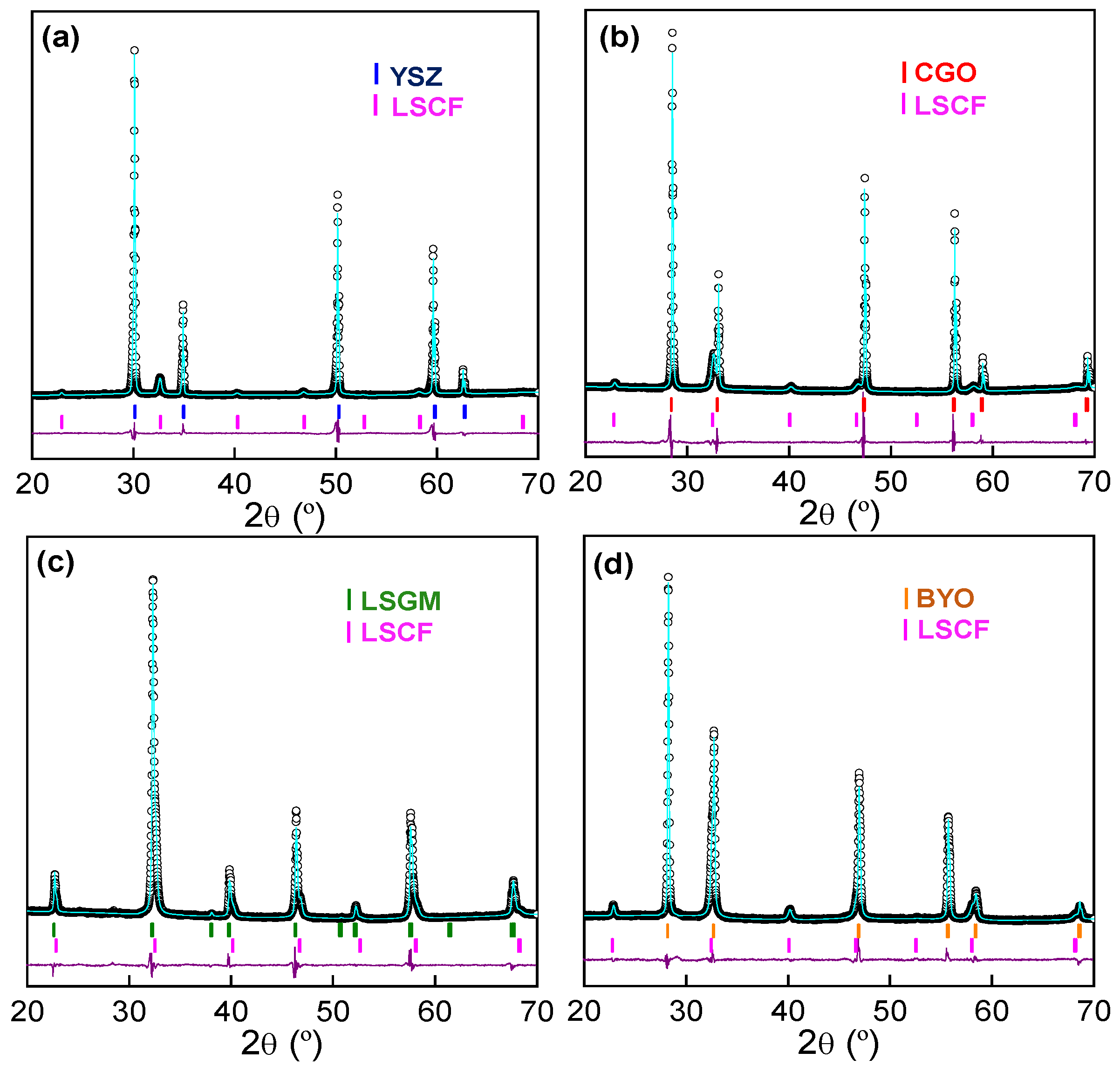
3.1. Phase Formation
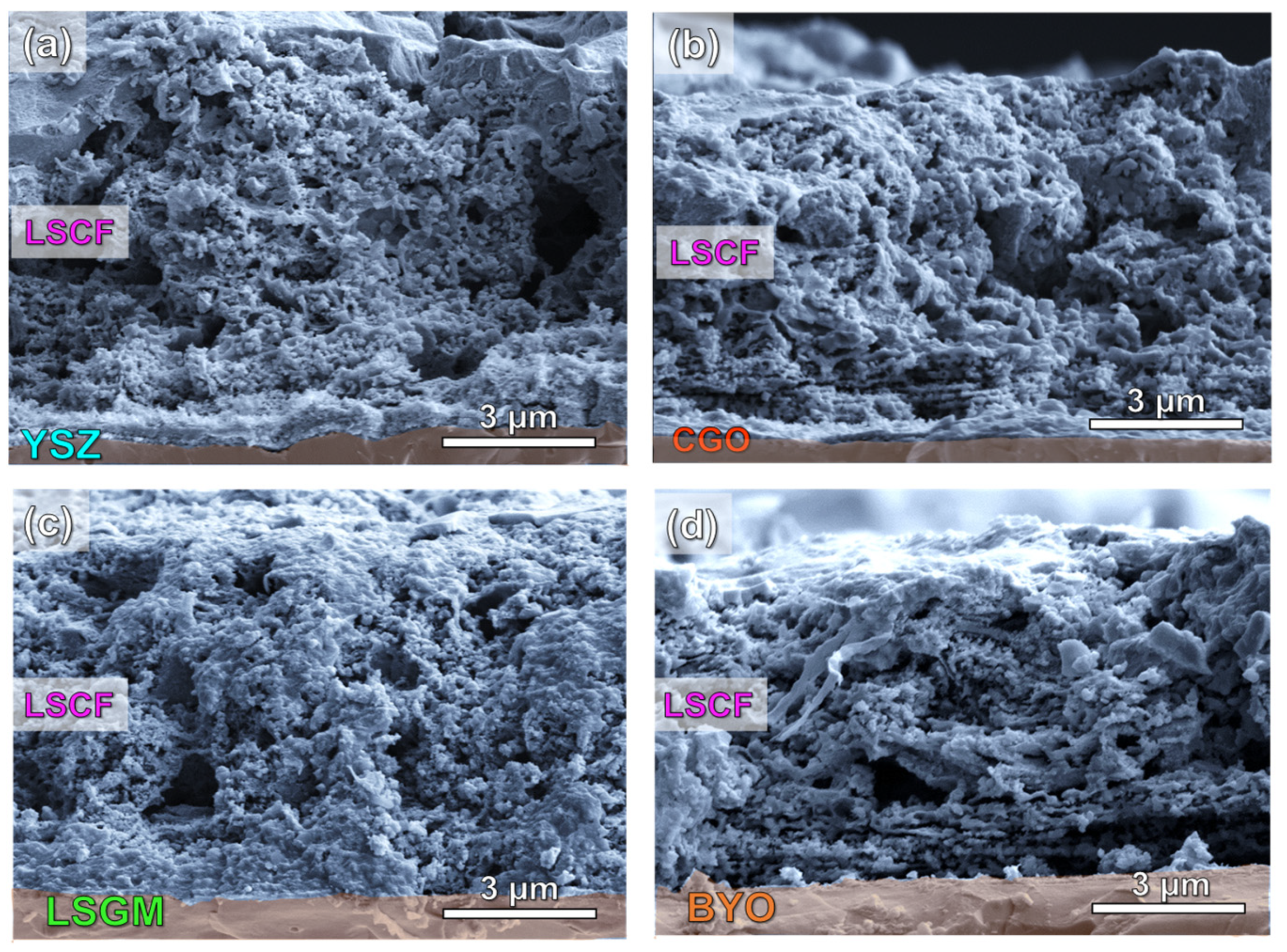
The XRD patterns of the LSCF cathode, deposited by spray-pyrolysis at 250 °C onto different electrolytes and calcined at 700 °C for 1 h, are displayed in Figure 1. The XRD patterns were adequately refined by the Rietveld method in the P m 3 ¯ m space groups for LSCF, P b n m for LSGM and F m 3 ¯ m for YSZ, CGO and BYO, obtaining a good fitting of the experimental data with low disagreement factors (Rwp = 5–6%) (Table 2). Moreover, additional diffraction peaks associated with secondary phases are not observed due to the rapid fabrication and low temperature used in the present work. This avoids the formation of undesired reaction products, such as SrZrO3 and La2Zr2O7, at the LSCF/YSZ interface [28,41].
It has to also be mentioned that LSCF and LSGM phases are not easily discernible in the pattern because their diffraction peaks appear overlapped, since the crystal structure and cell parameters are similar (Figure 1c). It is also worth noting that bulk LSCF usually crystallizes with a rhombohedral symmetry (s.g. R 3 ¯ c ). However, a cubic polymorph is stabilized at room temperature due to the different oxygen non-stoichiometry and surface free energy of a nanostructured LSCF cathode. A similar behavior was previously observed for related compositions, such as La0.6Sr0.4Co0.8Fe0.2O3-δ and La0.6Sr0.4CoO3-δ [42,43].
Regarding the cell parameters of LSCF, these remain practically unaltered, regardless of the electrolyte used, ranging between 3.8820(4) and 3.8883(4) Å (Table 2). This finding further confirms that compounds with the same crystal structure and cation composition are obtained. The average crystallite size of LSCF, calculated by the Scherrer’s equation, is also independent of the electrolyte, varying between 21 and 24 nm (Table 2).

3.2. Microstructure

SEM images of the LSCF layers deposited onto different electrolytes with a thickness of approximately 1 mm are shown in Figure 2. The electrode layers have a similar thickness of 8 ± 1 µm and exhibit good adhesion to the substrates without delamination or cracks despite the low sintering temperature used (700 °C). A porous microstructure is achieved due to incomplete decomposition of the precursors during the deposition process at 250 °C, which are removed during the post-thermal treatment at 700 °C, creating additional porosity [42]. It should also be noted that no substantial differences are observed between the electrode morphologies regardless of the electrolyte used (Figure 2a–d). In all cases, the nanostructured electrodes show a laminated morphology, which is significantly different to that observed for traditional screen-printed LSCF electrodes sintered between 1000 and 1200 °C [22,30].
Lowering the deposition temperature has additional benefits for the electrode performance because the cation interdiffusion between the cell layers is minimized, preventing the chemical reactivity at the electrode/electrolyte interface [44]. In a previous work, LSCF cathode was directly deposited by spray-pyrolysis on YSZ electrolyte and negligible degradation was observed at low temperature after long-term operation [28].
Moreover, the thermal strain gradients caused by the mismatch between the thermal expansion behavior of the LSCF electrode (14.8·10−6 K−1) and the electrolytes (10.3, 12.1, 11.5 and ~13.6·10−6 K−1 for YSZ, CGO, LSGM and BYO, respectively) may cause delamination or cracks, negatively affecting the performance of conventional electrodes prepared at high sintering temperatures [45,46,47]. However, this drawback is reduced in nanostructured electrodes with a large number of grain boundary interfaces [11].

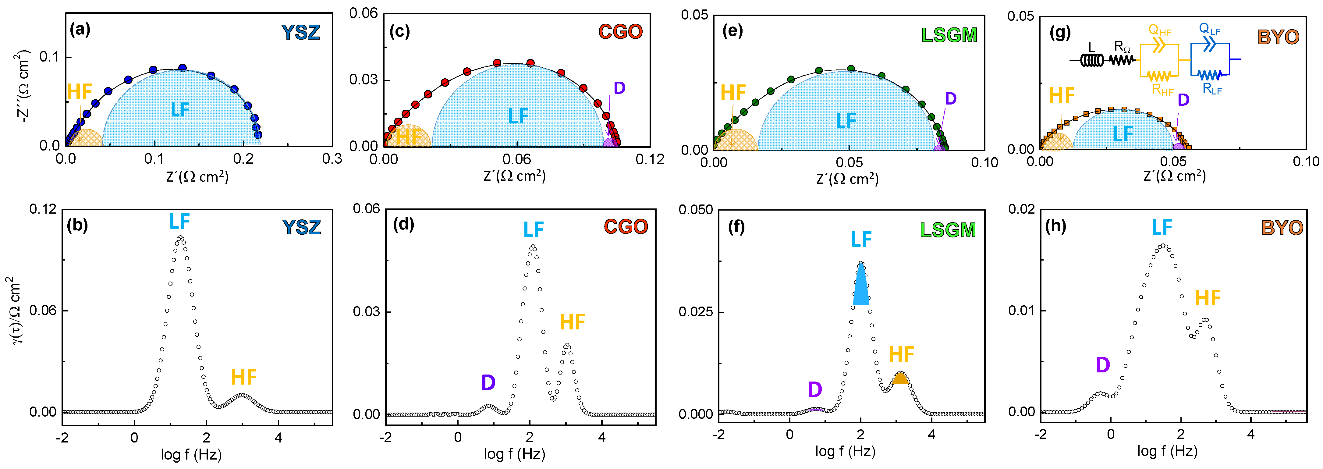
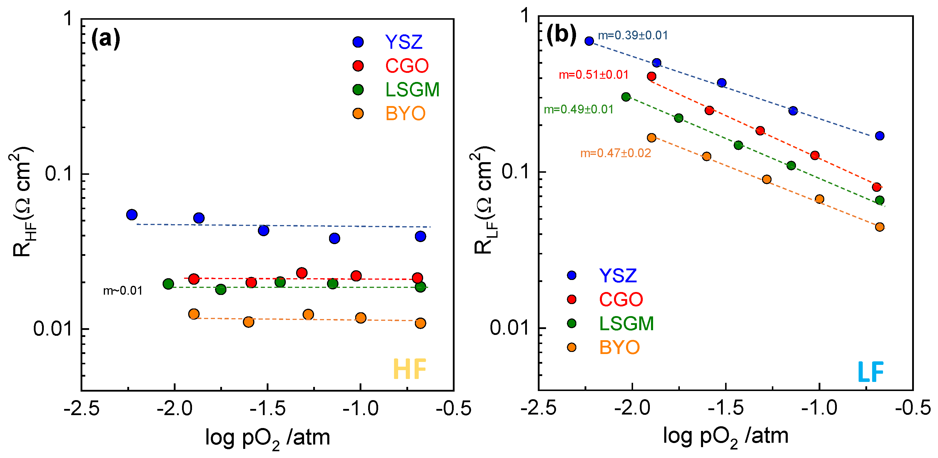
3.3. Electrochemical Characterization

The electrical characterization was carried out by impedance spectroscopy in symmetrical cells at open circuit voltage using Pt as current collector.
The impedance spectra show similar features for all the electrolytes, where the asymmetric arc suggests the presence of different contributions to the overall polarization resistance (Figure 3). The impedance spectra were firstly analyzed by distribution of relaxation times (DRT) to distinguish the different processes involved in the ORR (Figure 3). Two main contributions are observed in the DRT spectra regardless the electrolyte composition. The high frequency contribution (HF), centered at ~103 Hz, is usually attributed to charge transfer processes at the electrode/electrolyte interface [48,49], while the low frequency process (LF), located between 10 and 100 Hz, is assigned to charge transfer or oxygen dissociation processes occurring on the electrode surface [50,51]. The latter process is the main resistive contribution to the overall polarization resistance. A minor contribution is also detected at a very low frequency of ~1 Hz, labelled as D, which is related to gas-phase diffusion limitations into the electrode [48,49]. Similar findings have previously been observed by DRT analysis for commercial, nanostructured, and nanofiber LSCF electrodes [52].
Based on the DRT analysis, the impedance spectra were fitted using the equivalent circuit of the inset of Figure 3g, where L is an inductor attributed to the electrochemical setup and R represents the electrolyte resistance. Each specific electrode process was fitted by considering an RQ element, where R is a resistance in parallel with a constant phase element Q. Since the diffusion process D is rather low, it was not considered during the fitting.
For a better understanding of the influence of the electrolyte on the ORR properties, each electrode contribution was studied separately as a function of temperature (Figure 4). It is found that the resistance of the high (RHF) and low frequency (RLF) contributions are affected by the composition of the electrolyte. In particular, RHF decreases as the ionic conductivity of the electrolyte increases, YSZ > CGO ≥ LSGM > BYO, attributed to a faster oxide ion transfer at the electrode/electrolyte interface. This is further confirmed by the lower activation energy of BYO (1.08 eV) compared to CGO (1.14 eV), LSGM (1.25 eV) and YSZ (1.33 eV) (inset Figure 4a). Similarly, RLF is strongly affected by the ionic conductivity of the electrolyte, indicating that the electrolyte not only improves the oxide-ion transfer at the interface, but also extends the surface paths for the electrochemical reaction [53]. Similar findings were observed for different active layers incorporated between the cathode and the electrolyte [14,53,54]. As expected, the corresponding activation energy values for RLF are higher than those for RHF, ranging from 1.35 eV for BYO to 1.61 eV for YSZ (inset Figure 4b).
In contrast, the capacitances of the high (CHF) and low (CLF) frequency contributions are nearly independent of the measuring temperature and the electrolyte (Figure 4c,d). It is well reported that the electrode capacitance increases for those electrodes with high TPB length [55]. For this reason, the LSCF nanostructured electrodes exhibit high capacitance values of ~6·10−3 and 2·10−2 F cm−2 for the HF and LF contributions, respectively.
Figure 5 shows the overall polarization resistance (Rp = RHF + RLF) as function of the temperature for LSCF deposited onto the different electrolytes. In the whole temperature range, Rp decreases as the ionic conductivity of the electrolyte increases in the following order: YSZ > CGO > LSGM > BYO. The LSCF deposited onto BYO shows an Rp value of only 0.058 Ω cm2 at 700 °C, which is one of the lowest values reported in the literature for pure La0.6Sr0.4Co0.2Fe0.8O3-δ (Table 1). Similarly, the activation energy of Rp decreases from 1.48 eV for YSZ to 1.39 eV for BYO, which confirms that an increase of the ionic conductivity of the electrolyte induces faster ORR kinetics.
In order to get further insight into the rate-limiting steps involved in the ORR, the impedance spectra were collected as a function of the oxygen partial pressure (pO2). The relationship between the electrode polarization resistance of each process and the oxygen partial pressure can be expressed as R = Ro(pO2)m, where the parameter m provides information about the nature of the electrode processes. Despite the fact that the complete ORR can be summarized as follows, O 2 + 2 V ö + 4 e   2 O o x , this reaction comprises multiple sub-steps with different m values that are displayed in Figure 6a: (1) the oxygen adsorption on the electrode surface (m = 1, O 2 , g a s O 2 ,   a d s ); (2) the oxygen gas dissociation on the electrode surface (m = 1/2, O2,ads → 2Oads); (3) one electron oxygen reduction (m = 3/8, O a d + e O a d ) and (4) (m = 1/8, O a d + e O a d ) or (5) complete reduction of the oxygen atoms (m = 1/4, O a d + 2 e + V ö O o x ); and (6) the oxygen ion incorporation at the electrode/electrolyte interface (m = 0, O o , electrode x O o , eletrolyte x ) [56]. It has to be noted that all these steps are not detectable for a specific electrode. Only the rate-limiting steps are discernible in the impedance spectra. In this context, different rate-limiting steps have been proposed in the literature for pure LSCF, obtained from different preparation routes and deposited onto different electrolytes (see Table 1), which difficulties the possibility to stablish a clear relationship between the electrolyte used and the rate-limiting steps involved in the ORR. It its worth mentioning that this is a critical factor to design an adequate electrode microstructure and to improve the cell performance and durability.
Figure 6b,c show representative impedance spectra at 700 °C and different oxygen partial pressures for LSCF deposited onto YSZ and CGO electrolytes, respectively. Since the closeness of the characteristic frequencies of each sub-reaction hinders the identification of the different electrode processes, DRT analysis of the impedance data was performed (Figure 6d,e). The DRT analysis confirms the presence of two main electrode contributions for all samples in the whole pO2 range studied. As expected, the higher the pO2 the lower overall electrode polarization resistance. RHF and RLF contributions were determined by the integral area under each peak and represented in Figure 7a,b, respectively. The HF process is nearly independent of the oxygen partial pressure for all samples (m ~ 0), confirming that this process is related to the oxide ion transport across the electrode/electrolyte interface. On the other hand, the LF process shows a m ~ 0.5 for CGO, LSGM, and BYO electrolytes, which is attributed to oxygen dissociation at the electrode surface [27]. However, a different rate-limiting-step is observed for LSCF deposited on YSZ. In this case, the m ~ 3/8 indicates that this process is possibly assigned to oxygen dissociative adsorption followed by charge transfer [55,57]. The poorer oxide ion conductivity of YSZ at intermediate temperatures, in comparison to CGO, LSGM, and BYO, could explain the different behavior. In fact, the ionic conduction in YSZ cell is limited at the electrode/electrolyte interface, inducing a slower charge transfer at the electrode surface. In the literature, different ORR processes were found, due to the different synthetic methods and sintering temperatures employed, which highly affect the electrode microstructure and thus the electrochemical properties (Table 1). For instance, Wang et al. [26] found two rate-limiting steps for screen-printed LSCF on Sm-doped CeO2 electrolyte with m = 0.24 and 0.44. Marinha et al. [21] observed three processes for spray-pyrolysis LSCF electrodes on CGO with m = 0, 0.28 and 0.71 whiles Kim et al. [23] observed only two processes with m = 0 and 0.28 (Table 1). Moreover, in contrast to previous works [45,47], gas diffusion limitations (m = 1) are not observed for the spray-pyrolysis electrodes (Table 1). Hence, the nanostructured LSCF electrodes, deposited by spray-pyrolysis at low temperature, have an adequate porosity, avoiding problems related to gas diffusion.

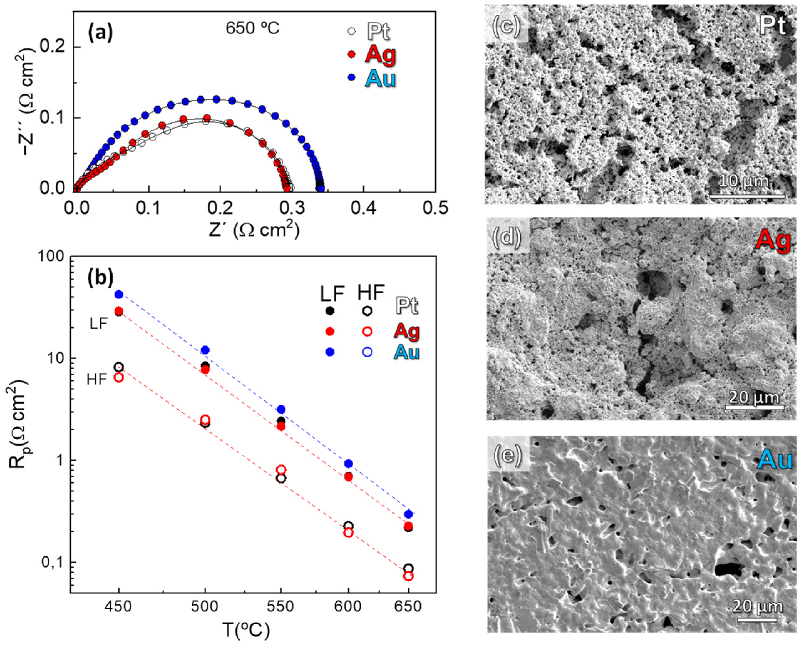
3.4. Influence on the Current Collector Layer

Finally, we have studied the effect of the current collector material on the electrochemical properties of the LSCF nanostructured electrode deposited onto a CGO electrolyte. It is well known that an adequate current collector is needed to ensure a uniform electric field and proper efficiency of the cell. Some current collectors, such as Pt, can be electrochemically active for ORR, or even react with the electrode [58]. For these reasons, Ag and Au pastes are also investigated as current collectors in a symmetrical cell configuration. Figure 8a compares the impedance spectra of LSCF/CGO/LSCF cells with different current collectors, where almost identical Rp values are observed for the Pt- and Ag-containing cells (~0.29 Ω cm2 at 650 °C). However, the Au-containing cell shows slightly higher values (0.34 Ω cm2).
A deeper analysis of the different electrode contributions to the overall polarization resistance reveals that the HF processes, attributed to the oxide ion transfer at the electrode/electrolyte interface, are similar for all samples (Figure 8b). Thus, the main differences between the cells are related to changes in the LF response. In particular, the cell with Au current collector shows the highest RLF values. SEM images of the current collector surface reveal a good porosity for both Pt and Ag cells. In contrast, a dense layer with low superficial porosity is observed for the Au current collector, which partially blocks the active sites on the electrode surface and, as consequence, the RLF contribution increases (Figure 8c–e). A similar behavior was observed for La0.8Sr0.2FeO3-δ electrode with Au current collector when compared to Pt and Ag [59].

4. Conclusions

Nanostructured La0.6Sr0.4Co0.2Fe0.8O3-δ (LSCF) electrodes were prepared by spray-pyrolysis deposition onto different electrolytes: Zr0.84Y0.16O1.92 (YSZ), Ce0.9Gd0.1O1.95 (CGO), La0.9Sr0.1Ga0.8Mg0.2O2.85 (LSGM), and Bi1.5Y0.5O3-δ (BYO). The electrochemical measurements revealed a direct relationship between the ionic conductivity of the electrolyte and the polarization resistance of the cells, which was improved by a faster oxide ion transport at the electrode/electrolyte interface and an extension of the surface paths for the electrochemical reactions. The polarization resistance of LSCF deposited onto BYO was 3.5 times lower than that observed for YSZ, i.e., 0.058 and 0.21 Ω cm2 at 700 °C, respectively, which was attributed to the poorer ionic conductivity of YSZ at intermediate temperatures. The analysis of the impedance spectra by distribution of relaxation times and equivalent circuit models revealed that similar rate-limiting steps are involved in the ORR for CGO, LSGM, and BYO electrolytes, which were assigned to oxygen gas dissociation on the electrode surface and oxide ion incorporation at the electrode/electrolyte interface. An additional study regarding the influence of the current collector layer revealed that both Pt and Ag are suitable materials to obtain representative polarization resistance values, while Au partially blocks the active sites for oxygen reduction on the electrode surface. All these results demonstrate that the ionic conductivity at the electrode/electrolyte interface is a bottleneck for the electrode performance of LSCF, results that can be extended to other electrodes for SOFCs.

Author Contributions

Conceptualization, J.Z.-G. and D.M.-L.; methodology, J.Z.-G.; software, L.C.-J.; investigation, J.Z.-G. and L.C.-J.; resources, E.R.L.; data curation, L.C.-J. and J.M.P.-V.; writing—original draft preparation, J.Z.-G.; writing—review and editing, L.C.-J., J.M.P.-V., E.R.L. and D.M.-L.; supervision, J.M.P.-V., E.R.L. and D.M.-L.; project administration, D.M.-L.; funding acquisition, D.M.-L. All authors have read and agreed to the published version of the manuscript.

Funding

This work was funded by PID2021-126009OB-I00 and PID2019-110249RB-I00 (Ministerio de Ciencia, Innovación y Universidades) and UMA18-FEDERJA-033 (Junta de Andalucia, Spain/FEDER). J.Z.G. thanks the Ministerio de Ciencia, Innovación y Universidades for his FPU grant (FPU17/02621). L.C.J. would like to thank Plan Andaluz de Investigación, Desarrollo e Innovación (PAIDI 2020) for the research support (DOC 01168).

Data Availability Statement

The data presented in this study are available on request from the corresponding author.

Conflicts of Interest

The authors declare no conflict of interest.

References

  1. Gür, T.M. Review of Electrical Energy Storage Technologies, Materials and Systems: Challenges and Prospects for Large-Scale Grid Storage. Energy Environ. Sci. 2018, 11, 2696–2767. [Google Scholar] [CrossRef]
  2. Gao, Z.; Mogni, L.V.; Miller, E.C.; Railsback, J.G.; Barnett, S.A. A Perspective on Low-Temperature Solid Oxide Fuel Cells. Energy Environ. Sci. 2016, 9, 1602–1644. [Google Scholar] [CrossRef]
  3. Boldrin, P.; Brandon, N.P. Progress and Outlook for Solid Oxide Fuel Cells for Transportation Applications. Nat. Catal. 2019, 2, 571–577. [Google Scholar] [CrossRef] [Green Version]
  4. Vinoth Kumar, R.; Khandale, A.P. A Review on Recent Progress and Selection of Cobalt-Based Cathode Materials for Low Temperature-Solid Oxide Fuel Cells. Renew. Sustain. Energy Rev. 2022, 156, 111985. [Google Scholar] [CrossRef]
  5. Lima, A.J.M.; Silva, V.D.; Raimundo, R.A.; Morales, M.A.; Simões, T.A.; Loureiro, F.J.A.; Fagg, D.P.; Macedo, D.A.; Nascimento, R.M. Fe-Doped Calcium Cobaltites as Electrocatalysts for Oxygen Evolution Reaction. Ceram. Int. 2021, 47, 26109–26118. [Google Scholar] [CrossRef]
  6. Yoo, S.; Shin, J.Y.; Kim, G. Thermodynamic and Electrical Characteristics of NdBaCo2O5+δ at Various Oxidation and Reduction States. J. Mater. Chem. 2011, 21, 439–443. [Google Scholar] [CrossRef]
  7. Švarcová, S.; Wiik, K.; Tolchard, J.; Bouwmeester, H.J.M.; Grande, T. Structural Instability of Cubic Perovskite BaxSr1- xCo1-yFeyO3-δ. Solid State Ionics 2008, 178, 1787–1791. [Google Scholar] [CrossRef]
  8. Jin, F.; Liu, J.; Shen, Y.; He, T. Improved Electrochemical Performance and Thermal Expansion Compatibility of LnBaCoFeO5+δ-Sm0.2Ce0.8O1.9 (Ln=Pr and Nd) Composite Cathodes for IT-SOFCs. J. Alloys Compd. 2016, 685, 483–491. [Google Scholar] [CrossRef]
  9. Jiang, S.P. A Comparison of O2 Reduction Reactions on Porous (La,Sr)MnO3 and (La,Sr)(Co,Fe)O3 Electrodes. Solid State Ionics 2002, 146, 1–22. [Google Scholar] [CrossRef]
  10. Kaur, P.; Singh, K. Review of Perovskite-Structure Related Cathode Materials for Solid Oxide Fuel Cells. Ceram. Int. 2020, 46, 5521–5535. [Google Scholar] [CrossRef]
  11. dos Santos-Gómez, L.; Zamudio-García, J.; Porras-Vázquez, J.M.; Losilla, E.R.; Marrero-López, D. Recent Progress in Nanostructured Electrodes for Solid Oxide Fuel Cells Deposited by Spray Pyrolysis. J. Power Sources 2021, 507. [Google Scholar] [CrossRef]
  12. Jiang, S.P. Development of Lanthanum Strontium Cobalt Ferrite Perovskite Electrodes of Solid Oxide Fuel Cells—A Review. Int. J. Hydrogen Energy 2019, 44, 7448–7493. [Google Scholar] [CrossRef]
  13. Plonczak, P.; Søgaard, M.; Bieberle-Hütter, A.; Hendriksen, P.V.; Gauckler, L.J. Electrochemical Characterization of La0.58Sr0.4Co0.2Fe0.8O3−δ Thin Film Electrodes Prepared by Pulsed Laser Deposition. J. Electrochem. Soc. 2012, 159, B471–B482. [Google Scholar] [CrossRef]
  14. Zamudio-García, J.; Caizán-Juanarena, L.; Porras-Vázquez, J.M.; Losilla, E.R.; Marrero-lópez, D. Boosting the Performance of La0.8Sr0.2MnO3-δ Electrodes by The Incorporation of Nanocomposite Active Layers. Adv. Mater. Interfaces 2022, 9, 2200702. [Google Scholar] [CrossRef]
  15. Nicollet, C.; Flura, A.; Vibhu, V.; Rougier, A.; Bassat, J.M.; Grenier, J.C. An Innovative Efficient Oxygen Electrode for SOFC: Pr6O11 Infiltrated into Gd-Doped Ceria Backbone. Int. J. Hydrogen Energy 2016, 41, 15538–15544. [Google Scholar] [CrossRef]
  16. Dos Santos-Gómez, L.; Losilla, E.R.; Martín, F.; Ramos-Barrado, J.R.; Marrero-López, D. Novel Microstructural Strategies to Enhance the Electrochemical Performance of La0.8Sr0.2MnO3-δ Cathodes. ACS Appl. Mater. Interfaces 2015, 7, 7197–7205. [Google Scholar] [CrossRef] [Green Version]
  17. Nicollet, C.; Flura, A.; Vibhu, V.; Rougier, A.; Bassat, J.-M.; Grenier, J.-C. Lanthanum Nickelate Infiltration into Porous Gd-Doped Ceria As Cathode for Solid Oxide Fuel Cells. ECS Trans. 2015, 68, 837–845. [Google Scholar] [CrossRef]
  18. Beckel, D.; Muecke, U.P.; Gyger, T.; Florey, G.; Infortuna, A.; Gauckler, L.J. Electrochemical Performance of LSCF Based Thin Film Cathodes Prepared by Spray Pyrolysis. Solid State Ionics 2007, 178, 407–415. [Google Scholar] [CrossRef]
  19. Haider, M.A.; McIntosh, S. The Influence of Grain Size on La0.6Sr0.4Co0.2Fe0.8O3-δ Thin Film Electrode Impedance. J. Electrochem. Soc. 2011, 158, B1128. [Google Scholar] [CrossRef]
  20. dos Santos-Gómez, L.; Porras-Vázquez, J.M.; Losilla, E.R.; Martín, F.; Ramos-Barrado, J.R.; Marrero-López, D. Stability and Performance of La0.6Sr0.4Co0.2Fe0.8O3-δ Nanostructured Cathodes with Ce0.8Gd0.2O1.9 Surface Coating. J. Power Sources 2017, 347, 178–185. [Google Scholar] [CrossRef]
  21. Marinha, D.; Dessemond, L.; Djurado, E. Electrochemical Investigation of Oxygen Reduction Reaction on La0.6Sr0.4Co0.2Fe0.8O3-δ Cathodes Deposited by Electrostatic Spray Deposition. J. Power Sources 2012, 197, 80–87. [Google Scholar] [CrossRef]
  22. Lu, M.Y.; Railsback, J.G.; Wang, H.; Liu, Q.; Chart, Y.A.; Zhang, S.L.; Barnett, S.A. Stable High Current Density Operation of La0.6Sr0.4Co0.2Fe0.8O3-δ: Oxygen Electrodes. J. Mater. Chem. A 2019, 7, 13531–13539. [Google Scholar] [CrossRef]
  23. Kim, Y.-M.; Pyun, S.-I.; Kim, J.-S.; Lee, G.-J. Mixed Diffusion and Charge-Transfer-Controlled Oxygen Reduction on Dense LaSrxCo0.2Fe0.8O3−δ Electrodes with Various Sr Contents. J. Electrochem. Soc. 2007, 154, B802. [Google Scholar] [CrossRef]
  24. Lee, J.W.; Liu, Z.; Yang, L.; Abernathy, H.; Choi, S.H.; Kim, H.E.; Liu, M. Preparation of Dense and Uniform La0.6Sr0.4Co0.2Fe0.8O3-δ (LSCF) Films for Fundamental Studies of SOFC Cathodes. J. Power Sources 2009, 190, 307–310. [Google Scholar] [CrossRef]
  25. Zhou, F.; Liu, Y.; Zhao, X.; Tang, W.; Yang, S.; Zhong, S.; Wei, M. Effects of Cerium Doping on the Performance of LSCF Cathodes for Intermediate Temperature Solid Oxide Fuel Cells. Int. J. Hydrogen Energy 2018, 43, 18946–18954. [Google Scholar] [CrossRef]
  26. Wang, Z.; Sun, H.; Li, J.; Guo, X.; Hu, Q.; Yang, Z.; Yu, F.; Li, G. Modified La0.6Sr0.4Co0.2Fe0.8O3-δ Cathodes with the Infiltration of Er0.4Bi1.6O3 for Intermediate-Temperature Solid Oxide Fuel Cells. Int. J. Hydrogen Energy 2021, 46, 22932–22941. [Google Scholar] [CrossRef]
  27. Yoo, C.Y.; Yun, D.S.; Park, S.Y.; Park, J.; Joo, J.H.; Park, H.; Kwak, M.; Yu, J.H. Investigation of Electrochemical Properties of Model Lanthanum Strontium Cobalt Ferrite-Based Cathodes for Proton Ceramic Fuel Cells. Electrocatalysis 2016, 7, 280–286. [Google Scholar] [CrossRef]
  28. dos Santos-Gómez, L.; Hurtado, J.; Porras-Vázquez, J.M.; Losilla, E.R.; Marrero-López, D. Durability and Performance of CGO Barriers and LSCF Cathode Deposited by Spray-Pyrolysis. J. Eur. Ceram. Soc. 2018, 38, 3518–3526. [Google Scholar] [CrossRef]
  29. Angoua, B.F.; Slamovich, E.B. Single Solution Spray Pyrolysis of La0.6Sr0.4Co0.2Fe0.8O3-δ-Ce0.8Gd0.2O1.9 (LSCF-CGO) Thin Film Cathodes. Solid State Ionics 2012, 212, 10–17. [Google Scholar] [CrossRef]
  30. Bebelis, S.; Kotsionopoulos, N.; Mai, A.; Tietz, F. Electrochemical Characterization of Perovskite-Based SOFC Cathodes. J. Appl. Electrochem. 2006, 37, 15–20. [Google Scholar] [CrossRef]
  31. Perry Murray, E.; Sever, M.J.; Barnett, S.A. Electrochemical Performance of (La,Sr)(Co,Fe)O3–(Ce, Gd)O3 Composite Cathodes. Solid State Ionics 2002, 148, 27–34. [Google Scholar] [CrossRef]
  32. Nie, L.; Liu, M.; Zhang, Y.; Liu, M. La0.6Sr0.4Co0.2Fe0.8O3-δ Cathodes Infiltrated with Samarium-Doped Cerium Oxide for Solid Oxide Fuel Cells. J. Power Sources 2010, 195, 4704–4708. [Google Scholar] [CrossRef]
  33. Kournoutis, V.C.; Tietz, F.; Bebelis, S. AC Impedance Characterisation of a La0.8Sr0.2Co0.2Fe0.8O3-δ Electrode. Fuel Cells 2009, 9, 852–860. [Google Scholar] [CrossRef]
  34. Zhang, Q.; Hou, Y.; Chen, L.; Wang, L.; Chou, K. Enhancement of Electrochemical Performance for Proton Conductive Solid Oxide Fuel Cell by 30%GDC-LSCF Cathode. Ceram. Int. 2022, 48, 17816–17827. [Google Scholar] [CrossRef]
  35. Philippeau, B.; Mauvy, F.; Nicollet, C.; Fourcade, S.; Grenier, J.C. Oxygen Reduction Reaction in Pr2NiO4+δ/Ce0.9Gd0.1O1.95 and La0.6Sr0.4Co0.2Fe0.8O3−δ/La0.8Sr0.2Ga0.8Mg0.2O2.80 half cells: An electrochemical study. J. Solid State Electrochem. 2015, 19, 871–882. [Google Scholar] [CrossRef]
  36. X’Pert HighScore Plus Software, v3.0e; PANalytical B. V.: Amelo, The Netherlands, 2012.
  37. Larson, A.C.; Von Dreele, R.B. General Structure Analysis System (GSAS) Software; Rep. No. LAUR-86-748; LosAlamos National Lab: California, CA, USA, 2004.
  38. Dos Santos-Gómez, L.; Porras-Vázquez, J.M.; Losilla, E.R.; Marrero-López, D. Improving the Efficiency of Layered Perovskite Cathodes by Microstructural Optimization. J. Mater. Chem. A 2017, 5, 7896–7904. [Google Scholar] [CrossRef]
  39. Johnson, D. ZView, A Software Program for IES Analysis, Version 2.8; Scribner Assoc. Inc.: Southern Pines, NC, USA, 2002.
  40. Wan, T.H.; Saccoccio, M.; Chen, C.; Ciucci, F. Influence of the Discretization Methods on the Distribution of Relaxation Times Deconvolution: Implementing Radial Basis Functions with DRTtools. Electrochim. Acta 2015, 184, 483–499. [Google Scholar] [CrossRef]
  41. Lim, Y.; Park, J.; Lee, H.; Ku, M.; Kim, Y.B. Rapid Fabrication of Lanthanum Strontium Cobalt Ferrite (LSCF) with Suppression of LSCF/YSZ Chemical Side Reaction via Flash Light Sintering for SOFCs. Nano Energy 2021, 90, 106524. [Google Scholar] [CrossRef]
  42. Marrero-López, D.; Romero, R.; Martín, F.; Ramos-Barrado, J.R. Effect of the Deposition Temperature on the Electrochemical Properties of La0.6Sr0.4Co0.8Fe0.2O3-δ Cathode Prepared by Conventional Spray-Pyrolysis. J. Power Sources 2014, 255, 308–317. [Google Scholar] [CrossRef]
  43. Acuña, L.M.; Peña-Martínez, J.; Marrero-López, D.; Fuentes, R.O.; Nuñez, P.; Lamas, D.G. Electrochemical Performance of Nanostructured La0.6Sr0.4CoO3-δ and Sm0.5Sr0.5CoO3-δ Cathodes for IT-SOFCs. J. Power Sources 2011, 196, 9276–9283. [Google Scholar] [CrossRef]
  44. Zhang, L.; Chen, G.; Dai, R.; Lv, X.; Yang, D.; Geng, S. A Review of the Chemical Compatibility between Oxide Electrodes and Electrolytes in Solid Oxide Fuel Cells. J. Power Sources 2021, 492. [Google Scholar] [CrossRef]
  45. Nikonov, A.V.; Kuterbekov, K.A.; Bekmyrza, K.Z.; Pavzderin, N.B. A Brief Review of Conductivity and Thermal Expansion of Perovskite-Related Oxides for SOFC Cathode. Eurasian J. Phys. Funct. Mater. 2018, 2, 274–292. [Google Scholar] [CrossRef] [Green Version]
  46. Zarabi Golkhatmi, S.; Asghar, M.I.; Lund, P.D. A Review on Solid Oxide Fuel Cell Durability: Latest Progress, Mechanisms, and Study Tools. Renew. Sustain. Energy Rev. 2022, 161, 112339. [Google Scholar] [CrossRef]
  47. Datta, P.; Majewski, P.; Aldinger, F. Thermal Expansion Behaviour of Sr- and Mg-Doped LaGaO3 Solid Electrolyte. J. Eur. Ceram. Soc. 2009, 29, 1463–1468. [Google Scholar] [CrossRef]
  48. Osinkin, D.A. An Approach to the Analysis of the Impedance Spectra of Solid Oxide Fuel Cell Using the DRT Technique. Electrochim. Acta 2021, 372, 137858. [Google Scholar] [CrossRef]
  49. Xia, J.; Wang, C.; Wang, X.; Bi, L.; Zhang, Y. A Perspective on DRT Applications for the Analysis of Solid Oxide Cell Electrodes. Electrochim. Acta 2020, 349, 136328. [Google Scholar] [CrossRef]
  50. Osinkin, D.A. Detailed Analysis of Electrochemical Behavior of High–Performance Solid Oxide Fuel Cell Using DRT Technique. J. Power Sources 2022, 527. [Google Scholar] [CrossRef]
  51. Hong, J.; Bhardwaj, A.; Bae, H.; Kim, I.; Song, S.-J. Electrochemical Impedance Analysis of SOFC with Transmission Line Model Using Distribution of Relaxation Times (DRT). J. Electrochem. Soc. 2020, 167, 114504. [Google Scholar] [CrossRef]
  52. Chen, Y.; Bu, Y.; Zhang, Y.; Yan, R.; Ding, D.; Zhao, B.; Yoo, S.; Dang, D.; Hu, R.; Yang, C.; et al. A Highly Efficient and Robust Nanofiber Cathode for Solid Oxide Fuel Cells. Adv. Energy Mater. 2017, 7, 1–7. [Google Scholar] [CrossRef]
  53. Zapata-Ramírez, V.; Dos Santos-Gómez, L.; Mather, G.C.; Marrero-López, D.; Pérez-Coll, D. Enhanced Intermediate-Temperature Electrochemical Performance of Air Electrodes for Solid Oxide Cells with Spray-Pyrolyzed Active Layers. ACS Appl. Mater. Interfaces 2020, 12, 10571–10578. [Google Scholar] [CrossRef]
  54. Araújo, A.J.M.; Loureiro, F.J.A.; Holz, L.I.V.; Graça, V.C.D.; Grilo, J.P.F.; Macedo, D.A.; Paskocimas, C.A.; Fagg, D.P. Creating New Surface-Exchange Pathways on the Misfit Ca-Cobaltite Electrode by the Addition of an Active Interlayer. J. Power Sources 2021, 510. [Google Scholar] [CrossRef]
  55. Dos Santos-Gómez, L.; Zamudio-García, J.; Porras-Vázquez, J.M.; Losilla, E.R.; Marrero-López, D. Nanostructured BaCo0.4Fe0.4Zr0.1Y0.1O3-δ Cathodes with Different Microstructural Architectures. Nanomaterials 2020, 10, 1055. [Google Scholar] [CrossRef] [PubMed]
  56. Jiang, Z.; Lei, Z.; Ding, B.; Xia, C.; Zhao, F.; Chen, F. Electrochemical Characteristics of Solid Oxide Fuel Cell Cathodes Prepared by Infiltrating (La,Sr)MnO3 Nanoparticles into Yttria-Stabilized Bismuth Oxide Backbones. Int. J. Hydrogen Energy 2010, 35, 8322–8330. [Google Scholar] [CrossRef]
  57. Peng, R.; Wu, T.; Liu, W.; Liu, X.; Meng, G. Cathode Processes and Materials for Solid Oxide Fuel Cells with Proton Conductors as Electrolytes. J. Mater. Chem. 2010, 20, 6218–6225. [Google Scholar] [CrossRef]
  58. Wang, Y.; Wang, D.; Li, Y. A Fundamental Comprehension and Recent Progress in Advanced Pt-based ORR Nanocatalysts. SmartMat 2021, 2, 56–75. [Google Scholar] [CrossRef]
  59. Simner, S.P.; Electrochem, J.; Soc, A.; Simner, S.P.; Anderson, M.D.; Pederson, L.R.; Stevenson, J.W. Performance Variability of La(Sr)FeO3 SOFC Cathode with Pt, Ag, and Au Current Collectors. J. Electrochem. Soc. 2005, 152, A1851. [Google Scholar] [CrossRef]
Figure 1. Rietveld refinement of LSCF electrode deposited onto different electrolytes at 700 °C, (a) Zr0.84Y0.16O1.92 (YSZ), (b) Ce0.9Gd0.1O1.95 (CGO), (c) La0.9Sr0.1Ga0.8Mg0.2O2.85 (LSGM) and (d) Bi1.5Y0.5O3 (BYO).
Nanomaterials 12 03936 g001
Figure 2. SEM images of the LSCF deposited on different electrolytes at 700 °C, (a) YSZ, (b) CGO, (c) LSGM and (d) BYO.
Nanomaterials 12 03936 g002
Figure 3. Impedance spectra (top) and DRT analysis (bottom) at 700 °C of the LSCF electrode deposited on (a,b) YSZ, (c,d) CGO, (e,f) LSGM and (g,h) BYO. The inset of (g) shows the equivalent circuit used to fitting the data.
Nanomaterials 12 03936 g003
Figure 4. Temperature dependence of (a) RHF and (b) RLF resistance and (c) CHF and (d) CLF capacitance contributions of LSCF electrodes deposited on different electrolytes.
Nanomaterials 12 03936 g004
Figure 5. Overall polarization resistance of LSCF nanostructured electrodes deposited onto different electrolytes as a function of temperature. The inset figure compares the polarization resistance at 700 °C.
Nanomaterials 12 03936 g005
Figure 6. (a) Schematic diagram of the different sub-reactions of the oxygen reduction reaction. Impedance spectra at 700 °C of (b) LSCF/YSZ/LSCF and (c) LSCF/CGO/LSCF cells as a function of the oxygen partial pressure and the corresponding (d,e) DRT plots.
Nanomaterials 12 03936 g006
Figure 7. Polarization resistances of the (a) HF and (b) LF electrode contributions of LSCF with different electrolytes as a function of the oxygen partial pressure at 700 °C.
Nanomaterials 12 03936 g007
Figure 8. (a) Impedance spectra at 650 °C of LSCF electrodes deposited onto CGO electrolyte with Pt, Ag and Au as current collectors and (b) electrode resistance contributions as a function of the temperature. SEM images of the surface of (c) Pt, (d) Ag and (e) Au current collectors after the electrochemical tests.
Nanomaterials 12 03936 g008
Table 1. Brief summary of the polarization resistances (Rp) and reaction order (m) of the rate-limiting steps of the ORR of La0.6Sr0.4Fe0.8Co0.2O3-δ (LSCF) at 700 °C reported in the literature. The temperature is included when data is not available at 700 °C.
Fabrication TechniqueElectrolyteRp (Ω cm2)mRef.
Spray-pyrolysisZr0.84Y0.16O1.920.21~0
0.39
This work
Spray-pyrolysisCe0.9Gd0.1O1.950.11~0
0.51
This work
Spray-pyrolysisLa0.9Sr0.1Ga0.8Mg0.2O3-δ0.089~0
0.49
This work
Spray-pyrolysisBi1.5Y0.5O30.058~0
0.47
This work
Spray-pyrolysisCe0.8Gd0.2O1.90.7650 °C-[18]
Spray-pyrolysisCe0.8Gd0.2O1.90.9-[19]
Freeze-DryingCe0.8Gd0.2O1.90.3-[20]
Spray-pyrolysisCe0.8Gd0.2O1.910600 °C0
0.20
0.71
[21]
Screen-printingCe0.9Gd0.1O1.950.12-[22]
Solid-state reactionCe0.9Gd0.1O1.9515750 °C0
0.28
[23]
Magnetron sputteringCe0.9Gd0.1O1.95122-[24]
Screen-printingCe0.9Gd0.1O1.950.21750 ºC-[25]
Screen-printingSm0.2Ce0.8O1.90.55600 °C0.24
0.44
[26]
Co-precipitationBaZr0.8Y0.2O3-δ0.70600 °C0.16
0.50
[27]
Spray-pyrolysisZr0.84Y0.16O1.920.3650 °C-[28]
Spray-pyrolysisZr0.84Y0.16O1.923600 °C-[29]
Spray-dryingZr0.84Y0.16O1.922-[30]
Spin coatingZr0.84Y0.16O1.920.1750 °C-[31]
Pulsed laser depositionZr0.84Y0.16O1.929750 °C-[13]
Tape castingZr0.84Y0.16O1.920.4-[32]
Spray-dryingZr0.84Y0.16O1.925~0
0.25
[33]
Spray-dryingLa0.9Sr0.1Ga0.8Mg0.2O3-δ0.19-[34]
Screen-printingLa0.8Sr0.2Ga0.8Mg0.2O3-δ0.080.10
0.82
[35]
Table 2. Structural and microstructural parameters of LSCF cathode deposited onto different electrolytes by spray-pyrolysis.
ElectrolyteLattice Parameter (Å)Cell Volume (Å3)Rwp (%)dLSCF (nm)
YSZ3.8828 (4)58.540 (2)4.5724
CGO3.8876 (4)58.540 (2)4.8620
LSGM3.8820 (4)58.540 (2)4.01-
BYO3.8883 (4)58.540 (2)3.0122
Publisher’s Note: MDPI stays neutral with regard to jurisdictional claims in published maps and institutional affiliations.

