Communication

Anion-Exchange Blue Perovskite Quantum Dots for Efficient Light-Emitting Devices

1
Department of Electro-Optical Engineering, National Taipei University of Technology, Taipei 10608, Taiwan
2
Department of Mathematic and Physical Sciences, General Education, R.O.C. Air Force Academy, Kaohsiung 820009, Taiwan
3
Giant-Tek Corporation, Miaoli 35048, Taiwan
4
Department of Electronic Engineering, Ming Chi University of Technology, New Taipei 243303, Taiwan
*
Authors to whom correspondence should be addressed.
Nanomaterials 2022, 12(22), 3957; https://doi.org/10.3390/nano12223957
Submission received: 14 October 2022 / Revised: 1 November 2022 / Accepted: 8 November 2022 / Published: 10 November 2022
(This article belongs to the Special Issue Nanostructures for Advanced Photonic Devices)

Abstract

:
In this study, blue perovskite quantum dots (PQDs) were prepared using didodecyldimethylammonium bromide (DDAB), which can passivate surface defects caused by the loss of surface ligands and reduce particle size distribution. After the passivation of DDAB, blue CsPbClxBr3−x PQDs dispersed in n-octane produced a more compact and uniform PQD thin film than the non-passivated ones. The resulting device showed a stabile lifetime, and an EL peak of 470 nm and a maximum EQE of 1.63% were obtained at an operating voltage of 2.6 V and a current density of 0.34 mA/cm2. This work aims to provide a simple method to prepare blue-emitting PQDs and high-performance PQD-based light-emitting devices.

1. Introduction

Recently, blue LEDs have been gradually developed and are widely used in various fields such as agricultural growth [1,2,3,4,5], white LED development [6,7] and biomedical research [8,9,10,11]. The increasingly prevalent medical aesthetic industry has also invested in the study of blue LEDs for teeth whitening and dental care treatment via photodynamic therapy [12], which enables a high-intensity blue light to inhibit the growth of dental plaque and germs on the material surface [13]. Furthermore, with the compensation with the use of infrared light, it can be utilized in pain control [14].
In 2014, the first light-emitting diode (LED) was developed using perovskite quantum dots as the light-emitting layer [15,16,17], indicating the current research trend. The attractiveness of perovskite is due to its incredibly narrow FWHM [18,19,20], extremely high color purity in the band, tunable wavelengths for a wide range of applications, low cost for easy fabrication and excellent performance in photoluminescence quantum yields (PLQYs) [21,22], causing PQD-based LEDs (PQLEDs) to rapidly develop in the past few years. The external quantum efficiency (EQE) of the PQLEDs have had several major breakthroughs for green, red and near-infrared regions, but the blue PQLEDs exhibit a relatively slow development [23].
Song et al. first proposed the blue PQLEDs using CsPbClxBr3−x PQDs synthesized by a traditional hot-injection method, achieving an EQE of 0.07% [24]. Subsequently, various strategies have been presented to improve the device performance of the blue PQLEDs [25]. The surface–ligand exchange methods were commonly used to decrease the surface defeat of PQDs, improve stability and enhance charge injection [26,27,28,29,30,31]. In addition, the anion exchange methods provide the Cl anions to pristine green CsPbBr3 PQDs to tune the emission wavelength and bandgap of PQDs. The didodecyldimethylammonium chloride (DDAC) ligands were employed to supply DDA+ and Cl anions for CsPbBr3 PQDs, achieving a maximum EQE of 1.9% and a maximum luminance of 35 cd/m2 at a blue-shifted 490 nm emission peak [32]. Conjugated amidine ligands such as acetamidine hydrochloride (AMCl), pentanimidamide hydrochloride (PMCl) and benzamidine hydrochloride (BMCl) are introduced into pristine green CsPbBr3 PQDs to synthesize CsPbClxBr3−x PQDs, achieving a maximum EQE of 2.3%, and a maximum luminance of 205 cd/m2 at a blue-shifted 479 nm emission peak [33]. Similarly, the direct synthesis of CsPbClxBr3−x PQDs using mixture ligands of DDAC and didodecyldimethylammonium bromide (DDAB) showed high-quality PQDs with fine-tuning of the blue-shifted emission wavelength, resulting in an EQE of 0.44% at 470 nm and 0.86% at 480 nm [34]. In contrast to the blue-shifted PQDs, the deep-blue CsPbClxBr3−x PQDs exchanged by the Br anions to obtain the red-shifted blue-emission wavelength have not yet been reported.
Here, the synthesis of the CsPbClxBr3−x PQDs solution was post-treated by using didecyldimethylammonium bromide (DDAB) for surface–ligand exchange and Br/Cl anion ratios to obtain improved PLQYs, crystallization and a tunable blue-emission wavelength from 452 to 474 nm. In addition, the uniform distribution of the particle size can also be obtained after the DDAB modification, leading to smooth and high-quality PQD films coated on substrates. The DDAB method for CsPbClxBr3−x PQDs were optimized by controlling the concentration of DDAB in the ligand exchange solution. Additionally, we demonstrated highly bright and efficient DDAB-modified CsPbClxBr3−x-based PQLEDs, achieving an EQE approaching 1.63% at 470 nm. Therefore, we believe that our works may provide a simple method for low-cost blue PQDs and PQLED to expand the promising potential of PQDs.

2. Materials and Methods

2.1. Synthesis of CsPbBr3 QD Solution

A total of 2 mL of octadecene (ODE; 90%; Sigma Aldrich, St. Louis, MO, USA), 0.9 mL of oleic acid (OA; 90%; Sigma Aldrich) and 0.2442 g of caesium carbonate (Cs2CO3; 99.99%, Acros Organics, Geel, Belgium) powder were added to a 50 mL sample vial and were stirred at 120 °C for 1 h to introduce the residual oxygen from the solution. Afterwards, the solution was heated to 150 °C and stirred for 30 min, appearing clear and colorless. Finally, the solution was cooled down to 100 °C and was reserved for the follow-up hot-injection method. In total, 0.01, 0.02, 0.03 and 0.04 mmol of didecyldimethylammonium bromide (DDAB; 98%; Sigma Aldrich) were added to 0.6 mL of oleic acid (OA) and 2 mL of toluene (Toluene; 99.7%; ACS grade; Honeywell, Charlotte, NC, USA) and shattered with an ultrasonic cleaner until appearing clear for the follow-up ligand exchange reaction for DDAB*1, DDAB*2, DDAB*3 and DDAB*4, respectively. In total, 10 mL of octadecene (ODE), 0.1104 g of lead bromide (PbBr2; 99.998%; Alfa Aesar, Tewksbury, MA, USA) powder and 0.99 g n-octyl ammonium chloride powder were added to a 50 mL sample vial and stirred at 120 °C for 1 h to remove the dissolved oxygen from the solution. Then, 0.6 mL of oleic acid (OA) and 0.6 mL of n-octylamine (OCTAm; 99%; Sigma Aldrich) were added to the solution under nitrogen filling and were heated to 170 °C. After that, 0.6 mL of oleic acid (OA) and 0.6 mL of n-octylamine were added under nitrogen filling and were heated to 170 °C. Afterwards, 0.8 mL of a cesium oleate precursor was added to the solution and kept at 170 °C for 1 min of reaction. Finally, the ligand exchange solution was added at room temperature under nitrogen flow and stirred for 5 min before the ice bath step to obtain the crude solution of CsPbClxBr3−x PQDs. The synthesized crude solution of PQDs was added into the centrifuge tube, and the bottom sediment was collected by centrifugation at 12,000 rpm for 10 min; then, hexane (Hexane; 95%; Sigma-Aldrich) and ethyl acetate (ETOAC; AR (ACS); MACHEREY-NAGEL, Dueren, Germany) were injected into the solution and centrifuged twice. Finally, QD powder was dispersed in octane (Octane; 98+%; Alfa Aesar).

2.2. Device Fabrication

The patterned ITO substrate was wet-cleaned and treated with O2 plasma. PEDOT: PSS (Al 4083) solution was filtered with a hydrophobic PVDF syringe filter (0.44 μm) and spinning coated at 5000 rpm for 20 s prior to annealing at 150 °C for 10 min. Afterwards, a VB-FNPD solution was spin-coated at 2000 rpm for 20 s, and then heated to 100 °C for 5 min prior to heating to 170 °C for 30 min (double annealing). After that, the ITO substrate coated with PEDOT:PSS and VB-FNPD was placed in a nitrogen glove box, where the QD solution was extracted and filtered with a hydrophilic PVDF syringe filter (0.22 μm); then, it was spin coated at 1500 rpm for 20 s and was baked at 60 °C for 1 min. Subsequently, CNT2T, LiF and Al were deposited on the substrate in the vapor deposition chamber at 5 × 10⁻⁶ torr. Their sets of film thickness and deposition rate were 60 nm at 0.3 Å/s, 0.7 nm at 0.3 Å/s and 100 nm at 3 Å/s, respectively. Finally, the devices were encapsulated with a glass cover and the UV-curing adhesive under the UV lamp for 5 min.

2.3. Measuring Instruments

The PL spectra were measured by a fluorescence spectrophotometer (F-7000, Hitachi, Tokyo, Japan). The TRPL decays were obtained using a HORIBA FluoroMax Plus spectrofluorometer. EL characteristics were recorded using an LQ-100R spectrometer (Enlitech, Kaohsiung, Taiwan) with a computer-controlled integrating sphere and a Keysight B2901A source meter. The XRD patterns were analyzed using an AFM system (INNOVA AFM, Bruker, Billerica, MS, USA) and an X-ray diffractometer (D8 advance, Bruker), respectively. The TEM images were performed with the JEOL (Peabody, MA, USA) JEM-2100 microscope. TEM samples were prepared by 5–10 µL of purified QD solution was then drop-cast on the TEM copper grid and allowed to dry completely. Elemental analysis data were acquired via Energy-dispersive X-ray spectroscopy (EDS) combinated with a JEOL JEM-2100 microscope. The size distribution of the QDs was measured using a dynamic light scattering spectrophotometer (ELSZ-2000ZS, OTSUKA, Tokyo, Japan).

3. Results and Discussion

As shown in Figure 1a,b, five solutions of PQDs with different ratios were obtained by adding 0 mmol to 4 mmol of DDAB to the crude solution of CsPbClxBr3−x (denoted as DDAB*0, DDAB*1, DDAB*2, DDAB*3 and DDAB*4). The photoluminescence (PL) of the PQD solutions after DDAB modification showed a noticeable redshift, as shown in Figure 1c. The peaks of emission were 452 nm, 462 nm, 469 nm, 471 nm and 474 nm, when the amounts of DDAB were added from 0 mmol to 4 mmol. During the anion exchange reaction, the Cl ions in CsPbClxBr3−x PQDs were replaced, and the overall proportion of Br ions increased, thereby changing the emission wavelength. The reason for the redshift in the spectrum could be attributed to the increase in Br ions with the increase in DDAB concentration. Likewise, the absorption edges of the DDAB-modified PQDs showed a similar redshift trend, as shown in Figure 1d. Figure 1e shows the time-resolved photoluminescence (TRPL) of PQDs. With the data, the exciton average lifetime (τavg) can be fitted from the TRPL decay curves using the single exponential decay function (summarized in Table S1), exhibiting a near-unity radiative channel [35]. When the crude solution of CsPbClxBr3−x was modified by DDAB, the ligand may have been exchanged between DDA+ and n-octylamine. The DDA+ cations may have passivated the surface defects of the PQDs, which improved the radiative recombination and shortened the exciton lifetime [30,36]. The DDAB*2 showed the best exciton lifetime, which was three times higher than that of the sample without DDAB.
Figure 2 shows CsPbClxBr3−x PQDs with different DDAB concentrations. The particles showed a cubic shape in the DDAB*0, DDAB*1, DDAB*2 and DDAB*3 samples. The large-range distribution of particle size can be seen in DDAB*0. After the DDAB modification, the FWHMs of the diameter distribution were gradually decreased with the increase in DDAB concentration, as shown in Figure S1. The FWHM of the size distribution of the PQDs became more and narrower with the increasing DDAB, which means the uniformity of the PQD sizes was improved by the DDAB modification. The particle sizes also decreased when the DDAB concentration increased (Figure S1). DDAB*0, DDAB*1 and DDAB*2 clearly showed a cubic particle shape. On the contrary, when the DDAB dosage was gradually increased, the cubic shape of the DDAB*3 and DDAB*4 samples became unclear. It may be attributed to the fact that the Pb/Cs element ratio with an increasing DDAB concentration deviated from the ideal chemical stoichiometric ratio of one, as shown in Table S2. In addition, it is worth mentioning that serious aggregations could be seen in the DDAB*4 samples due to the high Pb/Cs element ratio of 2.29, causing us to be unable to analyze the particle size of the DDAB*4 sample (Figure S1).
On the other hand, the TEM images were obtained using the dry samples on the copper mesh (TEM sample preparation is in the Supporting Information), implying that the aggregation may be interfered by other factors such as the surface tension of the solvent (octane) after evaporation. To evaluate the aggregation degree in the PQD dispersions, dynamic light scattering (DLS) was used to confirm the particle size in the PQD dispersions, again. Figure 3a–e shows the particle size analysis of the CsPbClxBr3−x PQDs measured by dynamic light scattering. The average particle diameters decreased with the increase in DDAB concentrations. The reason may be inferred that the higher ratio would result in a higher exchange rate for DDA+ ligands on the surfaces of CsPbClxBr3−x PQDs, and stabilize the growth of PQDs to achieve homogeneity [37]. When DDAB increased, the concentration of DDA+ increased, which restricted the growth of the PQDs with steric hindrance and resulted in smaller sized PQDs [33,38]. In addition, one can also observe the decreased FWHM of the diameter distribution after DDAB passivation, indicating a more uniform particle size. The trenches of the diameter distributions obtained using TEM (Figure S1) and DLS were similar, but the decreased FWHM of the diameter distribution in DDAB*4 could be observed, indicating the DDA+ presence in the PQD dispersions. Furthermore, the average particle diameter of DDAB*4 was slightly larger than those of DDAB*1, DDAB*2 and DDAB*3, as shown in Figure 3f. It is attributed to the Br overdose, leading to an abnormal particle size and the aggregation (TEM image of DDAB*4).
To further verify the crystalline phase of the PQDs, X-ray diffractometer confirmed that all the PQD samples showed obvious cubic diffraction peaks, as shown in Figure 4. It indicated that the crystalline phase was stable, and no impurity phase was generated due to the addition of DDAB. The EDS analysis (Table S2) showed that the Cl/Br ratio gradually decreased with the increase in the DDAB concentration (higher Br anion rate). According to Bragg’s Law (nλ = 2D Sinθ, where λ is the wavelength of the incident X-ray, n is the diffraction order, D is d spacing described as the distance between planes of atoms at a given diffraction peaks, and θ is the included angle between the incident X-ray and lattice plane), the radius of the Br ion is larger than that of the Cl ion, so d-spacing increases with a decreasing Cl/Br ratio when λ is constant. The d-spacing decreases with increasing in θ. Therefore, the (100) and (110) peaks that shifted to a larger angle (Table 1) could be ascribed to the increased Cl/Br ratio, implying the redshift PL emission (Figure 1c). In addition, the Pb2+/Cs+ ratio gradually increased from 1.16 (DDAB*0) to 2.33 (DDAB*4) with the increase in the DDAB concentration, deviating the stoichiometric ratio of the perfect CsPbX3 (Pb2+/Cs+ = 1). It agreed with the TEM image of DDAB*4, implying that the non-cubic shape was caused by the wrong chemical component.
In the solution process, the PQD uniformity of the coated film had a great impact on the quality of the PQD films. The roughness of the PQD films can cause an extra leakage current and can degrade the overall electrical characteristics. From the AFM measurements shown in Figure 5, the films fabricated by PQDs without adding DDAB measured Rq = 3.86 nm. With the addition of DDAB, the measured Rq of the quantum dot films ranged from 1.66 nm to 1.10 nm. DDAB enabled the PQDs to produce a more compact stack of film and a more uniform film, due to the uniform particle distribution (Figure 2 and Figure 3). Furthermore, the larger film roughness in DDAB*4 than those of DDAB*1, DDAB*2 and DDAB*3 is attributed to the particle aggregation, which agreed with the TEM image of DDAB*4 and Figure 3e.
Figure 6a,b show the structure and the energy level of the PQLED device based on the DDAB-modified PQDs. The DDAB*0 device could be prepared due to the high roughness of the emission layer (Figure 5). Figure 6c shows the L-V curve, which shows that the DDAB*2 device had the best turn-on voltage (operating voltage at 1 cd/m2) of around 2.5 V, implying the appropriate DDAB concentration. Figure 6d shows the I-V curve, in which a similar curve can be found among all four devices due to the same device structure. Therefore, the device structure is suitable to be fabricated for the DDAB-modified PQDs. In the EQE-V curves shown in Figure 6e, the DDAB*2 device had a more remarkable performance, and exhibited a maximum EQE of 1.63% at 2.6 V and 0.34 mA/cm2, which is attributed to the longer exciton lifetime (Figure 1e). The EL spectra in Figure 6f were consistent with the previous PL results with the same redshift trend, and the EL emission was from 465 nm to 475 nm.

4. Conclusions

In the study, we demonstrated a strategy to prepare blue CsPbClxBr3−x PQDs and the corresponding PQLEDs. The surface passivation of CsPbClxBr3−x PQDs with DDAB reduced surface defects, leading to a longer exciton lifetime. DDAB also provided Br ions for deep blue CsPbClxBr3−x PQDs with a PL emission at 452 nm to redshift to 474 nm. In addition, the DDAB-modified CsPbClxBr3−x PQDs showed a better roughness to form high uniform and compact films. As a result, the high-performance blue PQLED with a maximum EQE of 1.63% was obtained. This study may pave a new path for the stable production of blue PQLEDs.

Supplementary Materials

The following supporting information can be downloaded at: https://www.mdpi.com/article/10.3390/nano12223957/s1. Figure S1: The distribution of particle diameters evaluated from TEM images of DDAB*0, DDAB*1, DDAB*2 and DDAB*3; Figure S2: The operational lifetime of LED devices; Figure S3: CsPbClxBr3−x PQDs preparation scheme; Table S1: The fitting exciton lifetime of PQDs treated by different DDAB concentration; Table S2: Element ratio analysis of PQDs treated by different DDAB concentration.

Author Contributions

Conceptualization, Z.-L.T. and W.-K.H.; data curation, Y.-H.T., C.-F.L. and Y.-J.C.; formal analysis, Z.-L.T. and C.-C.L.; investigation, Y.-H.T., C.-C.L. and C.-F.L.; methodology, S.-A.C., Y.-J.C. and Y.-H.T.; resources, C.-H.H., Z.-L.T. and W.-K.H.; writing—original draft, Z.-L.T. and W.-K.H.; writing—review and editing, Z.-L.T., S.-A.C. and W.-K.H. All authors have read and agreed to the published version of the manuscript.

Funding

This work was supported by the National Science and Technology Council (NSTC), Taiwan, under Grant No. NSTC 111-2221-E-131-031.

Institutional Review Board Statement

Not applicable.

Informed Consent Statement

Not applicable.

Acknowledgments

The authors would like to extend a heartfelt thanks to the Advanced Instrument Center of National Yunlin University of Science and Technology for the use of the TEM (JEM-2100) apparatus.

Conflicts of Interest

The authors declare no conflict of interest.

References

  1. Samuolienė, G.; Brazaitytė, A.; Urbonavičiūtė, A.; Šabajevienė, G.; Duchovskis, P. The Effect of Red and Blue Light Component on the Growth and Development of Frigo Strawberries. Žemdirbystė (Agric.) 2010, 97, 99–104. [Google Scholar]
  2. Avercheva, O.; Berkovich, Y.A.; Smolyanina, S.; Bassarskaya, E.; Pogosyan, S.; Ptushenko, V.; Erokhin, A.; Zhigalova, T. Biochemical, Photosynthetic and Productive Parameters of Chinese Cabbage Grown under Blue–Red LED Assembly Designed for Space Agriculture. Adv. Space Res. 2014, 53, 1574–1581. [Google Scholar] [CrossRef]
  3. Naznin, M.T.; Lefsrud, M.; Azad, M.O.K.; Park, C.H. Effect of Different Combinations of Red and Blue LED Light on Growth Characteristics and Pigment Content of In Vitro Tomato Plantlets. Agriculture 2019, 9, 196. [Google Scholar] [CrossRef] [Green Version]
  4. Pennisi, G.; Sanyé-Mengual, E.; Orsini, F.; Crepaldi, A.; Nicola, S.; Ochoa, J.; Fernandez, J.A.; Gianquinto, G. Modelling Environmental Burdens of Indoor-Grown Vegetables and Herbs as Affected by Red and Blue LED Lighting. Sustainability 2019, 11, 4063. [Google Scholar] [CrossRef] [Green Version]
  5. Hasperué, J.H.; Guardianelli, L.; Rodoni, L.M.; Chaves, A.R.; Martínez, G.A. Continuous White–Blue LED Light Exposition Delays Postharvest Senescence of Broccoli. LWT—Food Sci. Technol. 2016, 65, 495–502. [Google Scholar] [CrossRef]
  6. Lin, C.C.; Zheng, Y.S.; Chen, H.Y.; Ruan, C.H.; Xiao, G.W.; Liu, R.S. Improving Optical Properties of White LED Fabricated by a Blue LED Chip with Yellow/Red Phosphors. J. Electrochem. Soc. 2010, 157, H900. [Google Scholar] [CrossRef] [Green Version]
  7. Lee, J.; Min, K.; Park, Y.; Cho, K.-S.; Jeon, H. Photonic Crystal Phosphors Integrated on a Blue LED Chip for Efficient White Light Generation. Adv. Mater. 2018, 30, 1703506. [Google Scholar] [CrossRef]
  8. Nakamura, M.; Yako, T.; Kuse, Y.; Inoue, Y.; Nishinaka, A.; Nakamura, S.; Shimazawa, M.; Hara, H. Exposure to Excessive Blue LED Light Damages Retinal Pigment Epithelium and Photoreceptors of Pigmented Mice. Exp. Eye Res. 2018, 177, 1–11. [Google Scholar] [CrossRef]
  9. Mosti, G.; Gasperini, S. Observations Made on Three Patients Suffering from Ulcers of the Lower Limbs Treated with Blue Light. CWCMR 2018, 5, 23–28. [Google Scholar] [CrossRef] [Green Version]
  10. Barros, D.; Alvares, C.; Alencar, T.; Baqueiro, P.; Marianno, A.; Alves, R.; Lenzi, J.; Rezende, L.F.; Lordelo, P. Blue LED as a New Treatment to Vaginal Stenosis Due Pelvic Radiotherapy: Two Case Reports. World J. Clin. Cases 2021, 9, 6839–6845. [Google Scholar] [CrossRef]
  11. Lv, Y.; Chen, Z.; Yang, Z.; Yang, W.; Chu, W.; Tu, Y.; Xie, J.; Cao, D. Evaluation of the Red & Blue LED Effects on Cutaneous Refractory Wound Healing in Male Sprague–Dawley Rat Using 3 Different Multi-Drug Resistant Bacteria. Lasers Surg. Med. 2022, 54, 725–736. [Google Scholar] [CrossRef]
  12. Hirose, M.; Yoshida, Y.; Horii, K.; Hasegawa, Y.; Shibuya, Y. Efficacy of Antimicrobial Photodynamic Therapy with Rose Bengal and Blue Light against Cariogenic Bacteria. Arch. Oral Biol. 2021, 122, 105024. [Google Scholar] [CrossRef]
  13. Prasad, A.; Gänzle, M.; Roopesh, M.S. Antimicrobial Activity and Drying Potential of High Intensity Blue Light Pulses (455 Nm) Emitted from LEDs. Food Res. Int. 2021, 148, 110601. [Google Scholar] [CrossRef]
  14. Reuss, A.M.; Groos, D.; Scholl, R.; Schröter, M.; Maihöfner, C. Blue-Light Treatment Reduces Spontaneous and Evoked Pain in a Human Experimental Pain Model. Pain Rep. 2021, 6, e968. [Google Scholar] [CrossRef]
  15. Schmidt, L.C.; Pertegás, A.; González-Carrero, S.; Malinkiewicz, O.; Agouram, S.; Mínguez Espallargas, G.; Bolink, H.J.; Galian, R.E.; Pérez-Prieto, J. Nontemplate Synthesis of CH3NH3PbBr3 Perovskite Nanoparticles. J. Am. Chem. Soc. 2014, 136, 850–853. [Google Scholar] [CrossRef]
  16. Baugher, B.W.H.; Churchill, H.O.H.; Yang, Y.; Jarillo-Herrero, P. Optoelectronic Devices Based on Electrically Tunable p–n Diodes in a Monolayer Dichalcogenide. Nat. Nanotechnol. 2014, 9, 262–267. [Google Scholar] [CrossRef] [Green Version]
  17. Kim, Y.-H.; Cho, H.; Heo, J.H.; Kim, T.-S.; Myoung, N.; Lee, C.-L.; Im, S.H.; Lee, T.-W. Multicolored Organic/Inorganic Hybrid Perovskite Light-Emitting Diodes. Adv. Mater. 2015, 27, 1248–1254. [Google Scholar] [CrossRef]
  18. Fang, T.; Wang, T.; Li, X.; Dong, Y.; Bai, S.; Song, J. Perovskite QLED with an External Quantum Efficiency of over 21% by Modulating Electronic Transport. Sci. Bull. 2021, 66, 36–43. [Google Scholar] [CrossRef]
  19. Li, P.; Duan, Y.; Lu, Y.; Xiao, A.; Zeng, Z.; Xu, S.; Zhang, J. Nanocrystalline Structure Control and Tunable Luminescence Mechanism of Eu-Doped CsPbBr3 Quantum Dot Glass for WLEDs. Nanoscale 2020, 12, 6630–6636. [Google Scholar] [CrossRef]
  20. Iwasaki, Y.; Motomura, G.; Tsuzuki, T. Pure-Colored Red, Green, and Blue Quantum Dot Light-Emitting Diodes Using Emitting Layers Composed of Cadmium-Free Quantum Dots and Organic Electron-Transporting Materials. Jpn. J. Appl. Phys. 2022, 61, 052004. [Google Scholar] [CrossRef]
  21. Park, Y.R.; Kim, H.H.; Eom, S.; Choi, W.K.; Choi, H.; Lee, B.R.; Kang, Y. Luminance Efficiency Roll-off Mechanism in CsPbBr3−xClx Mixed-Halide Perovskite Quantum Dot Blue Light-Emitting Diodes. J. Mater. Chem. C 2021, 9, 3608–3619. [Google Scholar] [CrossRef]
  22. Meng, F.; Liu, X.; Cai, X.; Gong, Z.; Li, B.; Xie, W.; Li, M.; Chen, D.; Yip, H.-L.; Su, S.-J. Incorporation of Rubidium Cations into Blue Perovskite Quantum Dot Light-Emitting Diodes via FABr-Modified Multi-Cation Hot-Injection Method. Nanoscale 2019, 11, 1295–1303. [Google Scholar] [CrossRef] [PubMed]
  23. Tseng, Z.-L.; Chen, L.-C.; Chao, L.-W.; Tsai, M.-J.; Luo, D.; Al Amin, N.R.; Liu, S.-W.; Wong, K.-T. Aggregation Control, Surface Passivation, and Optimization of Device Structure toward Near-Infrared Perovskite Quantum-Dot Light-Emitting Diodes with an EQE up to 15.4%. Adv. Mater. 2022, 34, 2109785. [Google Scholar] [CrossRef] [PubMed]
  24. Song, J.; Li, J.; Li, X.; Xu, L.; Dong, Y.; Zeng, H. Quantum Dot Light-Emitting Diodes Based on Inorganic Perovskite Cesium Lead Halides (CsPbX3). Adv. Mater. 2015, 27, 7162–7167. [Google Scholar] [CrossRef] [PubMed]
  25. Weng, S.; Yu, G.; Zhou, C.; Lin, F.; Han, Y.; Wang, H.; Huang, X.; Liu, X.; Hu, H.; Liu, W.; et al. Challenges and Opportunities for the Blue Perovskite Quantum Dot Light-Emitting Diodes. Crystals 2022, 12, 929. [Google Scholar] [CrossRef]
  26. Yan, D.; Shi, T.; Zang, Z.; Zhou, T.; Liu, Z.; Zhang, Z.; Du, J.; Leng, Y.; Tang, X. Ultrastable CsPbBr3 Perovskite Quantum Dot and Their Enhanced Amplified Spontaneous Emission by Surface Ligand Modification. Small 2019, 15, 1901173. [Google Scholar] [CrossRef]
  27. Chen, W.; Tang, X.; Wangyang, P.; Yao, Z.; Zhou, D.; Chen, F.; Li, S.; Lin, H.; Zeng, F.; Wu, D.; et al. Surface-Passivated Cesium Lead Halide Perovskite Quantum Dots: Toward Efficient Light-Emitting Diodes with an Inverted Sandwich Structure. Adv. Opt. Mater. 2018, 6, 1800007. [Google Scholar] [CrossRef]
  28. Jiang, Q.; Zhao, Y.; Zhang, X.; Yang, X.; Chen, Y.; Chu, Z.; Ye, Q.; Li, X.; Yin, Z.; You, J. Surface Passivation of Perovskite Film for Efficient Solar Cells. Nat. Photonics 2019, 13, 460–466. [Google Scholar] [CrossRef]
  29. Yang, X.; Zhang, X.; Deng, J.; Chu, Z.; Jiang, Q.; Meng, J.; Wang, P.; Zhang, L.; Yin, Z.; You, J. Efficient Green Light-Emitting Diodes Based on Quasi-Two-Dimensional Composition and Phase Engineered Perovskite with Surface Passivation. Nat. Commun. 2018, 9, 570. [Google Scholar] [CrossRef] [Green Version]
  30. Haydous, F.; Gardner, J.M.; Cappel, U.B. The Impact of Ligands on the Synthesis and Application of Metal Halide Perovskite Nanocrystals. J. Mater. Chem. A 2021, 9, 23419–23443. [Google Scholar] [CrossRef]
  31. Wang, S.; Du, L.; Donmez, S.; Xin, Y.; Mattoussi, H. Polysalt Ligands Achieve Higher Quantum Yield and Improved Colloidal Stability for CsPbBr3 Quantum Dots. Nanoscale 2021, 13, 16705–16718. [Google Scholar] [CrossRef]
  32. Pan, J.; Quan, L.N.; Zhao, Y.; Peng, W.; Murali, B.; Sarmah, S.P.; Yuan, M.; Sinatra, L.; Alyami, N.M.; Liu, J.; et al. Highly Efficient Perovskite-Quantum-Dot Light-Emitting Diodes by Surface Engineering. Adv. Mater. 2016, 28, 8718–8725. [Google Scholar] [CrossRef]
  33. Li, T.; Zhang, H.; Yu, C.; Wang, P.; Wang, H.; Zhang, X.; Sun, Y.; Liu, D.; Wang, T. Conjugated Amidine Ligands Enhance the Performance of Perovskite Nanocrystal Blue Light-Emitting Diodes Prepared in Air with Green Solvents. J. Mater. Chem. C 2021, 9, 15488–15495. [Google Scholar] [CrossRef]
  34. Shin, Y.S.; Yoon, Y.J.; Lee, K.T.; Jeong, J.; Park, S.Y.; Kim, G.-H.; Kim, J.Y. Vivid and Fully Saturated Blue Light-Emitting Diodes Based on Ligand-Modified Halide Perovskite Nanocrystals. ACS Appl. Mater. Interfaces 2019, 11, 23401–23409. [Google Scholar] [CrossRef]
  35. Song, J.; Li, J.; Xu, L.; Li, J.; Zhang, F.; Han, B.; Shan, Q.; Zeng, H. Room-Temperature Triple-Ligand Surface Engineering Synergistically Boosts Ink Stability, Recombination Dynamics, and Charge Injection toward EQE-11.6% Perovskite QLEDs. Adv. Mater. 2018, 30, 1800764. [Google Scholar] [CrossRef]
  36. Hooper, T.J.N.; Fang, Y.; Brown, A.A.M.; Pu, S.H.; White, T.J. Structure and Surface Properties of Size-Tuneable CsPbBr3 Nanocrystals. Nanoscale 2021, 13, 15770–15780. [Google Scholar] [CrossRef]
  37. Vickers, E.T.; Xu, K.; Li, X.; Zhang, J.Z. Dependence of Stability and Electronic and Optical Properties of Perovskite Quantum Dots on Capping Ligand Chain Length. J. Chem. Phys. 2020, 152, 034701. [Google Scholar] [CrossRef]
  38. Tseng, Z.-L.; Huang, Y.-S.; Liu, Y.-L.; Wu, T.-L.; Wei, Y.-J. Tetraoctylammonium Bromide-Passivated CsPbI3−xBrx Perovskite Nanoparticles with Improved Stability for Efficient Red Light-Emitting Diodes. J. Alloys Compd. 2022, 897, 163182. [Google Scholar] [CrossRef]
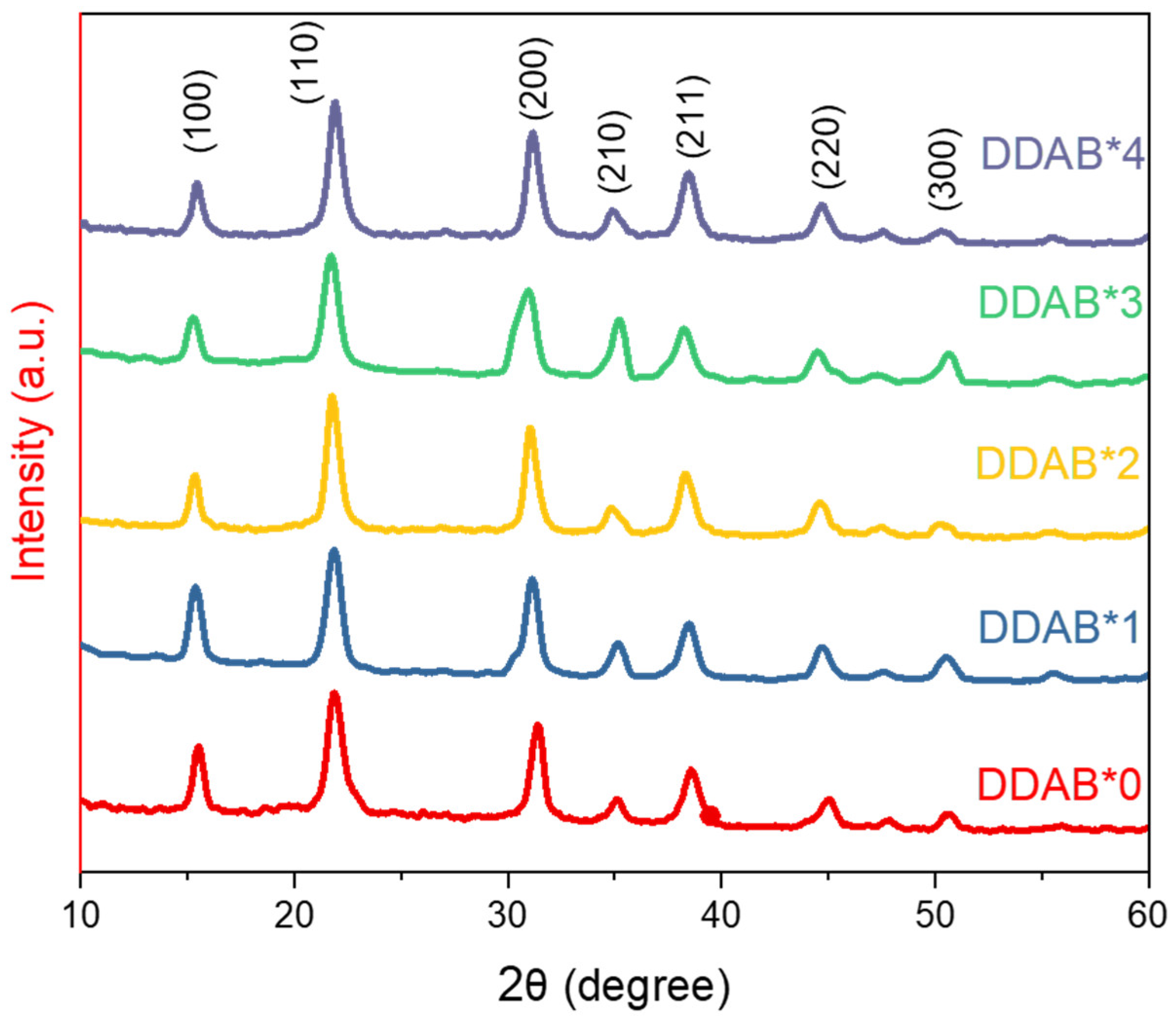
Figure 1. Photo images under (a) ambient light and (b) UV light of 365 nm; (c) PL, (d) absorption and (e) TRPL spectra of CsPbClxBr3−x PQDs with different DDAB concentrations.
Nanomaterials 12 03957 g001
Figure 2. TEM images of CsPbClxBr3−x PQDs treated by different DDAB concentrations.
Nanomaterials 12 03957 g002
Figure 3. The diameter distribution of CsPbClxBr3−x PQDs treated by (a) DDAB*0, (b) DDAB*1, (c) DDAB*2, (d) DDAB*3, and (e) DDAB*4. (f) The mean diameters of PQDs with different DDAB concentrations.
Nanomaterials 12 03957 g003
Figure 4. XRD pattern of CsPbClxBr3−x PQDs treated by different DDAB concentrations.
Nanomaterials 12 03957 g004
Figure 5. AFM images of the films coated with CsPbClxBr3−x PQDs treated by (a) DDAB*0, (b) DDAB*1, (c) DDAB*2, (d) DDAB*3, and (e) DDAB*4. (f) The root mean square roughness (Rq) of PQD films coated with different DDAB concentrations.
Nanomaterials 12 03957 g005
Figure 6. (a) Schematic diagram of structure and (b) energy level diagram of the blue PQLED device; (c) luminance−voltage curve, (d) current−voltage curve, (e) EQE−voltage curve and (f) EL spectra of the PQLED device based on CsPbClxBr3−x PQDs treated by different DDAB concentrations. The inset in (f) is the photo of DDAB*2 Device.
Nanomaterials 12 03957 g006
Table 1. XRD peak positions of CsPbClxBr3−x PQDs treated by different DDAB concentrations.
(hkl)(100)(110)(200)(210)(211)(220)(300)
DDAB*02θ(degree)15.5021.9231.3835.0838.6844.9650.73
d-spaceing(Å)5.7120854.0523822.848772.5562682.3262022.0138991.798275
DDAB*12θ(degree)15.3721.8631.1335.2838.4344.6350.48
d-spaceing(Å)5.7601044.0633712.8710792.5422312.340762.0288791.806594
DDAB*22θ(degree)15.3221.8131.0334.7838.2844.5850.28
d-spaceing(Å)5.7787914.0725762.8801052.577632.3495872.0310381.813311
DDAB*32θ(degree)15.3021.7831.0334.7838.2844.5350.13
d-spaceing(Å)5.78634.0781192.8801052.577632.3495872.0332031.818385
DDAB*42θ(degree)15.2621.7230.9335.2838.2344.5350.63
d-spaceing(Å)5.8013774.0892512.889192.5422312.3525462.0332031.801592
Publisher’s Note: MDPI stays neutral with regard to jurisdictional claims in published maps and institutional affiliations.

