Article

Boosting CdS Photocatalytic Activity for Hydrogen Evolution in Formic Acid Solution by P Doping and MoS2 Photodeposition

1
Key Laboratory for Biobased Materials and Energy of Ministry of Education, College of Materials and Energy, South China Agricultural University, 483 Wushan Road, Guangzhou 510642, China
2
School of Chemistry and Chemical Engineering, Lingnan Normal University, Zhanjiang 524048, China
3
Guangdong Laboratory for Lingnan Modern Agriculture, 483 Wushan Road, Guangzhou 510642, China
*
Authors to whom correspondence should be addressed.
Nanomaterials 2022, 12(3), 561; https://doi.org/10.3390/nano12030561
Submission received: 24 December 2021 / Revised: 25 January 2022 / Accepted: 1 February 2022 / Published: 6 February 2022
(This article belongs to the Section Energy and Catalysis)

Abstract

:
Formic acid is an appealing hydrogen storage material. In order to rapidly produce hydrogen from formic acid under relatively mild conditions, high-efficiency and stable photocatalytic systems are of great significance to prompt hydrogen (H2) evolution from formic acid. In this paper, an efficient and stable photocatalytic system (CdS/P/MoS2) for H2 production from formic acid is successfully constructed by elemental P doping of CdS nanorods combining with in situ photodeposition of MoS2. In this system, P doping reduces the band gap of CdS for enhanced light absorption, as well as promoting the separation of photogenerated charge carriers. More importantly, MoS2 nanoparticles decorated on P-doped CdS nanorods can play as noble-metal-free cocatalysts, which increase the light adsorption, facilitate the charge transfer and effectively accelerate the hydrogen evolution reaction. Consequently, the apparent quantum efficiency (AQE) of the designed CdS/P/MoS2 is up to 6.39% at 420 nm, while the H2 evolution rate is boosted to 68.89 mmol·g−1·h−1, which is 10 times higher than that of pristine CdS. This study could provide an alternative strategy for the development of competitive CdS-based photocatalysts as well as noble-metal-free photocatalytic systems toward efficient hydrogen production.

1. Introduction

With the rapid development of modern industry and inexhaustible energy consumption, hydrogen energy has attracted tremendous attention as a clean and efficient energy source. In order to use hydrogen energy in a scalable and convenient manner, hydrogen storage and transportation are of vital importance. Formic acid is an ideal material for hydrogen storage due to its high hydrogen proportion [1], low cost, low toxicity and high stability [2]. In order to extract hydrogen from formic acid for better utilization, traditional methods have adopted gold [3], silver [4], palladium [5] and other precious metals as catalysts to degrade formic acid to produce hydrogen under high temperature conditions. Such expensive catalysts and harsh reaction conditions limit the further development and application of formic acid in hydrogen storage.
Recently, the photocatalytic H2 evolution from formic acid by directly using clean solar energy has intrigued widespread attention [6], in terms of the advantages of not only being eco-friendly and the abundance of solar energy, but also the fact that relatively mild conditions and pollution-free products are involved in the photocatalytic process. Photocatalysis was first discovered in the 1970s by Fujishima and Honda [7]. Since then, a large number of photocatalysts have been continuously developed, and some of them have been used for photocatalytic H2 evolution from formic acid, such as g-C3N4 [8], SrTiO3 [9], ZnO [10], ZnS [11], CdS [12], etc. Among numerous semiconductor photocatalysts, CdS can be excited by visible light due to its band gap of about 2.4 eV, which makes it a promising photocatalytic candidate [13]. However, it has been proved that CdS always suffer from fast recombination of photogenerated charge carriers and severe photocorrosion, which seriously block the improvement of the photocatalytic efficiency of CdS photocatalysts [14,15]. In order to improve the light utilization and photocatalytic efficiency of CdS, commonly used solutions include element doping [16,17], cocatalyst loading [18,19,20,21] and the construction of heterojunctions [19,22,23,24]. Especially, elemental phosphorus (P) has been introduced into the CdS lattice to reduce the free energy of H2 adsorption and enhance its visible light absorption and corrosion resistance [24,25,26]. Moreover, Huang et al. has demonstrated that gradient doping of P in CdS can generate an oriented built-in electric field, thus improving the efficiency of charge extraction [25]. In addition to element doping, the loading of appropriate cocatalysts is also a very effective way to improve the photocatalytic efficiency of CdS. Generally speaking, after loading a suitable cocatalyst, the photogenerated electrons or holes of photocatalyst will quickly migrate to the cocatalyst for photocatalytic reactions, thereby greatly promoting the separation rate of photogenerated charge carriers [27]. Furthermore, the introduction of desirable cocatalysts can reduce the energy barrier required for redox reactions on the photocatalyst surfaces [27]. Noble metals, such as platinum [28] and gold [29], have been widely used in the construction of efficient photocatalytic systems because of their good cocatalytic activity, high conductivity and acceptable stability. Due to the scarcity of noble metals and the high cost, cocatalysts without noble metals are preferred so as to build a low-cost photocatalytic system that can be widely promoted. For example, CoxOy [30,31], MoS2 [19], MoN [32], NixP [33], CoxP [6], MoP [34], Co3C [35], Ni3C [36], CoFe2O4 [37], and NiFe2O4 [38,39] have been widely studied and made encouraging progress. Among them, 2D structured MoS2 has excellent H2 evolution reaction activity and high specific surface, which make it as very prospective cocatalyst. On the basis of a few studies on CdS/MoS2, it has been proved that the charge separation rate of CdS can be enhanced by loading with MoS2 and the corresponding photocatalytic performance of H2 evolution from formic acid can be also improved [40]. However, the photocatalytic H2 evolution rate of formic acid to H2 in the reported CdS/MoS2 systems are still not ideal. In order to release hydrogen energy from formic acid more quickly, it is necessary to establish a photocatalytic system based on CdS and MoS2 with higher photocatalytic activity that has the ability of rapid photocatalytic H2 production from formic acid. Yang et al. has demonstrated that P-doped CdS with MoSe2 cocatalysts can greatly improve the performance of photocatalyst [41]. Evidently, elemental P doping combined with MoS2 loading could be potentially effective to improve the photocatalytic activity of CdS for H2 evolution.
Based on above considerations, in this work, CdS nanorods are doped with elemental P (denoted as CdS/P), and then loaded with MoS2 on the surfaces by in situ photodeposition (denoted as CdS/P/MoS2), aiming to prepare an efficient and stable photocatalytic system of H2 evolution from formic acid. The as-prepared CdS/P/MoS2 system shows significantly enhanced photocatalytic activity and stability compared with pristine CdS. The apparent quantum efficiency (AQE) of the CdS/P/MoS2 is as high as 6.39% at 420 nm, while the H2 evolution rate is up to 68.89 mmol·g−1·h−1, which is 10 times higher than that of pristine CdS.

2. Materials and Methods

2.1. Preparation of the CdS Nanorods

A total of 4.627 g of cadmium nitrate tetrahydrate, 3.425 g of thiourea, and 65 mL of ethylene diamine were added to a 100 mL hydrothermal reaction kettle. After electromagnetic stirring for 30 min, the reaction system was sealed, heated to 160 °C, and kept for 48 h. After the hydrothermal reactor was naturally cooled to room temperature, the reaction product was centrifuged, washed with 95% ethanol for three times, and dried at 60 °C for 24 h. The received product was CdS nanorods.

2.2. Phosphating of CdS Nanorods

A total of 500 mg of sodium hypophosphite (NaH2PO2) and 500 mg of CdS nanorods were grinded together evenly. Then, the mixture was calcined at 300 °C for 2 h in a slow N2 flow. Finally, the calcined mixture was washed with deionized water and dried, and CdS/P was obtained.

2.3. Preparation of CdS/P/MoS2 and CdS/MoS2

CdS/P/MoS2 and CdS/MoS2 were prepared by in situ photodeposition. A total of 50 mg of CdS/P or CdS was mixed with 100 mL deionized water, followed by ultrasonic dispersion for 20 min. The uniformly dispersed suspension was then added with a certain amount of ammonium tetrathiomolybdate solution. N2 was continuously injected into the suspension and stirred for 30 min to remove oxygen from the suspension. After injection, the suspension was continuously irradiated with visible light for 1 h (300 W xenon lamp installed with 400 nm cut-off filter, input voltage of 220 V, current of 20 A, Beijing Perfectlight, PLS-SXE300D). After the illumination, the precipitation was recovered by filtration. After being washed with deionized water for three times, and being washed with 95% ethanol, the precipitates were dried in an oven at 60 °C for 12 h to obtain CdS/P/MoS2 or CdS/MoS2, respectively.

2.4. Performance Test of Photocatalytic Hydrogen Evolution

A total of 10 mg of the photocatalyst prepared above were taken and dispersed in 80 mL deionized water by ultrasonic. After the ultrasonic dispersion, 20 mL formic acid was added into the suspension, and N2 was continuously injected for 30 min to remove the dissolved oxygen in the suspension. After the deoxygenated suspension was irradiated by xenon lamp (installed with 400 nm cut-off filter, input voltage of 220 V, current of 20 A, Beijing Perfectlight, PLS-SXe300D), the generated H2 was detected by Techcomp GC 7900 installed with a TCD detector. The apparent quantum efficiency (AQE) was calculated by following formula [2,42,43]:
AQE = Number   of   evolved   H 2   molecules   ×   2 Number   of   incident   photons × 100 %

2.5. Characterizations

Powder X-ray diffraction (XRD) measurements were recorded on a Rigaku D/MAX-2500 diffractometer with monochromatized Cu Kα radiation (λ = 0.15418 nm). TEM, HRTEM and EDX mapping were recorded on the FEI Glacios Cryo-TEM equipped with an energy dispersive X-ray (EDX) spectroscope, operating at 200 kV. X-ray photoelectron spectra (XPS) were recorded on a VG ESCALAB 250Xi spectrometer, using a standard Al Kα X-ray source (300 W) and an analyser pass energy of 20 eV. Samples were mounted using double-sided adhesive tape and the binding energies were referenced to the C (1 s) binding energy of adventitious carbon contamination taken to be 284.7 eV. UV-vis absorption spectroscopy was conducted on a Shimadzu-2501 PC spectrophotometer using an integrating-sphere accessory. Room temperature photoluminescence (PL) spectra were recorded on a PerkinElmer LS 50B fluorescence spectrophotometer with an excitation wavelength of 300 nm. The PL decay plots were conducted on an Edinburgh Instruments F980 fluorescence lifetime spectrophotometer.

2.6. Photoelectrochemical Measurements

The preparation process of the photoelectrode was as follows: 10 mg photocatalyst, 2 mL anhydrous ethanol, 100 μL 5 wt.% Nafion solution were mixed and performed under ultrasonic for 30 min to obtain the evenly mixed suspension. A total of 400 μL suspension was dropped onto the FTO glass substrate (2 cm × 6 cm) and dried under an infrared lamp. Then, the FTO glass base was put into the porcelain ark and placed in a tubular furnace, which was heated to 150 °C at 3 °C min−1 and kept for 1 h under nitrogen protection, and finally cooled naturally to room temperature. The optical electrode was prepared by cutting the FTO glass substrate into 1 cm × 2 cm with a laboratory glass cutter. CHI 650E electrochemical workstation was used to form a three-electrode test system for photoelectrochemistry tests with the above prepared photoelectrode as the working electrode, of platinum sheet as the counter electrode and Ag/AgCl as the reference electrode. A 300 W xenon lamp was adopted as the light source. The polarization curves of the electrochemical H2 evolution reaction, transient photocurrent response test, Mott–Schottky test and electrochemical impedance test were carried out in 0.5 M sodium sulphate solution, and the polarization curves of the electrochemical oxygen evolution reaction were tested in 1 M KOH solution. Transient photocurrent response was tested using an applied voltage of 0.4 V. The scanning speed of the polarization curves was 0.005 V·s−1. Electrochemical impedance tests were performed with an amplitude of 0.005 V and frequencies of 0.01–105 Hz. The Mott–Schottky test was performed by an amplitude of 0.005 V and a frequency of 1000 Hz. The flat band potential was estimated using a Mott–Schottky curve via the following formula [44]:
1 C 2 = [ 2 e 0 ɛ · ɛ 0 N d A 2 ] · [ E E f b K T e ]  
The potentials to the Ag/AgCl electrode were calibrated to that of the reversible hydrogen electrode (RHE) and calculated by the following formula:
E R H E = E A g C l + 0.059 × p H + E A g C l Θ ( E A g C l Θ = 0.197   V )  

3. Results and Discussion

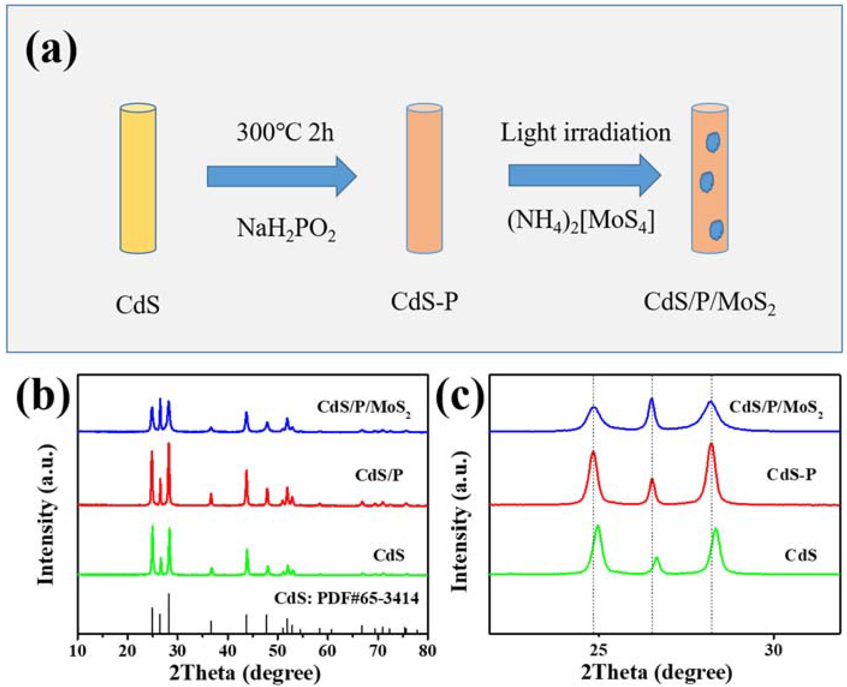
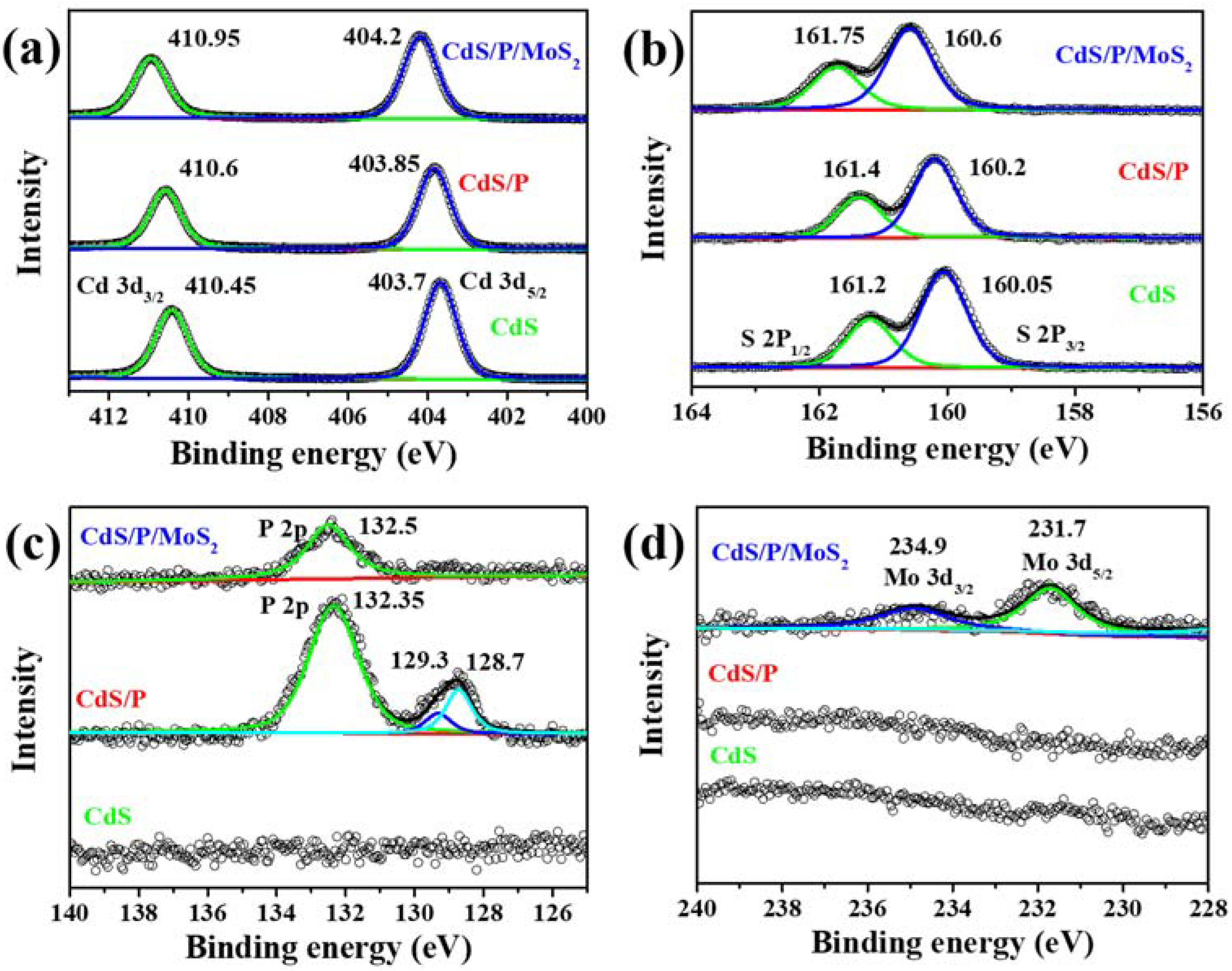
3.1. Characterization of the Composition, Structure and Morphology of the Photocatalysts

As shown in Figure 1a, NaH2PO2 was used as the P source to generate PH3 gas at 300 °C. PH3 gas can react with CdS nanorods to generate CdS/P. With ammonium tetrathiomolybdate as the precursor, the reaction of loading MoS2 on the surface of CdS/P by in situ photodeposition is shown below:
CdS / P h ν e + h + [ M o S 4 ] 2 + 2 e M o S 2 + 2 S 2
First, CdS/P produced photo-generated electrons and holes under the visible light irradiation. Then, [MoS4]2− adsorbed on the surface of CdS/P nanorods was reduced to MoS2 by the photogenerated electrons transferred to the surface of the CdS/P nanorods, thereby forming CdS/P/MoS2. Finally, the photo-generated holes were consumed through the oxidation of water molecules.
The XRD patterns of CdS, CdS/P, CdS/P/MoS2 are shown in Figure 1b. All diffraction peaks of CdS/P and CdS/P/MoS2 can be well attributed to the characteristic peaks of CdS (PDF#:65-3414). As shown in Figure 1c, compared with the diffraction peaks of CdS, three peaks of CdS/P and CdS/P/MoS2 shift to lower angles, suggesting that elemental P was successfully doped into the lattices of CdS [26,45,46]. As shown in Figure 1c, the intensity ratio of the three diffraction peaks of CdS is 2.7 (100):1.0 (002):2.6 (101), while the intensity ratio of the three diffraction peaks of CdS/P is 2.0:1.0:2.3. Compared to CdS, the peak intensity ratio of the (100) plane of CdS/P is decreased, which may affect the photocatalytic performance. Qiao et al. has demonstrated that the (100) plane of CdS benefits its photocatalytic activity [47]. Due to the low content of MoS2, no diffraction peaks belonging to MoS2 are observed in CdS/P/MoS2. Compared with those of CdS/P, the diffraction peak intensities of the (100) crystal plane at 24.84° and the (101) crystal plane at 28.22° for CdS/P/MoS2 have a slight decrease, indicating that the in situ photodeposition of MoS2 is selective.
TEM observation showed that CdS/P/MoS2 still maintained the basic nanorod morphology as CdS and CdS/P (Figure 2a). MoS2 loading on the surface of CdS/P/MoS2 can be viewed by HRTEM (Figure 2b). It can be seen from Figure 2b that there are typical lattice fringes of the (002) plane with a width of 0.34 nm of CdS [48] in the middle of the nanorod, and the lattice fringes of the (002) plane with a width of 0.61 nm of MoS2 [48,49] were attached to the outer edges of the nanorods. Element mappings (Figure 2c) also prove that Cd, S, P and a small amount of Mo are evenly distributed throughout the nanorods.
The surface composition of CdS/P/MoS2 was further analyzed by XPS and shown in Figure 3. Observing from Figure 3a, the peaks at 410.45 and 403.7 eV in CdS correspond to Cd 3d3/2 and Cd 3d5/2, which prove that Cd exists in the state of Cd2+ [50]. It can be concluded from Figure 3b that the peaks at 161.2 and 160.05 eV in CdS correspond to S 2P1/2 and S 2P3/2, which prove that S exists in the state of S2− [50]. When CdS was doped with phosphorus, the binding energy of Cd and S are almost unchanged, so it can be seen that phosphorus doping has no obvious effect on the chemical structure of CdS. As can be observed from Figure 3c, the peaks at 132.35 eV in CdS/P correspond to P 2p, which proves that P is successfully doped into CdS. The peaks at 129.3 and 128.7 eV demonstrate that some of P atoms exist in the form of zero-valent phosphorus [26]. In view of the integral area of the peaks, and atomic sensitivity factors, the atomic percentages of Cd, S, doped P and zero valence P of CdS/P are calculated to be 44.3 at.%, 44.0 at.%, 9.6 at.% and 2.1 at.%, respectively. After MoS2 loading, the peaks of Cd, S and P in CdS/P/MoS2 move to the direction of high binding energy, which indicates that a heterojunction is formed between CdS/P and MoS2 and is favorable for the charge transfer of photogenerated electrons from CdS/P to MoS2 [49]. It is worth noting that there is no zero-valent phosphorus in CdS/P/MoS2 after in situ photodeposition. This is because zero-valent phosphorus is unstable and is more likely to be oxidized during in situ photodeposition. However, P 2p still exists at 132.5 eV, which proves the stable existence of P doping. As shown in Figure 3d, there are two tiny peaks at 234.9 and 231.7 eV, corresponding to Mo 3d3/2 and Mo 3d5/2, respectively, indicating that Mo element exists in the form of Mo4+ [49]. Based on the integral area of the peaks, and atomic sensitivity factors, the atomic percentages of Mo, Cd, S, and P in CdS/P/MoS2 were calculated to be 0.6 at.%, 47.1 at.%, 48.4 at.%, and 3.9 at.%, respectively. The results of XPS further confirmed the coexistence of doped P and MoS2 in CdS/P/MoS2.

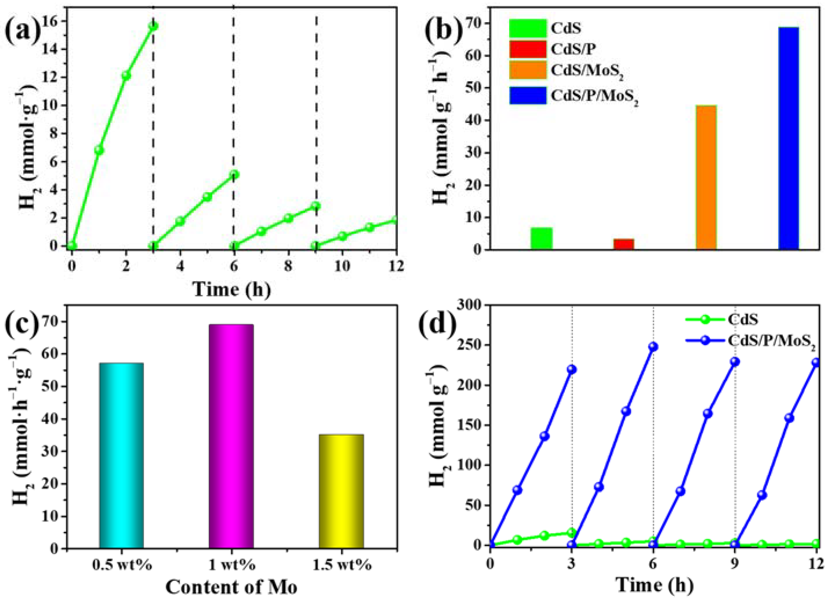
3.2. The Performances of the Photocatalysts for Photocatalytic H2 Evolution

The activities of the photocatalysts for photocatalytic H2 evolution from formic acid solution were evaluated under visible light. As shown in Figure 4a, the photocatalytic activity and stability of pure CdS nanorods are very poor. Its activity of H2 evolution from formic acid solution decayed rapidly within 12 h.
Figure 4b shows the H2 evolution rate of CdS, CdS/P, CdS/MoS2 and CdS/P/MoS2 under visible light irradiation. The H2 evolution rate of pure CdS nanorods is 6.8 mmol g−1 h−1. However, the rate of H2 evolution for CdS/P decreased (3.4 mmol g−1 h−1) while P was doped. In CdS/P, a small amount of zero-valent P covers the surface of the catalyst, resulting in the attenuation of the (100) plane (Figure 1c) and the increase in the interfacial resistance (Figure 5d). This could explain the decrease in the catalytic performance of CdS/P. The in situ photodeposition of MoS2 (noting that the theoretical content of Mo is 1%) on the surface of CdS significantly increased the rate of H2 evolution to 44.6 mmol g−1 h−1, indicating that MoS2 is indeed an excellent H2 evolution cocatalyst. When MoS2 (the theoretical content of Mo is still 1%) was loaded onto the surface of CdS/P, the rate of H2 evolution was further increased to 68.9 mmol g−1 h−1, indicating that P doping and MoS2 loading could synergistically promote the photocatalytic activity of CdS for H2 production. In order to find out the optimal doping amount of P, the effect of different NaH2PO2 dosage on the hydrogen production performance of CdS/P/MoS2 was evaluated (Figure S1). When the dosage of NaH2PO2 is 500 mg, that is, the mass ratio of NaH2PO2 to CdS is 1:1, the catalyst has the best performance. As shown in Figure 4c, CdS/P loaded with MoS2 (1 wt.% of Mo) shows the highest H2 evolution rate of 68.9 mmol g−1 h−1 in the formic acid solution, indicating that the theoretical Mo loading (1 wt %) is the best. The photocatalytic hydrogen production performance of CdS loaded with different MoS2 were also tested, and the optimal loading is consistent with CdS/P/MoS2 (Figure S2a). In the stability test of CdS/MoS2, the performance of CdS/MoS2 was slightly weakened after 12 h photocatalytic hydrogen production test, though its stability was still greater than that of CdS (Figure S2b). The results show that the elaborate loading of MoS2 is beneficial to improve the photocatalytic stability of CdS. Figure 4d shows the photocatalytic stabilities of CdS and CdS/P/MoS2 in the formic acid solution. After four cycles of testing within 12 h, the rate of H2 evolution for CdS/P/MoS2 did not decrease significantly. With regard to pure CdS nanorods, it can be seen from Figure 4a that only 12.5% of the initial photocatalytic activity was retained after four cycles within 12 h. Evidently, the stability of CdS/P/MoS2 after P doping and in situ photodeposition of MoS2 was greatly improved compared with that of CdS. The excellent stability of CdS/P/MoS2 can also be confirmed by XRD and TEM characterization (Figure S3, see Supplementary Materials for details) and XPS spectra (Figure S4). Figure S3 demonstrated that the exact structure of CdS/P/MoS2 does not change significantly before and after the photocatalytic reaction for 12 h. In addition, as shown in Figure 6a, the apparent quantum efficiencies of CdS/P/MoS2 at 420 nm, 450 nm, 500 nm and 600 nm are 6.39%, 4.57%, 3.05%, and 2.14%, respectively. The photocatalytic performances of CdS/P/MoS2 to degrade formic acid for hydrogen production were compared with those of the recently reported photocatalysts in Table S1 [2,6,12,51,52,53,54,55,56,57], which indicates the application potential of P-doping and MoS2 engineered CdS nanorods for the photocatalytic decomposition of formic acid.

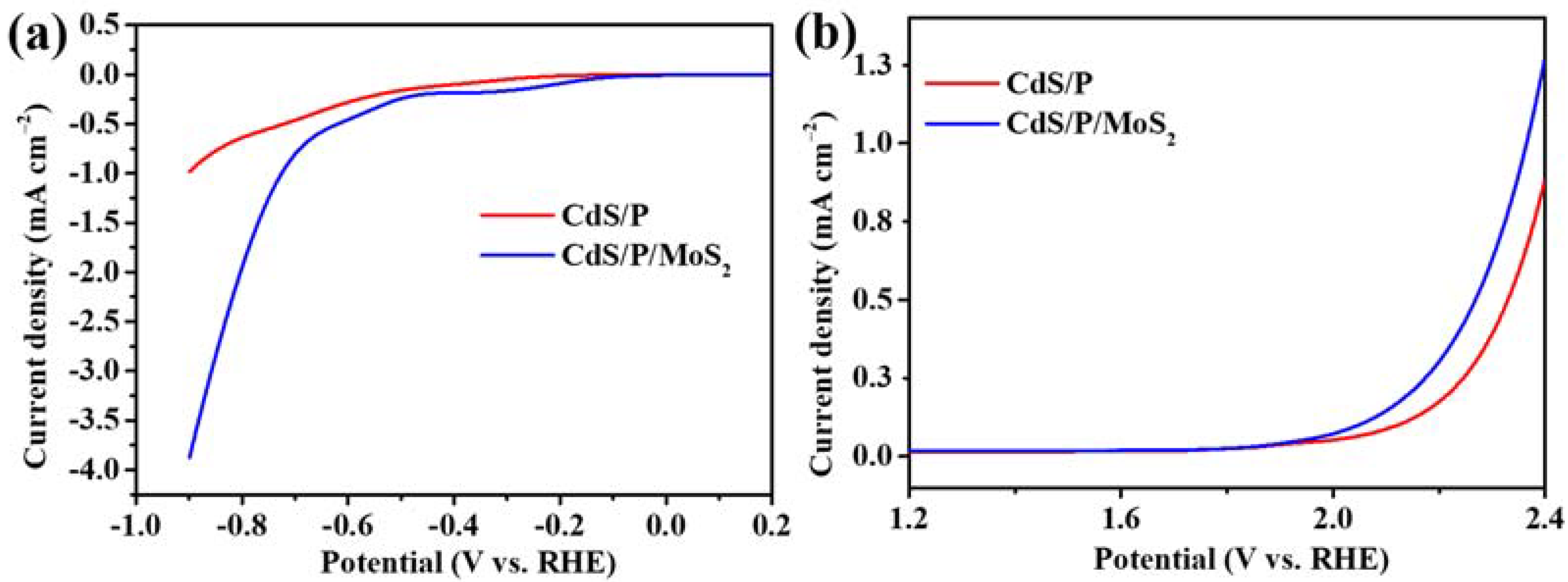
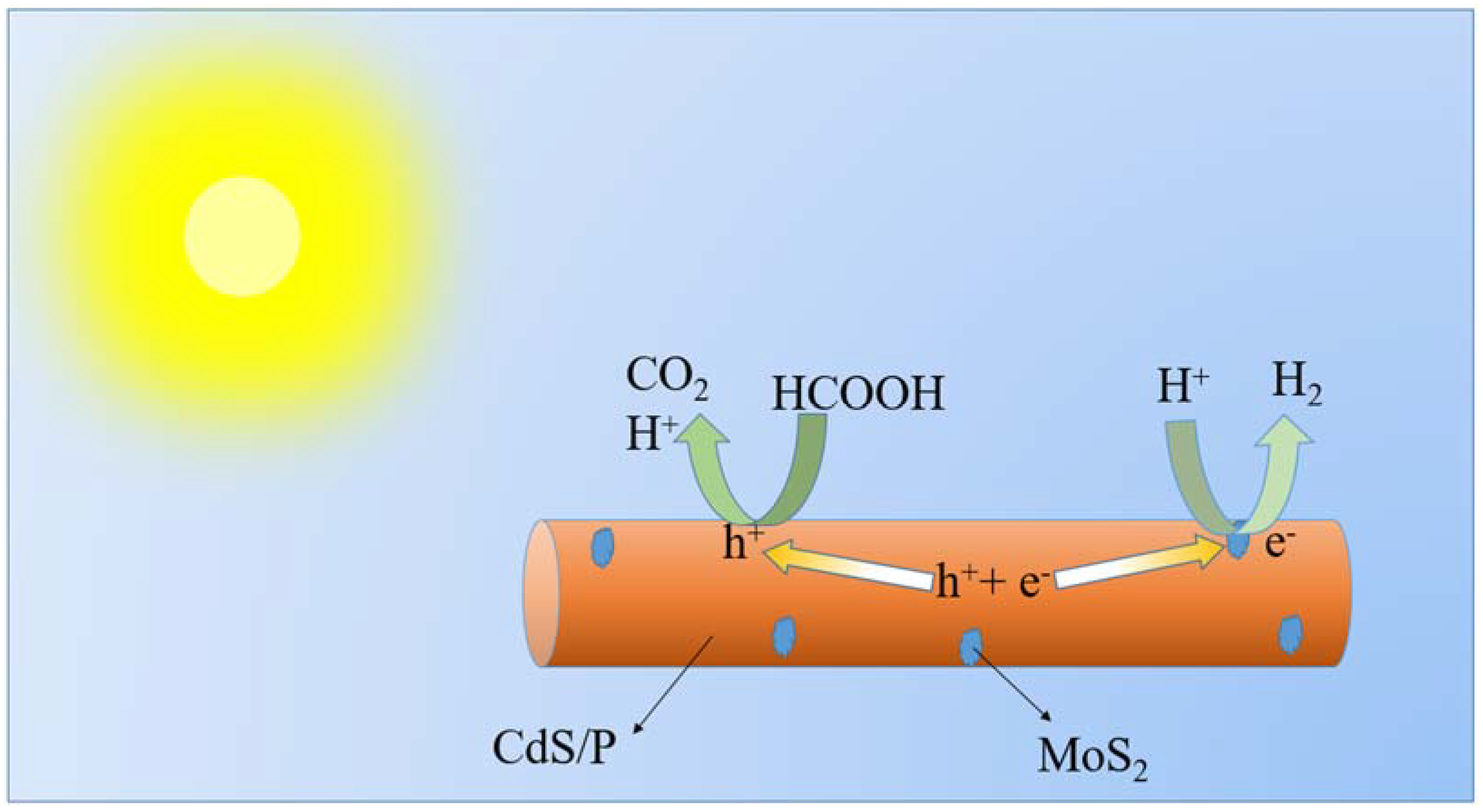
3.3. The Mechanism of Photocatalytic H2 Evolution in Formic Acid Solution

In general, broadening the light absorption range of photocatalysts can increase the amount of photogenerated charges, which are beneficial for subsequent photocatalytic redox reactions. It can be seen from Figure 6a that the light absorption band of CdS extends from the ultraviolet region to ~530 nm. After P doping, the absorption of CdS/P in the visible light range increases significantly, indicating that the introduction of the P element improves the light absorption capacity of CdS [26,58]. Moreover, the light absorption of CdS/P/MoS2 after MoS2 photodeposition is significantly enhanced from wavelength 300 nm to 800 nm, which is attributed to the effective light absorption by MoS2 [40].
The band gaps of CdS, CdS/P, and CdS/P/MoS2 were calculated by the Kubelka–Munk method based on the absorption spectrum [40]. As shown in Figure 6b, the value of the band gap was obtained by extrapolating the tangents at (αhν)2 = 0 when plotting (αhν)2 versus hν, where hν is the photon energy and α is the absorption coefficient. P doping narrows the band gap of CdS to 2.36 eV compared to CdS (2.42 eV). Additionally, the band gap of CdS/P/MoS2 is 2.34 eV. Evidently, CdS/P/MoS2 has a better light-harvesting capability to boost the photogenerated charge generation for the H2 evolution reaction in the formic acid solution.
The Mott–Schottky test results can confirm the band locations and help to resolve the charge migration paths in CdS/P/MoS2. As can be seen from the results (Figure 6c), the slope of CdS, CdS/P and CdS/P/MoS2 curves is positive, which proves that the three samples own n-type semiconductor characteristics [59]. As to the MS curve, the value of the X-axis intercept of the tangent line in the linear part is the flat band potential (Vfb) of the sample. According to Figure 6c, the flat-band potential of CdS is −0.56 V vs. RHE, while the flat-band potential of CdS/P is −0.53V vs. RHE, and the flat-band potential of CdS/P/MoS2 is −0.37V vs. RHE. By comparing the flat band potential of the three samples, it can be found that the flat band potential of CdS/P is more positive than that of CdS, which means that the doping of P leads to the downward shift of the conduction band bottom in CdS/P [26,59]. Compared with CdS/P, the conduction band bottom of CdS/P/MoS2 moves down further, which is due to the more positive feature of the Fermi level of MoS2 compared with CdS/P. When a close contact is formed between CdS/P and MoS2, the electrons transfer from CdS/P to MoS2, resulting in band bending, which makes the Fermi level reach a new equilibrium [26,60]. Based on the above flat band potential data and band gap width, in combination with the rule that the conduction band of N-type semiconductor is more negative than the flat band by about −0.1 V, we can conclude the following band structure diagram. As can be seen from Figure 6d, the photogenerated electrons tend to transfer to MoS2, and the photogenerated holes tend to transfer to the surface of CdS/P. The above results indicate that the constructed CdS/P/MoS2 photocatalytic system can promote the charge separation and improve the photocatalytic efficiency.
In order to further characterize the charge transfer and separation ability of CdS/P/MoS2, optical and photoelectrochemical tests were performed. Photoluminescence (PL) spectroscopy can be used to test the separation and recombination tendency of photogenerated charge carriers. As can be seen in Figure 5a, CdS exhibits a strong fluorescence emission peak at around 540 nm, while the fluorescence intensity of CdS/P and CdS/P/MoS2 in the same region is much weaker than that of CdS. This means that the photogenerated charge carriers in CdS tend to recombine due to the structural limitation of individual CdS, while the photogenerated charge carriers in CdS/P and CdS/P/MoS2 tend to rapidly separate and reduce the recombination due to the change of the band structure caused by P doping and MoS2 loading. It should be noted that there is no obvious difference in fluorescence intensity between CdS/P and CdS/P/MoS2. This can prove that MoS2 loading does not increase the fluorescence intensity of the sample, that is, does not obviously impact the recombination of the photogenerated charges. Since P doping has greatly reduced the fluorescence emission peak that nearly disappeared, it is difficult to detect the decrease in fluorescence intensity after MoS2 loading. These results indicate that CdS/P and CdS/P/MoS2 have a higher light utilization ability than CdS, thus improving the efficiency of photocatalysis. Fluorescence lifetime tests were used for a more detailed analysis of the photogenerated charge carriers of the samples (Figure 5b). Through double exponential function fitting and calculation, the average fluorescence lifetime of the sample was calculated, as shown in Table S2. The average lifetime of CdS/P/MoS2 is 1.05 ns, which is much lower than that of CdS/P (2.51 ns) and CdS (2.66 ns). This proves that CdS/P/MoS2 has a higher nonradiative transition rate, which is attributed to the accelerated transfer of electrons from CdS/P to MoS2 [58]. Ac impedance spectroscopy (Figure 5d) was further used to analyze the interfacial resistance of the photocatalysts. In the Nyquist plots, the smaller arc represents a smaller interfacial resistance, meaning that the charges can be transferred more easily from the surface of the catalysts to the solution [61]. It can be seen that the arc of CdS/P is larger than that of CdS, which could be caused by the small amount of red phosphorus attached to the surface of CdS/P, and increases the interfacial resistance between CdS/P and the solution. It is worth noting that with the loaded MoS2, the interface resistance of CdS/P/MoS2 decreases significantly compared to CdS/P, indicating that the presence of MoS2 is very conducive to the charge transfer in the semiconductor photocatalyst. Transient photocurrent response was used to further clarify the ability of the photocatalyst to inhibit the recombination of photogenerated electrons and holes. As shown in Figure 5c, the current density of CdS/P is significantly higher than that of CdS. Although CdS/P has a higher interfacial resistance than CdS, it is difficult for the charges on the surface of CdS/P to transfer to the solution. However, as the doping of P can change the energy band structure of the photocatalyst and improves the light response range, the photogenerated charges are more easily to be transferred from the inside of CdS/P to the surface, resulting in an increase in the photocurrent. The photocurrent of CdS/P/MoS2 is significantly higher than that of CdS/P. This indicates that the interfacial interaction between CdS/P and MoS2 leads to the rapid migration of photogenerated electrons from CdS/P to MoS2, and therefore CdS/P/MoS2 achieved better photocatalytic performance due to its smaller interfacial resistance. All above optical and photoelectrochemical tests have proved that CdS/P/MoS2 owns a stronger light response and enhanced charge separation efficiency.
The effect of MoS2 as a cocatalyst in the photocatalytic process can be further characterized by the electrocatalytic hydrogen evolution reaction and oxygen evolution reaction, which in turn provide more clues to characterize the reactive activity of photocatalytic oxidation and reduction [62]. Figure 7 shows the electrocatalytic H2 evolution reaction (HER) curve and oxygen evolution reaction (OER) curves of CdS/P and CdS/P/MoS2 tested by linear sweep voltammetry. It can be seen that the in situ photodeposition of MoS2 can significantly reduce the HER and OER overpotentials at the same time. Therefore, it can be inferred that the conduction band of CdS is located in a more reductive zone compared to the composites (Figure 6d), but its H2 reduction rate seems to be less. This is because the kinetics of photocatalytic H2 evolution reaction on the surface of CdS is sluggish. The in situ photodeposited MoS2 cocatalyst can significantly reduce the dynamic barrier of H2 evolution reaction on the surfaces of CdS/P/MoS2 and CdS/MoS2. Therefore, after the loading of MoS2, the rate of photocatalytic H2 evolution for CdS/P/MoS2 and CdS/MoS2 are increased significantly.
Based on the above results, a reasonable mechanism of photocatalytic H2 evolution by CdS/P/MoS2 in the formic acid solution was summarized. As shown in Scheme 1, photoinduced charges are firstly generated when the photocatalyst receives light radiation. The Schottky energy barrier generated by the interfacial interaction between CdS/P and MoS2 can promote the transfer of the photogenerated electrons from CdS/P to the surface-loaded MoS2 cocatalyst. Photogenic holes remain in CdS/P and migrate to the surface. The combination of MoS2 as a cocatalyst with CdS/P could synergistically reduce the energy barriers of photocatalytic HER and OER, resulting in the reduction in H+ in the formic acid solution by photogenerated electrons in MoS2 to generate H2, while the photogenerated holes are consumed by formic acid. In summary, CdS/P/MoS2 photocatalyst can realize a significant efficiency in the photocatalytic H2 evolution in the formic acid solution.

4. Conclusions

In conclusion, we have demonstrated that elemental P doping combining with the in situ photodeposition of MoS2 can improve the photocatalytic activity and stability of CdS for H2 evolution from formic acid. The significantly enhanced photocatalytic activity of the CdS/P/MoS2 system resulted from the improved visible light absorption, the fast separation of photogenerated charge carriers and more exposed active sites of the surface engineered CdS for hydrogen evolution. The present study could provide a pathway to construct cost-efficient and durable noble-metal-free photocatalytic systems for H2 evolution from formic acid.

Supplementary Materials

The following supporting information can be downloaded at: www.mdpi.com/article/10.3390/nano12030561/s1. Figure S1: The average rate of H2 evolution over CdS/P/MoS2 synthesized from different dosage of NaH2PO2; Figure S2: The average rate of H2 evolution over CdS/MoS2 loaded with different contents of Mo (a) and stability tests of CdS and CdS/MoS2 (b); Figure S3: The characterization of CdS/P/MoS2 after recycling tests: (a) HRTEM; (b) XRD; Figure S4: The high resolution XPS spectra of CdS/P/MoS2 after a photocatalytic run: (a) Cd 3d; (b) S 2p; (c) P 2p and (d) Mo 3d; Table S1: Comparison of the photocatalytic H2 production activities of different photocatalyst; Table S2: Exponential decay-fitted parameters of fluorescence lifetime for CdS, CdS/P and CdS/P/MoS2.

Author Contributions

Methodology, J.L.; validation, C.G., Z.W. and X.Z.; formal analysis, X.Z.; data curation, J.L. and X.Z.; writing—original draft preparation, J.L. and H.H.; writing—review and editing, Y.F. and Z.W.; supervision, Z.W.; project administration, Y.F. All authors have read and agreed to the published version of the manuscript.

Funding

This research was funded by Laboratory of Lingnan Modern Agriculture Project, grant number NZ2021029 and the National Natural Science Foundation of China, grant number 21972048.

Institutional Review Board Statement

Not applicable.

Informed Consent Statement

Not applicable.

Data Availability Statement

Data can be available upon request from the authors.

Acknowledgments

This research was supported by Laboratory of Lingnan Modern Agriculture Project (NZ2021029) and the National Natural Science Foundation of China (21972048).

Conflicts of Interest

The authors declare no conflict of interest.

References

  1. Kuehnel, M.F.; Wakerley, D.W.; Orchard, K.L.; Reisner, E. Photocatalytic formic acid conversion on CdS nanocrystals with controllable selectivity for H2 or CO. Angew. Chem. Int. Ed. 2015, 54, 9627–9631. [Google Scholar] [CrossRef] [PubMed] [Green Version]
  2. Cao, S.; Chen, Y.; Wang, H.; Chen, J.; Shi, X.; Li, H.; Cheng, P.; Liu, X.; Liu, M.; Piao, L. Ultrasmall CoP nanoparticles as efficient cocatalysts for photocatalytic formic acid dehydrogenation. Joule 2018, 2, 549–557. [Google Scholar] [CrossRef] [Green Version]
  3. Gu, X.; Lu, Z.-H.; Jiang, H.-L.; Akita, T.; Xu, Q. Synergistic catalysis of metal–organic framework-immobilized Au–Pd nanoparticles in dehydrogenation of formic acid for chemical hydrogen storage. J. Am. Chem. Soc. 2011, 133, 11822–11825. [Google Scholar] [CrossRef] [PubMed]
  4. Zhang, S.; Metin, Ö.; Su, D.; Sun, S. Monodisperse AgPd alloy nanoparticles and their superior catalysis for the dehydrogenation of formic acid. Angew. Chem. Int. Ed. 2013, 52, 3681–3684. [Google Scholar] [CrossRef]
  5. Jiang, K.; Xu, K.; Zou, S.; Cai, W.-B. B-doped Pd catalyst: Boosting room-temperature hydrogen production from formic acid–formate solutions. J. Am. Chem. Soc. 2014, 136, 4861–4864. [Google Scholar] [CrossRef] [PubMed]
  6. Zhou, P.; Zhang, Q.; Xu, Z.; Shang, Q.; Wang, L.; Chao, Y.; Li, Y.; Chen, H.; Lv, F.; Zhang, Q.; et al. Atomically dispersed Co-P3 on CdS nanorods with electron-rich feature boosts photocatalysis. Adv. Mater. 2020, 32, 1904249. [Google Scholar] [CrossRef]
  7. Fujishima, A.; Honda, K. Electrochemical photolysis of water at a semiconductor electrode. Nature 1972, 238, 37–38. [Google Scholar] [CrossRef]
  8. Liu, H.; Liu, X.; Yang, W.; Shen, M.; Geng, S.; Yu, C.; Shen, B.; Yu, Y. Photocatalytic dehydrogenation of formic acid promoted by a superior PdAg≅g-C3N4 Mott–Schottky heterojunction. J. Mater. Chem. A 2019, 7, 2022–2026. [Google Scholar] [CrossRef]
  9. Guo, M.; Liu, Q.; Wu, M.; Lv, T.; Jia, L. Novel reduced graphene oxide wrapped-SrTiO3 flower-like nanostructure with Ti–C bond for free noble metal decomposition of formic acid to hydrogen. Chem. Eng. J. 2018, 334, 1886–1896. [Google Scholar] [CrossRef]
  10. Bulushev, D.A.; Zacharska, M.; Beloshapkin, S.; Guo, Y.; Yuranov, I. Catalytic properties of PdZn/ZnO in formic acid decomposition for hydrogen production. Appl. Catal. A Gen. 2018, 561, 96–103. [Google Scholar] [CrossRef]
  11. Villa, K.; Domènech, X.; Malato, S.; Maldonado, M.I.; Peral, J. Heterogeneous photocatalytic hydrogen generation in a solar pilot plant. Int. J. Hydrogen Energy 2013, 38, 12718–12724. [Google Scholar] [CrossRef]
  12. Wang, T.; Yang, L.; Jiang, D.; Cao, H.; Minja, A.C.; Du, P. CdS nanorods anchored with crystalline FeP nanoparticles for efficient photocatalytic formic acid dehydrogenation. ACS Appl. Mater. Interfaces 2021, 13, 23751–23759. [Google Scholar] [CrossRef]
  13. Li, Q.; Li, X.; Wageh, S.; Al-Ghamdi, A.A.; Yu, J. CdS/graphene nanocomposite photocatalysts. Adv. Energy Mater. 2015, 5, 1500010. [Google Scholar] [CrossRef]
  14. Kudo, A.; Miseki, Y. Heterogeneous photocatalyst materials for water splitting. Chem. Soc. Rev. 2009, 38, 253–278. [Google Scholar] [CrossRef] [PubMed]
  15. Hu, Y.; Gao, X.; Yu, L.; Wang, Y.; Ning, J.; Xu, S.; Lou, X.W. Carbon-coated CdS petalous nanostructures with enhanced photostability and photocatalytic activity. Angew. Chem. Int. Ed. 2013, 52, 5636–5639. [Google Scholar] [CrossRef]
  16. Li, S.; Wang, L.; Li, Y.; Zhang, L.; Wang, A.; Xiao, N.; Gao, Y.; Li, N.; Song, W.; Ge, L.; et al. Novel photocatalyst incorporating Ni-Co layered double hydroxides with P-doped CdS for enhancing photocatalytic activity towards hydrogen evolution. Appl. Catal. B Environ. 2019, 254, 145–155. [Google Scholar] [CrossRef]
  17. Zubair, M.; Vanhaecke, E.M.M.; Svenum, I.-H.; Rønning, M.; Yang, J. Core-shell particles of C-doped CdS and graphene: A noble metal-free approach for efficient photocatalytic H2 generation. Green Energy Environ. 2020, 5, 461–472. [Google Scholar] [CrossRef]
  18. Wang, Z.; Qi, Z.; Fan, X.; Leung, D.Y.C.; Long, J.; Zhang, Z.; Miao, T.; Meng, S.; Chen, S.; Fu, X. Intimately contacted Ni2P on CdS nanorods for highly efficient photocatalytic H2 evolution: New phosphidation route and the interfacial separation mechanism of charge carriers. Appl. Catal. B Environ. 2021, 281, 119443. [Google Scholar] [CrossRef]
  19. Shen, L.; Luo, M.; Liu, Y.; Liang, R.; Jing, F.; Wu, L. Noble-metal-free MoS2 co-catalyst decorated UiO-66/CdS hybrids for efficient photocatalytic H2 production. Appl. Catal. B Environ. 2015, 166–167, 445–453. [Google Scholar] [CrossRef]
  20. Wei, R.-B.; Huang, Z.-L.; Gu, G.-H.; Wang, Z.; Zeng, L.; Chen, Y.; Liu, Z.-Q. Dual-cocatalysts decorated rimous CdS spheres advancing highly-efficient visible-light photocatalytic hydrogen production. Appl. Catal. B Environ. 2018, 231, 101–107. [Google Scholar] [CrossRef]
  21. Li, Y.-L.; Wang, X.-J.; Hao, Y.-J.; Zhao, J.; Liu, Y.; Mu, H.-Y.; Li, F.-T. Rational design of stratified material with spatially separated catalytic sites as an efficient overall water-splitting photocatalyst. Chin. J. Catal. 2021, 42, 1040–1050. [Google Scholar] [CrossRef]
  22. Zhou, F.Q.; Fan, J.C.; Xu, Q.J.; Min, Y.L. BiVO4 nanowires decorated with CdS nanoparticles as Z-scheme photocatalyst with enhanced H2 generation. Appl. Catal. B Environ. 2017, 201, 77–83. [Google Scholar] [CrossRef]
  23. Hu, Y.; Hao, X.; Cui, Z.; Zhou, J.; Chu, S.; Wang, Y.; Zou, Z. Enhanced photocarrier separation in conjugated polymer engineered CdS for direct Z-scheme photocatalytic hydrogen evolution. Appl. Catal. B Environ. 2020, 260, 118131. [Google Scholar] [CrossRef]
  24. Shi, Y.; Zhang, B. Recent advances in transition metal phosphide nanomaterials: Synthesis and applications in hydrogen evolution reaction. Chem. Soc. Rev. 2016, 45, 1529–1541. [Google Scholar] [CrossRef]
  25. Huang, H.; Dai, B.; Wang, W.; Lu, C.; Kou, J.; Ni, Y.; Wang, L.; Xu, Z. Oriented built-in electric field introduced by surface gradient diffusion doping for enhanced photocatalytic H2 evolution in CdS nanorods. Nano Lett. 2017, 17, 3803–3808. [Google Scholar] [CrossRef]
  26. Shi, R.; Ye, H.-F.; Liang, F.; Wang, Z.; Li, K.; Weng, Y.; Lin, Z.; Fu, W.-F.; Che, C.-M.; Chen, Y. Interstitial P-doped CdS with long-lived photogenerated electrons for photocatalytic water splitting without sacrificial agents. Adv. Mater. 2018, 30, 1705941. [Google Scholar] [CrossRef]
  27. Li, X.; Yu, J.; Low, J.; Fang, Y.; Xiao, J.; Chen, X. Engineering heterogeneous semiconductors for solar water splitting. J. Mater. Chem. A 2015, 3, 2485–2534. [Google Scholar] [CrossRef]
  28. Yang, J.; Yan, H.; Wang, X.; Wen, F.; Wang, Z.; Fan, D.; Shi, J.; Li, C. Roles of cocatalysts in Pt–PdS/CdS with exceptionally high quantum efficiency for photocatalytic hydrogen production. J. Catal. 2012, 290, 151–157. [Google Scholar] [CrossRef]
  29. Wang, P.; Sheng, Y.; Wang, F.; Yu, H. Synergistic effect of electron-transfer mediator and interfacial catalytic active-site for the enhanced H2-evolution performance: A case study of CdS-Au photocatalyst. Appl. Catal. B Environ. 2018, 220, 561–569. [Google Scholar] [CrossRef]
  30. Zhang, C.; Liu, B.; Li, W.; Liu, X.; Wang, K.; Deng, Y.; Guo, Z.; Lv, Z. A well-designed honeycomb Co3O4≅CdS photocatalyst derived from cobalt foam for high-efficiency visible-light H2 evolution. J. Mater. Chem. A 2021, 9, 11665–11673. [Google Scholar] [CrossRef]
  31. Yuan, J.; Wen, J.; Gao, Q.; Chen, S.; Li, J.; Li, X.; Fang, Y. Amorphous Co3O4 modified CdS nanorods with enhanced visible-light photocatalytic H2-production activity. Dalton Trans. 2015, 44, 1680–1689. [Google Scholar] [CrossRef] [PubMed]
  32. Gong, S.; Jiang, Z.; Shi, P.; Fan, J.; Xu, Q.; Min, Y. Noble-metal-free heterostructure for efficient hydrogen evolution in visible region: Molybdenum nitride/ultrathin graphitic carbon nitride. Appl. Catal. B Environ. 2018, 238, 318–327. [Google Scholar] [CrossRef]
  33. Wang, Z.; Li, L.; Liu, M.; Miao, T.; Ye, X.; Meng, S.; Chen, S.; Fu, X. A new phosphidation route for the synthesis of NiPx and their cocatalytic performances for photocatalytic hydrogen evolution over g-C3N4. J. Energy Chem. 2020, 48, 241–249. [Google Scholar] [CrossRef]
  34. Yang, F.; Liu, D.; Li, Y.; Ning, S.; Cheng, L.; Ye, J. Solid-state synthesis of ultra-small freestanding amorphous MoP quantum dots for highly efficient photocatalytic H2 production. Chem. Eng. J. 2021, 406, 126838. [Google Scholar] [CrossRef]
  35. Irfan, R.M.; Tahir, M.H.; Iqbal, S.; Nadeem, M.; Bashir, T.; Maqsood, M.; Zhao, J.; Gao, L. Co3C as a promising cocatalyst for superior photocatalytic H2 production based on swift electron transfer processes. J. Mater. Chem. C 2021, 9, 3145–3154. [Google Scholar] [CrossRef]
  36. Shen, R.; Ding, Y.; Li, S.; Zhang, P.; Xiang, Q.; Ng, Y.H.; Li, X. Constructing low-cost Ni3C/twin-crystal Zn0.5Cd0.5S heterojunction/homojunction nanohybrids for efficient photocatalytic H2 evolution. Chin. J. Catal. 2021, 42, 25–36. [Google Scholar] [CrossRef]
  37. Lallimathi, M.; Kalisamy, P.; Suryamathi, M.; Alshahrani, T.; Shkir, M.; Venkatachalam, M.; Palanivel, B. Carbon dot loaded integrative CoFe2O4/g-C3N4 P-N heterojunction: Direct solar light-driven photocatalytic H2 evolution and organic pollutant degradation. ChemistrySelect 2020, 5, 10607–10617. [Google Scholar] [CrossRef]
  38. Palanivel, B.; Shkir, M.; Alshahrani, T.; Mani, A. Novel NiFe2O4 deposited S-doped g-C3N4 nanorod: Visible-light-driven heterojunction for photo-Fenton like tetracycline degradation. Diam. Relat. Mater. 2021, 112, 108148. [Google Scholar] [CrossRef]
  39. Palanivel, B.; Hu, C.; Shkir, M.; AlFaify, S.; Ibrahim, F.A.; Hamdy, M.S.; Mani, A. Fluorine doped g-C3N4 coupled NiFe2O4 heterojunction: Consumption of H2O2 for production of hydroxyl radicals towards paracetamol degradation. Colloid Interface Sci. Commun. 2021, 42, 100410. [Google Scholar] [CrossRef]
  40. Ma, S.; Xie, J.; Wen, J.; He, K.; Li, X.; Liu, W.; Zhang, X. Constructing 2D layered hybrid CdS nanosheets/MoS2 heterojunctions for enhanced visible-light photocatalytic H2 generation. Appl. Surf. Sci. 2017, 391, 580–591. [Google Scholar] [CrossRef]
  41. Yang, X.; Yang, H.; Zhang, T.; Lou, Y.; Chen, J. P-Doped CdS integrated with multiphasic MoSe2 nanosheets accomplish prominent photocatalytic activity for hydrogen evolution. Catal. Sci. Technol. 2021, 11, 5849–5858. [Google Scholar] [CrossRef]
  42. Song, J.; Zhao, H.; Sun, R.; Li, X.; Sun, D. An efficient hydrogen evolution catalyst composed of palladium phosphorous sulphide (PdP∼0.33S∼1.67) and twin nanocrystal Zn0.5Cd0.5S solid solution with both homo- and hetero-junctions. Energy Environ. Sci. 2017, 10, 225–235. [Google Scholar] [CrossRef]
  43. Zhang, X.; An, W.; Li, Y.; Hu, J.; Gao, H.; Cui, W. Efficient photo-catalytic hydrogen production performance and stability of a three-dimensional porous CdS NPs-graphene hydrogel. Int. J. Hydrogen Energy 2018, 43, 9902–9913. [Google Scholar] [CrossRef]
  44. Liu, Y.; Zhang, H.; Ke, J.; Zhang, J.; Tian, W.; Xu, X.; Duan, X.; Sun, H.; O Tade, M.; Wang, S. 0D (MoS2)/2D (g-C3N4) heterojunctions in Z-scheme for enhanced photocatalytic and electrochemical hydrogen evolution. Appl. Catal. B Environ. 2018, 228, 64–74. [Google Scholar] [CrossRef]
  45. Shkir, M.; Palanivel, B.; Khan, A.; Kumar, M.; Chang, J.-H.; Mani, A.; AlFaify, S. Enhanced photocatalytic activities of facile auto-combustion synthesized ZnO nanoparticles for wastewater treatment: An impact of Ni doping. Chemosphere 2021, 291, 132687. [Google Scholar] [CrossRef]
  46. Shkir, M.; Chandekar, K.V.; Hossain, M.M.; Palanivel, B.; Ahmad, N.; Ashraf, I.M.; Somaily, H.H.; Algarni, H.; AlFaify, S. Enhanced dielectric and electrical properties of PbS nanostructures facilely synthesized by low-cost chemical route: An effect of Ce doping concentrations. Mater. Chem. Phys. 2022, 278, 125626. [Google Scholar] [CrossRef]
  47. Han, L.-L.; Kulinich, S.A.; Zhang, Y.-Y.; Zou, J.; Liu, H.; Wang, W.-H.; Liu, H.; Li, H.-B.; Yang, J.; Xin, H.L.; et al. Synergistic synthesis of quasi-monocrystal CdS nanoboxes with high-energy facets. J. Mater. Chem. A 2015, 3, 23106–23112. [Google Scholar] [CrossRef] [Green Version]
  48. Li, Y.; Luo, H.; Bao, Y.; Guo, S.; Lei, D.; Chen, Y. Construction of hierarchical BiOI/MoS2/CdS heterostructured microspheres for boosting photocatalytic CO2 reduction under visible light. Sol. RRL 2021, 5, 2100051. [Google Scholar] [CrossRef]
  49. Zhuge, K.; Chen, Z.; Yang, Y.; Wang, J.; Shi, Y.; Li, Z. In-suit photodeposition of MoS2 onto CdS quantum dots for efficient photocatalytic H2 evolution. Appl. Surf. Sci. 2021, 539, 148234. [Google Scholar] [CrossRef]
  50. Yuan, M.; Zhou, W.; Kou, D.; Zhou, Z.; Meng, Y.; Wu, S. Cu2ZnSnS4 decorated CdS nanorods for enhanced visible-light-driven photocatalytic hydrogen production. Int. J. Hydrogen Energy 2018, 43, 20408–20416. [Google Scholar] [CrossRef]
  51. Li, Y.; Hu, Y.; Peng, S.; Lu, G.; Li, S. Synthesis of CdS nanorods by an ethylenediamine assisted hydrothermal method for photocatalytic hydrogen evolution. J. Phys. Chem. C 2009, 113, 9352–9358. [Google Scholar] [CrossRef]
  52. Yeh, H.M.; Lo, S.L.; Chen, M.J.; Chen, H.Y. Hydrogen production from formic acid solution by modified TiO2 and titanate nanotubes in a two-step system under visible light irradiation. Water Sci. Technol. 2014, 69, 1676–1681. [Google Scholar] [CrossRef] [PubMed]
  53. Wang, X.; Peng, W.-C.; Li, X.-Y. Photocatalytic hydrogen generation with simultaneous organic degradation by composite CdS–ZnS nanoparticles under visible light. Int. J. Hydrogen Energy 2014, 39, 13454–13461. [Google Scholar] [CrossRef] [Green Version]
  54. Cai, Y.-Y.; Li, X.-H.; Zhang, Y.-N.; Wei, X.; Wang, K.-X.; Chen, J.-S. Highly efficient dehydrogenation of formic acid over a palladium-nanoparticle-based Mott–Schottky photocatalyst. Angew. Chem. Int. Ed. 2013, 52, 11822–11825. [Google Scholar] [CrossRef]
  55. Nasir, J.A.; Hafeez, M.; Arshad, M.; Ali, N.Z.; Teixeira, I.F.; McPherson, I.; Zia-ur-Rehman; Khan, M.A. Photocatalytic dehydrogenation of formic acid on CdS nanorods through Ni and Co redox mediation under mild conditions. ChemSusChem 2018, 11, 2587–2592. [Google Scholar] [CrossRef]
  56. Zhang, Z.; Cao, S.-W.; Liao, Y.; Xue, C. Selective photocatalytic decomposition of formic acid over AuPd nanoparticle-decorated TiO2 nanofibers toward high-yield hydrogen production. Appl. Catal. B Environ. 2015, 162, 204–209. [Google Scholar] [CrossRef]
  57. Cao, H.; Wang, T.; Minja, A.C.; Jiang, D.; Du, P. NiCoP nanoparticles anchored on CdS nanorods for enhanced hydrogen production by visible light-driven formic acid dehydrogenation. Int. J. Hydrogen Energy 2021, 46, 32435–32444. [Google Scholar] [CrossRef]
  58. Wang, Y.; Wang, G.; Zhang, L.; Jin, Z.; Zhao, T. Hydroxides Ni(OH)2&Ce(OH)3 as a novel hole storage layer for enhanced photocatalytic hydrogen evolution. Dalton Trans. 2019, 48, 17660–17672. [Google Scholar] [CrossRef]
  59. Guo, C.; Li, L.; Chen, F.; Ning, J.; Zhong, Y.; Hu, Y. One-step phosphorization preparation of gradient-P-doped CdS/CoP hybrid nanorods having multiple channel charge separation for photocatalytic reduction of water. J. Colloid Interface Sci. 2021, 596, 431–441. [Google Scholar] [CrossRef]
  60. Yin, X.-L.; Li, L.-L.; Li, D.-C.; Li, Z.-J.; Wang, Y.-X.; Kong, X.-J.; Zhao, J.-S.; Jiang, J.-H.; Qian, J.-C.; Pang, D.-H.; et al. Noble-metal-free CdS≅MoS2 core-shell nanoheterostructures for efficient and stabilized visible-light-driven H2 generation. Int. J. Hydrogen Energy 2019, 44, 16657–16666. [Google Scholar] [CrossRef]
  61. Li, P.; Zhao, H.; Yan, X.; Yang, X.; Li, J.; Gao, S.; Cao, R. Visible-light-driven photocatalytic hydrogen production coupled with selective oxidation of benzyl alcohol over CdS≅MoS2 heterostructures. Sci. China Mater. 2020, 63, 2239–2250. [Google Scholar] [CrossRef]
  62. Pan, J.; Wang, P.; Wang, P.; Yu, Q.; Wang, J.; Song, C.; Zheng, Y.; Li, C. The photocatalytic overall water splitting hydrogen production of g-C3N4/CdS hollow core–shell heterojunction via the HER/OER matching of Pt/MnOx. Chem. Eng. J. 2021, 405, 126622. [Google Scholar] [CrossRef]
Figure 1. (a) Schematic diagram of preparation for CdS/P and CdS/P/MoS2; (b) XRD patterns of CdS, CdS/P and CdS/P/MoS2; and (c) locally enlarged XRD patterns.
Nanomaterials 12 00561 g001
Figure 2. Characterization of CdS/P/MoS2: (a) TEM image; (b) HRTEM image; (c) HAADF STEM image and corresponding elemental mappings of (d) S; (e) P; (f) Cd; (g) Mo.
Nanomaterials 12 00561 g002
Figure 3. High resolution XPS spectra of CdS, CdS/P and CdS/P/MoS2: (a) Cd 3d; (b) S 2p; (c) P 2p and (d) Mo 3d.
Nanomaterials 12 00561 g003
Figure 4. Photocatalytic H2 evolution in formic acid solution under visible light irradiation: (a) the stability test of CdS for H2 evolution; (b) the average rate of H2 evolution over CdS, CdS/P, CdS/MoS2 and CdS/P/MoS2; (c) the average rate of H2 evolution over CdS/P loaded with different content of Mo; (d) the CdS and CdS/P/MoS2 stability tests of H2 evolution.
Nanomaterials 12 00561 g004
Figure 5. Performance tests of CdS, CdS/P and CdS/P/MoS2: (a) photoluminescence (PL) spectra; (b) transient PL spectra; (c) transient photocurrent response curves; (d) electrochemical impedance spectra (EIS).
Nanomaterials 12 00561 g005
Figure 6. Characterization of CdS, CdS/P and CdS/P/MoS2: (a) UV-vis diffused reflectance spectra (DRS) and AQE of CdS/P/MoS2; (b) Corresponding Tauc plots of DRS; (c) Mott–Schottky (MS) plots and (d) Schematic band structure diagrams.
Nanomaterials 12 00561 g006
Figure 7. The performance tests of CdS/P and CdS/P/MoS2: (a) electrocatalytic HER polarization curves and (b) electrocatalytic OER polarization curves.
Nanomaterials 12 00561 g007
Scheme 1. Schematic illustrations of the charge transfer behavior of CdS/P/MoS2, and its photocatalytic HER and OER mechanism.
Nanomaterials 12 00561 sch001
Publisher’s Note: MDPI stays neutral with regard to jurisdictional claims in published maps and institutional affiliations.

