Article

Effect of Substrate Temperature on Morphological, Structural, and Optical Properties of Doped Layer on SiO2-on-Silicon and Si3N4-on-Silicon Substrate

1
Faculty of Applied Sciences, Universiti Teknologi MARA, Shah Alam 40450, Selangor, Malaysia
2
School of Chemical and Process Engineering, University of Leeds, Leeds LS2 9JT, UK
*
Author to whom correspondence should be addressed.
Nanomaterials 2022, 12(6), 919; https://doi.org/10.3390/nano12060919
Submission received: 8 February 2022 / Revised: 28 February 2022 / Accepted: 4 March 2022 / Published: 10 March 2022
(This article belongs to the Special Issue Nanostructures for Photonics and Optoelectronics)

Abstract

:
A high concentration of Er3+ without clustering issues is essential in an Er-doped waveguide amplifier as it is needed to produce a high gain and low noise signal. Ultrafast laser plasma doping is a technique that facilitates the blending of femtosecond laser-produced plasma from an Er-doped TeO2 glass with a substrate to form a high Er3+ concentration layer. The influence of substrate temperature on the morphological, structural, and optical properties was studied and reported in this paper. Analysis of the doped substrates using scanning electron microscopy (SEM) confirmed that temperatures up to approximately 400 °C are insufficient for the incoming plasma plume to modify the strong covalent bonds of silica (SiO2), and the doping process could not take place. The higher temperature used caused the materials from Er-doped tellurite glass to diffuse deeper (except Te with smaller concentration) into silica, which created a thicker film. SEM images showed that Er-doped tellurite glass was successfully diffused in the Si3N4. However, the doping was not as homogeneous as in silica.

1. Introduction

Er-doped fibre amplifier (EDFA) was invented in 1987, and it has now been established as one of the standard components in telecom networks [1]. It has facilitated worldwide information exchange because of its unique characteristics, including low noise [2], high gain [3], low loss [4,5] and low-dispersion wavelengths, especially at C-band (1525–1565 nm) and L-band (1565–1610 nm) of fibre optical communication [6]. In addition, EDFA is an excellent candidate for signal amplification at various points in such networks because it is compatible with fibre light-wave systems [7].
Although EDFA is extensively used in various applications, EDFA integration with other optical and electronic components on a compact integrated platform is complex because of its large size, which causes the packaging to be expensive and a barrier to the downsizing of the device [8,9]. The Er-doped waveguide amplifier (EDWA) concept was introduced to mitigate this issue. Its operation principle is similar to an EDFA but a miniaturised planar version to meet the emerging demands [10]. EDWA inherits EDFA’s magnificent performance but with a smaller size, and it can be fabricated on silicon platforms compatible with complementary metal-oxide semiconductor (CMOS) processing [11].
The selection of the material host for EDWA is crucial as it affects the gain per unit length, which is closely related to the solubility of the dopant Er and its photoluminescence lifetime [12]. Silica-based waveguides have the potential to provide the best characteristics of a host to Er in EDWAs because of their refractive index matching with well-established silica optical fibre that potentially minimises coupling loss [13]. Apart from silica, silicon nitride (Si3N4) is seen as a potential host material for EDWA applications. Si3N4 is an attractive candidate because of its high refractive index (1.99–2.29) [14] and because it is a Si-based material, such as SiO2, which is compatible with CMOS processing.
Ultrafast laser plasma doping (ULPD) is a technique that has been proven successful for doped Er3+-ions in relatively high concentrations without the occurrence of severe clustering issues in silica-based film, and the obtained layer is referred to as Er-doped tellurite-modified silica (EDTS) [13,15,16]. In this approach, the target glass is ablated using a femtosecond laser. The interfacial reaction between a high energy plasma plume and the heated substrate results in a thin layer consisting of a mixture of target glass and substrate material. This laser-induced plasma-assisted process is different from the deposition of a film on the substrate as in well-known pulsed laser deposition. The surface implantation and dissolution of ions and nanoparticles produced by the femtosecond laser-induced plasma into the substrate surface network results in the structural modification of the substrate surface [17]. Previous studies have proven Er-TZN to be successfully doped into silica [13,15,16,18,19,20]. Since this process is also assisted by substrate heating during the doping process, selecting the appropriate temperature is very critical. The substrate temperature is a significant parameter in ULPD because it activates the mobility of the ablated species for it to diffuse into the substrate and modify the host SiO2 and Si3N4 networks. Strong covalent bonds can be modified by the incoming plasma plume when appropriate temperatures are used to heat the substrate. Therefore, the effect of substrate temperature for these two substrates is worth studying as this effect in the ULPD technique has not yet been reported. The use of different substrate temperatures, thus, results in varying doped layer characteristics.
In this work, the doping of Er3+-doped tellurite-based glass in silica-on-silicon (SOS) and Si3N4-on-silicon substrate using the ULPD technique was presented. The SOS substrate was heated at 400 °C, 570 °C, and 700 °C and the Si3N4-on-silicon substrate was heated at 400 °C, 520 °C, 570 °C, 600 °C, and 650 °C to study the doping process. The effect of the substrate temperature on morphological, structural, and optical properties of the doped layer on SOS and Si3N4-on-silicon substrates was studied using the produced samples.

2. Materials and Methods

2.1. Sample Fabrication

The doped layer on SOS and Si3N4-on-silicon substrates was fabricated via the ULPD technique [18,21]. The initial thickness for SiO2 and Si3N4 layers on silicon was 1 µm. A commercial Coherent Ti: Sapphire LIBRA laser with a pulse duration of 100 fs, a wavelength centred at 800 nm, a repetition rate of 1 kHz, and an energy of 50 µJ was used in this work. The fs laser beam was focused on the target glass (79.5%TeO2–10%Na2O–10%ZnO–0.5%Er2O3, Er-TZN) surface at an incident angle of 60° from normal. The substrate was heated to a specific temperature (400–700 °C) at a ramp rate of 50 °C/min under an oxygen ambient pressure of 70 mTorr. The laser ablation process was carried out for 4 h.

2.2. Sample Characterisation

Hitachi SU8230 scanning electron microscopy (SEM, Hitachi High-Tech Corp., Tokyo, Japan) was utilised to study the cross section, and thickness of the doped layer and the surface image was observed using an optical microscope and SEM. Energy dispersive X-ray (EDX, Oxford Instruments PLC, Oxford, UK) was used to obtain the elemental concentration in the sample. The crystallinity of the doped layer was investigated using a Philips X’Pert X-ray diffraction (XRD, Philips, Amsterdam, The Netherlands). A prism coupler was employed to measure the refractive index of the doped layer and verify the doped layer thickness. Photoluminescence (PL) emission spectra were recorded using Edinburgh Instruments FLS920 series spectrometer (Edinburgh Instruments Ltd., Livingston, UK) with a diode laser at a wavelength of 980 nm as an excitation source. Time-resolved PL spectra using laser source pulsed with a 100 ms period and a pulse width of 10 µs was also used to determine PL lifetime. Surface analysis, including elemental concentration measurement, was performed using X-ray photoelectron spectroscopy (Thermo Scientific K-alpha XPS, Waltham, MA, USA) with a monochromatic AlKα (1486.6 eV) source. Analysis and peak fitting were carried out using CasaXPS software (v.2.3.16). Renishaw inVia micro (Renishaw, New Mills, UK) with an excitation wavelength of 514 nm and a power of 25 mW was used to collect the Raman spectra.

3. Results and Discussion

3.1. Er-Doped Tellurite Modified Silica (EDTS) on SiO2-on-Silicon Substrate

Figure 1a displays a backscattered (BSE) cross-sectional SEM image of bare SOS substrate, while Figure 1b–d show BSE cross-sectional SEM images for samples fabricated when substrates were heated at temperatures of 400 °C (B400), 570 °C (B570), and 700 °C (B700). The thickness of the original silica layer (Table 1) remained at ~1 μm, proving that no doping process actually occurred for sample B400, and the layer obtained was only typical deposited film. This finding indicated that a temperature of 400 °C is insufficient for the incoming plasma plume to modify the strong covalent bonds of silica. The film formed on the SOS was only Er-TZN glass film, with compositions presented in Table 2, where the Te concentration was much higher than the Si concentration. The surface for the B400 sample appeared to be very rough with clusters of microparticles. Such film is unsuitable for EDWA because it could cause significant surface scattering and ultimately propagation loss for laser signals.
Figure 1c,d represent a cross section of samples produced at higher temperatures demonstrating the formation of Er-doped tellurite silica layer labelled as EDTS with thickness increasing with temperature. The elemental composition of the EDTS obtained from EDX-SEM and XPS for samples B570 and B700, as shown in Table 2, proved that the EDTS consisted of combinations of elements from the target material and silica from the substrate surface. This finding indicated that cations, such as Te, Zn, Na, and Er, were removed from the target material and diffused into silica, thereby modifying the original silica network during the ULPD process. However, Table 2 shows that the sample where the substrate was heated at 700 °C had a lower Te concentration than the sample prepared at 570 °C because of the volatility of Te that caused severe depletion through evaporation at a high temperature [22,23]. Nonetheless, the high temperature used to heat the substrate gave way to a relatively higher concentration of elements from the target glass, except Te, to dissolve into the silica.
As shown in Table 1, the thickness and refractive index of sample B400 could not be accurately determined by the prism coupler because of its rough surface. Meanwhile, the higher temperature used caused the materials from Er–TZN to penetrate more into the silica, thus causing a thicker EDTS. The reduced concentration of Te in sample B700, which is a heavy element in the EDTS, caused the lower refractive index of this sample than B570. Therefore, the concentration of Te in the EDTS is an essential factor as it could control the refractive index, which, in turn, could contribute to the design of integrated optical waveguides by using the ULPD approach presented in this work.
Figure 2 shows the XRD patterns of SOS substrate and SOS doped with Er-TZN when the substrate was heated to 400 °C, 570 °C, and 700 °C. For samples B570 and B700, the EDTS obtained were amorphous, except the peak at 2θ = 69°, corresponding to underlying crystalline silicon, Si (100) from SOS substrate. Meanwhile, for B400, the deposited film was clearly crystalline with a distinct peak at 2θ = 19.16°, 28.86°, 49.02°, and 59.68°. The peaks at 19.16° and 59.68° refer to Zn2Te3O8 based on the ICCD reference code: 04-012-2189 with each having miller indices of (111) and (332), whilst the peaks at 28.86° and 49.02° matched with Na2TeO3 with miller indices of (022) and (242), respectively (ICDD reference code: 00-035-1263).
The photoluminescence (PL) emission spectra of Er3+-ions in the samples were measured using a 980 nm diode laser as the excitation source. The PL emission spectra of the layers produced at various temperatures are represented in Figure 3. For sample B400, the spectrum shape obtained was clearly different from that of samples B570 and B700. The FWHM in sample B400 was broader (Table 3) than in samples B570 and B700 and almost similar to that reported for tellurite glasses [24,25,26]. For samples B570 and B700, the obtained FWHM was 20 nm and similar to the FWHM of other previously reported Er3+-doped silicate glasses, such as phosphosilicate, soda-lime silicate, and borosilicate [27,28]. This also confirms, in addition to elemental analysis, that the Er-TZN had permeated into the silica glass network and transformed it into silicate glass. Sample B400 had a lower PL lifetime (5.26 ms) than samples B570 (12.29 ms) and B700 (11.12 ms). The obtained PL lifetime for the Er-doped tellurite glass layer was obviously much lower than erbium-doped silicate glass as reported for other erbium-doped tellurite glasses, which are TeO2–GeO2–Na2O–ZnO–Er2O3 (5.7 ms) [29], TeO2–WO3–Na2O–Er2O3 (3.46 ms) [30], and TeO2–WO3–Na2O–Nb2O5–Er2O3 (3.7 ms) [31]. The lower PL lifetime for sample B400 is due to it being essentially a tellurite host material with stoichiometry similar to the target glass. PL lifetime is well known to also depend strongly on host material [32,33]. In particular, it is closely related to the refractive index of the host material based on the Judd–Ofelt theory. According to the theory, lifetime has an inverse relationship with refractive index [34,35,36]. Given that tellurite glass has a higher refractive index than silicate glass, it exhibited a lower lifetime, and this is the main reason that the PL lifetime for sample B400 was far lower than that for samples B570 and B700.
Figure 4 shows the XPS survey scan for samples fabricated using different substrate temperatures. For sample B400, the Te peak was obviously the highest among the samples, proving that tellurite is the predominant host material in the deposited layer. The absence of Si in sample B400 also confirms that there was no reaction in underlying SiO2 layer. For samples B570 and B700, the Er concentration was too low, and it could not be detected in the spectra survey. Er peaks that are often identified from Er 4d overlap with Si 2s peaks, which are more pronounced because of much higher silicon concentrations than the Er in samples B570 and B700. Furthermore, no peaks other than carbon (C 1s) and species from Er-TZN and silica were detected in the spectrum survey obtained. This finding indicated that no contaminants were present in the upper layer. For sample B700, the Te 3d5/2, and Te 3d3/2, peaks were very low compared with those in B570, and Te 2p1/2 and Te 2p3/2 peaks were absent, which validated the argument on the reduction of Te content in EDTS at higher temperatures.
Table 2 tabulates the element concentration for the surface layer of samples B400, B570, and B700, as calculated using a high-resolution scan of O 1s, Si 2p, Na 1s, Zn 2p3/2, Te 3d5/2, and Er 4p3/2. Even though the value for the element concentrations derived from XPS was slightly different from EDX-SEM, the trend was still quite similar. Figure 5 shows a high-resolution scan of Te 3d5/2 for a sample fabricated with varying substrate temperatures. As expected, the high-resolution scan of Te 3d5/2 for B400 was slightly different from that of the EDTS. No Te metal could be detected for this deposited layer, indicating that the amount of oxygen is sufficient in the layer. Surprisingly, TeO3 was dominant in this network. The peak located at ~574 eV is typically attributed to tellurium suboxide [37,38]. For the B700 sample, the low density of the tellurium species in EDTS made the scan results have much noise and made deconvolution processes difficult, possibly causing it to be less accurate.
Figure 6 shows the Raman spectra for samples prepared at different substrate temperatures. Samples B570 and B700 reported a wavenumber peak of 521 cm−1 attributed to single-crystalline silicon derived from the substrate [39,40]. This peak appeared to be lower for sample B700 because the EDTS for this sample was thicker than that for B570, which, in turn, caused the signal from the Si substrate to be weak. By contrast, the Si peak was invisible in sample B400 because of the thick layer of deposited Er-TZN and the SiO2 layer on a silicon substrate. Deconvolution of the spectrum was carried out for sample B570 to extract information about the hidden peaks for the EDTS layer.
The Raman spectra for sample B570 were deconvoluted into nine Gaussian bands (A–I), and the results are shown in Figure 7. The peak at energies lower than 250 cm−1 is named band A and considered a boson peak [41,42]. The Raman peak observed near band B (272 cm−1) is associated with a bending vibration of the TeO3 trigonal pyramid (tp) [43,44,45]. The appearance of TeO3 was also detected by XPS, as shown in Figure 5. Band C, which was in the range of 430–500 cm−1, is commonly associated with the Si-O-Si bending of Q4 species [39,46,47]. The peak around band E (590–650 cm−1) is attributed to the Si-O-Si bridges (bending vibration) between two Q2 species [46,48]. The emergence of a peak in the region of bands F (770–790 cm−1) and G (900–1000 cm−1) is often assigned as antisymmetric Si vibration in tetrahedral oxygen cage (Q4) [39,46,49] and Si-O-Si stretching of Q2 components, respectively [46,50]. The bands at a higher frequency located at bands H (~1160 cm−1) and I (~1544 cm−1) are associated with Er-related fluorescence, whilst the prominent peak at band D (521 cm−1) is referred to as silicon from the substrate. Meanwhile, the peak around ~250–280 cm−1 associated with TeO3 seemed more pronounced for sample B570 than for sample B700 (Figure 6) because of the higher Te density in B570.

3.2. Doped Layer on Si3N4-on-Silicon Substrate

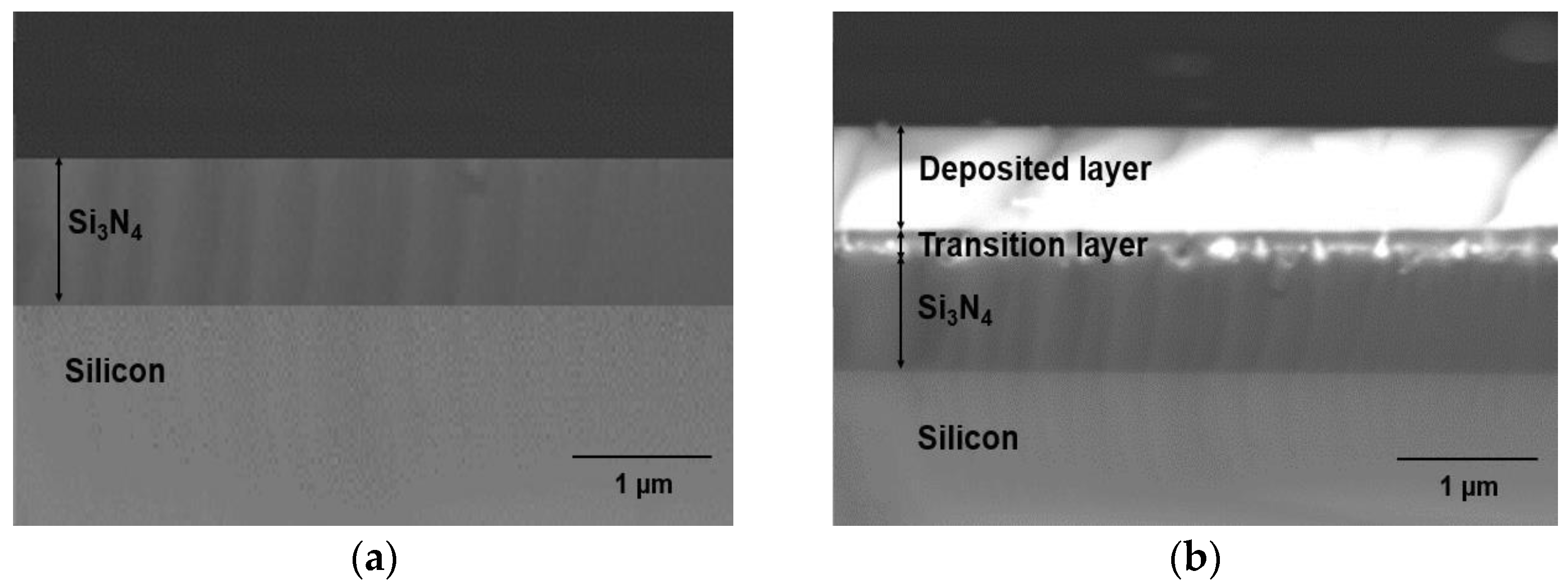
Figure 8a shows a BSE cross-sectional SEM image of a Si3N4-on-silicon substrate prior to ULPD trials, whilst SEM images for samples K470, K520, K570, K600, and K650 are shown in Figure 8b–f. As Figure 8b illustrates, deposition of Er-TZN onto the substrate occurred. The layer formed on the Si3N4 substrate appeared uniform and smooth. However, only a small amount of Er-TZN successfully penetrated Si3N4, indicating that a temperature of 470 °C is not sufficiently high to break the Si-N bond. Only a few of the energetic elements of Er-TZN managed to enter into the Si3N4 molecular network, as could be seen around the materials interface. According to the SEM images in Figure 8c–f, for samples fabricated with a higher temperature of 520–650 °C, Er-TZN successfully diffused into the Si3N4. However, all the images of the doped layer demonstrated that the doping was not as uniform as doping silica with Er-TZN. Although elements from the target material managed to penetrate Si3N4, they were discretely distributed, as depicted by the grayscale variations in the doped layers. This largely inhomogeneous layer appeared to be partly porous, and, in certain areas, an accumulation of specific elements was observed. The SEM images of the surface of the doped layer also showed that it was very uneven and rough, as shown in Figure 9.
The thicknesses of the upper layers for all of the samples are summarised in Table 4. For sample K470, the thickness of the Si3N4 underneath the upper layer was less than the original thickness of 1 μm, which indicated that doping occurred, even though only a small amount was found on the Si3N4 surface. For samples K520, K570, K600, and K650, the upper layer thicknesses could not be precisely determined, and they showed large errors due to their very rough surfaces. However, the estimated thickness obtained showed a linear relationship between thickness and the temperature used to heat the substrate. Additionally, the thickness of the Si3N4 underneath the doped layer became smaller with an increase in substrate temperature. This finding indicated that the material target could react with Si3N4 more thoroughly at higher temperatures. The refractive index and thickness, which were supposedly measured using a prism coupler, could not be measured because of the uneven surface of the doped layer.
Figure 10 shows two different positions in sample K470 measured by EDX-SEM to obtain the elemental concentrations at these particular positions, and the results are shown in Table 5. As the upper layer of sample K470 was only a deposited layer, it was expected to have the properties of tellurite-based glass used as a target material. The high concentration of Te at position 1 confirmed this expectation. For position 2, which is located near the interface of the deposited region and Si3N4 but within the Si3N4, some elements from the target material were mostly oxygen. The smaller atomic size of oxygen than that of Te, Zn, Na, and Er enabled a few energetic ions/atoms of oxygen to successfully penetrate the Si3N4 and oxidise some of it. However, the lower temperatures evidently hindered deeper modification of the Si3N4 layer further. The area scan performed for the sample to determine the distribution of elements in sample K470 is shown in Figure 11. The negligible presence of elements Si and N in the upper layer confirmed that the upper layer consisted of elements from Er-TZN. Besides, the area scan obtained showed an intermediate region between the deposited layer and Si3N4 composed of Si, O, Te, Zn, Na, Er, and N. However, the area scan for Er was less obvious because of its deficient concentration, resulting in considerable noise in the scan results.
An area scan was performed to view the entire elemental distribution present in K600 (Figure 12). The elements were clearly distributed unevenly. Surprisingly, the concentration of N in the doped layer was very low compared with its concentration in Si3N4, which was supposedly around ~57.1 %. Nitrogen was considered lost in the form of nitrogen gas when the tellurite glass reacted with Si3N4, and this phenomenon was also reported by Watanabe et al. [51]. Failure to obtain a very uniform doped layer, such as in the case of EDTS, was probably due to the substrate temperature not being sufficiently high. The melting temperature of Si3N4 (1900 °C) was higher than that of silica (1710 °C). Therefore, higher temperatures may be required to allow the dissolution of Er-TZN into Si3N4 with homogeneous layer formation. Additionally, the failure to obtain homogeneously doped layers may be due to the SiO2 amorphous network, which is somewhat different from Si3N4. Unlike the local structure of silica, which contains adjustable and flexible Si-O-Si- bridging bonds, Si3N4, consists of Si-N-Si bonds that are rendered rigid as N requires bonding with three Si rather than two to form a stable configuration. As a consequence, its network structure is much more constrained than that of silica [52], making it difficult for the elements from Er-TZN to diffuse into Si3N4 and modify it. This leads to the formation of pores and cavities and the accumulation of certain elements for Si3N4 samples. A higher temperature could be expected to help loosen the strong Si-N bonds. Nonetheless, the more rigid Si3N4 structure caused it to have higher internal stress levels and thus to crack more easily. This problem was not observed for samples fabricated using an SOS substrate. Figure 13a,b show the surface images of samples that used different substrates (SiO2 and Si3N4) with the same process parameters and target material. The images were taken under an optical microscope near the edge of the doped layer. The findings clearly showed that the undoped Si3N4 layer on silicon cracked after the sample fabrication process.
Figure 14 shows the XRD patterns of the Si3N4-on-silicon substrate and samples K470, K520, K570, K600, and K650. The patterns showed that all samples were in a mixed amorphous–crystalline phase. The indexed peaks assigned to the possible crystalline structures are also shown in Figure 14. The 2θ peak located at approximately ~69° is a crystalline Si (100) peak originating from the silicon substrate. For sample K470, eleven peaks were detected, namely, 23.38°, 27.87°, 38.63°, 40.61°, 43.61°, 46.42°, 48.73°,49.95°, 57.24°, 63.11°, and 65.98°, which correspond to Te (ICCD reference code: 00-036-1452). The appearance of Te crystallite peaks is attributable to the transition layer between the deposited and Si3N4 layers. For the doped layer of samples K520–K650, the intensity and number of crystalline peaks increased when higher substrate temperatures were used because crystallisation occurs more easily at high temperatures [53,54]. The crystalline peaks for SiO2 (ICCD reference code: 00-039-1425) and Na2Zn3 (SiO4)2 (ICCD reference code: 00-012-3700) started to appear when the sample was heated at 600 °C, and they became more pronounced at higher temperatures. In addition, for the doped layer, the crystalline phase of Te increased in number and intensity with respect to increasing temperature.
Figure 15 presents the Raman spectra for the Si3N4-on-silicon substrate and samples fabricated with various substrate temperatures. The Raman spectra for sample K470 (Figure 15b), comprising tellurite-based glass, were different compared with samples prepared at higher temperatures. As shown in Figure 15c–f, all Raman spectra showed metallic tellurium peaks (122 and 141 cm−1). This finding indicated that the tellurium cluster was likely to form within this doped layer and coincides with the findings from XRD. However, these two peaks were less pronounced in sample K470, suggesting that most of the Te in this sample was present in oxide form rather than metallic form. The stoichiometry of Er-TZN was better preserved in the deposited film than in the doped layer. The Raman spectrum for K470 was similar to that for B400 (Figure 6a) because both of them were deposited tellurite-based layers. The decrease in Si peak intensity from samples K520 to K650 indicated that the thicknesses of the doped layer increased for samples fabricated at higher substrate temperatures. The Raman spectra for samples K520, K570, K600, and K650 (Figure 15c–f) were similar to the EDTS, and only the appearance of peaks at 122 and 141 cm−1 distinguished them. Therefore, the assignment of all other peaks in the spectra was the same as discussed for the EDTS, as the contribution of N was not detectable.
Figure 16 displays the XPS survey spectrum for sample K570. The spectrum pattern obtained resembled that of the EDTS. The absence of N confirmed that N is released when Er-TZN reacts with Si3N4. The distinct peak of N 1s that was expected at a binding energy of around 398 eV was not observed in the obtained spectra. Therefore, N is present only in very small quantities or virtually absent in the doped layer. The presence of Si in the spectral survey verified once again that Er-TZN successfully entered into the Si3N4 layer and formed a predominantly silicate-based layer.
The PL emission spectra for the samples are shown in Figure 17. For K470, the FWHM of the spectra was broader than that of the others, also indicating that the upper layer was a tellurite-based material. The low PL lifetime (4.97 ms) and an FWHM value of approximately 33 nm (Table 6) obtained were comparable with those reported for tellurite glass [24,55]. As shown in Table 6, samples K520, K570, K600, and K650 had a PL lifetime of between 9 and 10 ms and FWHMs of 20 nm. This finding indicated that the doped layer was silicate based, as with the EDTS. If the doped layer is Si3N4 based, it could show a lower lifetime in the range of 0.2–7 ms with an FWHM broader than that of a typical Er-doped silicate-based material [56,57,58]. As shown in Table 6, the higher PL intensity and the lower lifetime of samples prepared at higher substrate temperatures signified that the Er density is higher in the doped layer when the substrate is heated to a higher temperature.

4. Conclusions

In summary, the ULPD technique successfully integrated two immiscible materials (Er-TZN and silica) that resulted in a homogeneous layer of the mixture, referred to as EDTS. However, the quality of the resulting film and the effectiveness of the doping process that occurred were highly dependent on the substrate temperature. The temperature of 400 °C was not sufficient for the incoming plasma plume to modify the strong covalent bonds of silica, and the doping process could not take place. The higher temperature used caused the materials from Er-doped tellurite glass to penetrate more (except Te with smaller concentration) into silica, thus creating a thicker film. The reduced concentration of Te in the doped silica on silicon (SOS) produced at 700 °C caused the refractive index to decline. However, Er-TZN doping into Si3N4 failed to show a homogeneous layer because Si3N4 has a high melting temperature and rigid structure compared with SiO2. A higher temperature could be expected to help loosen the strong Si-N bonds, but the rigid Si3N4 structure caused it to have higher internal stress levels and thus crack more easily.

Author Contributions

Conceptualization, S.A.K. and G.J.; methodology, S.A.K. and G.J.; validation, G.J.; formal analysis, S.A.K.; investigation, S.A.K.; resources, G.J.; data curation, S.A.K.; writing—original draft preparation, S.A.K.; writing—review and editing, S.A.K. and G.J.; visualization, S.A.K.; supervision, G.J.; project administration, S.A.K.; funding acquisition, S.A.K. and G.J. All authors have read and agreed to the published version of the manuscript.

Funding

This work was supported by the Engineering and Physical Sciences Research Council (EPSRC) (EP/M015165/1).

Institutional Review Board Statement

Not applicable.

Informed Consent Statement

Not applicable.

Data Availability Statement

Data are contained within the article.

Acknowledgments

The authors would like to express their gratitude to Thomas Krauss, University of York, the UK, for providing Si3N4-on-silicon substrate. The authors also thank Jose Portoles, National EPSRC XPS Users’ Service (NEXUS), for the support in carrying out the XPS measurements.

Conflicts of Interest

The authors declare no conflict of interest.

References

  1. Vanmathi, P.; Sulthana, A.K.T. Hybrid optical amplifier performance in OAF Using OOK and BPSK modulations. In Proceedings of the International Conference on Intelligent Computing and Control Systems, ICICCS 2019, Secunderabad, India, 15–17 May 2019; pp. 695–699. [Google Scholar] [CrossRef]
  2. Ivanovs, G.; Bobrovs, V.; Olonkins, S.; Alsevska, A.; Gegere, L.; Parts, R.; Gavars, P.; Lauks, G. Application of the erbium-doped fiber amplifier (EDFA) in wavelength division multiplexing (WDM) transmission systems. Int. J. Phys. Sci. 2014, 9, 95–101. [Google Scholar] [CrossRef] [Green Version]
  3. Akcesme, O.; Yucel, M.; Burunkaya, M. The design and implementation of a software based gain control for EDFAs used in long-haul optical networks. Optik 2021, 239, 166850. [Google Scholar] [CrossRef]
  4. Ahad, M.A.; Paul, M.; Muhd-Yassin, S.; Mansoor, A.; Abdul-Rashid, H. Performance Analysis of an EDFA Utilizing a Partially Doped Core Fiber (PDCF). J. Opt. Commun. 2016, 37, 255–259. [Google Scholar] [CrossRef]
  5. Al-Azzawi, A.A.; Almukhtar, A.A.; Reddy, P.H.; Das, S.; Dhar, A.; Paul, M.; Arof, H.; Ahmad, H.; Harun, S.W. An efficient wideband hafnia-bismuth erbium co-doped fiber amplifier with flat-gain over 80 nm wavelength span. Opt. Fiber Technol. 2019, 48, 186–193. [Google Scholar] [CrossRef]
  6. Bradley, J.; Pollnau, M. Erbium-doped integrated waveguide amplifiers and lasers. Laser Photon-Rev. 2010, 5, 368–403. [Google Scholar] [CrossRef]
  7. AHusein, A.H.M.; El-Nahal, F. Optimizing the EDFA gain for WDM lightwave system with temperature dependency. Optik 2012, 123, 586–589. [Google Scholar] [CrossRef]
  8. Afify, N.D.; Dalba, G.; Rocca, F. XRD and EXAFS studies on the structure of Er3+-doped SiO2–HfO2 glass-ceramic waveguides: Er3+-activated HfO2 nanocrystals. J. Phys. D Appl. Phys. 2009, 42, 115416. [Google Scholar] [CrossRef]
  9. Yeatman, E.; Ahmad, M.; McCarthy, O.; Martucci, A.; Guglielmi, M. Sol-Gel Fabrication of Rare-Earth Doped Photonic Components. J. Sol-Gel Sci. Technol. 2000, 19, 231–236. [Google Scholar] [CrossRef]
  10. Chen, Y.; Zhang, M.; Shan, Z.; Wang, C.; Zhang, B.; Xu, J.; Wang, R. High content Er3+-doped 25La2O3-75Ga2O3 glass: A potential material for high-power lasers or EDWA. J. Alloy. Compd. 2020, 837, 155477. [Google Scholar] [CrossRef]
  11. Rönn, J.; Zhang, J.; Zhang, W.; Tu, Z.; Matikainen, A.; Le Roux, X.; Durán-Valdeiglesias, E.; Vulliet, N.; Boeuf, F.; Alonso-Ramos, C.; et al. Erbium-doped hybrid waveguide amplifiers with net optical gain on fully industrial 300 mm silicon nitride photonic platform. Opt. Express 2020, 28, 27919. [Google Scholar] [CrossRef] [PubMed]
  12. Kenyon, A. Recent developments in rare-earth doped materials for optoelectronics. Prog. Quantum Electron. 2002, 26, 225–284. [Google Scholar] [CrossRef]
  13. Kamil, S.A.; Chandrappan, J.; Murray, M.; Steenson, P.; Krauss, T.F.; Jose, G. Ultrafast laser plasma doping of Er3+ ions in silica-on-silicon for optical waveguiding applications. Opt. Lett. 2016, 41, 4684–4687. [Google Scholar] [CrossRef] [PubMed] [Green Version]
  14. Yang, C.; Pham, J. Characteristic Study of Silicon Nitride Films Deposited by LPCVD and PECVD. Silicon 2018, 10, 2561–2567. [Google Scholar] [CrossRef]
  15. Chandrappan, J.; Murray, M.; Kakkar, T.; Petrik, P.; Agocs, E.; Zolnai, Z.; Steenson, D.; Jha, A.; Jose, G. Target dependent femtosecond laser plasma implantation dynamics in enabling silica for high density erbium doping. Sci. Rep. 2015, 5, 14037. [Google Scholar] [CrossRef] [Green Version]
  16. Chandrappan, J.; Murray, M.; Petrik, P.; Agócs, E.; Zolnai, Z.; Tempez, A.; Legendre, S.; Steenson, D.P.; Jha, A.; Jose, G. Doping silica beyond limits with laser plasma for active photonic materials. Opt. Mater. Express 2015, 5, 2849–2861. [Google Scholar] [CrossRef] [Green Version]
  17. Chandrappan, J.; Jose, G.; Murray, M. Implantation of Ions Generated by Laser Ablation. U.S. Patent 2021/0040603 A1, 11 February 2021. [Google Scholar]
  18. Kamil, S.A.; Chandrappan, J.; Portoles, J.; Steenson, P.; Jose, G.; Steenson, D.P. Local structural analysis of erbium-doped tellurite modified silica glass with X-ray photoelectron spectroscopy. Mater. Res. Express 2019, 6, 086220. [Google Scholar] [CrossRef]
  19. Jose, G.; Chandrappan, J.; Kamil, S.A.; Murray, M.; Zolnai, Z.; Agocs, E.; Petrik, P.; Steenson, P.; Krauss, T. Ultrafast laser plasma assisted rare-earth doping for silicon photonics. In Proceedings of the Conference on Lasers and Electro-Optics (CLEO), San Jose, CA, USA, 5–10 June 2016. [Google Scholar]
  20. Chandrappan, J.; Khetan, V.; Ward, M.; Murray, M.; Jose, G. Devitrification of ultrafast laser plasma produced metastable glass layer. Scr. Mater. 2017, 131, 37–41. [Google Scholar] [CrossRef]
  21. Kamil, S.A.; Chandrappan, J.; Krauss, T.F.; Jose, G. Ultrafast laser plasma doping of Er3+ in Si3N4-on-silicon. J. Optoelectron. Adv. Mater. 2019, 21, 710–716. [Google Scholar]
  22. Molatta, S.; Haindl, S.; Trommler, S.; Schulze, M.; Wurmehl, S.; Hühne, R. Interface control by homoepitaxial growth in pulsed laser deposited iron chalcogenide thin films. Sci. Rep. 2015, 5, 16334. [Google Scholar] [CrossRef] [Green Version]
  23. Goldsmid, H.J. Bismuth Telluride and Its Alloys as Materials for Thermoelectric Generation. Materials 2014, 7, 2577–2592. [Google Scholar] [CrossRef] [Green Version]
  24. Vu, K.; Madden, S. Tellurium dioxide Erbium doped planar rib waveguide amplifiers with net gain and 28dB/cm internal gain. Opt. Express 2010, 18, 19192–19200. [Google Scholar] [CrossRef] [PubMed]
  25. Patel, F.; DiCarolis, S.; Lum, P.; Venkatesh, S.; Miller, J. A compact high-performance optical waveguide amplifier. IEEE Photonics Technol. Lett. 2004, 16, 2607–2609. [Google Scholar] [CrossRef]
  26. Irannejad, M.; Jose, G.; Steenson, P.; Jha, A. Enhancement in optical and microstructure properties of Er3+-doped phospho-tellurite glass thin film. Opt. Mater. 2012, 34, 1272–1276. [Google Scholar] [CrossRef]
  27. Polman, A. Erbium implanted thin film photonic materials. J. Appl. Phys. 1997, 82, 1–39. [Google Scholar] [CrossRef]
  28. Snoeks, E.; Kik, P.; Polman, A. Concentration quenching in erbium implanted alkali silicate glasses. Opt. Mater. 1996, 5, 159–167. [Google Scholar] [CrossRef]
  29. Rivera, V.; Chillcce, E.F.; Rodriguez, E.; Cesar, C.; Barbosa, L. Planar waveguides by ion exchange in Er3+-doped tellurite glass. J. Non-Crystalline Solids 2006, 352, 363–367. [Google Scholar] [CrossRef]
  30. Zhao, S.; Wang, X.; Fang, D.; Xu, S.; Hu, L. Spectroscopic properties and thermal stability of Er3+-doped tungsten–tellurite glass for waveguide amplifier application. J. Alloy. Compd. 2006, 424, 243–246. [Google Scholar] [CrossRef]
  31. Boetti, N.G.; Lousteau, J.; Chiasera, A.; Ferrari, M.; Mura, E.; Scarpignato, G.C.; Abrate, S.; Milanese, D. Thermal stability and spectroscopic properties of erbium-doped niobic-tungsten–tellurite glasses for laser and amplifier devices. J. Lumin. 2012, 132, 1265–1269. [Google Scholar] [CrossRef] [Green Version]
  32. Zhang, L.; Dong, G.; Peng, M.; Qiu, J. Comparative investigation on the spectroscopic properties of Pr3+-doped boro-phosphate, boro-germo-silicate and tellurite glasses. Spectrochim. Acta Part A Mol. Biomol. Spectrosc. 2012, 93, 223–227. [Google Scholar] [CrossRef]
  33. Morel, J.; Woodtli, A.; Daniker, R. Characterization of the fluorescent lifetime of doped fibers by measuring the frequency transfer function. J. Light. Technol. 1996, 14, 739–742. [Google Scholar] [CrossRef]
  34. Yang, J.; Dai, S.; Dai, N.; Xu, S.; Wen, L.; Hu, L.; Jiang, Z. Effect of Bi2O3 on the spectroscopic properties of erbium-doped bismuth silicate glasses. J. Opt. Soc. Am. B 2003, 20, 810–815. [Google Scholar] [CrossRef]
  35. de Castro, M.J.; Navarro, J.M.F. Infrared luminescence of erbium-doped sodium lead germanate glass. Appl. Phys. B Lasers Opt. 2012, 106, 669–675. [Google Scholar] [CrossRef]
  36. Luo, W.; Liao, J.; Li, R.; Chen, X. Determination of Judd–Ofelt intensity parameters from the excitation spectra for rare-earth doped luminescent materials. Phys. Chem. Chem. Phys. 2010, 12, 3276–3282. [Google Scholar] [CrossRef]
  37. Bai, X.; Jie, W.; Zha, G.; Zhang, W.; Li, P.; Hua, H.; Fu, L. XPS and SRUPS study of oxygen adsorption on Cd0.9Zn0.1Te (111)A surface. Appl. Surf. Sci. 2009, 255, 7966–7969. [Google Scholar] [CrossRef]
  38. Ogbuu, O.; Du, Q.; Lin, H.; Li, L.; Zou, Y.; Koontz, E.; Smith, C.; Danto, S.; Richardson, K.; Hu, J. Impact of Stoichiometry on Structural and Optical Properties of Sputter Deposited Multicomponent Tellurite Glass Films. J. Am. Ceram. Soc. 2015, 98, 1731–1738. [Google Scholar] [CrossRef]
  39. Seuthe, T.; Grehn, M.; Mermillod-Blondin, A.; Eichler, H.J.; Bonse, J.; Eberstein, M. Structural modifications of binary lithium silicate glasses upon femtosecond laser pulse irradiation probed by micro-Raman spectroscopy. Opt. Mater. Express 2013, 3, 755. [Google Scholar] [CrossRef]
  40. Qiu, W.; Cheng, C.; Zhao, Y.C.; Li, Q. Residual Stress Measurement in Si-based Multilayer Structure by Micro-Raman Spectroscopy. Optics 2015, 4, 33. [Google Scholar] [CrossRef] [Green Version]
  41. Sigaev, V.N.; Lotarev, S.V.; Orlova, E.V.; Golubev, N.V.; Koltashev, V.V.; Plotnichenko, V.G.; Komandin, G.A. Structure of lanthanum-borogermanate glass with stillwellite composition according to vibrational spectroscopy data. Glas. Ceram. 2010, 67, 105–108. [Google Scholar] [CrossRef]
  42. Neuville, D.R.; De Ligny, D.; Henderson, G.S. Advances in raman spectroscopy applied to earth and materials science. In Spectroscopic Methods in Mineralogy and Material Sciences; Henderson, G.S., Neuville, D.R., Eds.; The Mineralogical Society of America: Chantilly, VA, USA, 2015. [Google Scholar]
  43. Ghoshal, S.; Awang, A.; Sahar, M.; Arifin, R. Gold nanoparticles assisted surface enhanced Raman scattering and luminescence of Er3+ doped zinc–sodium tellurite glass. J. Lumin. 2015, 159, 265–273. [Google Scholar] [CrossRef]
  44. Dousti, M.R.; Sahar, M.; Amjad, R.J.; Ghoshal, S.; Awang, A. Surface enhanced Raman scattering and up-conversion emission by silver nanoparticles in erbium–zinc–tellurite glass. J. Lumin. 2013, 143, 368–373. [Google Scholar] [CrossRef]
  45. Sekiya, T.; Mochida, N.; Soejima, A. Raman spectra of binary tellurite glasses containing tri- or tetra-valent cations. J. Non-Crystalline Solids 1995, 191, 115–123. [Google Scholar] [CrossRef]
  46. Robinet, L.; Coupry, C.; Eremin, K.; Hall, C. The use of Raman spectrometry to predict the stability of historic glasses. J. Raman Spectrosc. 2006, 37, 789–797. [Google Scholar] [CrossRef]
  47. Suresh, B.; Zhydachevskii, Y.; Brik, M.; Suchocki, A.; Reddy, M.S.; Piasecki, M.; Veeraiah, N. Amplification of green emission of Ho3+ ions in lead silicate glasses by sensitizing with Bi3+ ions. J. Alloy. Compd. 2016, 683, 114–122. [Google Scholar] [CrossRef]
  48. Bourhis, K.; Shpotyuk, Y.; Massera, J.; Aallos, V.; Jouan, T.; Boussard-Pledel, C.; Bureau, B.; Petit, L.; Koponen, J.; Hupa, L.; et al. Thermal and structural characterization of erbium-doped borosilicate fibers with low silica content containing various amounts of P2O5 and Al2O3. Opt. Mater. 2014, 37, 87–92. [Google Scholar] [CrossRef]
  49. Calahoo, C.M.; Zwanziger, J.W.; Butler, I.S. Mechanical–Structural Investigation of Ion-Exchanged Lithium Silicate Glass using Micro-Raman Spectroscopy. J. Phys. Chem. C 2016, 120, 7213–7232. [Google Scholar] [CrossRef]
  50. McMillan, P. Structural studies of silicate glasses and melts-applications and limitations of Raman spectroscopy. Am. Mineral. 1984, 69, 622–644. [Google Scholar]
  51. Srivastava, M.; Grips, V.W.; Rajam, K. Influence of SiC, Si3N4 and Al2O3 particles on the structure and properties of electrodeposited Ni. Mater. Lett. 2008, 62, 3487–3489. [Google Scholar] [CrossRef]
  52. Dobkin, D.M.; Zuraw, M.K. Principles of Chemical Vapor Deposition: What’s Going on Inside the Reactor; Springer: Dordrecht, The Netherlands, 2003. [Google Scholar]
  53. Zhang, W.; Wu, S.; Chen, X. Effects of substrate temperature and ambient oxygen pressure on growth of Ba(Fe1/2Nb1/2)O3 thin films by pulsed laser deposition. Chin. Sci. Bull. 2013, 58, 3398–3402. [Google Scholar] [CrossRef] [Green Version]
  54. Gupta, V.; Sreenivas, K. Pulsed laser deposition of zinc oxide (ZnO). In Zinc Oxide Bulk, Thin Films and Nanostructures; Jagadish, C., Pearton, S., Eds.; Elsevier: Chennai, India, 2006; pp. 85–174. [Google Scholar]
  55. Chun, Z.; Qin-Yuan, Z.; Yue-Xiao, P.; Zhong-Hong, J. Effects of Nb2O5 on thermal stability and optical properties of Er3+-doped tellurite glasses. Chin. Phys. 2006, 15, 2158–2164. [Google Scholar] [CrossRef]
  56. Polman, A.; Jacobson, D.C.; Eaglesham, D.J.; Kistler, R.C.; Poate, J.M. Optical doping of waveguide materials by MeV Er implantation. J. Appl. Phys. 1991, 70, 3778–3784. [Google Scholar] [CrossRef]
  57. Gong, Y.; Yerci, S.; Li, R.; Negro, L.D.; Vucković, J. Enhanced light emission from erbium doped silicon nitride in plasmonic metal-insulator-metal structures. Opt. Express 2009, 17, 20642–20650. [Google Scholar] [CrossRef] [PubMed] [Green Version]
  58. Olaosebikan, D.; Yerci, S.; Gondarenko, A.; Preston, K.; Li, R.; Negro, L.D.; Lipson, M. Absorption bleaching by stimulated emission in erbium-doped silicon-rich silicon nitride waveguides. Opt. Lett. 2010, 36, 4–6. [Google Scholar] [CrossRef] [PubMed] [Green Version]
Figure 1. Backscattered cross-sectional SEM image of (a) bare SOS substrate and samples doped with Er-TZN when the substrate was heated at (b) 400 °C (B400), (c) 570 °C (B570), and (d) 700 °C (B700).
Nanomaterials 12 00919 g001
Figure 2. XRD patterns for samples prepared using temperatures of (a) 400 °C (B400), (b) 570 °C (B570), and (c) 700 °C (B700).
Nanomaterials 12 00919 g002
Figure 3. PL spectra of upper layer prepared at different substrate temperatures.
Nanomaterials 12 00919 g003
Figure 4. XPS survey scan for samples B400, B570 and B700.
Nanomaterials 12 00919 g004
Figure 5. Te 3d5/2 spectra of the surface of EDTS layer for samples prepared at (a) 400 °C (B400), (b) 570 °C (B570), and (c) 700 °C (B700).
Nanomaterials 12 00919 g005
Figure 6. Raman spectra of samples (a) B400, (b) B570, and (c) B700. B570 and B700 samples show similar spectra.
Nanomaterials 12 00919 g006
Figure 7. Deconvolution of Raman spectra of sample B570 in various Gaussian bands. The bands investigated in this work labelled as A–I are marked.
Nanomaterials 12 00919 g007
Figure 8. BSE cross-sectional SEM images of (a) bare Si3N4-on-silicon substrate, and samples doped with Er-TZN into Si3N4-on-silicon when substrate was heated at (b) 470 °C (K470) (c) 520 °C (K520), (d) 570 °C (K570), (e) 600 °C (K600), and (f) 650 °C (K650).
Nanomaterials 12 00919 g008aNanomaterials 12 00919 g008b
Figure 9. SEM surface morphology of the top surface of the doped layer for sample K600.
Nanomaterials 12 00919 g009
Figure 10. EDX-SEM measurement at two different locations for sample K470. Position 1 is the location where Te is abundant while position 2 is the location near the interface of the deposited region and Si3N4.
Nanomaterials 12 00919 g010
Figure 11. Area scan measured by EDX-SEM for sample K470 with (a) the area being measured. The distribution of species presented is that of (b) silicon, (c) oxygen, (d) tellurium, (e) sodium, (f) zinc, (g) erbium, and (h) nitrogen.
Nanomaterials 12 00919 g011
Figure 12. Area scan measured by EDX-SEM for sample K600 with (a) the area being measured. The distribution of species presented is that of (b) silicon, (c) oxygen, (d) tellurium, (e) sodium, (f) zinc, (g) erbium and (h) nitrogen.
Nanomaterials 12 00919 g012
Figure 13. Surface images taken by optical microscope for samples fabricated with the same process parameters and target material for (a) silica-on-silicon (b) Si3N4-on-silicon substrate.
Nanomaterials 12 00919 g013
Figure 14. XRD patterns of (a) Si3N4-on-silicon substrate and samples (b) K470, (c) K520, (d) K570, (e) K600 and (f) K650.
Nanomaterials 12 00919 g014
Figure 15. Raman spectra of (a) Si3N4-on-silicon substrate and samples (b) K470, (c) K520, (d) K570, (e) K600 and (f) K650.
Nanomaterials 12 00919 g015
Figure 16. XPS survey spectrum for the sample prepared using a substrate temperature of 570 °C (K570).
Nanomaterials 12 00919 g016
Figure 17. Room-temperature PL spectra of samples K470, K520. K570, K600 and K650. The broad shape for sample K470 indicates it has a different host from others.
Nanomaterials 12 00919 g017
Table 1. Variation of the upper layer and remaining silica layer thickness and refractive index prepared at different substrate temperatures.
SampleEDTS Thickness Measured with SEM (µm)EDTS Thickness Measured with Prism Coupler (µm)SiO2 Thickness of the Layer below EDTS Measured with SEM (µm)Refractive Index
B400--1.03 ± 0.03-
B5700.81 ± 0.060.83 ± 0.050.56 ± 0.061.5587 ± 0.0004
B7001.10 ± 0.031.10 ± 0.010.22 ± 0.061.5285 ± 0.0002
Table 2. Percentage of components existing in the upper layer of SOS substrate for samples fabricated using different substrate temperatures obtained from EDX-SEM and XPS.
ElementElemental Concentration (at. %)
B400 (at. %)B570 (at. %)B700 (at. %)
EDX-SEMXPSEDX-SEMXPSEDX-SEMXPS
O50.6952.2461.0158.5160.9158.40
Si1.671.8521.4728.9020.9928.79
Na7.9410.188.575.729.687.08
Zn6.606.956.773.507.144.57
Te32.2127.081.742.890.730.59
Er0.891.700.440.480.550.57
Table 3. FWHM and PL lifetime for film fabricated at different substrate temperatures.
SampleFWHM (nm)PL lifetime (µm)
B400385.26
B5702012.29
B7002011.12
Table 4. The thickness of the upper layer and Si3N4 underneath, as measured by SEM for samples K470, K520, K570, K600, and K650.
SampleThickness (µm)
Upper LayerSi3N4 under Upper Layer
K4701.1 ± 0.10.87 ± 0.04
K5201.5 ± 0.40.74 ± 0.03
K5701.5 ± 0.30.66 ± 0.03
K6001.8 ± 0.30.60 ± 0.05
K6502.0 ± 0.30.57 ± 0.09
Table 5. The elemental concentration of sample K470 at two locations, as shown in Figure 10.
SampleConcentration (µm)
Position 1Position 2
O58.7915.86
Si2.2539.49
Te23.702.83
Zn5.781.23
Na8.451.54
Er0.650.02
N0.3839.03
Table 6. PL lifetime and FWHM of samples K470, K520, K570, K600 and K650.
SampleFWHM (nm)PL Lifetime (µm)
K470334.97
K5202010.43
K570209.94
K600209.71
K650209.59
Publisher’s Note: MDPI stays neutral with regard to jurisdictional claims in published maps and institutional affiliations.

