Article

Preliminary Study on the Preparation of Conductive Nanosized Calcium Carbonate Utilizing Biogas Slurry by a Synchronous Double Decomposition Coating Method

1
College of Mechanical and Energy Engineering, Tongji University, Shanghai 201804, China
2
Modern Agricultural Science & Engineering, Institute of Biomass Energy Research Centre, Tongji University, Shanghai 201804, China
3
School of Ecology and Environment, Anhui Normal University, Wuhu 241000, China
4
Research Center for Environmental Functional Materials, College of Environmental Science and Engineering, Tongji University, Shanghai 200092, China
*
Authors to whom correspondence should be addressed.
Nanomaterials 2023, 13(13), 1938; https://doi.org/10.3390/nano13131938
Submission received: 26 May 2023 / Revised: 20 June 2023 / Accepted: 23 June 2023 / Published: 26 June 2023
(This article belongs to the Special Issue Environmental Restoration Materials and Technologies)

Abstract

:
Nanosized calcium carbonate (NCC) plays a vital role in the rubber and plastic fields as a filler, but it cannot resolve the electrostatic problem. Humic-acid-based NCC (HA-NCC) was accidentally discovered in the reaction between biogas slurry and calcium chloride (CaCl2), based on nutrient recovery and gradient treatment technology to solve the biogas slurry problem. A preliminary study on the preparation of conductive nanosized calcium carbonate (CNCC) from the HA-NCC was implemented. Meanwhile, a synchronous double decomposition coating method was proposed to properly explain the formation of HA-NCC in the biogas slurry. The CNCC was further obtained through drying and carbonizing the HA-NCC sample. The morphology of CNCC was a square shape with aggregation, and its crystals were calcite. The C content of CNCC was 5% higher than that of the normal CaCO3, implying a synchronous coating effect of soluble HA in biogas slurry on NCC. The weight loss of CNCC was about 2.5% at 630 °C, explaining why the HA-NCC remained black at 550 °C for 4 h. The CNCC was partly ordered and graphitized. The resistivity of the CNCC reached 2.62 × 10⁶ Ω·cm. It could be used as a conductive powder. In view of the favorable characteristics described above, CNCC would be expected to be a filler and antistatic agent for plastics and rubbers to enhance the tensile and bending resistance of polymer materials, while eliminating electrostatic hazards. The results are also of great significance for developing high-end products to realize resource utilization of biogas slurry.

1. Introduction

NCC is usually from 10 to 100 nm in size, with a large specific surface area and high surface energy [1,2,3]. It has three basic crystal types: calcite, aragonite, and vaterite [4,5]. Calcite is the most thermodynamically stable anhydrous form [6,7]. The nanometric effects and some special properties of NCC have attracted considerable attention not only as an important building material in organisms, but also as a widely used filler in plastics, rubber, paints, coatings, paper, pharmaceuticals, and agrochemicals [8,9,10]. Importantly, appropriate addition of NCC into plastics and rubbers could enhance the toughness, tensile strength, and thermal stability of the products [11,12,13]. However, plastic or rubber, as a kind of insulator (such as polyvinyl chloride (PVC)) with resistance higher than 1015 Ω [14,15], has the characteristics of triboelectric charge, and the surface charges can be retained for a long time [16], causing static charge accumulation and electrostatic hazards [17,18]. In order to eliminate the electrostatic problems of polymer materials, conductive powder, as an antistatic agent, could be added to plastics or rubbers to decrease their resistivity [19,20]. For instance, graphene/NCC/PVC composite resins were prepared using graphene and NCC as fillers through an in situ polymerization process, to enhance the thermal stability and prevent electrostatic discharge of PVC [21,22,23]. However, the composite resins have found it difficult to overcome the agglomeration of graphene to date.
NCC without conductivity cannot resolve electrostatic issues as a filler of plastic or rubber. If NCC formed a conductive powder via coating of an inorganic or organic conductive material, it would be not only a filler but also an antistatic agent [22,24]. CNCC is a kind of composite nanomaterial with both filler and antistatic functions, which is different from the traditional conductive powders of the metal, metal oxide, and carbon series [21,25]. Compared with the combined addition of NCC and conductive powders to polymer materials [11,22], CNCC could bestow the polymer materials of plastic and rubber with antistatic properties to prevent electrostatic damage. Meanwhile, the excellent performance of NCC itself could enhance the toughness, tensile strength, and thermal stability of plastic or rubber [11,12]. Moreover, CNCC, with its merits of superfine particle size, large amounts, and comfortable interface compatibility, could overcome ordinary antistatic agents with large particle size, long inter-particle distance, and poor dispersion and interface compatibility, leading to poor conductivity, no antistatic effect, reduced safety, and antistatic failure for common antistatic agents [14,20].
A special preparation method has to be taken into consideration to obtain CNCC. It is understood that CNCC is a composite conductive powder coated with inorganic or organic conductive materials using NCC as a substrate via an asynchronous method [26]. The shortcomings of the asynchronous method are its complex process, high cost, and obvious agglomeration, triggering an increase in particle size and affecting the quality and uniformity of the conductive powders. NCC production is synchronized with conductive material coating, which could effectively control the particle size growth of inorganic nanoparticles and avoid aggregation of nanoparticles to resolve the issues of uneven dispersion and easy agglomeration of nanopowders in inorganic/organic composites [27,28]. Shen et al. [29] used sodium carbonate (Na2CO3) and CaCl2 in a mixed solution of polyethylene pyrrolidone (PVP) and sodium dodecylbenzene sulfonate (SDBS) to prepare NCC by the metathesis method and ultimately obtained spherical NCC with adequate dispersion. However, the double decomposition reaction and synchronous coating process relied on expensive chemical reactants, limiting the application of the process for staple products of NCC.
Hence, the cost-effective carbonates and organic coating materials have been the key point for producing CNCC using a simultaneous double decomposition coating method. Industrial biogas slurry was used to produce CNCC by a synchronous double decomposition coating method in this study. A solution of CaCl2 was first added to the biogas slurry to cause the flocculent to precipitate based on bicarbonate stoichiometry. Then, the flocculent precipitate was separated, dried, and carbonized to obtain CNCC. The characteristics of the CNCC were further examined and analyzed. Biogas slurry is the product of anaerobic fermentation of organic waste [30,31]. Due to the use of anaerobic fermentation to achieve the hydrolytic transformation of organic matter, biogas slurry contains high concentrations of ammonia nitrogen, bicarbonate ions, and soluble humic acid. These chemical components of biogas slurry could replace the cost-effective carbonates and organic materials to achieve macroscale preparation of CNCC via the synchronous double decomposition coating method. It is of great significance to implement resource utilization of biogas slurry and develop high-end CNCC products to resolve the electrostatic issues in the plastic and rubber fields.

2. Materials and Methods

2.1. Raw Materials and Chemical Reagents

The wet biogas slurry treated in the experiment was derived from the effluent of the anaerobic fermentation tank at the Miaoji Biogas Station (32°38′7.68″ N, 115°43′3.24″ E), in Funan County, Fuyang City, Anhui Province, China, where it was separated into solid and liquid portions by the mixer. During the test period (1 April 2022 to 14 October 2022), the chemical oxygen demand (COD) of the biogas slurry was 4063~5207 mg/L, the ammoniacal nitrogen (NH4+-N) was 2424~3024 mg/L, and the total alkalinity (in terms of CaCO3) of the bicarbonate ions (HCO3) was 8759~14,264 mg/L. The hardness (in terms of CaCO3) was 70–220 mg/L, the pH was 8.113~8.327, and the water temperature was 14.1~29.4 °C. The methods used to measure COD, NH4+-N, alkalinity, and hardness were as reported in [32].
CaCl2, calcium oxide (CaO), sodium hydroxide (NaOH), Na2CO3, hydrogen peroxide (H2O2), anhydrous ethanol, and hydrochloric acid were used as analytical reagents (ARs) during the test.

2.2. Preparation of CNCC

The wet sample of humic-acid-based nanosized calcium carbonate (HA-NCC) was obtained by a simultaneous double decomposition coating reaction from biogas slurry, CaCl2, and HA. According to the molar alkalinity (HCO3) of 1 L of biogas slurry (0.25 mol/L, 12,513 mg/L) in the lab-scale experiment, the amount of CaCl2 was calculated (see Equation (1)). Due to excess Cl ions, the biogas slurry exhibited acidity. Therefore, the molar ratio between CaCl2 and HCO3 was 0.425. That is, 11.79 g of CaCl2 was dissolved with 17 mL of pure water. CaCl2 solution was added to 1 L of biogas slurry and stirred slowly on a magnetic agitator for 10 min (MS-500, Shanghai, China), followed by static settlement for 20 min. The precipitates of moist HA-NCC were collected through solid–liquid separation. For more detailed preparation of HA-NCC, see reference [32].
Then, the sample of HA-NCC was dried in the oven (DHG-9030A, Shanghai, China) at 105 °C for 12 h to obtain dry HA-NCC. After drying, the dry sample was put into a circular crucible, which was wrapped with tin foil for oxygen isolation. The sample, together with the crucible, was carbonized in a muffle furnace (3X2-4-10H, Shanghai Jing Qi, Shanghai, China) at 550 °C for 4 h. Finally, the carbonized sample was placed in a drying vessel to cool down to room temperature to obtain CNCC as a black powder.

2.3. Characterization Methods

The morphology of black CNCC prepared from biogas slurry was observed by SEM (ZEISS GeminiSEM 300, Jena, Germany). An X-ray diffractometer (XRD) (Rigaku Ultima IV, Takatsuki, Japan) and an X-ray fluorescence spectrograph (XRF) (SHIMADZU XRF-1800, Kyoto, Japan) were used to analyze the phase and elemental compositions of CNCC. The weight changes of CNCC at different temperatures were analyzed by thermogravimetric analysis (TGA) (Mettler STAR, Greifensee, Switzerland). The specific surface area, total pore volume, and pore size of CNCC were determined using a BET instrument (BELSORP MR1, MicrotracBEL, Osaka, Japan). Raman spectrometry (Raman) (Horiba LabRAM HR Evolution, Kyoto, Japan) was used to characterize the structure and properties of CNCC. The CNCC powder was identified by a four-probe instrument (RTS-2, Guangzhou Four Probe Co., Ltd., Guangzhou, China).

3. Results

3.1. HA-NCC Formed in Biogas Slurry

The theory of synchronous metathesis encapsulation states that an organic polymer is mixed with an inorganic precursor in a solvent so that the inorganic precursor chemically synthesizes nanoparticles and fills into the polymer. The existence of polymers can effectively control the growth of inorganic nanoparticles and prevent the agglomeration of nanoparticles.
Biogas slurry is rich in ammonium ions (NH4+), bicarbonate ions (HCO3), and soluble organic matter such as humic acid (HA) [30,31,33]. The content of HA in biogas slurry was measured based on COD concentration. The COD concentration declined from 4018 mg/L to 2649 mg/L. This result indicated that 34% of HA participated in the reaction to produce CaCO3 from biogas slurry [32]. The solution of CaCl2 was put into the biogas slurry to cause a double decomposition reaction, forming a crystal nucleus of calcium carbonate (CaCO3). Due to the enrichment of HA in biogas slurry, it coated the surface of the crystal nucleus of CaCO3. Furthermore, it inhibited the infinite growth of the crystal nucleus and was helpful in controlling the particle size of NCC. It also prevented the agglomeration of particles. The HCO3 of the biogas slurry and CaCl2 solution subjected to the double decomposition reaction to produce CaCO3 is presented in Equation (1). The mechanism of forming HA-NCC from biogas slurry through synchronous double decomposition coating is shown in Figure 1.
C a C l 2 + 2 N H 4 H C O 3 C a C O 3 + C O 2 + 2 N H 4 C l + H 2 O

3.2. Morphological Features of CNCC

Figure 2 shows the morphology of CNCC obtained from HA-NCC through the double decomposition coating reaction of CaCl2 and biogas slurry, after carbonization for 4 h at 550 °C. The reaction of biogas slurry with CaCl2 produced the wet sample of HA-NCC (Figure 2a). The dry HA-NCC after drying at 105 °C for 12 h is displayed in Figure 2b. Figure 2c shows the CNCC sample formed by the carbonization of the dry HA-NCC after oxygen separation at 550 °C for 4 h. According to the SEM observations, the morphology of CNCC showed an encapsulated lamellar shape at 10,000× (Figure 2d), with the agglomeration of irregular and uneven calcite blocks at 50,000× (Figure 2e). This result illustrates that CNCC, with its relatively large particle size, exceeded the nanoscale range with extreme agglomeration (Figure 2d,e). Meanwhile, the NCC was coated by the carbon layer that originated from soluble organic matter, such as HA from biogas slurry (Figure 2d,e). This might be related to the high surface activation energy of CaCO3 and the formation of a carbon skeleton by high-temperature carbonization of soluble organic matter such as HA [34,35]. The results indicate that the CNCC should be further crushed and classified or put into a dispersant to control its particle size within 100 nm [36].

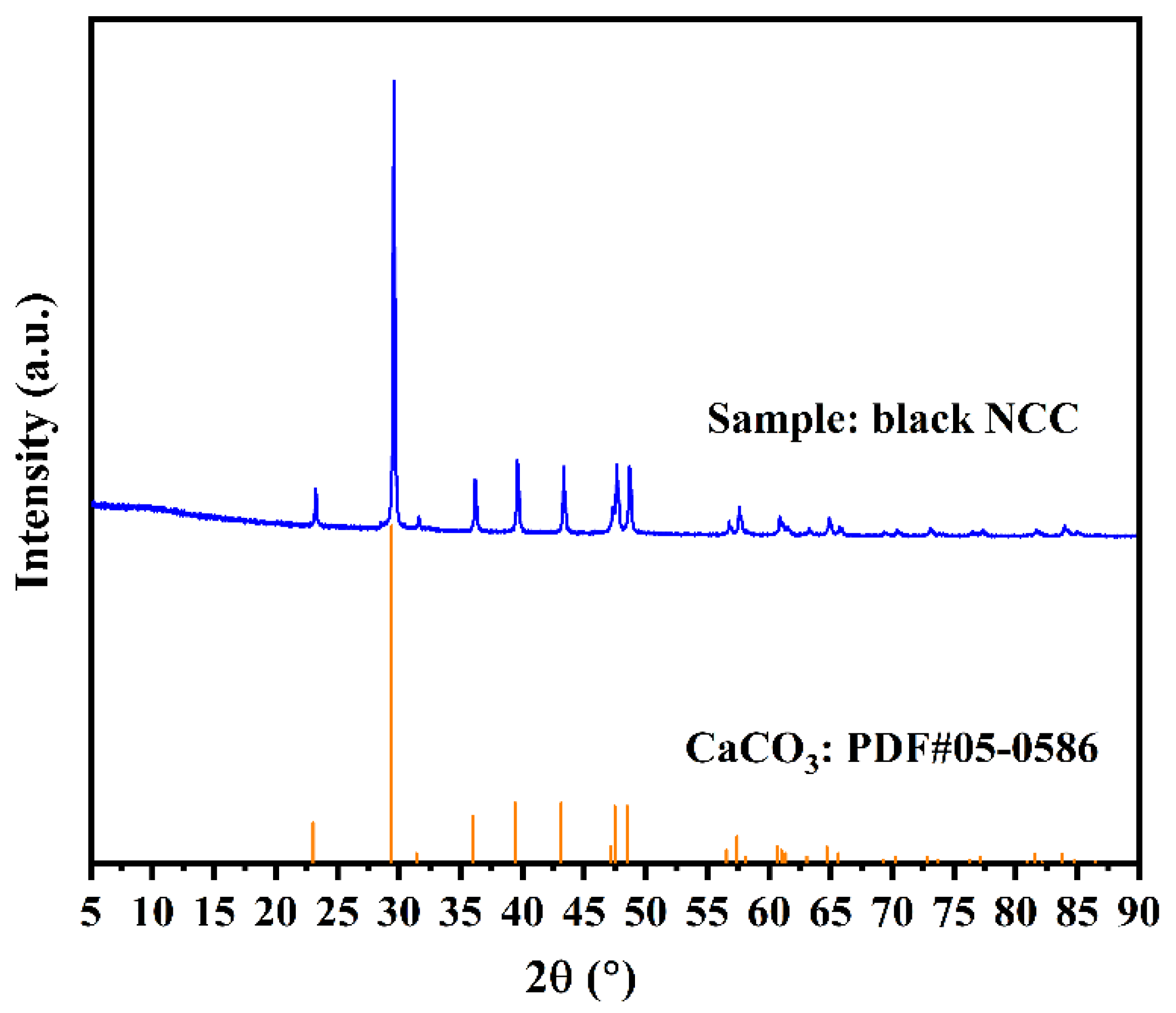
3.3. Crystal Structure and Composition of CNCC
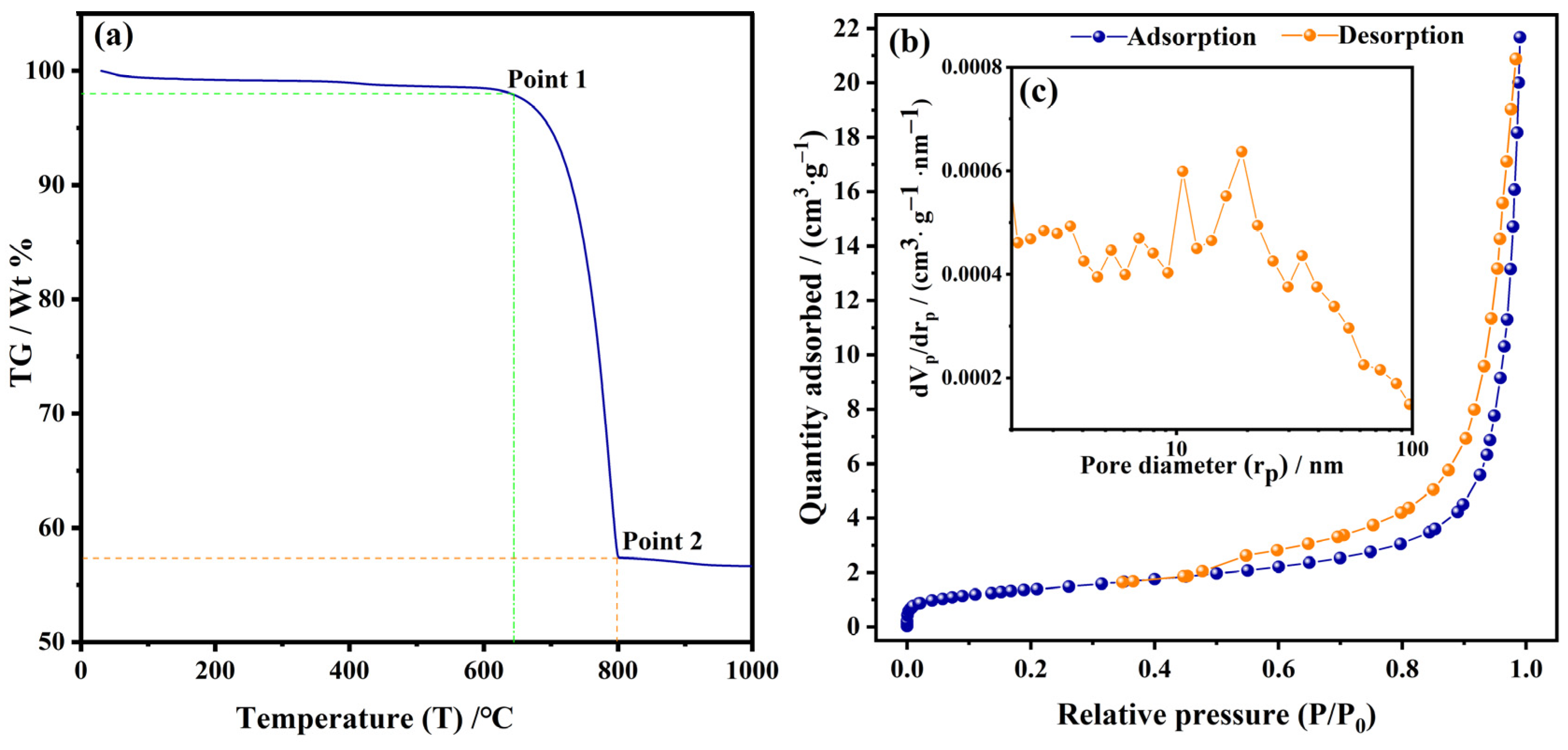
Figure 3 shows the XRD peaks of CNCC. When CaCO3 appeared, the diffraction peaks at 2θ = 23.0°, 29.4°, 36.0°, 39.4°, 43.1°, 47.5°, 48.5°, 56.4°, and 57.5° corresponded to the lattice planes of (012), (104), (110), (113), (202), (018), (116), (211), and (122), respectively. These results indicate that the crystalline form of calcium carbonate was calcite according to the PDF#05-0586 standard, which is consistent with the findings of previous studies [28]. Calcite is more thermodynamically stable than aragonite and vaterite for the crystal structure of CaCO3 [7,37]. The XRF elemental composition analysis of CNCC was performed as shown in Table 1. The results showed that the main elements of CNCC were calcium (Ca), oxygen (O), and carbon (C), further supporting the XRD analysis results. The mass fraction of Ca, O, and C in anhydrous CaCO3 accounted for 40%, 48%, and 12%, respectively. The XRF analysis results indicated that the C content of the CNCC was 5% higher than that the actual CaCO3 content. This part of C might have originated from the coating effect of soluble organic matter such as soluble HA in biogas slurry. Those organic components of biogas slurry—including HA, volatile fatty acids (VFAs), and other biomolecules with chemical characteristics (functional groups)—will be identified and proven in an upcoming study.

3.4. TGA and BET

Figure 4a shows the TGA curve of CNCC. When the temperature rose to approximately 630 °C, the weight loss of the CNCC was about 2.5% (Point 1). This result might be related to the volatilization of the bound water and some part of the organic matter, which explains why the HA-NCC remained black at 550 °C for 4 h. When the temperature was increased to 800 °C, the weight loss of the CNCC was approximately 42.5% (Point 2). This result illustrates that the CNCC was completely decomposed at this high temperature. Its weight loss was about 5% at 700 °C. This might be because the HA coating material was volatilized above 650 °C. The TCA curve of CNCC was a little different from the previous result of the HA-NCC sample in reference [32], and CaCO3 was not completely decomposed below 800 °C [2,38]. Figure 4b shows the N2 adsorption–desorption isotherm of CNCC. With the increase in the relative pressure, the adsorption capacity increased in the curve. When the relative pressure was P/P0 > 0.4, the isotherm showed a hysteresis ring, indicating that the CNCC had mesoporous structure. Figure 4c illustrates the trend of volume distribution with micropores. The BET surface area and total pore volume were 5.03 m2·g−1 and 0.033 cm3·g−1, respectively, and the average pore size was 26.33 nm.

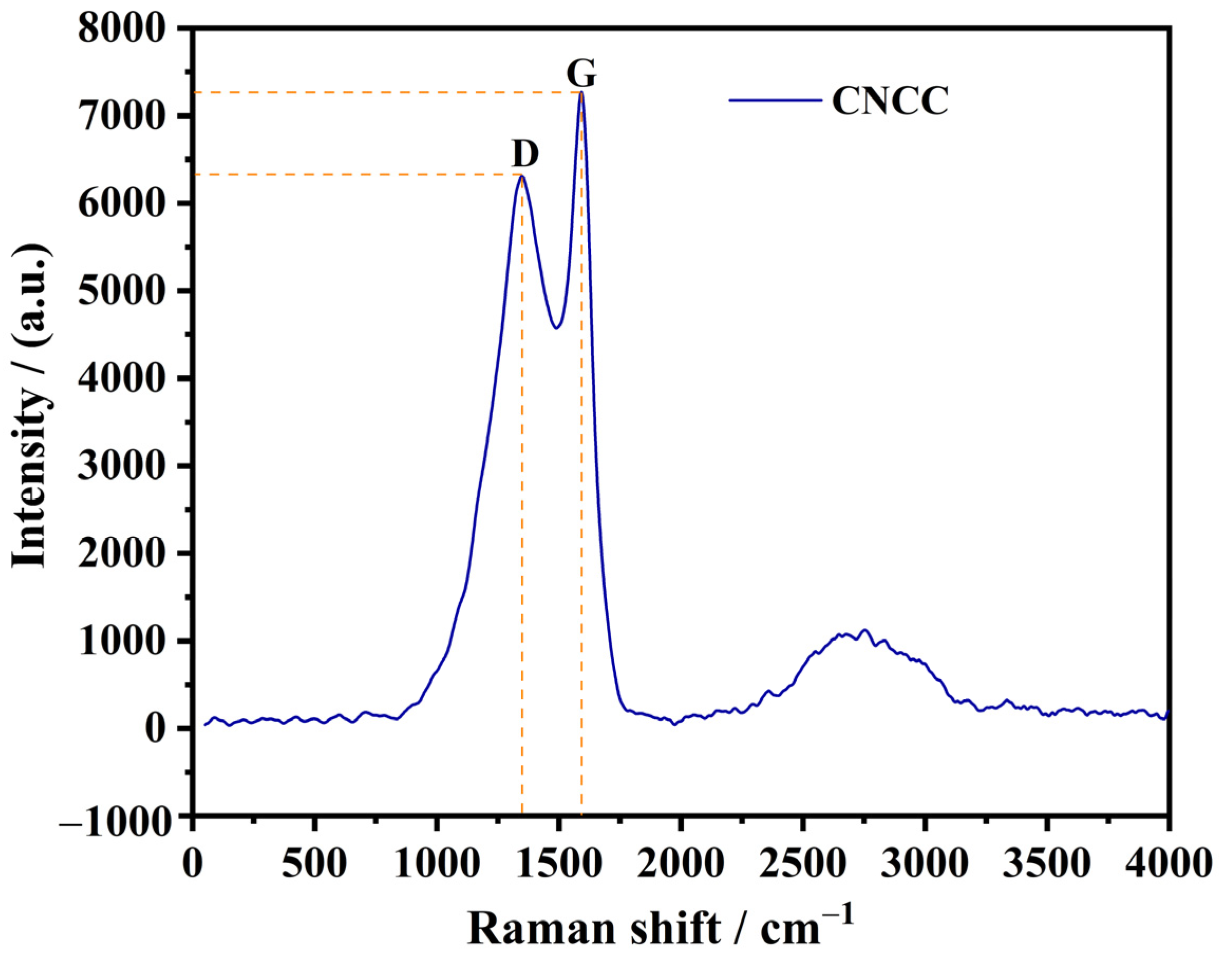
3.5. Graphitization and Conductivity of CNCC

Figure 5 shows the Raman spectra of CNCC. There were two characteristic peaks at 1350 cm−1 and 1590 cm−1, which were attributed to the defect vibration of the carbon atom lattice (peak D) and the expansion vibration of the sp2 carbon atom (peak G), respectively. The intensity ratio of peak D and peak G (ID/IG) represents the degree of graphitization of the carbon materials. The lower the value of ID/IG, the higher the order and integrity of the carbon material, with a stronger graphite structure [23,27]. The results indicated that CNCC had a certain degree of order and graphitization. The resistivity and conductivity results of CNCC, along with the comparative values of other materials, are shown in Table 2. The resistivity and conductivity of CNCC were 2.62 × 10⁶ Ω·cm and 3.8 × 10⁻⁷ S·cm−1, respectively. The resistivity of CNCC was lower than that of CaCO3 and silicon dioxide (SiO2) coated with CaCO3, and higher than that of polyaniline (PANI) and polyaniline silicon dioxide (SiO2-PANI) coated with CaCO3 as a conductive powder. However, the resistivity of CNCC was lower than that of nickel (Ni) coated with CaCO3, under the same mass ratio of CaCO3 and Ni. It has been reported that the resistivity of commercially available antistatic agents and conductive powders ranges from 10−5 to 109 Ω·cm [15]. The resistivity of CNCC was within the required range for conductive powders. This result implies that the black and graphitized CNCC obtained from the heat-treated samples at 550 °C for 4 h has significant potential to improve the electrically conductive properties of rubber as a filler.

4. Discussion

4.1. A Meaningful Discovery in Biogas Slurry

The experiment was designed to use a strong electrolyte (chloride ions (Cl) derived from CaCl2) to replace the weak electrolyte HCO3. The original intention of the experiment was to solve the problem of low conductivity and high energy consumption caused by the weak electrolysis of HCO3, because the weak electrolysis not only affects electrodialysis (ED) for the recovery of ammonium ions (NH4+) and potassium ions (K+), but also accelerates the fouling and scaling of ED due to CaCO3 generation from the chemical reactions between HCO3, OH, and Ca2+ from biogas slurry. The result was an exciting and surprising flocculation precipitation phenomenon, which was designated as HA-NCC by the research team. When the flocculated precipitates were dried and carbonized, they turned black at 550 °C. The physical, chemical, and electrical properties of the CNCC were first investigated. Currently, biogas slurry nutrient recovery and graded gradient treatment engineering, at a full scale of 200 t/d, is carried out in Tianji Biogas Station (32°44′5.46″ N, 115°38′16.67″ E), Funan County, Fuyang City, Anhui Province, China. Here, 4.15~5.24 t/d of HA-NCC was produced through the engineering to solve the weak electrolyte of HCO3 in biogas slurry to mitigate membrane fouling in electrodialysis for nutrient recovery from biogas slurry. In order to achieve the resource utilization of biogas slurry, the macroscale preparation of HA-NCC should be used to develop high-end functional materials such as CNCC, which could be of economic value to balance the cost of biogas slurry treatment.

4.2. Synchronous Double Decomposition Coating Method

The industrial preparation of NCC usually uses carbonization methods. The main limestone was calcined to produce quicklime (Ca(OH)2), and carbon dioxide (CO2) was further carbonized to produce light CaCO3 [4,5]. The influence of Ca(OH)2 concentration, CO2 flow rate, and temperature on the carbonization process [43] caused high industrial production costs, high energy wastage, and high equipment requirements [38]. The double decomposition method to produce CaCO3 was the result of the reaction between the soluble CaCl2 liquid and the soluble carbonate solution [36]. Compared with the carbonization method, the double decomposition method has the virtues of a fast reaction rate and high efficiency. Moreover, it is a liquid–liquid reaction with controllable reaction conditions, and it is easy to study its reaction kinetics law [44].
The NCC was formed by the double decomposition reaction of CaCl2 solution and HCO3 in biogas slurry. Meanwhile, the NCC was coated with dissolved organic matter (DOM) such as HA in the biogas slurry. That is, the HA-NCC in the biogas slurry was formed via the synchronous double decomposition coating method (Figure 1 and Figure 2). The soluble organic matter of HA, with carboxyl, hydroxyl, and other groups, was uniformly dispersed in the biogas slurry [45]. The Ca atoms in the surface molecules of NCC readily chelated with the O atoms in the -OH and -COOH chains of HA [35]. This result was similar to the findings of previous studies on the mechanism of HA regulating the morphology and specific surface area of CaCO3 in the carbonization process [34,35]. More importantly, CaCO3 microcrystals were coated with soluble HA from biogas slurry, with strong molecular binding ability, overcoming the shortcomings of the asynchronous coating method described below.
It is understood that most CNCC composite conductive powders are prepared by using NCC products coated with inorganic or organic conductive materials as a template [39,42,46]. This preparation of CNCC is called the asynchronous method. The asynchronous method has the defects of complex process, high cost, and obvious agglomeration during the coating process, triggering an increase in particle size and affecting the quality and uniformity of the conductive powders [22,40,46]. However, when using the synchronous double decomposition coating method to produce NCC in an inorganic precursor solvent, the polymer coating can effectively control particle size growth of inorganic nanoparticles and avoid aggregation of nanoparticles, resolving the issues of uneven dispersion in inorganic/organic composites [27,29]. For instance, potassium humate 3D graphene was prepared by adding soluble additives to prevent potassium humate agglomeration [27]. Spherical NCC with a good dispersion was obtained by the reaction of Na2CO3 and CaCl2 in the mixed aqueous solution of polyethylene pyrrolidone (PVP) and sodium dodecylbenzene sulfonate [29]. It is worth noting that the use of cheap carbonates and organic materials has been a vital point in the macroscale preparation of CNCC using the double decomposition coating method. A great deal of CNCC could be prepared by the double decomposition coating method in biogas slurry. It is of great significance to realize the resource utilization of biogas slurry and develop high-end green products.

4.3. CNCC

Recently, researchers have been interested in the production of composite conductive powders from NCC and organic materials, because organic conductive materials have stronger corrosion resistance and lower cost than inorganic metal materials when used as coating materials for NCC. Commonly used polymer materials include polyaniline (PANI), polypyrrole (PPy), polyacetylene (PA), and polythiophene (PTi) [22,40]. Among them, PANI has excellent conductivity, antisepsis, and non-toxicity [40]. The conductive powder prepared by PANI coated with NCC not only had good conductivity but also enhanced the thermal stability, mechanical strength, and adhesion of the conductive powder, through synergistic action with NCC.
This study is the first to report the preparation of CNCC from the HA-NCC via synchronous double decomposition coating in biogas slurry, with a resistivity of 2.62 × 10⁶ Ω·cm, adhering to the resistivity requirements of conductive powders (10−5~109 Ω·cm) [15,22]. However, it is important to emphasize that the CNCC in this study should be further optimized to reduce its resistivity compared to the other conductive powders listed in Table 2. In summary, CNCC as a filler and antistatic agent could improve the structural function of polymer materials such as plastic and rubber, while also resolving the electrostatic problem. The conductivity of CNCC should be further investigated in upcoming research when CNCC is added to rubber or plastic as a filler.

4.4. Limitations and Development Prospects

The CNCC derived from HA-NCC by the synchronous double decomposition coating method, using biogas slurry as a raw material, was used to develop high-end and functional products conforming to market requirements. For one thing, the biogas slurry needed no longer be regarded as sewage and achieved the goal of resource utilization. For another, the formed CNCC powder, as a filler and antistatic agent, improved the structural properties of polymer materials such as plastic and rubber, while also resolving the electrostatic problem. This would be beneficial for the green and high-quality development of enterprises. However, this was only a preliminary study aiming at the preparation of CNCC from the perspective of biogas slurry resource utilization. The CNCC particle size was still large, with a significant agglomeration phenomenon. Future work concerning CNCC should be carried out with regard to the tunable conditions of particle size, specific surface area, and microstructure, as well as electrochemical performance optimization to decrease its particle size, enhance its specific surface area, and improve its conductivity.

5. Conclusions

Based on biogas slurry obtained from anaerobic fermentation in a biogas station, using nutrient recovery and graded gradient treatment technology, the use of a strong Cl electrolyte from CaCl2 solution to replace the weak HCO3 electrolyte in biogas slurry was investigated. The flocculent precipitates of HA-NCC were discovered unexpectedly, by the reaction of CaCl2 and biogas slurry. According to the discovery, the double decomposition coating method was proposed to prepare the HA-NCC. Then, the preparation of CNCC was further preliminarily explored by the HA-NCC. The morphology, structure, composition, specific surface area, and resistivity of the CNCC were also examined primitively. The morphology of CNCC exhibited aggregation consisting of an ample cuboidal matrix. CNCC showed a calcite crystal structure, and its C mass fraction was 5% higher than the C mass fraction of actual CaCO3, revealing the coating effect of HA in biogas slurry on the NCC. The TGA results reveal why HA-NCC showed a black color after treatment at 550 °C for 4 h. About 5% of its weight at 700 °C was lost, resulting from the coated C being volatilized in gas form at that temperature. The CNCC had a specific surface area of 5.03 m2·g−1, total pore volume of 0.033 cm3·g−1, and average pore size of 26.33 nm, as well as mesoporous properties. The sample was graphitized to an extensive degree. The resistivity of the sample was 2.62 × 10⁶ Ω·cm, implying its conductivity. The CNCC showed the potential to develop a conductive powder. It would be expected to be used as a filler in the plastics and rubber industries, and as an antistatic agent to eliminate electrostatic hazards.

Author Contributions

F.P. designed the experiments and drafted the manuscript. H.X. and F.H. carried out all experiments of CNCC preparation and related work. J.L. helped to characterize the CNCC sample, analyzed the characterized data, and edited the manuscript. H.Z. and J.M. designed the manuscript. All authors have read and agreed to the published version of the manuscript.

Funding

This research was funded by “National Key R&D Program of China” (Grant No. 2018YFC1903204). This work was supported by Shanghai Linhai Ecological Technology Co., LTD. and Funan Linhai Ecological Technology Co., LTD.

Data Availability Statement

Where no new data were created.

Acknowledgments

We would like to thank Yinli-Zhang, Hongfeng-Hu, Jianlin-Zhao, and Xin-Zhang from Shanghai Linhai Ecological Technology Corp. for in situ sample collection.

Conflicts of Interest

The authors declare no conflict of interest.

References

  1. Nooririnah, A.; Azwar, M.A.; Yusliza, Y.; Abreeza, M.; Ashadi, M.J. Effect of CO2 Flow Rate on the Synthesis Nanosized Precipitated Calcium Carbonate, PCC. Appl. Mech. Mater. 2014, 481, 72–75. [Google Scholar] [CrossRef]
  2. Wu, G.; Wang, Y.; Zhu, S.; Wang, J. Preparation of ultrafine calcium carbonate particles with micropore dispersion method. Powder Technol. 2007, 172, 82–88. [Google Scholar] [CrossRef]
  3. Ding, J.; Ma, W.; Song, F.; Zhong, Q. Effect of nano-Calcium Carbonate on microcellular foaming of polypropylene. J. Mater. Sci. 2013, 48, 2504–2511. [Google Scholar] [CrossRef]
  4. Ramakrishna, C.; Thenepalli, T.; Ahn, J.W. A Brief review of Aragonite Precipitated Calcium Carbonate (PCC) Synthesis Methods and Its Applications. Korean Chem. Eng. Res. 2017, 55, 443–455. [Google Scholar]
  5. Ramakrishna, C.; Thenepalli, T.; Ahn, J.W. Evaluation of Various Synthesis Methods for Calcite-Precipitated Calcium Carbonate (PCC) Formation. Korean Chem. Eng. Res. 2017, 55, 279–286. [Google Scholar]
  6. McDonald, L.J.; Afzal, W.; Glasser, F.P. Evidence of scawtite and tilleyite formation at ambient conditions in hydrated Portland cement blended with freshly-precipitated nano-size calcium carbonate to reduce greenhouse gas emissions. J. Build. Eng. 2022, 48, 103906. [Google Scholar] [CrossRef]
  7. Polat, S. Evaluation of the effects of sodium laurate on calcium carbonate precipitation: Characterization and optimization studies. J. Cryst. Growth 2019, 508, 8–18. [Google Scholar] [CrossRef]
  8. Melotti, R.; Santagata, E.; Bassani, M.; Salvo, M.; Rizzo, S. A preliminary investigation into the physical and chemical properties of biomass ashes used as aggregate fillers for bituminous mixtures. Waste Manag. 2013, 33, 1906–1917. [Google Scholar] [CrossRef]
  9. Swain, S.K.; Dash, S.; Kisku, S.K.; Singh, R.K. Thermal and Oxygen Barrier Properties of Chitosan Bionanocomposites by Reinforcement of Calcium Carbonate Nanopowder. J. Mater. Sci. Technol. 2014, 30, 791–795. [Google Scholar] [CrossRef]
  10. Kim, M.K.; Lee, J.A.; Jo, M.R.; Kim, M.K.; Kim, H.M.; Oh, J.M.; Song, N.W.; Choi, S.J. Cytotoxicity, Uptake Behaviors, and Oral Absorption of Food Grade Calcium Carbonate Nanomaterials. Nanomaterials 2015, 5, 1938–1954. [Google Scholar] [CrossRef] [Green Version]
  11. Andricic, B.; Kovacic, T.; Klaric, I. Properties of recycled material containing poly(vinyl chloride), polypropylene, and calcium carbonate nanofiller. Polym. Eng. Sci. 2008, 48, 572–577. [Google Scholar] [CrossRef]
  12. Ari, G.A.; Aydin, I. Nanocomposites prepared by solution blending: Microstructure and mechanical properties. J. Macromol. Sci. B 2008, 47, 260–267. [Google Scholar]
  13. Liang, J.Z.; Tang, C.Y.; Zhou, L.; Tsui, C.P.; Li, F.J. Melt flow behavior in capillary extrusion of nanosized calcium carbonate-filled poly(L-lactic acid) biocomposites. Polym. Eng. Sci. 2012, 52, 1839–1844. [Google Scholar] [CrossRef]
  14. Bao, L.; Lei, J.; Wang, J. Preparation and characterization of a novel antistatic poly(vinyl chloride)/quaternary ammonium based ion-conductive acrylate copolymer composites. J. Electrostat. 2013, 71, 987–993. [Google Scholar] [CrossRef]
  15. Kuo, Y.C.; Lee, C.H.; Rajesh, R. Iron oxide-entrapped solid lipid nanoparticles and poly(lactide-co-glycolide) nanoparticles with surfactant stabilization for antistatic application. J. Mater. Res. Technol. 2019, 8, 887–895. [Google Scholar] [CrossRef]
  16. Li, J.; Wu, G.; Xu, Z. Tribo-charging properties of waste plastic granules in process of tribo-electrostatic separation. Waste Manag. 2015, 35, 36–41. [Google Scholar] [CrossRef]
  17. Zhang, J.; Ciampi, S. The Position of Solid Carbon Dioxide in the Triboelectric Series. Aust. J. Chem. 2019, 72, 633–636. [Google Scholar] [CrossRef] [Green Version]
  18. Wang, J.; Che, R.; Yang, W.; Lei, J. Biodegradable antistatic plasticizer based on citrate electrolyte doped with alkali metal salt and its poly(vinyl chloride) composites. Polym. Int. 2011, 60, 344–352. [Google Scholar] [CrossRef]
  19. Jenbanphue, T.; Hongesombut, K.; Jitkajornwanich, K.; Srisonphan, S. Electrostatic Properties and Ions Elimination Effect of Polyvinyl Chloride (PVC) Adhesive Tape Manufacturing. In Proceedings of the 2020 8th International Electrical Engineering Congress (IEECON), Chiang Mai, Thailand, 4–6 March 2020; pp. 1–4. [Google Scholar]
  20. Almeida, S.; Ozkan, S.; Goncalves, D.; Paulo, I.; Queiros, C.; Ferreira, O.; Bordado, J.; dos Santos, R.G. A Brief Evaluation of Antioxidants, Antistatics, and Plasticizers Additives from Natural Sources for Polymers Formulation. Polymers 2023, 15, 6. [Google Scholar] [CrossRef]
  21. Yang, P.; Yu, F.; Yang, Z.; Zhang, X.; Ma, J. Graphene oxide modified κ-carrageenan/sodium alginate double-network hydrogel for effective adsorption of antibiotics in a batch and fixed-bed column system. Sic. Total Environ. 2022, 837, 155662. [Google Scholar] [CrossRef]
  22. de Souza Vieira, L.; dos Anjos, E.G.R.; Verginio, G.E.A.; Oyama, I.C.; Braga, N.F.; da Silva, T.F.; Montagna, L.S.; Rezende, M.C.; Passador, F.R. Carbon-based materials as antistatic agents for the production of antistatic packaging: A review. J. Mater. Sci.-Mater. El. 2021, 32, 3929–3947. [Google Scholar] [CrossRef]
  23. Ma, J.; Sun, Y.; Zhang, M.; Yang, M.; Gong, X.; Yu, F.; Zheng, J. Comparative Study of Graphene Hydrogels and Aerogels Reveals the Important Role of Buried Water in Pollutant Adsorption. Environ. Sci. Technol. 2017, 51, 12283–12292. [Google Scholar] [CrossRef]
  24. Jyoti, J.; Kumar, A.; Dhakate, S.R.; Singh, B.P. Dielectric and impedance properties of three dimension graphene oxide carbon nanotube acrylonitrile butadiene styrene hybrid composites. Polym. Test. 2018, 68, 456–466. [Google Scholar] [CrossRef]
  25. Zhou, Z.; Yu, F.; Ma, J. Nanoconfinement engineering for enchanced adsorption of carbon materials, metal-organic frameworks, mesoporous silica, MXenes and porous organic polymers: A review. Environ. Chem. Lett. 2022, 20, 563–595. [Google Scholar] [CrossRef]
  26. Chathuranga Senarathna, K.G.; Mantilaka, M.M.M.G.P.G.; Nirmal Peiris, T.A.; Pitawala, H.M.T.G.A.; Karunaratne, D.G.G.P.; Rajapakse, R.M.G. Convenient routes to synthesize uncommon vaterite nanoparticles and the nanocomposites of alkyd resin/polyanifine/vaterite: The latter possessing superior anticorrosive performance on mild steel surfaces. Electrochim. Acta 2014, 117, 460–469. [Google Scholar] [CrossRef]
  27. Huang, G.; Liu, Q.; Kang, W.; Xing, B.; Chen, L.; Zhang, C. Potassium humate based reduced graphite oxide materials for supercapacitor applications. Electrochim. Acta 2016, 196, 450–456. [Google Scholar] [CrossRef]
  28. Barhoum, A.; Van Lokeren, L.; Rahier, H.; Dufresne, A.; Van Assche, G. Roles of in situ surface modification in controlling the growth and crystallization of CaCO3 nanoparticles, and their dispersion in polymeric materials. J. Mater. Sci. 2015, 50, 7908–7918. [Google Scholar] [CrossRef]
  29. Shen, Q.; Wei, H.; Zhao, Y.; Wang, D.J.; Zheng, L.Q.; Xu, D.F. Morphological control of calcium carbonate crystals by polyvinylpyrrolidone and sodium dodecyl benzene sulfonate. Colloid. Surface. A 2004, 251, 87–91. [Google Scholar] [CrossRef]
  30. Liu, X.Y.; Zhu, H.G. Treatment of Low C/N Ratio Wastewater by a Carbon Cloth Bipolar Plate Multicompartment Electroenhanced Bioreactor (CBM-EEB). ACS Omega 2020, 5, 27823–27832. [Google Scholar] [CrossRef]
  31. Hu, Z.H.; Zhu, H.G. Effects of Combined Technologies on Environmental Prevention against Livestock Pollution in Biogas Projects. J. Environ. Eng. 2019, 145, 1–7. [Google Scholar] [CrossRef]
  32. Pan, F.H.; Xiao, H.; Huang, F.; Lei, J.J.; Zhu, H.G.; Ma, J. Macroscale preparation nanosized calcium carbonate exploiting biogas slurry synchronous metathesis encapsulation method. New J. Chem. 2023. [Google Scholar] [CrossRef]
  33. Gu, L.P.; Tang, X.; Sun, Y.; Kou, H.J. Bioavailability of dissolved organic matter in biogas slurry enhanced by catalytic ozonation combined with membrane separation. Ecotoxicol. Environ. Saf. 2020, 196, 110547. [Google Scholar] [CrossRef]
  34. Falini, G.; Fermani, S.; Tosi, G.; Dinelli, E. Calcium Carbonate Morphology and Structure in the Presence of Seawater Ions and Humic Acids. Crys. Growth Des. 2009, 9, 2065–2072. [Google Scholar] [CrossRef]
  35. Chen, M.; Gowthaman, S.; Nakashima, K.; Kawasaki, S. Influence of humic acid on microbial induced carbonate precipitation for organic soil improvement. Environ. Sci. Pollut. R 2023, 30, 15230–15240. [Google Scholar] [CrossRef]
  36. Neira-Carrillo, A.; Vasquez-Quitral, P.; Sanchez, M.; Farhadi-Khouzani, M.; Aguilar-Bolados, H.; Yazdani-Pedram, M.; Colfen, H. Functionalized Multiwalled CNTs in Classical and Nonclassical CaCO3 Crystallization. Nanomaterials 2019, 9, 1169. [Google Scholar] [CrossRef] [Green Version]
  37. Wang, J.; Song, J.; Ji, Z.; Liu, J.; Guo, X.; Zhao, Y.; Yuan, J. The preparation of calcium carbonate with different morphologies under the effect of alkanolamide. Colloid. Surface. A 2020, 588, 124392. [Google Scholar] [CrossRef]
  38. Cizer, O.; Rodriguez-Navarro, C.; Ruiz-Agudo, E.; Elsen, R.J.; Van Gemert, D.; Van Balen, K. Phase and morphology evolution of calcium carbonate precipitated by carbonation of hydrated lime. J. Mater. Sci. 2012, 47, 6151–6165. [Google Scholar] [CrossRef] [Green Version]
  39. Hai, J.; Yang, J.X.; Cheng, J.; Yang, Z.R. Preparation and Performance of RTV Coating for Anti-pollution Flashover with Superhydrophobicity by Filling CaCO3/SiO2 Composite Particles into Silicone Rubber. Adv. Mater. Res. 2011, 328, 1263–1267. [Google Scholar] [CrossRef]
  40. Zhu, A.; Wang, H.; Sun, S.; Zhang, C. The synthesis and antistatic, anticorrosive properties of polyaniline composite coating. Prog. Org. Coat. 2018, 122, 270–279. [Google Scholar] [CrossRef]
  41. Zhang, Y.; Chu, W.; Zhou, Q.; Li, S.; Li, N.; Zheng, J. Electrochemical behaviors of polyaniline confined in highly ordered micro-sized SiO2 cavities. Electroanal. Chem. 2016, 775, 105–109. [Google Scholar] [CrossRef]
  42. Kim, K.N.; Kim, Y.D. Synthesis of Calcium Carbonate Particles Modified by Coating with Nickel Precursor. Mater. Sci. Forum 2005, 486, 546–549. [Google Scholar] [CrossRef]
  43. Huang, G.; Kang, W.; Xing, B.; Chen, L.; Zhang, C. Oxygen-rich and hierarchical porous carbons prepared from coal based humic acid for supercapacitor electrodes. Fuel Process. Technol. 2016, 142, 1–5. [Google Scholar] [CrossRef]
  44. Jimoh, O.A.; Ariffin, K.S.; Bin Hussin, H.; Temitope, A.E. Synthesis of precipitated calcium carbonate: A review. Carbonates Evaporites 2018, 33, 331–346. [Google Scholar] [CrossRef]
  45. Lan, T.; Wu, P.; Liu, Z.; Stroet, M.; Liao, J.; Chai, Z.; Mark, A.E.; Liu, N.; Wang, D. Understanding the Effect of pH on the Solubility and Aggregation Extent of Humic Acid in Solution by Combining Simulation and the Experiment. Environ. Sci. Technol. 2022, 56, 917–927. [Google Scholar] [CrossRef]
  46. Costa, V.L.D.; Simoes, R.M.S. Hydrophobicity improvement of cellulose nanofibrils films by stearic acid and modified precipitated calcium carbonate coating. J. Mater. Sci. 2022, 57, 11443–11459. [Google Scholar] [CrossRef]
Figure 1. Preparation of humic-acid-based nanosized calcium carbonate (HA-NCC) from biogas slurry by a simultaneous double decomposition coating method.
Nanomaterials 13 01938 g001
Figure 2. Optical photographs of wet HA-NCC prepared in biogas slurry (a), dry HA-NCC (105 °C, 12 h) (b), and CNCC heated at 550 °C for 4 h (c). SEM images of CNCC at 10,000× magnification (d) and 50,000× magnification (e).
Nanomaterials 13 01938 g002
Figure 3. XRD results of CNCC at 550 °C for 4 h.
Nanomaterials 13 01938 g003
Figure 4. TGA curve (a) and N2 adsorption–desorption isotherm curve (b,c) of CNCC.
Nanomaterials 13 01938 g004
Figure 5. Raman spectra of CNCC. Peak D represents the defect vibration of the carbon atom lattice and peak G signifies the expansion vibration of the sp2 carbon atom.
Nanomaterials 13 01938 g005
Table 1. XRF analysis results of CNCC (550 °C, 4 h).
Chemical ElementMass Percentage of Chemical Element (%)Oxide ComponentMass Percentage of Oxide Component (%)
Ca57.45CaO50.35
O22.01CO247.09
C17.97P2O50.95
Cl0.84Cl0.61
P0.56K2O0.29
Sr0.36SrO0.21
K0.34SO30.15
Na0.12Na2O0.12
Zn0.12ZnO0.07
Fe0.09SiO20.07
S0.08Fe2O30.06
Si0.04Al2O30.03
Al0.02--
Total100.00Total100.00
Table 2. Resistivity and conductivity of CNCC compared with other materials.
Functional MaterialsResistivity/Ω·cmConductivity/S·cm−1References
CNCC2.62 × 1063.8 × 10−7This study
CaCO3>107<10−7[39]
CaCO3-SiO2>107<10−7[39]
Polymers1015~101710−15~10−17[15]
Pure polyaniline (PANI)2.63 × 1023.8 × 10−1[40]
CaCO3-SiO2-PANI (1:1~3:1)1.79 × 10³~1.75 × 1045.6 × 10−2~5.7 × 10⁻³[41]
PANI/CaCO3 composites1.0 × 1051.0 × 10−5[26]
CaCO3-Ni (0.47:1~1:1)1.2 × 10⁶~3.4 × 10118.3 × 10−7~2.9 × 10⁻¹²[42]
Disclaimer/Publisher’s Note: The statements, opinions and data contained in all publications are solely those of the individual author(s) and contributor(s) and not of MDPI and/or the editor(s). MDPI and/or the editor(s) disclaim responsibility for any injury to people or property resulting from any ideas, methods, instructions or products referred to in the content.

