Article

Construction of Carbon Nanofiber-Wrapped SnO2 Hollow Nanospheres as Flexible Integrated Anode for Half/Full Li-Ion Batteries

1
School of Electrical and Information, Jilin Engineering Normal University, Changchun 130052, China
2
School of Materials Science and Engineering, Changchun University of Science and Technology, Changchun 130022, China
3
School of Metallurgy, Northeastern University, Shenyang 110819, China
*
Author to whom correspondence should be addressed.
Nanomaterials 2023, 13(15), 2226; https://doi.org/10.3390/nano13152226
Submission received: 3 July 2023 / Revised: 27 July 2023 / Accepted: 28 July 2023 / Published: 31 July 2023
(This article belongs to the Section Energy and Catalysis)

Abstract

:
SnO2 is deemed a potential candidate for high energy density (1494 mAh g−1) anode materials for Li-ion batteries (LIBs). However, its severe volume variation and low intrinsic electrical conductivity result in poor long-term stability and reversibility, limiting the further development of such materials. Therefore, we propose a novel strategy, that is, to prepare SnO2 hollow nanospheres (SnO2-HNPs) by a template method, and then introduce these SnO2-HNPs into one-dimensional (1D) carbon nanofibers (CNFs) uniformly via electrospinning technology. Such a sugar gourd-like construction effectively addresses the limitations of traditional SnO2 during the charging and discharging processes of LIBs. As a result, the optimized product (denoted SnO2-HNP/CNF), a binder-free integrated electrode for half and full LIBs, displays superior electrochemical performance as an anode material, including high reversible capacity (~735.1 mAh g−1 for half LIBs and ~455.3 mAh g−1 at 0.1 A g−1 for full LIBs) and favorable long-term cycling stability. This work confirms that sugar gourd-like SnO2-HNP/CNF flexible integrated electrodes prepared with this novel strategy can effectively improve battery performance, providing infinite possibilities for the design and development of flexible wearable battery equipment.

1. Introduction

By virtue of their high energy density, long life span, and low environmental impact, Li-ion batteries (LIBs) are considered the predominant power source for many electronic applications, including portable devices, electric vehicles, and even future flexible wearable devices [1,2,3,4,5]. To meet the ever-growing market demands of high-energy LIBs, it is necessary to develop advanced anode materials to replace conventional graphite anode materials, which have a low specific capacity of 372 mAh g−1 and restricted energy density [6]. Therefore, there is a pressing need to develop a novel anode material to replace the traditional graphite.
In recent years, much attention has been paid to the search for alternative anodes with high reversible capacity. Among various MOx-based anode materials, tin dioxide (SnO2) stands out and has been followed with interest in the field of LIBs due to its high specific capacity (1494 mAh g−1), proper operating voltage, abundant resources, and low toxicity [7,8,9]. However, due to the severe volume expansion (over 300%) during the reciprocating motion of Li+, the electrode is severely crushed and the capacity is severely reduced, making the practical utility of SnO2 a major obstacle [10]. The low intrinsic electrical conductivity of this material will also result in a relatively inferior rate capacity in charging–discharging cycles [11,12]. As a result, the development of high-performance SnO2 anode materials has become essential for exploring next-generation LIBs.
Currently, many effective approaches have been proposed to address the aforementioned issues. For instance, it has been proposed SnO2 materials be synthesized at the nanoscale to effectively minimize volume-change stress and shorten the migration distance of Li+. Thus, considerable effort has been invested in the synthesis of nanoscale SnO2 with various morphologies, such as nanoparticles [13,14], nanotubes [15,16], nanorods [17,18], porous structures [19,20], and hollow structures [21,22,23]. For these special structures, an efficient approach is to construct electrode materials with hollow nanostructures, which provide sufficient space to cushion the large volume variation and inhibit the excessive growth of an unstable solid electrolyte interphase (SEI) [24]. Such cavities can provide additional space for the storage of Li+, thereby improving the specific capacity of Li-ion batteries. However, aside from the merits of hollow nanosized SnO2 structures, Li+’s low electronic conductivity contributes to poor cycling performance and inferior rate capability of the anode, which results in performance far below application standards. To address this obstacle, many researchers are committed to enhancing electrochemical performance via combining SnO2 with conductive substrates, such as carbon nanotubes [25,26], carbon nanosheets [27,28,29], foam copper [30,31], etc. Among these, one-dimensional (1D) carbon nanofibers (CNFs) have attracted widespread attention, owing to their advantages of high conductivity, large specific surface area, high flexibility and toughness, and good physical and chemical stability, making them an ideal substrate for compositing [32,33,34,35]. Such composite structures with high porosity not only further adapt to large volume changes but also facilitate effective charge transfer, thereby enhancing the overall conductivity of the electrode [36]. However, due to the weak binding (usually physical binding) between SnO2 and CNFs, the composite anode material is prone to poor cycling performance, which has significant limitations in alleviating significant volume changes.
Herein, we report a strategy combining a template method and electrospinning technology that can encapsulate SnO2 hollow nanospheres (SnO2-HNPs) in 1D CNFs (SnO2-HNP/CNFs) and directly use the synthesized flexible membranes as anodes for half/full Li-ion storage. This strategy perfectly combines SnO2-HNPs and 1D structure, presenting a sugar gourd-like shape as a whole, which realizes fast Li+/e transportation well with soft strain relaxation and strong conductivity. Without any auxiliary additives or current collectors, the obtained membrane can be directly and conveniently implemented as the working electrode, which not only significantly enhances energy density but also partially simplifies the experimental process. As a flexible and integrated anode material, SnO2-HNP/CNFs exhibit many significant electrochemical properties, including high reversible capacity, long-term cycling stability, and superior rate performance.

2. Experimental Section

2.1. Synthesis of SiO2

In a typical experiment, 60 mL of absolute ethanol, 3 mL of ammonia water, and 1 mL of deionized water were placed in a 100 mL flask, and after thorough mixing, 2.3 mL of tetraethyl orthosilicate was added dropwise. Then, this solution was stirred at a constant temperature of 20 °C for 6 h. After that, the resulting white precipitate was centrifuged and washed thoroughly three times with methanol, ethanol, and deionized water. Eventually, the obtained product was dried under vacuum (60 °C, 12 h).

2.2. Synthesis of SiO2@SnO2

For the synthesis of SiO2@SnO2, 0.05 g of SiO2 was dispersed in 3 mL of ethanol and 3 mL of deionized water to form a mixed solution. Then, 0.15 g of K2SnO3·3H2O and 0.045 g of urea were dispersed in the above solution. After ultrasonic stirring for 30 min, the stirred milky solution was transferred to a 50 mL of polytetrafluoroethylene-lined stainless-steel autoclave and kept at 150 °C for 24 h. After the reaction, the milky white product was obtained by centrifugation, washed at least three times with deionized water and ethanol, and then vacuum-dried at 60 °C for 12 h.

2.3. Synthesis of SnO2-HNPs

In order to obtain the hollow structure, we needed to process the obtained SiO2@SnO2 product through etching. The specific operation process is as follows: 200 mg of SiO2@SnO2 was dispersed in 2 mol/L NaOH solution in an oil bath to remove the inner SiO2 spheres (50 °C, 8 h). After cooling down to room temperature, it was washed thoroughly with deionized water until neutral, and dried under vacuum (60 °C, 12 h).

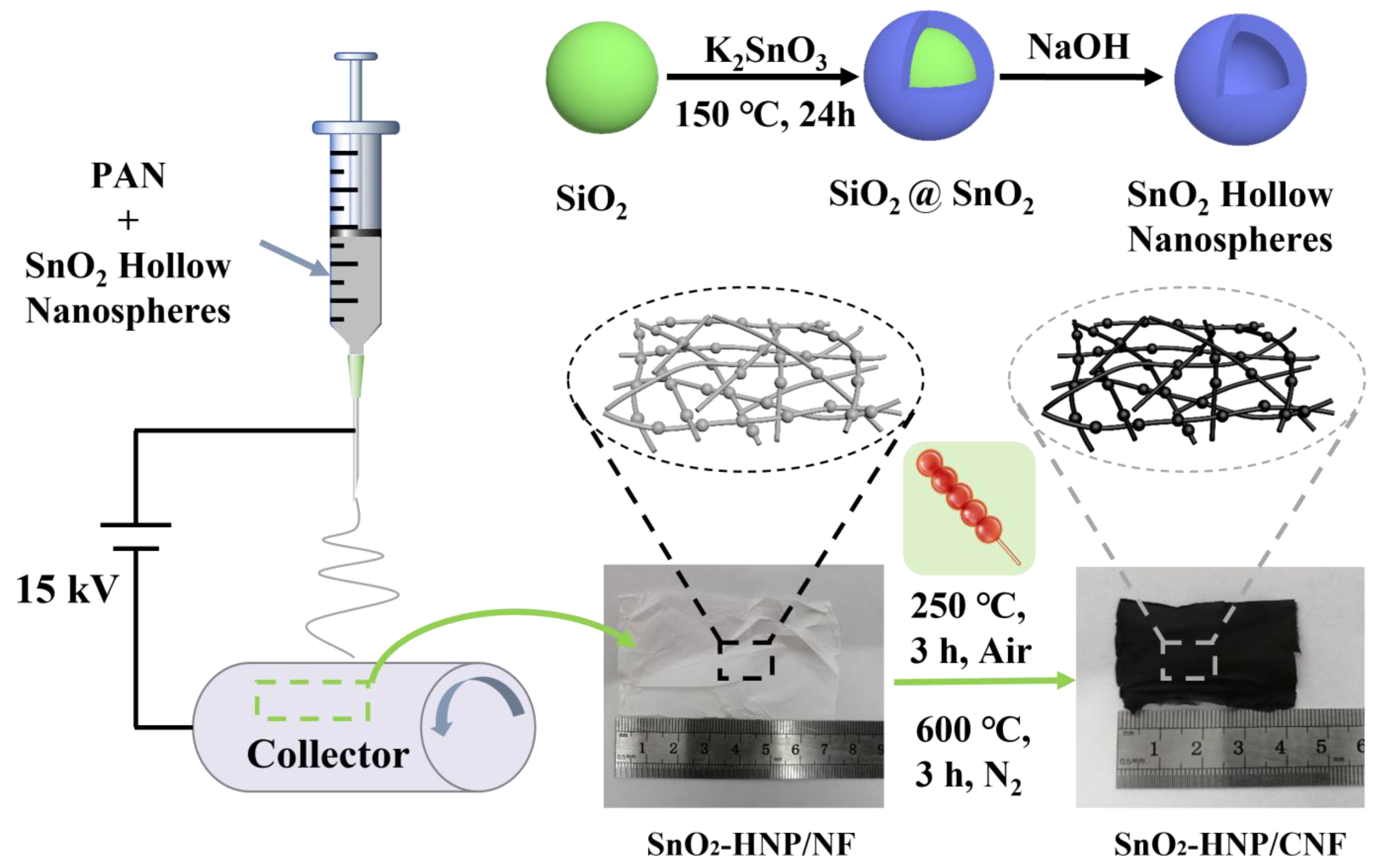
2.4. Synthesis of SnO2-HNP/CNFs

The SnO2-HNP/CNFs were designed through the electrospinning method. Briefly, SnO2-HNPs with different content (100, 200, and 300 mg) were stirred to dissolve in 5 mL of N, N-Dimethylformamide, during which process 0.4 g of polyacrylonitrile was added. After stirring for 12 h, the resulting viscous solution was loaded and the electrospun nanofibers (SnO2-HNP/NFs) were collected through aluminum foil (15 kV, 18 cm). Subsequently, the obtained SnO2-HNP/NFs were firstly stabilized in a tube furnace under air atmosphere (250 °C, 1 °C min−1, 3 h), in the train of the obtained brown nanofibers were heated at 600 °C for 3 h (2 °C min−1) under N2 atmosphere. The calcined products were denoted as SnO2-HNP/CNF-1, SnO2-HNP/CNF, and SnO2-HNP/CNF-3 according to the different content of SnO2-HNPs. Moreover, during the process of assembling Li-ion batteries, we put the flexible film (SnO2-HNP/CNF) into a mortar and ground it until crushed, naming it as SnO2-HNP/CNF-G.

2.5. Material Structure Characterization

The crystal structure of SnO2-HNP/CNFs was measured by X-ray powder diffractometer (XRD) patterns recorded on a diffractometer with Cu Ka radiation (Rigaku, Dmax2500, Tokyo, Japan). Raman spectra were recorded on a model confocal microscopy Raman spectrometer (Renishaw, RM2000, Gloucestershire, UK). X-ray photoelectron spectroscopy (XPS) was measured by X-ray instrument (Thermo Fischer, ESCALAB 250, Waltham, MA, USA). The morphology of the SnO2-HNP/CNFs was displayed by field emission scanning electron microscopy (SEM, Hitachi, S-4800, Chiyoda-ku, Japan). The specific surface area was calculated by analyzing the nitrogen adsorption–desorption isotherms of Brunauer–Emmett–Teller (BET) at 77 k (Micromeritics instrument Ltd., Tristar 3000, Norcross, GA, USA).

2.6. Electrochemical Measurement

In electrochemical experiments, we directly assembled the prepared SnO2-HNP/CNFs film as the free-standing anode electrode materials for Li-ion batteries, and the mass of the flexible electrode was about 1.5 mg. In addition, as the entire process was carried out under laboratory conditions, we chose coin cells (CR2025) for actual battery testing, including charge–discharge performance testing, rate performance testing, cycle stability testing, etc. This is because coin cells have the advantages of small size, high voltage, and relatively stable performance. The coin cells are composed of the battery shell, the prepared SnO2-HNP/CNFs anode electrode, the electrolyte (1 M LiPF6 in ethylene carbonate/dimethyl carbonate (EC/DMC, 1:1 vol%), the separator (Celgard 2400 membrane), the gasket, the spring piece, and the lithium metal as the counter electrode. Finally, we assembled all parts of the coin cells through the vacuum glovebox, and tested their battery performance using the electrochemical workstation. The specific testing parameters are as follows: the galvanostatic charge/discharge experiments were performed with a cutoff voltage window of 0.01–3.0 V using a Land Battery Measurement System (Land, Wuhan, China). The cyclic voltammetry (CV) was performed using a CS350 Electrochemical Workstation (Wuhan CorrTest Instruments Co., Ltd., Wuhan, China)

3. Results and Discussion

The overall synthesis process of SnO2-HNP/CNFs is depicted in Figure 1. In the beginning, we prepared monodisperse SiO2 nanospheres by the sol–gel method, and then employed them as the hard template to prepare SnO2-HNPs via a hydrothermal reaction. At this moment, the sugar gourd-like-shaped “gourd” part has been prepared. Subsequently, we take monodisperse SnO2-HNPs as the precursor, spin them evenly into nanofibers (SnO2-HNP/NF) via the electrospinning technology, and then prepare SnO2-HNP/CNF through subsequent heat treatment technology. In this way, SnO2-HNPs and CNFs are tightly combined, so that a complete structure of sugar gourd-like shape has been successfully prepared.
The microstructures of various products are observed by SEM. Figure 2a shows that the morphology of SiO2 nanospheres is relatively uniform, with particle sizes ranging from 180 to 230 nm, with 205 nm SiO2 nanospheres accounting for the majority. Figure 2b clearly displays that the morphology of SiO2@SnO2 nanospheres has been maintained, but the difference is that their particle size has increased (ranging from 265 to 350 nm, with 320 nm accounting for the majority). Figure 2c further illustrates that the spherical shape and the particle size of SiO2@SnO2 nanospheres after etching remain basically unchanged, indicating that the SiO2 inside has been etched off and the SnO2 hollow spherical structure has been successfully synthesized. Moreover, the products with different SnO2-HNPs contents are shown in Figure 2d,e. It can be seen that in SnO2-HNP/CNF, only a small amount of SnO2-HNPs is encapsulated in the CNFs, and the CNFs occupy the majority of the material (Figure 2d). Differently, it can be clearly seen that the SnO2-HNPs have been evenly distributed in 1D CNFs (SnO2-HNP/CNF), showing a sugar gourd-like shape (Figure 2e). The SnO2-HNP/CNF-3 product shown in Figure 2f exhibits an uneven morphology, with an excess of SnO2-HNPs loaded on each carbon nanotube. It is obvious that a large number of SnO2-HNPs are concentrated in one position, resulting in each carbon nanotube becoming finer and more prone to fracture. Moreover, energy-dispersive spectrometry (EDS) of SnO2-HNP/CNF was conducted to confirm the elemental composition, demonstrating the existence of C, N, O, and Sn elements (Figure S1). The results preliminarily confirm the formation of Sn-based oxides into the nitrogen-doped carbon nanofibers.
Figure 3a presents the XRD patterns of SnO2-HNP and SnO2-HNP/CNF. Obviously, SnO2-HNPs show a set of characteristic peaks at 26.6°, 33.8°, and 51.8°, corresponding to (110), (101), and (211) planes of the SnO2 (PDF#41-1445), respectively. However, the SnO2-HNP/CNF only displays one peak at ~24° attributed to the amorphous carbon. This situation is due to the carbon peak of the outermost CNFs masking the peak of SnO2-HNP within its structure, implying the formation of tightly packed structures. Moreover, the carbon structure property of SnO2-HNP/CNF is determined by Raman spectroscopy (Figure S2). Based on the relative intensity ratio (ID/IG = 1.05) of the D and G peaks, it is determined that SnO2-HNP/CNF contains abundant structural defects [37,38]. Such defect structure may be caused by the doping of N elements in composite material. Additionally, Brunauer–Emmett–Teller (BET) testing was also conducted to further investigate the porous structure of SnO2-HNP/CNF (Figure 3b). The calculated BET value is 85 m2 g−1, while the average pore range is approximately distributed within the range from 2 to 12 nm and concentrated at 3.80 nm. The larger BET area with abundant pores of SnO2-HNP/CNF film is conducive to the transfer of Li+ during battery charging/discharging as the integrated anode for Li-ion batteries [39]. To evaluate the mechanical strength, the stress–strain curve of SnO2-HNP/CNF flexible films is conducted (Figure S3). The SnO2-HNP/NF displays the maximal tensile break strength of 0.93 MPa and a tensile strain of 6.14%, while the SnO2-HNP/CNF exhibits the maximal tensile break strength of 0.44 MPa and a tensile strain of 3.27%. This indicates that the calcination process enabled the SnO2-HNP/CNF film to not only obtain excellent electrical conductivity but still maintain good mechanical strength, making it possible to serve as a flexible integrated anode.
To identify the chemical compositions and surface electronic structure of the SnO2-HNP/CNF, X-ray photoelectron spectroscopy (XPS) analysis was performed. Full-range XPS survey spectrum directly indicates the existence of Sn, C, N, and O in the SnO2-HNP/CNF (Figure S4), which is consistent with the EDS data. The presence of the peak without Si indicates that the SiO2 as a template has been completely etched. As shown in Figure 3c, the Sn 3d segment of XPS comes from the Sn-O bond in SnO2 lattice. The peaks occurred at 486.7 and 495.2 eV are corresponded to Sn 3d3/2 and Sn 3d5/2 spins, separately, with an energy separation of 8.5 eV confirming the valence state of the Sn atom in SnO2 (Sn4+ oxidation state) [40,41]. This also indirectly confirms the existence of SnO2 in the composites. The C 1s spectrum (Figure 3d) is divided into two peaks at 284.6 and 286.3 eV, corresponding to C-C bonds and Sn-C-O bonds, respectively. The bonding structure of nitrogen has a great influence on the properties of nitrogen-doped carbon materials, the types of nitrogen atoms doped in SnO2-HNP/CNF are examined. According to the spectra in Figure 3e, three different nitrogen species of N 1s can be observed, and the peaks at 398.5, 400.0, and 400.9 eV are consistent with pyridinic N, pyrrolic N, and graphitic N, respectively [42]. Among them, graphite N is located in the network structure of carbon, which is formed by nitrogen atoms replacing the carbon atoms in the graphite layer. It has the same configuration as graphite carbon, which can improve the conductivity of the carbon material. The pyridine N in the material can provide more active sites, which are beneficial for the storage of Li+ ion. Thereby the conductivity of the SnO2-HNP/CNF can be further improved [43,44]. As to the O 1s spectrum (Figure 3f), the three peaks centered at binding energies of 530.8, 531.9, and 532.7 eV are assigned to the Sn-O, C-O/C=O/O-C=O, and OH bonds, respectively [45]. Furthermore, to measure the content of SnO2 in SnO2-HNP/CNF, we conducted thermogravimetric testing (TG), and the results are shown in Figure S5. There are two weight-loss processes in SnO2-HNP/CNF during the heating process. The first weightlessness process occurs below 300 °C (4%), corresponding to the dehydration process of the material. The second weight-loss process occurs between 300 and 480 °C (47%), as the CNFs in the composite are oxidized into CO2. Finally, the TG curve remains at around 49%, indicating that the SnO2 content in the material is around 49%.
To evaluate the electrochemical behaviors of SnO2-HNP/CNF as anode materials for LIBs, the cyclic voltammetry (CV) curves were constructed using coin cells between 0.01 and 3 V (Figure 4a). The irreversible peak at 0.87 V appears in the first cycle and disappears during subsequent cycles. This is because the solid–electrolyte interphase (SEI) layer is formed during the first cycle. With further discharge, the reduction peak occurs at 0.35 V as a result of lithium alloying with Sn and forming LixSn. The oxidation peaks at 0.57 and 1.15 V are attributed to the dealloying of LixSn and the transition of Sn to SnO2, respectively. In addition, the following scan displays similar and overlapping CV curves, indicating the excellent reversibility of the alloying reaction between Sn and Li. Figure 4b exhibits the representative charge/discharge curves of SnO2-HNP/CNF (0.05 A g−1). In the initial discharge cycle, two voltage platforms in the charge/discharge curve correspond to the two reduction voltages in the CV curve, respectively. Moreover, the first discharge and charge capacities of SnO2-HNP/CNF reach 1136.8 and 867.1 mA h g−1, respectively. The formation of the SEI and the decomposition of the electrolyte are main causes of the capacity decay during the initial cycle. For comparison, the cycling performance of different content of SnO2 is investigated in Figure 4c. The SnO2-HNP/CNF displays the highest specific capacity (~584.3 mAh g−1 at 0.05 A g−1) and the most stable cycling performance (50 cycles), higher than those of SnO2-HNP/CNF-1 (457.2 mA h g−1) and SnO2-HNP/CNF-3 (352.1 mA h g−1). Moreover, the capacity differences between the SnO2-HNP (200.9 mA h g−1) and SnO2-HNP/CNF also demonstrate the superior performance of the composite film. Also, the SnO2-HNP/CNF-G shows a relatively low capacity (413.4 mA h g−1), which is associated with the addition of the PVDF binder. Different from an integrated electrode, grinding with the PVDF binder can induce the expansion of electrodes, causing irreversible capacity losses. Figure 4d illustrates the cycling performance of SnO2-HNP/CNF at 0.1 A g−1 current density. The reversible capacity is 692.4 mA h g−1 after 450 cycles, with a capacity retention rate of 94.2% relative to the second cycle (735.1 mA h g−1). Noteworthy, the capacity has a slight decay in the first 50 cycles and then picks up, which corresponds to the typical characteristics of metal oxide in the storage lithium processes. The reasons can be traced back to the reversible formation of a polymeric gel-like layer through electrolyte decomposition and the improvement of Li+ accessibility during further cycling [46]. The rate properties are also evaluated and shown in Figure 4e. The reversible capacities of SnO2-HNP/CNF are759.5, 590.8, 467.9, 300.1, and 164.1 mAh g−1 at 0.05, 0.1, 0.2, 0.5, and 1.0 A g−1, respectively. It is noteworthy that when the current density was reset to 0.05 A g−1, the capacity could recover to a high specific capacity of 753.1 mAh g−1, comparable to the initial discharge capacity, indicating that SnO2-HNP/CNF has good rate performance as the integrated flexible anode. The long-term cycling of SnO2-HNP/CNF exhibits that the capacity is always stable at 410.2 mAh g−1 without any degradation after continuous operation over 1000 cycles at the large current density of 1 A g−1 (Figure 4f).
The electrochemical reaction kinetics of SnO2-HNP/CNF were also investigated in detail to reveal the underlying mechanisms for outstanding performance. The CV curves at scan rates of 0.2–1 mV s−1 and the slope b values of each redox peak calculated by the equation: log i = blog ν + log a are displayed in Figure 5a,b [47,48,49]. The b value between 0.5 and 1 implies that the electrochemical capacity of SnO2-HNP/CNF is contributed by both pseudocapacitive and diffusion behaviors. Besides, the capacitive contribution at the scan rate of 1 mV s−1 is calculated and fitted by the equation: i = k1ν + k2ν1/2 [50,51]. It can be seen that the capacitive contribution at 1 mV s−1 is determined to be 62.5% (Figure 5c). Noteworthy, the capacitance contribution (from 40.2% to 62.5%) increases along with the scan rate increases (from 0.2 to 1 mV s−1) (Figure 5d). This reveals that at low current densities, the electrochemical behavior primarily exhibits diffusion control process, while it transforms into a capacitance-dominated control process in rapid charging and discharging, which contributes to excellent high-rate lithium storage performance.
To verify the practical value of SnO2-HNP/CNF, we also assembled and evaluated lithium-ion full-cell with SnO2-HNP/CNF as the anode and LiCoO2 as the cathode. The initial discharge and charge capacities of the full cell exhibit 455.8 and 455.3 mAh g−1, respectively, and there was no significant decay in the subsequent cycles (Figure 6a). It also shows a favorable cycling stability at 0.1 A g−1, with a reversible capacity of 265.7 mAh g−1 after 120 cycles, corresponding to a capacity retention rate of 65.4% and a coulombic efficiency of 100% (Figure 6b). What is more, the rate performance of the full cell based on SnO2-HNP/CNF was also examined (Figure 6c). At a high current density of 1 A g−1, the full cell based on SnO2-HNP/CNF still has a reversible capacity of 153.4 mAh g−1. Similar to the half-cells, the capacity can be restored to the initial state when the current density decreases, illustrating the excellent rate performance of SnO2-HNP/CNF. The excellent electrochemical lithium storage performance of half- and full-cells with SnO2-HNP/CNF as the flexible integrated anode can be attributed to the synergistic effect of carbon nanofibers and SnO2-HNP. Where SnO2 provides high capacities, the unique hollow structure and the encapsulation of carbon nanofibers weaken the capacity decay due to the volume expansion of SnO2, which contributes to the long-cycle stability. Not only that, the addition of flexible carbon nanofiber also avoids the use of binder and increases the electrical conductivity, ensuring the charging and discharging performance at the high current density. Owing to the above excellent performance, we conducted the LED light-up test. The flexible SnO2-HNP/CNF electrode is shown in the illustration in Figure 6d, demonstrating its good flexibility and mechanical properties. The Li+ coin full-cell assembled by SnO2-HNP/CNF flexible electrodes can also successfully light up LED lights, which verifies its practical application potential.

4. Conclusions

In summary, a novel SnO2-HNP/CNF flexible integrated electrode has been designed by combining the template method and electrospinning technology for half and full LIBs. The combination of 1D nanofibers and SnO2 hollow structure forms a sugar gourd-like shape, which not only alleviates the volume expansion and limits the growth of the SEI membrane but also enhances the overall cycling performance of electrode materials. Also, without any auxiliary additives and current collectors, the obtained membrane can be directly and conveniently implemented as the working electrode, which not only signally enhances the energy density but also partially simplifies the experimental process. Based on the above advantages, the optimized SnO2-HNP/CNF delivers excellent half/full LIBs performance. It is believed that this synthetic strategy and morphology design could be extended to the construction of other MOx-encapsulated carbon nanofibers with 3D hollow structures as the binder-free integrated anode for various energy-related applications.

Supplementary Materials

The following supporting information can be downloaded at https://www.mdpi.com/article/10.3390/nano13152226/s1. Figure S1: Energy-dispersive spectrometry (EDS) of SnO2-HNP/CNF; Figure S2: Raman spectra of SnO2-HNP/CNF; Figure S3: Stress–strain curve of SnO2-HNP/CNF and SnO2-HNP/NF; Figure S4: XPS survey of SnO2-HNP/CNF; Figure S5: Thermogravimetric analysis (TGA) of SnO2-HNP/CNF under air with a ramp rate of 5 °C min−1.

Author Contributions

Conceptualization, Y.L.; methodology, Q.S.; formal analysis, J.L.; investigation, X.Y.; data curation, R.G.; writing—original draft preparation, J.L. and Y.L.; writing—review and editing, Q.S.; supervision, J.Y. All authors have read and agreed to the published version of the manuscript.

Funding

This research was supported by the Science and Technology Department of Jilin Province (grant YDZJ202201ZYTS369), the Education Department of Jilin Province (JJKH20220186KJ), and Jilin Engineering Normal University (BSKJ202110).

Data Availability Statement

The data is available on reasonable request from the corresponding author.

Conflicts of Interest

The authors declare no conflict of interest.

References

  1. Tarascon, J.-M.; Armand, M. Issues and Challenges Facing Rechargeable Lithium Batteries. Nature 2001, 414, 359–367. [Google Scholar] [CrossRef] [PubMed]
  2. Goodenough, J.B.; Park, K.-S. The Li-Ion Rechargeable Battery: A Perspective. J. Am. Chem. Soc. 2013, 135, 1167–1176. [Google Scholar] [CrossRef]
  3. Lu, L.; Hu, Y.; Dai, K. The Advance of Fiber-Shaped Lithium Ion Batteries. Mater. Today Chem. 2017, 5, 24–33. [Google Scholar] [CrossRef]
  4. Xu, J.; Cai, X.; Cai, S.; Shao, Y.; Hu, C.; Lu, S.; Ding, S. High-Energy Lithium-Ion Batteries: Recent Progress and a Promising Future in Applications. Energy Environ. Mater. 2022, e12450. [Google Scholar] [CrossRef]
  5. Mukherjee, S.; Albertengo, A.; Djenizian, T. Beyond Flexible-Li-Ion Battery Systems for Soft Electronics. Energy Storage Mater. 2021, 42, 773–785. [Google Scholar] [CrossRef]
  6. Chen, K.; Yang, H.; Liang, F.; Xue, D. Microwave-Irradiation-Assisted Combustion toward Modified Graphite as Lithium Ion Battery Anode. ACS Appl. Mater. Interfaces 2018, 10, 909–914. [Google Scholar] [CrossRef]
  7. Du, J.; Li, Q.; Chai, J.; Jiang, L.; Zhang, Q.; Han, N.; Zhang, W.; Tang, B. Review of Metal Oxides as Anode Materials for Lithium-Ion Batteries. Dalton Trans. 2022, 51, 9584–9590. [Google Scholar] [CrossRef]
  8. Yuan, T.; Tang, R.; Xiao, F.; Zuo, S.; Wang, Y.; Liu, J. Modifying SiO as a Ternary Composite Anode Material((SiOx/G/SnO2)@C) for Lithium Battery with High Li-Ion Diffusion and Lower Volume Expansion. Electrochim. Acta 2023, 439, 141655. [Google Scholar] [CrossRef]
  9. Tran, Q.N.; Choi, H.W. Development of Cellulose Nanofiber-SnO2 Supported Nanocomposite as Substrate Materials for High-Performance Lithium-Ion Batteries. Nanomaterials 2023, 13, 1080. [Google Scholar] [CrossRef]
  10. Qin, J.; He, C.; Zhao, N.; Wang, Z.; Shi, C.; Liu, E.-Z.; Li, J. Graphene Networks Anchored with Sn@Graphene as Lithium Ion Battery Anode. ACS Nano 2014, 8, 1728–1738. [Google Scholar] [CrossRef]
  11. Li, B.; Cao, H.; Zhang, J.; Qu, M.; Lian, F.; Kong, X. SnO2-Carbon-RGO Heterogeneous Electrode Materials with Enhanced Anode Performances in Lithium Ion Batteries. J. Mater. Chem. 2012, 22, 2851–2854. [Google Scholar] [CrossRef]
  12. Yue, L.; Xue, C.; Huang, B.; Xu, N.; Guan, R.; Zhang, Q.; Zhang, W. High Performance Hollow Carbon@SnO2@graphene Composite Based on Internal-External Double Protection Strategy for Lithium Ion Battery. Electrochim. Acta 2016, 220, 222–230. [Google Scholar] [CrossRef]
  13. Gervillié, C.; Boisard, A.; Labbé, J.; Guérin, K.; Berthon-Fabry, S. Relationship between Tin Environment of SnO2 Nanoparticles and Their Electrochemical Behaviour in a Lithium Ion Battery. Mater. Chem. Phys. 2021, 257, 123461. [Google Scholar] [CrossRef]
  14. Yu, H.; Zhang, Y.; Li, L.; Ding, Z.; Chen, Y.; Yuan, Q.; Sun, R.; Li, K.; Liu, C.; Wu, J. SnO2 Nanoparticles Embedded in 3D Hierarchical Honeycomb-like Carbonaceous Network for High-Performance Lithium Ion Battery. J. Alloys Compd. 2021, 858, 157716. [Google Scholar] [CrossRef]
  15. Zhang, L.; Deng, N.; Kang, J.; Wang, X.; Gao, H.; Liu, Y.; Wang, H.; Wang, G.; Cheng, B.; Kang, W. Enhanced Ionic Conductivity in a Novel Composite Electrolyte Based on Gd-Doped SnO2 Nanotubes for Ultra-Long-Life All-Solid-State Lithium Metal Batteries. J. Energy Chem. 2023, 77, 326–337. [Google Scholar] [CrossRef]
  16. Suzuki, T.; Cheng, J.; Qiao, L.; Xing, Y.; Zhang, M.F.; Nishijima, H.; Yano, T.; Pan, W. Preparation of SnO2 Nanotubes via a Template-Free Electrospinning Process. RSC Adv. 2020, 10, 22113–22119. [Google Scholar] [CrossRef]
  17. Yan, J.; Zhou, C.; Wang, L.; Zhuang, Y.; Zhong, M.; Zhang, J.; Lei, P.; Li, Y.; Shen, W.; Guo, S. Effects of Pulverization and Dead Sn Accumulation in SnO2 Nanorods Grown on Carbon Cloth on Their Electrochemical Performances as the Anode in Lithium Ion Batteries. ACS Appl. Energy Mater. 2022, 5, 3536–3544. [Google Scholar] [CrossRef]
  18. Wang, Y.; Jin, Y.; Zhao, C.; Pan, E.; Jia, M. 1D Ultrafine SnO2 Nanorods Anchored on 3D Graphene Aerogels with Hierarchical Porous Structures for High-Performance Lithium/Sodium Storage. J. Colloid Interface Sci. 2018, 532, 352–362. [Google Scholar] [CrossRef]
  19. Long, J.; Han, T.; Ding, Y.; Hu, C.; Liu, J. Co-Coating ZnCo2O4 and Carbon on a Biomimetic Sea Anemone-Shaped SnO2 Mesostructure for High-Performance Lithium-Ion Batteries and Semi-Solid Lithium Slurry Batteries. Appl. Surf. Sci. 2022, 591, 153220. [Google Scholar] [CrossRef]
  20. Huang, B.; Li, X.; Pei, Y.; Li, S.; Cao, X.; Massé, R.C.; Cao, G. Novel Carbon-Encapsulated Porous SnO2 Anode for Lithium-Ion Batteries with Much Improved Cyclic Stability. Small 2016, 12, 1945–1955. [Google Scholar] [CrossRef]
  21. Huang, J.; Dai, Q.; Wu, Q.; Ren, H.; Lu, X.; Gu, C.; Zhang, Y.; Woo Joo, S. Preparation of Hollow SnO2@N-C Nanospheres for High Performance Lithium-Ion Battery. J. Electroanal. Chem. 2022, 922, 116741. [Google Scholar] [CrossRef]
  22. Choi, J.; Myung, Y.; Gu, M.G.; Kim, S.-K. Nanohybrid Electrodes of Porous Hollow SnO2 and Graphene Aerogel for Lithium Ion Battery Anodes. J. Ind. Eng. Chem. 2019, 71, 345–350. [Google Scholar] [CrossRef]
  23. Li, B.; Bi, R.; Yang, M.; Gao, W.; Wang, J. Coating Conductive Polypyrrole Layers on Multiple Shells of Hierarchical SnO2 Spheres and Their Enhanced Cycling Stability as Lithium-Ion Battery Anode. Appl. Surf. Sci. 2022, 586, 152836. [Google Scholar] [CrossRef]
  24. Tang, M.; Ma, X.; Niu, Y.-B.; Zhao, W. Engineering Design of Graphene Tightly Wrapped Hollow Structure for Boosted Lithium Storage in Conversion/Alloying Electrode: A Case of SnO2. Scr. Mater. 2022, 214, 114649. [Google Scholar] [CrossRef]
  25. Zhu, S.; Liu, J.; Sun, J. Growth of Ultrathin SnO2 on Carbon Nanotubes by Atomic Layer Deposition and Their Application in Lithium Ion Battery Anodes. Appl. Surf. Sci. 2019, 484, 600–609. [Google Scholar] [CrossRef]
  26. Liu, K.; Zhu, S.; Dong, X.; Huang, H.; Qi, M. Ionic Liquid-Assisted Anchoring SnO2 Nanoparticles on Carbon Nanotubes as Highly Cyclable Anode of Lithium Ion Batteries. Adv. Mater. Interfaces 2020, 7, 1901916. [Google Scholar] [CrossRef]
  27. Mao, H.; Shi, L.; Song, S.; Xiao, C.; Liang, J.; Dong, B.; Ding, S. N-Doped Hollow Carbon Nanosheet Supported SnO2 Nanoparticles. Inorg. Chem. Front. 2017, 4, 1742–1747. [Google Scholar] [CrossRef]
  28. Jiang, W.; Xiong, D.; Wu, S.; Gao, J.; Wu, K.; Li, W.; Feng, Y.; He, M.; Feng, Z. Carbon Nanosheets Wrapped in SnO2-TiO2 Nanoparticles as a High Performance Anode Material for Lithium Ion Batteries. Ceram. Int. 2022, 48, 27174–27181. [Google Scholar] [CrossRef]
  29. Gao, X.; Tang, Z.; Meng, M.; Yu, Q.; Zhu, Y.; Shen, S.; Yang, J. Synthesis of Crumpled SnO2/RGO Nanocomposites with 2D-in-3D Structure and High Performance. Mater. Chem. Phys. 2020, 253, 123298. [Google Scholar] [CrossRef]
  30. Zhang, D.; Bi, C.; Wu, Q.; Hou, G.; Zheng, G.; Wen, M.; Tang, Y. Co3Sn2/SnO2 Nanocomposite Loaded on Cu Foam as High-Performance Three-Dimensional Anode for Lithium-Ion Batteries. New J. Chem. 2019, 43, 1238–1246. [Google Scholar] [CrossRef]
  31. Liu, W.; Lu, B.; Liu, X.; Gan, Y.; Zhang, S.; Shi, S. In Situ Synthesis of the Peapod-Like Cu-SnO2@Copper Foam as Anode with Excellent Cycle Stability and High Area Specific Capacity. Adv. Funct. Mater. 2021, 31, 2101999. [Google Scholar] [CrossRef]
  32. Keshavarz, S.; Okoro, O.V.; Hamidi, M.; Derakhshankhah, H.; Azizi, M.; Mohammad Nabavi, S.; Gholizadeh, S.; Amini, S.M.; Shavandi, A.; Luque, R.; et al. Synthesis, Surface Modifications, and Biomedical Applications of Carbon Nanofibers: Electrospun vs Vapor-Grown Carbon Nanofibers. Coord. Chem. Rev. 2022, 472, 214770. [Google Scholar] [CrossRef]
  33. Lu, L.; Cao, X.; Shen, Z.; Li, L.; Huo, J.; Chen, W.; Liu, C.; Liu, H. Electrospun Nitrogen-Doped Carbon Nanofibers for Electrocatalysis. Sustain. Mater. Technol. 2020, 26, e00221. [Google Scholar] [CrossRef]
  34. Lee, K.H.; Lee, S.H.; Ruoff, R.S. Synthesis of Diamond-Like Carbon Nanofiber Films. ACS Nano 2020, 14, 13663–13672. [Google Scholar] [CrossRef]
  35. Guo, J.; Liu, J.; Dai, H.; Zhou, R.; Wang, T.; Zhang, C.; Ding, S.; Wang, H. Nitrogen Doped Carbon Nanofiber Derived from Polypyrrole Functionalized Polyacrylonitrile for Applications in Lithium-Ion Batteries and Oxygen Reduction Reaction. J. Colloid Interface Sci. 2017, 507, 154–161. [Google Scholar] [CrossRef]
  36. Xu, Y.; Zhu, Y.; Liu, Y.; Wang, C. Electrochemical Performance of Porous Carbon/Tin Composite Anodes for Sodium-Ion and Lithium-Ion Batteries. Adv. Energy Mater. 2013, 3, 128–133. [Google Scholar] [CrossRef]
  37. Ferrari, A.C.; Robertson, J. Interpretation of Raman Spectra of Disordered and Amorphous Carbon. Phys. Rev. B 2000, 61, 14095–14107. [Google Scholar] [CrossRef] [Green Version]
  38. Shao, Q.; Liu, J.; Wu, Q.; Li, Q.; Wang, H.; Li, Y.; Duan, Q. In Situ Coupling Strategy for Anchoring Monodisperse Co9S8 Nanoparticles on S and N Dual-Doped Graphene as a Bifunctional Electrocatalyst for Rechargeable Zn-Air Battery. Nano-Micro Lett. 2019, 11, 4. [Google Scholar] [CrossRef] [Green Version]
  39. Li, Y.; Song, Z.; Sun, T.; Shen, Y.; Lv, X.; Xu, D.; Wang, H. Well-Dispersed Sb2O3 Nanoparticles Encapsulated in Multi-Channel-Carbon Nanofibers as High-Performance Anode Materials for Li/Dual-Ion Batteries. Int. J. Hydrogen Energy 2021, 46, 26308–26317. [Google Scholar] [CrossRef]
  40. Cheng, Y.; Huang, J.; Qi, H.; Cao, L.; Yang, J.; Xi, Q.; Luo, X.; Yanagisawa, K.; Li, J. Adjusting the Chemical Bonding of SnO2@CNT Composite for Enhanced Conversion Reaction Kinetics. Small 2017, 13, 1700656. [Google Scholar] [CrossRef]
  41. Zhang, Y.; Hu, Z.; Liang, Y.; Yang, Y.; An, N.; Li, Z.; Wu, H. Growth of 3D SnO2 Nanosheets on Carbon Cloth as a Binder-Free Electrode for Supercapacitors. J. Mater. Chem. A 2015, 3, 15057–15067. [Google Scholar] [CrossRef]
  42. Malitesta, C.; Losito, I.; Sabbatini, L.; Zambonin, P.G. New Findings on Polypyrrole Chemical Structure by XPS Coupled to Chemical Derivatization Labelling. J. Electron Spectrosc. Relat. Phenom. 1995, 76, 629–634. [Google Scholar] [CrossRef]
  43. Ma, C.; Shao, X.; Cao, D. Nitrogen-Doped Graphene Nanosheets as Anode Materials for Lithium Ion Batteries: A First-Principles Study. J. Mater. Chem. 2012, 22, 8911–8915. [Google Scholar] [CrossRef]
  44. Yu, X.-Y.; Hu, H.; Wang, Y.; Chen, H.; Lou, X.W. (David) Ultrathin MoS2 Nanosheets Supported on N-Doped Carbon Nanoboxes with Enhanced Lithium Storage and Electrocatalytic Properties. Angew. Chem. Int. Ed. 2015, 127, 7503–7506. [Google Scholar] [CrossRef]
  45. Li, Y.; Zhu, S.; Liu, Q.; Gu, J.; Guo, Z.; Chen, Z.; Feng, C.; Zhang, D.; Moon, W.-J. Carbon-Coated SnO2@C with Hierarchically Porous Structures and Graphite Layers inside for a High-Performance Lithium-Ion Battery. J. Mater. Chem. 2012, 22, 2766–2773. [Google Scholar] [CrossRef]
  46. Xia, L.; Wang, S.; Liu, G.; Ding, L.; Li, D.; Wang, H.; Qiao, S. Flexible SnO2/N-Doped Carbon Nanofiber Films as Integrated Electrodes for Lithium-Ion Batteries with Superior Rate Capacity and Long Cycle Life. Small 2016, 12, 853–859. [Google Scholar] [CrossRef] [PubMed]
  47. Gao, S.; He, Y.; Yue, G.; Li, H.; Li, S.; Liu, J.; Miao, B.; Bai, J.; Cui, Z.; Wang, N.; et al. Pea-like MoS2@NiS1.03-Carbon Heterostructured Hollow Nanofibers for High-Performance Sodium Storage. Carbon Energy 2023, 5, e319. [Google Scholar] [CrossRef]
  48. Jiang, Y.; Xie, M.; Wu, F.; Ye, Z.; Zhang, Y.; Wang, Z.; Zhou, Y.; Li, L.; Chen, R. Cobalt Selenide Hollow Polyhedron Encapsulated in Graphene for High-Performance Lithium/Sodium Storage. Small 2021, 17, 2102893. [Google Scholar] [CrossRef]
  49. Cheng, Y.; Wang, S.; Zhou, L.; Chang, L.; Liu, W.; Yin, D.; Yi, Z.; Wang, L. SnO2 Quantum Dots: Rational Design to Achieve Highly Reversible Conversion Reaction and Stable Capacities for Lithium and Sodium Storage. Small 2020, 16, 2000681. [Google Scholar] [CrossRef]
  50. Xie, F.; Zhao, S.; Bo, X.; Li, G.; Fei, J.; Ahmed, E.-A.M.A.; Zhang, Q.; Jin, H.; Wang, S.; Lin, Z. A Robust Solvothermal-Driven Solid-to-Solid Transition Route from Micron SnC2O4 to Tartaric Acid-Capped Nano-SnO2 Anchored on Graphene for Superior Lithium and Sodium Storage. J. Mater. Chem. 2023, 11, 53–67. [Google Scholar] [CrossRef]
  51. Xu, Q.; Li, Y.; Wu, C.; Sun, X.; Li, Q.; Zhang, H.; Yu, L.; Pan, Y.; Wang, Y.; Guo, S.; et al. Kinetically Accelerated and High-Mass Loaded Lithium Storage Enabled by Atomic Iron Embedded Carbon Nanofibers. Nano Res. 2022, 15, 6176–6183. [Google Scholar] [CrossRef]
Figure 1. Synthesis diagram of SnO2-HNP/CNFs.
Nanomaterials 13 02226 g001
Figure 2. SEM images of (a) SiO2, (b) SiO2@SnO2, (c) SnO2-HNPs, (d) SnO2-HNP/CNF-1, (e) SnO2-HNP/CNF, and (f) SnO2-HNP/CNF-3.
Nanomaterials 13 02226 g002
Figure 3. (a) XRD patterns of SnO2-HNP and SnO2-HNP/CNF. (b) N2 adsorption−desorption isotherms and the pore size distribution (inset) of SnO2-HNP/CNF. High-resolution XPS spectra of Sn 3d (c), C 1s (d), N 1s (e), and O 1s (f) for SnO2-HNP/CNF.
Nanomaterials 13 02226 g003
Figure 4. Electrochemical performance of SnO2-HNP/CNF in half LIBs. (a) CV curves at 0.1 mV s−1. (b) Charge/discharge curves at 0.05 A g−1. (c) Cycling performance of various products at 0.05 A g−1. (d) Cycling performance of SnO2-HNP/CNF at 0.1 A g−1. (e) Rate performance at different current densities. (f) Cycling performance of SnO2-HNP/CNF at 1 A g−1.
Nanomaterials 13 02226 g004
Figure 5. Kinetic analysis of SnO2-HNP/CNF in half LIBs. (a) CV curves at different scan rates. (b) b−value using the relationship between peak current and scan rate. (c) Capacitive contribution at 1 mV s−1. (d) Contribution ratio of capacitive at various scan rates.
Nanomaterials 13 02226 g005
Figure 6. Electrochemical performance of SnO2-HNP/CNF in full LIBs. (a) Charge/discharge curves and (b) cycling performance at 0.1 A g−1. (c) Rate performance at different current densities. (d) Coin full battery lighting electronic thermometer.
Nanomaterials 13 02226 g006
Disclaimer/Publisher’s Note: The statements, opinions and data contained in all publications are solely those of the individual author(s) and contributor(s) and not of MDPI and/or the editor(s). MDPI and/or the editor(s) disclaim responsibility for any injury to people or property resulting from any ideas, methods, instructions or products referred to in the content.

