Article

Nontraditional Movement Behavior of Skyrmion in a Circular-Ring Nanotrack

College of Sciences, Northeastern University, Shenyang 110819, China
*
Authors to whom correspondence should be addressed.
Nanomaterials 2023, 13(22), 2977; https://doi.org/10.3390/nano13222977
Submission received: 31 October 2023 / Revised: 16 November 2023 / Accepted: 18 November 2023 / Published: 20 November 2023
(This article belongs to the Special Issue Advances in Nanoscale Magnetism and Spintronics)

Abstract

:
Magnetic skyrmions are considered promising candidates for use as information carriers in future spintronic devices. To achieve the development of skyrmion-based spintronic devices, a reasonable and feasible nanotrack is essential. In this paper, we conducted a study on the current-driven skyrmion movement in a circular-ring-shaped nanotrack. Our results suggest that the asymmetry of the inside and outside boundary of the circular ring changed the stable position of the skyrmion, causing it to move like the skyrmion Hall effect when driven by currents. Moreover, the asymmetric boundaries have advantages in enhancing or weakening the skyrmion Hall effect. Additionally, we also compared the skyrmion Hall effect from the asymmetric boundary of circular-ring nanotracks with that from the inhomogeneous Dzyaloshinskii–Moriya interaction. It was found that the skyrmion Hall effect in the circular ring is significantly greater than that caused by the inhomogeneous Dzyaloshinskii–Moriya interaction. These results contribute to our understanding of the skyrmion dynamics in confined geometries and offer an alternative method for controlling the skyrmion Hall effect of skyrmion-based devices.

1. Introduction

Skyrmions are fascinating particle-like swirling spin configurations that have garnered significant attention since their inception [1,2]. Their topological properties make them incredibly stable and endow them with exotic particle dynamics behavior [3,4,5]. Moreover, the successful experimental observation and controllability of skyrmions in a wide temperature range and near-zero field opened the door for their application in spintronic devices [2,6,7,8,9,10]. Due to the topological stability, low driving current, and small size, skyrmions are expected to further enhance the performance of spin electronic devices [11,12,13,14]. In other words, the development of skyrmion-based devices is expected to improve the current information storage capacity of devices.
It is well known that when driven by the current, the skyrmion Hall effect (SkHE) causes skyrmions to drift away from the driving current direction [15,16,17]. The processing of SkHE is one crucial factor in advancing skyrmion-based devices. In the past, the SkHE was viewed as a harmful problem for devices, and great efforts were made to suppress it [18,19]. However, recent research has shown that the SkHE can be utilized to design various devices [16,20,21,22,23,24,25,26,27,28,29]. For example, Hong et al. take advantage of skyrmions’ large transverse motion induced by SkHE-designed transistors [20]. Whang et al. proposed a fast and robust oscillator that utilizes the SkHE to modulate the skyrmion’s movement [27]. Additionally, several diodes have been proposed and implemented using the SkHE-induced unidirectional transportation of skyrmions [24,25,26,29]. In other words, the SkHE can control the movement of the skyrmion when it performs different functions in devices.
Apart from controlling the SkHE, the effect of nanotrack boundaries on the skyrmion movement in skyrmion-based devices cannot be disregarded. Studies have indicated that the nanotrack’s boundaries have a significant impact on the behavior of skyrmions [24,30,31,32,33,34,35,36,37,38,39,40]. As reported by Leonov et al., the edge state not only repulses skyrmions, but also attracts them and guides their movement [36,37]. Additionally, Saidi et al. observed that skyrmions shrink in size and follow a spiral path as they approach the edge of the track [38]. Another study conducted by Morshed’s team revealed that the boundary with notches has a significant pinning effect on skyrmions [39]. Inspired by this motivation, we investigate the current-driven behavior of skyrmions in circular-ring nanotracks. Compared with the symmetrical straight nanotrack, the inner and outer boundaries of the circular ring are asymmetric, which may induce some special phenomena.

2. Materials and Methods

We modeled ultra-thin ferromagnetic Co/Pt with a circular-ring nanotrack, as shown in Figure 1a, which can be experimentally fabricated using lithography techniques [41,42]. Our simulations were carried out using the mumax3 software package (version 3.6) [43,44]. The circular-ring nanotrack was parametrized as γ O = R m ( e x c o s θ + e y sin θ ) , where Rm is the middle line radius of the track and (ex, ey) is the Cartesian basis. The simulation mesh was divided into 110 × 110 × 1 grids with a cell size of 2 × 2 × h nm3, where h represents the thickness of the track. The choice of cell size was much lower than the exchange length lex and skyrmion size (approximately 13.5 nm in our simulation). To maintain accuracy, we chose a 2 nm cell size, which was also used for Co/Pt in other literature [32,38,39]. Under zero field, skyrmions with two polarities are stabilized at the initial center of the track because of the uniaxial anisotropy. There is a certain range of Ku values that can ensure the stable injection of an isolated skyrmion [45]. In our system, only when 6.1 × 10 5   J m 3 K u 9.2 × 10 5   J m 3 can we obtain a stable circular skyrmion, while when 4.4 × 10 5   J m 3 < K u < 6.2 × 10 5   J m 3 is an elliptical instability state and when K u 4.4 × 10 5   J m 3 , irregular magnetic domains or helical vortex states appear. In experiments, skyrmion can be produced through electric pulse, magnetic field, and other methods [46,47]. Then, we injected an in-plane current to drive the skyrmion moving along the circular-ring nanotrack. The red arrows in Figure 1a represent the clockwise (CW) and counterclockwise (CCW) directions of the current, which were both equally dispersed across the circular ring. We refer to the situation of the skyrmion traveling clockwise in the full text as CW, and the case of the skyrmion traveling counterclockwise as CCW.
The magnetization dynamics driven by an in-plane current are governed by the Landau–Lifshitz–Gilbert equation containing the spin-transfer torque (STT) effect:
m ˙ = γ m × H e f f + α m × m ˙ + m × m × ( u ) m + β m × ( u ) m .
where γ is the gyromagnetic ratio, m = M/Ms is the normalized magnetization vector, and Ms is the saturation magnetization. The effective magnetic field is given by H e f f = ( δ E / δ m ) / μ 0 M s , where μ 0 is the vacuum permeability, and E is the magnetic energy of the system, including energy terms such as exchange, anisotropy, Dzyaloshinskii–Moriya interaction (DMI), Zeeman, and demagnetization energy. The interfacial DMI energy density is given by E DM = D M m ( ( z ^ × ) × m ) , where DM is the DMI constant. For μ = μ B j p / e M s , j is the current density, p is the spin polarization rate, μ B is the Bohr magneton, and e is the electron charge. α and β are the Gilbert damping constant and the non-adiabaticity factor, respectively. We chose the case α = β = 0.01 here to exclude the intrinsic SkHE [15,48]. The magnetic parameters we used here are as follows: M s = 5.8 × 10 5   A m 1 , A = 15 × 10 12   J m 1 , D M = 3 × 10 3   J m 2 , K u = 8 × 10 5   J m 3 , p = 0.5.

3. Results

The functions between skyrmion velocity and the position in the circular-ring nanotrack enabled us to determine the dynamics of the skyrmion. We calculated the skyrmion velocity and decomposed it into two components, parallel velocity VT and perpendicular velocity VN, where VT (VN) is the velocity component along (perpendicular to) the current direction. The positive directions of VT and VN are along e T and e N , where e T is the tangent direction of the circular ring, and e N is the normal direction of the circular ring. It can be seen from Figure 1b that VT shows a periodic trend of increasing first and then decreasing in both CCW and CW directions, where the VT of CCW (CW) with Q = −1 overlaps with CW(CCW) with Q = 1. This fluctuation also occurs in VN, as shown in Figure 1c, which fluctuates over a non-zero value and has the same periodicity as VT. This fluctuation of velocity is significantly different from the case in a straight track. In a straight track, the velocity remains constant in parallel and zero in the perpendicular direction for α = β . However, in the circular-ring nanotrack, the velocity fluctuates significantly. To compare the movement behavior of a skyrmion in the straight and circular-ring tracks, we define Rsk as the radius of the real moving trajectory and compare it with the middle line radius of the circular ring Rm. Here, we let Rd = RmRsk, and Rd is the distance between the middle line and the skyrmion’s real moving trajectory. Figure 1d shows the variation in Rd with the angle position. The initial non-zero value of Rd indicates that the skyrmion undergoes a transverse drift from the middle line. This means that the skyrmion first stabilizes inside the middle line and then moves towards the inner or outer boundary driven by the current.
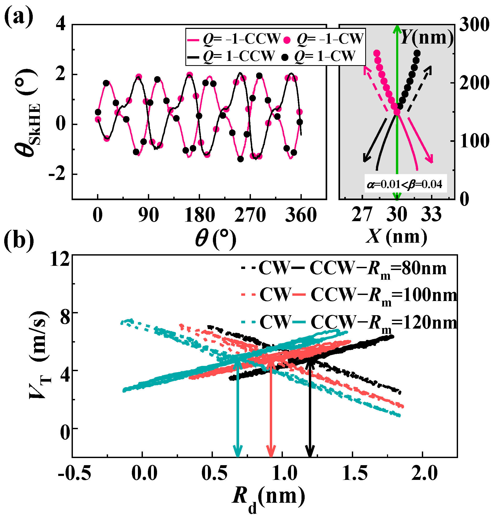
Upon the observation of skyrmion movement in the circular-ring nanotrack, we found that the skyrmion moves at a certain angle to the driving current, similar to the movement caused by the skyrmion Hall effect (SkHE). We calculated the Hall angle θ SkHE in the circular-ring nanotrack and show it in Figure 2a, where θ SkHE = arctan ( V N / V T ) . It is obvious that the Hall angle is non-zero, and the maximum value is about 2°. We found that this type of SkHE still exists for different track thicknesses (h = 0.4 nm and h = 1 nm). In traditional SkHE, the key influencing factors are the skyrmion movement direction and the topological number Q, as shown in the gray section of Figure 2a. Similar to the traditional SkHE, the Hall angle in the circular-ring nanotrack also demonstrates a notable reliance on both the skyrmion movement direction and the topological number Q. For a skyrmion with Q = −1, the CCW current drives it towards the inner side, while the CW current drives it towards the outer side of the circular-ring nanotrack. The situation is exactly the opposite for a skyrmion with Q = 1.
Based on the obtained results, it can be concluded that the movement of skyrmions in circular-ring nanotracks is similar to the SkHE. However, the SkHE does not occur in the straight nanotrack when α = β . This leads us to assume that the SkHE observed in circular rings may be due to the asymmetric inner and outer boundaries of the circular ring. In Figure 2b, we show the function of VT and the drift distance Rd for different Rm. It can be found that VT is linearly related to Rd in both movement directions: it is just a negative correlation in CW and a positive correlation in CCW. The situations when Q = 1 are the opposite. Furthermore, special attention should be paid to the fact that the stable positions of the skyrmion, represented by the intersection of the velocities in two directions, vary significantly for circular-ring nanotracks of different sizes. The size of the circular-ring nanotrack has a direct impact on the stable position of the skyrmion. As the size of the ring decreases, its curvature becomes more prominent, resulting in less symmetry between its inner and outer boundaries. Conversely, larger circular rings appear more symmetrical, with smaller differences between the inner and outer boundaries. Due to the asymmetric boundary of the circular-ring nanotrack, the stable position of the skyrmion drifts farther from the middle line as the circular-ring nanotrack size decreases. As a result, the Rd (initial position) in Figure 1d is not zero. When a skyrmion moves along a straight track, it remains stable on the middle line without deviation. However, when a skyrmion moves along a circular-ring track, the collision between the skyrmion and the asymmetric boundaries results in a periodic change in the skyrmion’s Hall angle. This, in turn, leads to periodic increases and decreases in skyrmion velocity. Therefore, the period of such collisions is uncertain. When we modify the size of the nanotrack or the driving current density, the SkHE still exhibits an oscillation mode, but the period changes accordingly. In topological memory with half-vortices pairs and half-antivortices pairs as information storage carriers, the ring-shaped boundary also plays an important role in its functioning. According to the research by Metlov, the use of multiple connected elements constructed by the ring-shaped boundary can greatly increase the information storage capacity of the topological memory [49].
To obtain a deeper understanding of how asymmetric boundaries affect the movement of skyrmions in circular-ring nanotracks, the Thiele equation is utilized. Since the size of skyrmion changes is not obvious and the topological structure is maintained, we still treat the skyrmion as a rigid object in the asymmetric track. This rigid approximation allows the Thiele equation for the skyrmion to be written as:
G × ( V e V sk ) + D ( β V e α V sk ) U = 0 ,
where the first term is the Magnus force, G is the gyrovector related to the topological number Q of skyrmion, and G = (0, 0, 4πQ) is a constant for the Néel skyrmion. The second term of Equation (2) stands for the dissipative force and the D comes from a dimensionless matrix related to the dissipative force, being its components Dxx = Dyy = D. V e = ( V e , 0 ) = ( P l 3 j / 2 e M s , 0 ) is the velocity of the electron, and l is the lattice constant of the material. Vsk = (VT, VN) is the skyrmion velocity that can be decomposed into two orthogonal parts (the tangential e T and normal e N directions of the circular-ring nanotrack). The third term, U , represents the force F acting on the moving skyrmion and F = (FT, FN), including the forces from the boundary and driving current.
For α = β , we can obtain the simplification form of the skyrmion velocity from Equation (2):
V sk = V T V N = 1 G 2 + α 2 D 2 ( G 2 + α 2 D 2 ) V e + α D F T + G F N G F T + α D F N
Considering D = |G| and α 1   ( α 2 + 1 1 ) , the function of velocity can be further simplified as:
V T = V e + α F T D F N G V N = α F N D + F T G  
It can be concluded from Equation (4) that the VT is determined by the sign of V e and the product of G (Q) and FN. The force FN acting on the skyrmion mainly comes from the repulsive force from the boundary. When a skyrmion moves towards the inner boundary, the force FN is negative. On the other hand, when a skyrmion moves towards the outer boundary, the force FN is positive. For a skyrmion with Q = −1, when it moves counterclockwise and approaches the inner boundary, its velocity increases. However, when it approaches the outer boundary, its velocity decelerates. For skyrmions with Q = 1, the situation is the opposite, since G is positive. This is consistent with the variations in skyrmion velocity described in Figure 1b.
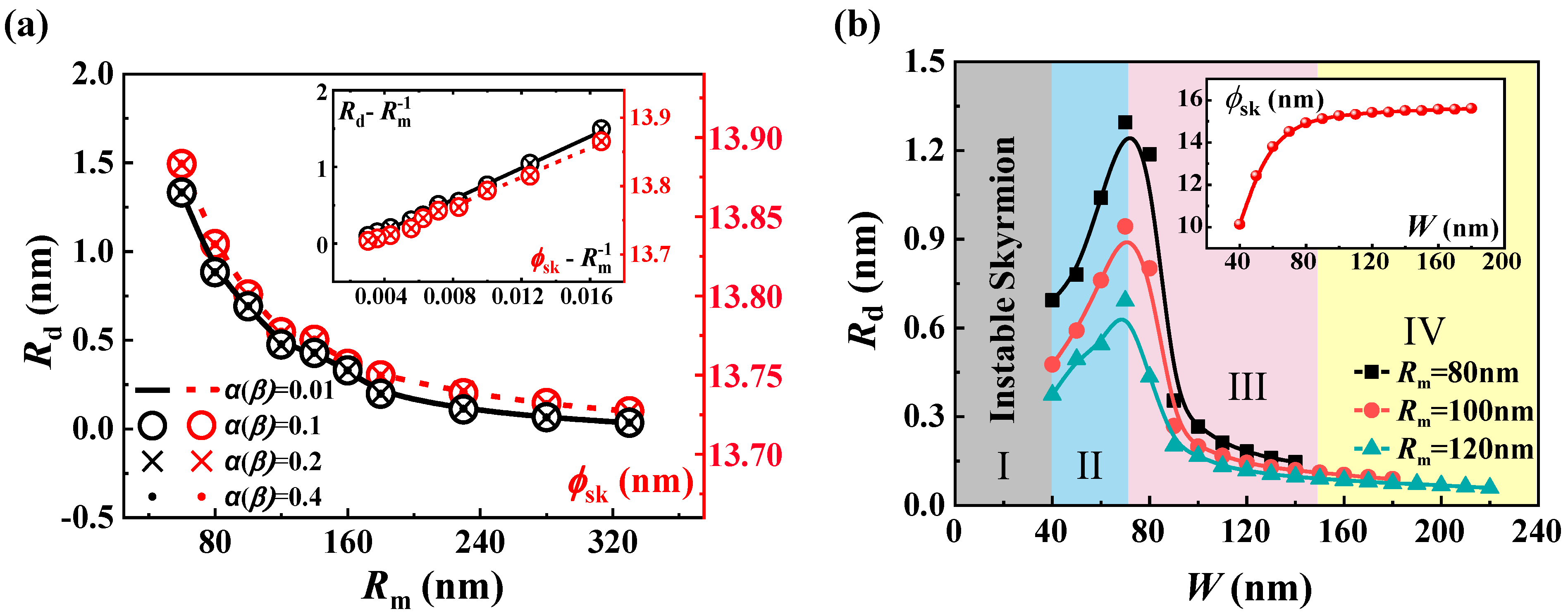
The SkHE caused by the asymmetry of the inner and outer boundaries is also reflected by the drift in the skyrmion’s stable position. To study this relationship, we calculated the initial drift distance Rd for different sizes of Rm of the circular-ring nanotrack under a range of values α ( β ) . The results presented in Figure 3a indicate that the skyrmion’s stable position tends to drift further away from the ring’s middle line as the circular ring becomes smaller. It can be observed from the inset of Figure 3a that the Rd is directly proportional to the curvature κ = R m 1 of the nanotrack, despite the values of α ( β ) being different. This is because the symmetry of the boundary is directly affected by the curvature of the circular ring. Additionally, both Figure 3a and the illustration in it show that the dependence of the skyrmion’s size ϕ sk (the red line) on the Rm is the same as that of Rd. The force from the asymmetric border essentially changes the size of the skyrmion and, hence, changes its stable position on the track.
In addition to the size Rm of the circular-ring nanotrack, the width also affects the force exerted by the boundary [40,50]. Figure 3b illustrates the drift distance Rd changes with the track’s width when the Rm is fixed at 80 nm, 100 nm, and 120 nm. Generally, it is still true that the smaller the Rm, the more obvious the skyrmion’s stable state drift from the middle line. However, for the same Rm values, the stable state can be divided into four regions at different width values, as shown in Figure 3b. In region I (0 < W < 40 nm), the tracks are too narrow for a stable skyrmion. In region II (40 < W < 70 nm), the presence of an asymmetric boundary leads to a reduction in the skyrmion’s size. However, the increase in width significantly increases the size of the skyrmion, causing Rd to gradually increase until the increase in width has little effect on the size of the skyrmion. When W > 70 nm, the skyrmion size does not increase significantly, so the Rd in regions III and IV is consistent with the effect of the circular ring size. For the larger W in region IV (W > 140 nm), the corresponding Rd ≤ 0.15 nm and the drift induced by the asymmetric boundary can be almost ignored. This is because as the track becomes wider, although the force caused by the asymmetric boundary still exists because the boundary is too far away from the skyrmion, the stable position will hardly move.
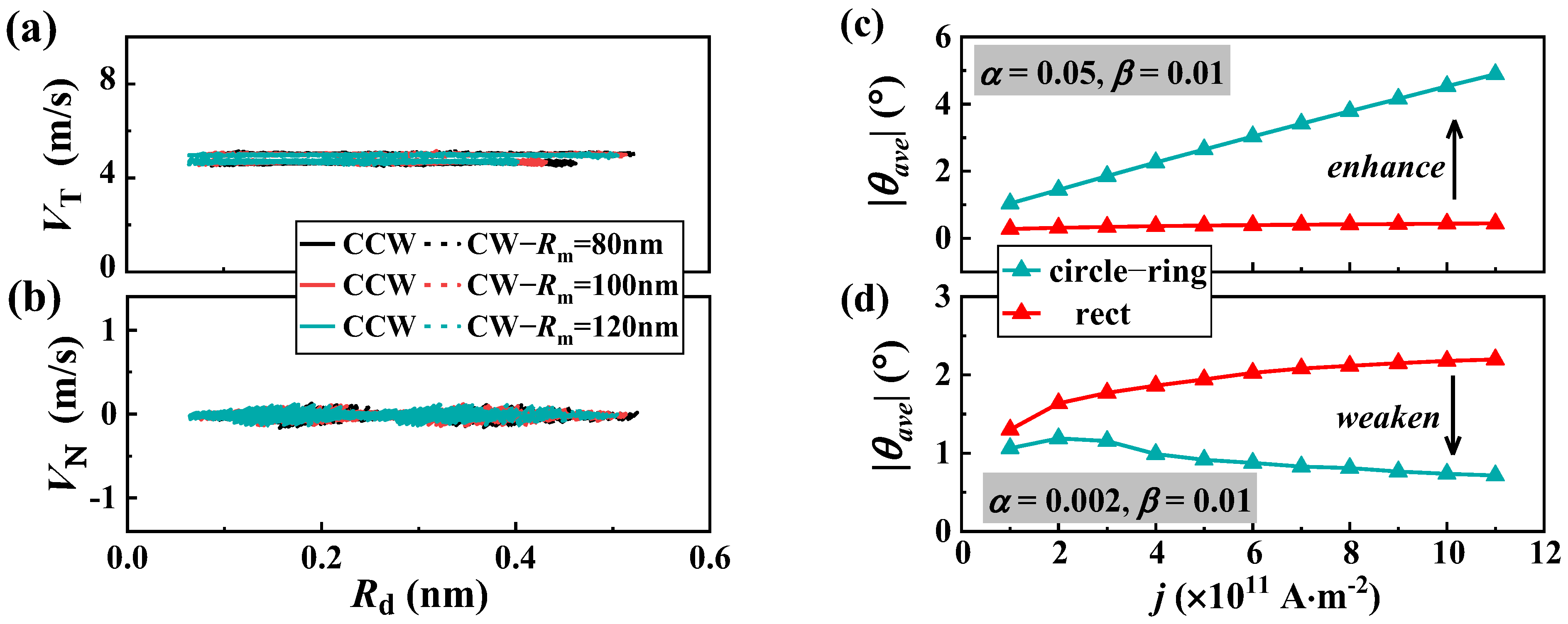
In order to confirm our analysis, we also calculated the skyrmion velocity on a wider nanotrack. Our findings revealed that as the track width widens, the periodic oscillation of VT (shown in Figure 1b) diminishes or disappears entirely, and the VN (depicted in Figure 1c) comes close to zero. To verify this, we tested a track width of W = 150 nm. As shown in Figure 4a,b, the VT no longer fluctuates significantly, but remains close to the velocity in the long straight track, and VN is also close to zero, as expected. The reason for this is that the boundary’s symmetry remains fixed for a given Rm, but the repulsive force from the boundary weakens as the track widens. This force is related to the skyrmion size and the distance from the boundary. As a result, the skyrmion is almost unaffected by the boundary.
Since the asymmetric boundaries of a circular ring can generate the SkHE, we have also studied the impact of asymmetric boundaries on the circular rings that already have the SkHE. As illustrated in Figure 4c,d, when α > β , the Hall angle in a circular-ring nanotrack is greater than that in a straight track, and the SkHE is enhanced. On the other hand, when α < β , the Hall angle in the circular-ring nanotrack is smaller than that in a straight track, and the SkHE is weakened. Therefore, the asymmetric boundaries can be used to strengthen or weaken the SkHE. This means that utilizing a circular-ring nanotrack offers a promising way to manipulate the SkHE in devices.
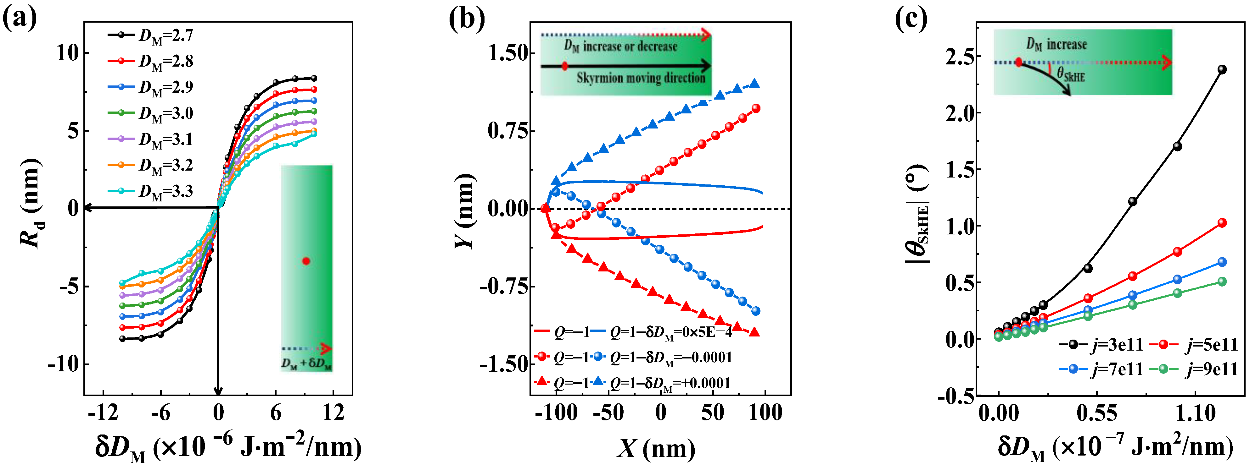
According to the research, the SkHE can also be induced by the inhomogeneous DMI [51]. In this section, we compared the effect of the asymmetric boundary with that of the inhomogeneous DMI. We created straight nanotracks with an inhomogeneous DMI, which had the same width as the circular-ring nanotrack. First, we compared the effect of non-uniform DMI on the skyrmion’s stable position with the circular ring. Figure 5a illustrates the relationship between the drifted distance of the skyrmion’s stable position and the DMI change values for different initial DMI values. When there was no change in DMI, the skyrmion stayed in the center of the track. However, even a slight change in DMI can cause the skyrmion to drift from the middle line. The 1.25 × 10 6   J m 2 / nm DMI gradient can cause a similar drift distance of the skyrmion’s stable position with the circular ring with Rm = 80 nm.
We also conducted an analysis to determine the factors that influence the Hall angle in tracks with the inhomogeneous DMI distribution. The trajectory of the skyrmion in the modeled nanotrack is shown in Figure 5b. It was observed that the presence of an inhomogeneous DMI distribution in the nanotrack causes the skyrmion to move toward the boundaries as it moves in the circular ring. Additionally, we found that the sign of the Hall angle depends on the sign of δ D M and skyrmion topological number Q. Figure 5c illustrates the relationship between the Hall angle and the value of the DMI changes for various current densities. Compared with the circular ring, the 1.1 × 10 7   J m 2 / nm DMI gradient can only yield a Hall angle of about 2 ° for the j = 3 . 0 × 10 3   A m 2 driving current. For high current density, a larger DMI gradient is required to cause a 2 ° Hall angle. Therefore, the SkHE caused by the circular ring is much more significant than that caused by the inhomogeneous DMI.

4. Conclusions

In conclusion, we investigated the current-driven skyrmion movement in circular-ring-shaped nanotracks. The results showed that the presence of an asymmetric boundary causes a shift in the skyrmion’s stable position, leading to an SkHE-like movement when driven by a current. We also noticed that the skyrmion velocity can be linearly changed by the SkHE induced by the asymmetric boundary of the circular-ring nanotrack. The asymmetric boundaries also have advantages in enhancing or weakening the skyrmion Hall effect. We also compared the SkHE from the asymmetric boundaries of circular-ring nanotracks with that from the inhomogeneous DMI. It was found that the SkHE caused by the circular ring is significantly greater than that caused by the inhomogeneous DMI. These findings not only contribute to our understanding of the skyrmion dynamics in confined geometries, but also provide an alternative approach to controlling the SkHE of skyrmion-based devices. Due to the significant impact of curved tracks on skyrmion motion, more interesting movement behaviors of single or multiple skyrmions can be expected in different shaped tracks such as disks, Corbino geometric rings, coupling rings, and elliptical rings. Changing the shape of the track is also expected to provide the possibility of the manipulation of the skyrmion velocity in devices.

Author Contributions

Conceptualization, N.C., Y.H. and Y.L.; methodology, N.C., Y.H. and Y.L.; software, N.C., X.Z., Y.H. and Y.L.; validation, N.C., Y.H. and Y.L.; formal analysis, N.C., Y.H. and Y.L.; investigation, N.C., Y.H. and Y.L.; resources, N.C., X.Z., Y.H. and Y.L.; writing—original draft, N.C., Y.H. and Y.L.; supervision, Y.H. and Y.L.; project administration, Y.H. and Y.L.; funding acquisition, Y.H. and Y.L. All authors have read and agreed to the published version of the manuscript.

Funding

This work was supported by the LiaoNing Revitalization Talents Program (Grant No. XLYC2007150) for Y.L., the Fundamental Research Funds for the Central Universities of the Ministry of Education of China (N2205015) for Y.L., and the National Natural Science Foundation of China (Grant No. 11774045) for Y.L.

Data Availability Statement

All of the data present in this paper will be made available upon reasonable request. Please contact the corresponding author for further information.

Conflicts of Interest

The authors declare no conflict of interest.

References

  1. Rossler, U.K.; Bogdanov, A.N.; Pfleiderer, C. Spontaneous skyrmion ground states in magnetic metals. Nature 2006, 442, 797. [Google Scholar] [CrossRef]
  2. Mühlbauer, S.; Binz, B.; Jonietz, F.; Pfleiderer, C.; Rosch, A.; Neubauer, A.; Georgii, R.; Böni, P. Skyrmion lattice in a chiral magnet. Science 2009, 323, 915. [Google Scholar] [CrossRef]
  3. Kravchuk, V.P.; Rossler, U.K.; Volkov, O.M.; Sheka, D.D.; van den Brink, J.; Makarov, D.; Fuchs, H.; Fangohr, H.; Gaididei, Y. Topologically stable magnetization states on a spherical shell: Curvature-stabilized skyrmions. Phys. Rev. B 2016, 94, 144402. [Google Scholar] [CrossRef]
  4. Castillo-Sepúlveda, S.; Vélez, J.A.; Corona, R.M.; Carvalho-Santos, V.L.; Laroze, D.; Altbir, D. Skyrmion dynamics in a double-disk geometry under an electric current. Nanomaterials 2022, 12, 3086. [Google Scholar] [CrossRef]
  5. Nagaosa, N.; Tokura, Y. Topological properties and dynamics of magnetic skyrmions. Nat. Nanotechnol. 2013, 8, 899. [Google Scholar] [CrossRef]
  6. Parkin, S.S.; Hayashi, M.; Thomas, L. Magnetic domain-wall racetrack memory. Science 2008, 320, 190. [Google Scholar] [CrossRef]
  7. Woo, S.; Litzius, K.; Kruger, B.; Im, M.Y.; Caretta, L.; Richter, K.; Mann, M.; Krone, A.; Reeve, R.M.; Weigand, M.; et al. Observation of room-temperature magnetic skyrmions and their current-driven dynamics in ultrathin metallic ferromagnets. Nat. Mater. 2016, 15, 501. [Google Scholar] [CrossRef]
  8. Boulle, O.; Vogel, J.; Yang, H.; Pizzini, S.; de Souza Chaves, D.; Locatelli, A.; Mentes, T.O.; Sala, A.; Buda-Prejbeanu, L.D.; Klein, O.; et al. Room-temperature chiral magnetic skyrmions in ultrathin magnetic nanostructures. Nat. Nanotechnol. 2016, 11, 449. [Google Scholar] [CrossRef]
  9. Yu, G.; Upadhyaya, P.; Li, X.; Li, W.; Kim, S.K.; Fan, Y.; Wong, K.L.; Tserkovnyak, Y.; Amiri, P.K.; Wang, K.L. Room-temperature creation and spin-orbit torque manipulation of skyrmions in thin films with engineered asymmetry. Nano Lett. 2016, 16, 1981. [Google Scholar] [CrossRef]
  10. Yu, G.; Jenkins, A.; Ma, X.; Razavi, S.A.; He, C.; Yin, G.; Shao, Q.; He, Q.L.; Wu, H.; Li, W.; et al. Room-temperature skyrmions in an antiferromagnet-based heterostructure. Nano Lett. 2018, 18, 980. [Google Scholar] [CrossRef]
  11. Jonietz, F.; Mühlbauer, S.; Pfleiderer, C.; Neubauer, A.; Munzer, W.; Bauer, A.; Adams, T.; Georgii, R.; Boni, P.; Duine, R.A.; et al. Spin transfer torques in MnSi at ultralow current densities. Science 2010, 330, 1648. [Google Scholar] [CrossRef]
  12. Fert, A.; Cros, V.; Sampaio, J. Skyrmions on the track. Nat. Nanotechnol. 2013, 8, 152. [Google Scholar] [CrossRef]
  13. Yu, X.Z.; Kanazawa, N.; Zhang, W.Z.; Nagai, T.; Hara, T.; Kimoto, K.; Matsui, Y.; Onose, Y.; Tokura, Y. Skyrmion flow near room temperature in an ultralow current density. Nat. Commun. 2012, 3, 988. [Google Scholar] [CrossRef]
  14. Lin, J.-Q.; Chen, J.-P.; Tan, Z.-Y.; Chen, Y.; Chen, Z.-F.; Li, W.-A.; Gao, X.-S.; Liu, J.-M. Manipulation of skyrmion motion dynamics for logical device application mediated by inhomogeneous magnetic anisotropy. Nanomaterials 2022, 12, 278. [Google Scholar] [CrossRef]
  15. Chen, G. Skyrmion Hall effect. Nat. Phys. 2017, 13, 112. [Google Scholar] [CrossRef]
  16. Göbel, B.; Mertig, I. Skyrmion ratchet propagation: Utilizing the skyrmion Hall effect in AC racetrack storage devices. Sci. Rep. 2021, 11, 3020. [Google Scholar] [CrossRef]
  17. Vizarim, N.P.; Reichhardt, C.; Venegas, P.A.; Reichhardt, C.J.O. Guided skyrmion motion along pinning array interfaces. J. Magn. Magn. Mater. 2021, 528, 167710. [Google Scholar] [CrossRef]
  18. Shigenaga, T.; Leonov, A.O. Harnessing skyrmion Hall effect by thickness gradients in wedge-shaped samples of cubic helimagnets. Nanomaterials 2023, 13, 2073. [Google Scholar] [CrossRef]
  19. Guo, J.; Hou, Y.; Zhang, X.; Pong, P.W.T.; Zhou, Y. Elimination of the skyrmion Hall effect by tuning perpendicular magnetic anisotropy and spin polarization angle. Phys. Lett. A 2022, 456, 128497. [Google Scholar] [CrossRef]
  20. Hong, I.S.; Lee, K.J. Magnetic skyrmion field-effect transistors. Appl. Phys. Lett. 2019, 115, 072406. [Google Scholar] [CrossRef]
  21. Zhou, L.; Qin, R.; Zheng, Y.-Q.; Wang, Y. Skyrmion Hall effect with spatially modulated Dzyaloshinskii–Moriya interaction. Front. Phys. 2019, 14, 536021. [Google Scholar] [CrossRef]
  22. Tan, A.K.C.; Ho, P.; Lourembam, J.; Huang, L.; Tan, H.K.; Reichhardt, C.J.O.; Reichhardt, C.; Soumyanarayanan, A. Visualizing the strongly reshaped skyrmion Hall effect in multilayer wire devices. Nat. Commun. 2021, 12, 4252. [Google Scholar] [CrossRef]
  23. Souza, J.C.B.; Vizarim, N.P.; Reichhardt, C.J.O.; Reichhardt, C.; Venegas, P.A. Skyrmion ratchet in funnel geometries. Phys. Rev. B 2021, 104, 054434. [Google Scholar] [CrossRef]
  24. Feng, Y.; Zhang, X.; Zhao, G.; Xiang, G. A skyrmion diode based on skyrmion Hall effect. IEEE Trans. Electron. Devices 2022, 69, 1293. [Google Scholar] [CrossRef]
  25. Song, C.; Zhao, L.; Liu, J.; Jiang, W. Experimental realization of a skyrmion circulator. Nano Lett. 2022, 22, 9638. [Google Scholar] [CrossRef]
  26. Bellizotti Souza, J.C.; Vizarim, N.P.; Reichhardt, C.J.O.; Reichhardt, C.; Venegas, P.A. Magnus induced diode effect for skyrmions in channels with periodic potentials. J. Phys. Condens. Matter 2022, 35, 015804. [Google Scholar] [CrossRef]
  27. Whang, H.S.; Choe, S.B. Spin-Hall-effect-modulation skyrmion oscillator. Sci. Rep. 2020, 10, 11977. [Google Scholar] [CrossRef]
  28. Wang, J.; Xia, J.; Zhang, X.; Zheng, X.; Li, G.; Chen, L.; Zhou, Y.; Wu, J.; Yin, H.; Chantrell, R.; et al. Magnetic skyrmionium diode with a magnetic anisotropy voltage gating. Appl. Phys. Lett. 2020, 117, 202401. [Google Scholar] [CrossRef]
  29. Bellizotti Souza, J.C.; Vizarim, N.P.; Reichhardt, C.J.O.; Reichhardt, C.; Venegas, P.A. Clogging, diode and collective effects of skyrmions in funnel geometries. New J. Phys. 2022, 24, 103030. [Google Scholar] [CrossRef]
  30. Castell-Queralt, J.; González-Gómez, L.; Del-Valle, N.; Sanchez, A.; Navau, C. Accelerating, guiding, and compressing skyrmions by defect rails. Nanoscale 2019, 11, 12589. [Google Scholar] [CrossRef]
  31. Zhang, H.Y.; Zhu, D.Q.; Kang, W.; Zhang, Y.G.; Zhao, W.S. Stochastic computing implemented by skyrmionic logic devices. Phys. Rev. Appl. 2020, 13, 054049. [Google Scholar] [CrossRef]
  32. Paikaray, B.; Kuchibhotla, M.; Haldar, A.; Murapaka, C. Skyrmion based majority logic gate by voltage controlled magnetic anisotropy in a nanomagnetic device. Nanotechnology 2023, 34, 225202. [Google Scholar] [CrossRef] [PubMed]
  33. Shu, Y.; Li, Q.; Xia, J.; Lai, P.; Hou, Z.; Zhao, Y.; Zhang, D.; Zhou, Y.; Liu, X.; Zhao, G. Realization of the skyrmionic logic gates and diodes in the same racetrack with enhanced and modified edges. Appl. Phys. Lett. 2022, 121, 042402. [Google Scholar] [CrossRef]
  34. Yoo, M.-W.; Cros, V.; Kim, J.-V. Current-driven skyrmion expulsion from magnetic nanostrips. Phys. Rev. B 2017, 95, 184423. [Google Scholar] [CrossRef]
  35. Jung, D.-H.; Han, H.-S.; Kim, N.; Kim, G.; Jeong, S.; Lee, S.; Kang, M.; Im, M.-Y.; Lee, K.-S. Magnetic skyrmion diode: Unidirectional skyrmion motion via symmetry breaking of potential energy barriers. Phys. Rev. B 2021, 104, L060408. [Google Scholar] [CrossRef]
  36. Leonov, A.O.; Loudon, J.C.; Bogdanov, A.N. Spintronics via non-axisymmetric chiral skyrmions. Appl. Phys. Lett. 2016, 109, 172404. [Google Scholar] [CrossRef]
  37. Leonov, A.O.; Mostovoy, M. Edge states and skyrmion dynamics in nanostripes of frustrated magnets. Nat. Commun. 2017, 8, 14394. [Google Scholar] [CrossRef]
  38. Al Saidi, W.; Sbiaa, R.; Bhatti, S.; Piramanayagam, S.N.; Al Risi, S. Dynamics of interacting skyrmions in magnetic nano-track. J. Phys. D Appl. Phys. 2023, 56, 355001. [Google Scholar] [CrossRef]
  39. Morshed, M.G.; Vakili, H.; Ghosh, A.W. Positional stability of skyrmions in a racetrack memory with notched geometry. Phys. Rev. Appl. 2022, 17, 064019. [Google Scholar] [CrossRef]
  40. Zhang, X.; Zhao, G.P.; Fangohr, H.; Liu, J.P.; Xia, W.X.; Xia, J.; Morvan, F.J. Skyrmion-skyrmion and skyrmion-edge repulsions in skyrmion-based racetrack memory. Sci. Rep. 2015, 5, 7643. [Google Scholar] [CrossRef]
  41. Gaididei, Y.; Kravchuk, V.P.; Sheka, D.D. Curvature effects in thin magnetic shells. Phys. Rev. Lett. 2014, 112, 257203. [Google Scholar] [CrossRef] [PubMed]
  42. Streubel, R.; Fischer, P.; Kronast, F.; Kravchuk, V.P.; Sheka, D.D.; Gaididei, Y.; Schmidt, O.G.; Makarov, D. Magnetism in curved geometries. J. Phys. D Appl. Phys. 2016, 49, 363001. [Google Scholar] [CrossRef]
  43. Vansteenkiste, A.; Leliaert, J.; Dvornik, M.; Helsen, M.; Garcia-Sanchez, F.; Van Waeyenberge, B. The design and verification of MuMax3. AIP. Adv. 2014, 4, 107133. [Google Scholar] [CrossRef]
  44. Leliaert, J.; Dvornik, M.; Mulkers, J.; De Clercq, J.; Milošević, M.V.; Van Waeyenberge, B. Fast micromagnetic simulations on GPU—Recent advances made with MuMax3. J. Phys. D Appl. Phys. 2018, 51, 123002. [Google Scholar] [CrossRef]
  45. Leonov, A.O.; Monchesky, T.L.; Romming, N.; Kubetzka, A.; Bogdanov, A.N.; Wiesendanger, R. The properties of isolated chiral skyrmions in thin magnetic films. New J. Phys. 2016, 18, 065003. [Google Scholar] [CrossRef]
  46. Je, S.G.; Thian, D.; Chen, X.; Huang, L.; Jung, D.H.; Chao, W.; Lee, K.S.; Hong, J.I.; Soumyanarayanan, A.; Im, M.Y. Targeted writing and deleting of magnetic skyrmions in two-terminal nanowire devices. Nano Lett. 2021, 21, 1253. [Google Scholar] [CrossRef]
  47. Ma, C.; Zhang, X.; Xia, J.; Ezawa, M.; Jiang, W.; Ono, T.; Piramanayagam, S.N.; Morisako, A.; Zhou, Y.; Liu, X. Electric field-Iinduced creation and directional motion of domain walls and skyrmion bubbles. Nano Lett. 2018, 19, 353. [Google Scholar] [CrossRef]
  48. Zhang, X.C.; Xia, J.; Zhao, G.P.; Liu, X.X.; Zhou, Y. Magnetic skyrmion transport in a nanotrack with spatially varying damping and non-adiabatic torque. IEEE Trans. Magn. 2017, 53, 1500206. [Google Scholar] [CrossRef]
  49. Metlov, K.L. Topological memory with multiply-connected planar magnetic nanoelements. JETP Lett. 2023, 118, 105. [Google Scholar] [CrossRef]
  50. Chen, X.; Kang, W.; Zhu, D.; Zhang, X.; Lei, N.; Zhang, Y.; Zhou, Y.; Zhao, W. Skyrmion dynamics in width-varying nanotracks and implications for skyrmionic applications. Appl. Phys. Lett. 2017, 111, 202406. [Google Scholar] [CrossRef]
  51. Gorshkov, I.O.; Gorev, R.V.; Sapozhnikov, M.V.; Udalov, O.G. DMI-gradient-driven skyrmion motion. ACS Appl. Electron. Mater. 2022, 4, 3205. [Google Scholar] [CrossRef]
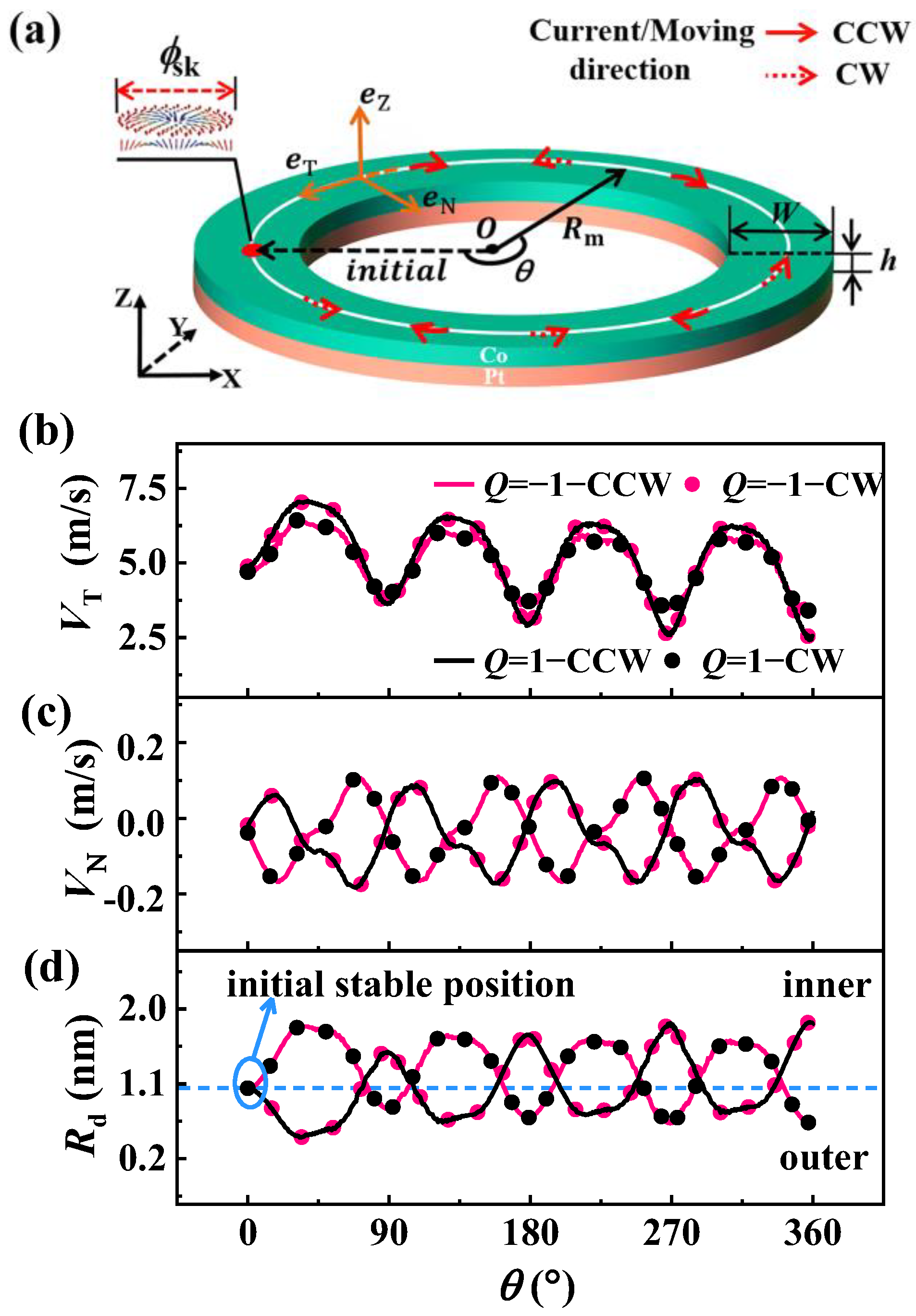
Figure 1. Model and skyrmion dynamics. (a) The schematic of the circular-ring nanotrack, where θ represents the angular parameter of the skyrmion at different positions, and Rm is the middle line radius of the tracks. The red arrows represent the clockwise (CCW) and counterclockwise (CW) driving current (moving) directions, respectively. (b) The parallel velocity VT, perpendicular velocity VN (c), and the drift distance of the initial stable position (d) as functions of the position parameter θ. Q represents the topological number of skyrmion.
Nanomaterials 13 02977 g001
Figure 2. Skyrmion dynamics in the circular ring. (a) The skyrmion Hall angle as a function of the position parameter θ. The gray part shows the trajectories of the skyrmion under the conventional skyrmion Hall effect for the case α < β . (b) The function between VT and the drift distance Rd for different middle line radius Rm values. Unless otherwise specified, the simulations were carried out under the fixed width W = 60 nm and the applied current density j = 1 × 10 11   A m 2 .
Nanomaterials 13 02977 g002
Figure 3. Analysis of skyrmion dynamics. (a) The drift distance Rd (black line) and the size of the skyrmion ϕ sk (red line) as functions of the middle line radius Rm for the cases of no current and different α ( β ) values. (b) The drift distance Rd as a function of track width W, where the Rm is fixed at 80 nm, 100 nm, and 120 nm, respectively. Unstable region I, width-dominant region II, asymmetric-boundary-dominant region III, low response region IV.
Nanomaterials 13 02977 g003
Figure 4. Verification of the skyrmion dynamics. The skyrmion velocity’s (a) parallel velocity VT and (b) perpendicular velocity VN as functions of its position parameter θ with different middle line radius Rm; the width is fixed at 150 nm. The average values of the Hall angle as functions of the current density in circular-ring nanotrack and straight track for the cases of (c) α > β and (d) α < β .
Nanomaterials 13 02977 g004
Figure 5. Skyrmion dynamics in an inhomogeneous DMI distribution nanotrack. (a) The drift distance Rd as a function of the DMI change value in long straight tracks for different initial DMI values. (b) Skyrmion motion trajectory driven by the current in the modeled nanotrack, with the modeled track with an inhomogeneous DMI distribution in the long direction. (c) The Hall angle as a function of the DMI change value in the modeled nanotrack.
Nanomaterials 13 02977 g005
Disclaimer/Publisher’s Note: The statements, opinions and data contained in all publications are solely those of the individual author(s) and contributor(s) and not of MDPI and/or the editor(s). MDPI and/or the editor(s) disclaim responsibility for any injury to people or property resulting from any ideas, methods, instructions or products referred to in the content.