Article

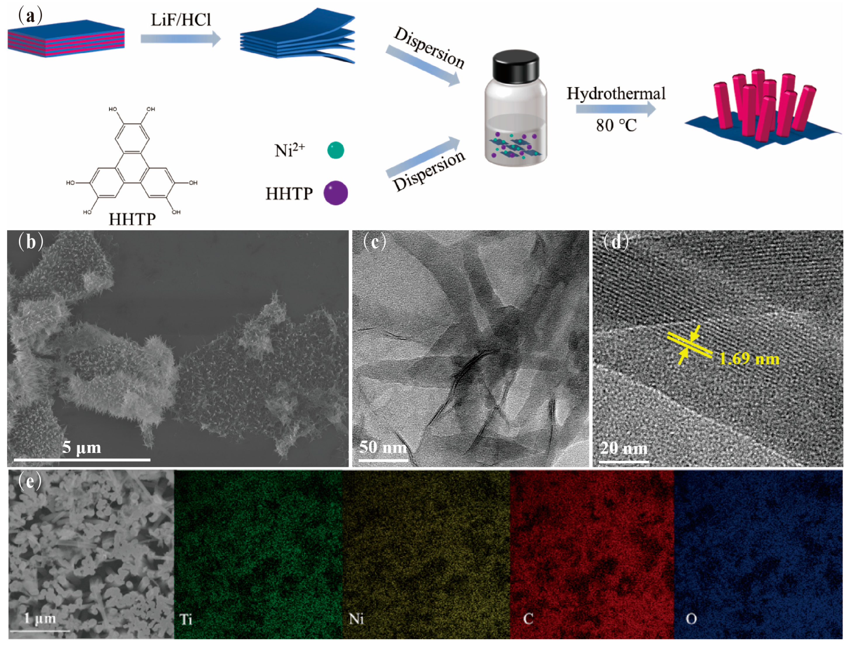
In Situ Growth of Ni-MOF Nanorods Array on Ti3C2Tx Nanosheets for Supercapacitive Electrodes

1
NEST Lab, Department of Chemistry, College of Sciences, Shanghai University, Shanghai 200444, China
2
i-Lab, Nano-X Vacuum Interconnected Workstation, Key Laboratory of Multifunction Nanomaterials and Smart Systems, Suzhou Institute of Nano-Tech and Nano-Bionics (SINANO), Chinese Academy of Sciences (CAS), 398 Ruoshui Road, Suzhou 215123, China
3
Gusu Lab for Advanced Materials, Suzhou 215123, China
*
Authors to whom correspondence should be addressed.
Nanomaterials 2023, 13(3), 610; https://doi.org/10.3390/nano13030610
Submission received: 31 December 2022 / Revised: 30 January 2023 / Accepted: 31 January 2023 / Published: 3 February 2023
(This article belongs to the Section Nanocomposite Materials)

Abstract

:
For the energy supply of smart and portable equipment, high performance supercapacitor electrode materials are drawing more and more concerns. Conductive Ni-MOF is a class of materials with higher conductivity compared with traditional MOFs, but it continues to lack stability. Specifically, MXene (Ti3C2Tx) has been employed as an electrochemical substrate for its high mechanical stability and abundant active sites, which can be combined with MOFs to improve its electrochemical performance. In this paper, a novel Ni-MOF nanorods array/Ti3C2Tx nanocomposite was prepared via a facile hydrothermal reaction, which makes good use of the advantages of conductive Ni-MOF and high strength Ti3C2Tx. The high density forest-like Ni-MOF array in situ grown on the surface of Ti3C2Tx can provide abundant active electrochemical sites and construct a pathway for effective ion transport. The formation of a “Ti-O···Ni” bond accomplished during an in situ growth reaction endows the strong interfacial interaction between Ni-MOF and Ti3C2Tx. As a result, the Ni-MOF/Ti3C2Tx nanocomposite can achieve a high specific capacitance of 497.6 F·g−1 at 0.5 A·g−1 and remain over 66% of the initial capacitance when the current density increases five times. In addition, the influence of the Ti3C2Tx concentration and reaction time on the morphology and performance of the resultant products were also investigated, leading to a good understanding of the formation process of the nanocomposite and the electrochemical mechanism for a supercapacitive reaction.

1. Introduction

Energy supplement devices with ultrathin volume, high energy density, and long lifespan are arousing amounts of interest along with the miniaturization and portability of smart equipment [1,2,3]. Among them, high performance supercapacitors have propelled rapidly because of their fast charge/discharge speed, convenient assembly, and high-level safety regardless of if the miniaturization process is performed [4,5,6]. However, further progress is severely constrained by their low energy density. Thus, it is necessary to investigate novel electrode materials with superior conductivity, high specific surface area, and easy preparation to overcome this restriction [7,8,9].
Metal-organic frameworks (MOFs) have been widely focused on in the past decades because of their considerable specific surface area, tunable structural architectures, and abundant active sites [10,11,12]. Formerly, the low conductivity limits traditional MOFs’ appearance in a number of current advanced technologies with the requirement of high electrical conductivity. With the appearance of conductive MOFs such as M-HHTP (M is Co, Ni, Cu, etc. and HHTP is hexahydroxytriphenylene) [13,14], they gradually exhibit greater potential in supercapacitors [15,16]. For instance, Mircea et al. reported the first example of a supercapacitor electrode made entirely from neat conductive MOFs as active materials [17]. However, the improved conductivity is still restricted by the shortages of low specific capacitances and structural stability in the long-term cycling process. Therefore, other conductive matrixes including conductive polymers (e.g., polypyrrole or polyaniline) and carbon-based materials (e.g., graphene or carbon nanotubes) have been brought into compositing with MOF to guarantee the effective control on electrochemical performances [18,19,20,21,22,23].
Mn+1XnTx (n = 1~4), in which M represents transition metals (e.g., Ti, V, etc.), X is C or/and N, and Tx stands for terminal groups, such as -O, -OH, and -F, on the surface [24,25], and also named MXene, has been developed quickly since it has excellent conductivity [26,27], many surface groups for functional modification [28,29], and other fascinating tunable properties [30,31]. Recently, Ti3C2Tx, the most widely studied MXene, has been used in supercapacitors by diversiform-processing techniques [32,33,34]. Nevertheless, there are also shortcomings in the easy stacking and oxidization of Ti3C2Tx nanosheets during the electrochemical reaction process, which can be remitted by modifying them with other active materials [35,36].
Herein, combined with the above merits of MOFs, it can be clearly suggested that the nanocomposite synthesized from Ti3C2Tx and conductive Ni-MOF will effectively make the utmost of their advantages since MXenes improve composite conductivity and provide sufficient surface groups to interact with MOFs while the Ni-MOF plays an important role in offering plentiful active sites and large specific surface area, reasonably obtaining incremental attention in electrochemical applications [37,38,39]. However, the direct combination out of in situ growth provides weak interfacial bonding, which can result in high transport impedance and low cyclic stability. In addition, the relationship between structural architectures and electrochemical performances is also unrevealed through regulating reaction conditions. Briefly, there is a significant attempt to develop MXene-MOF nanocomposites to solve the above issues on the account of the in situ growth strategy.
In this study, we propose a strategy for the in situ growing of forest-like hexagonal-shaped Ni-MOF (Ni-HHTP) directly on the surface of Ti3C2Tx rather than the simple mixture. The advantages of Ti3C2Tx and Ni-MOF are effectively combined in this nanocomposite to address the aforementioned shortcomings, enabling reversible transport of electrons and ions at the interface as well as preventing the collapse of porous MOF structures during the insertion and de-intercalation of electrolyte ions. Additionally, the in situ growth mechanism of this nanocomposite was studied through analyzing the morphology and structure of serial products prepared from the controlled factors of reactant concentration and reaction time. Moreover, the electrochemical characterizations reveal that the Ni-MOF/Ti3C2Tx nanocomposite exhibits a high specific capacitance value of 497.6 F·g−1 (0.5 A·g−1) with a high cyclic stability of 85% during 1000 cycles, which can be due to the synergistic effect of the underlying MXene substrate and porous MOF architectures. Furthermore, an all-solid-state asymmetric supercapacitor was also demonstrated by exploiting the Ni-MOF/Ti3C2Tx nanocomposite as a positive-electrode material, successful in lighting a LED. The obtained results will possess great potential for electrochemical devices.

2. Materials and Methods

2.1. Synthesis of MXene Ti3C2Tx

As the most reported method [40], Ti3C2Tx nanosheet was synthesized as follows: 8 g of LiF was added to 100 mL of 9 M HCl in a PTFE bottle as the etchant. A total of 5 g Ti3AlC2 was slowly added to the above etchant in an ice bath. The reaction was heated under 40 °C and magnetic stirring was maintained for 24 h. A dark green Ti3C2Tx slurry was formed after washing by deionization water via centrifugation at 3500 rpm for 5 min until the pH reached 5~6. The Ti3C2Tx powder was collected through centrifugating the slurry at 12,000 rpm for 30 min and drying the sediment at 80 °C in a vacuum oven for 24 h.

2.2. Synthesis of Ni-MOF/Ti3C2Tx

The Ni-MOF/Ti3C2Tx nanocomposite was synthesized as follows: 0.5 mg/mL of Ti3C2Tx solution was prepared under ultrasonication for 30 min. An amount of 40 mg Ni(OAc)2∙4H2O and 28 mg HHTP was dispersed in 4 mL deionized water, respectively, before mixing the two homogeneous solutions above. Then, 8 mL mixture was added to 8 mL Ti3C2Tx solution in a 20 mL vessel. The reaction was heated in an oven at 80 °C for 8 h and then cooled down to room temperature within 3 h. Black sediment was collected at the bottom of the vessel. The Ni-MOF/Ti3C2Tx sample was obtained by washing the sediment using deionized water and ethanol for several times. The length of Ni-MOF nanorods in situ grown on the Ti3C2Tx nanosheet was efficiently controlled by the hydrothermal reaction time. The pure Ni-MOF powder was synthesized through the same procedure without Ti3C2Tx.

2.3. Activation of Ni-MOF/Ti3C2Tx

The Ni-MOF/Ti3C2Tx powder was activated after immersing it into deionized water at 80 °C overnight and exchanging the solvent with acetone that was replaced everyday for three days. The acetone-exchanged Ni-MOF/Ti3C2Tx powder was collected after drying at 80 °C in a vacuum oven for 24 h to remove guest molecules.

2.4. Fabrication of the Electrodes in a Traditional Three-Electrode System

Electrochemical performance was conducted by a CHI 660E workstation in a three-electrode system. A platinum wire electrode and a Hg/HgO electrode was used as the counter electrode and reference electrode, respectively. A concentration of 6.0 M KOH was chosen as the electrolyte. The working electrode was prepared by the mixing active materials, acetylene black and polytetrafluoroethylene (PTFE), with a weight ratio of 8:1:1, and then coating the mixture above on a 1 cm × 3 cm nickel foam. N-methyl-2-pyrrolidone was chosen as the additive when mixing and the coating area was about 1 cm2. Then, a thin foil was achieved by pressing the nickel foam under 10.0 MPa. The mass-loading of the active material was about 3–5 mg.

2.5. Fabrication of the Asymmetric Supercapacitor

The Ni-MOF/Ti3C2Tx nanocomposite and the active carbon were used as the positive and negative electrode materials, respectively. The mass ratio of electrode materials is determined by C+m+ = Cm, where C+ and C are the specific capacitance of Ni-MOF/Ti3C2Tx and active carbon. The KOH/PVA solution was used as the electrolyte and then sandwiched by the electrode. Lastly, the flexible supercapacitor was packeted with PET membrane. The resulting electrochemical measurement was conducted via a CHI 660E workstation.

3. Results and Discussion

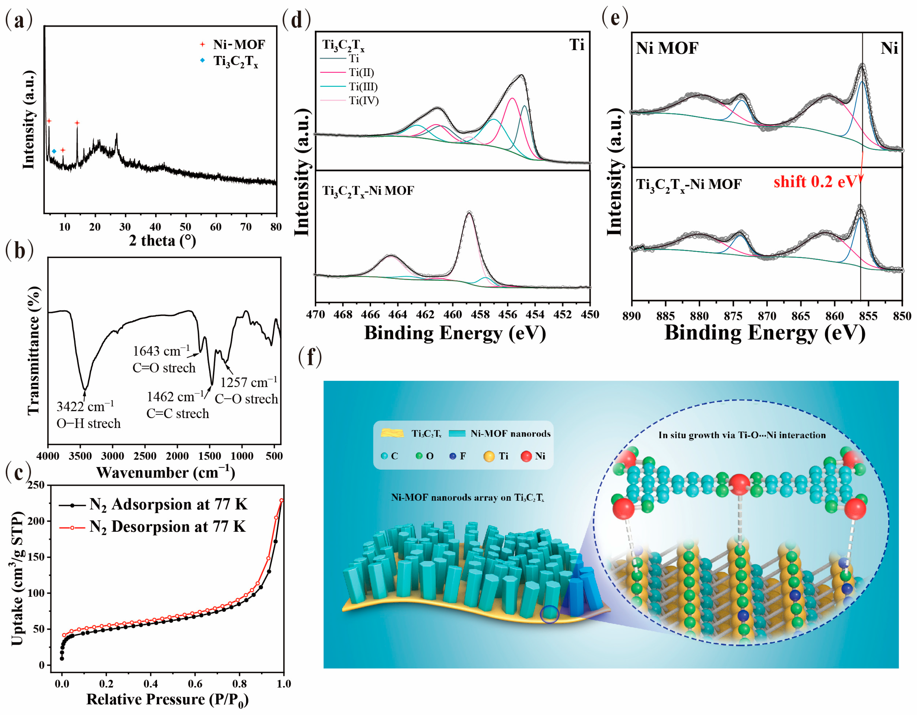
3.1. Sample Preparation and Structure Characterization

The schematic diagram of the synthesis procedure of the Ni-MOF/Ti3C2Tx nanocomposite is depicted in Figure 1a. Initially, the Ti3C2Tx solution was prepared from its corresponding nanosheet powder that was obtained through etching the Al layers using LiF/HCl and dried in a vacuum; the two-dimensional Ti3C2Tx nanosheets’ morphology is shown in Figure S1. Next, a homogeneous precursor mixture was obtained by adding Ni(OAc)2∙4H2O and HHTP into the above Ti3C2Tx solution, which was subsequently put in an 80 °C oven for a hydrothermal reaction. Lastly, the expected Ni-MOF/Ti3C2Tx sample was received via washing the collected reaction sediment with DI water and ethyl alcohol repeatedly. Afterwards, the controlled products prepared from the various reactant concentrations and hydrothermal times were employed to investigate the in situ growth mechanism and electrochemical performance of the nanocomposite.
The morphology of the as-prepared Ni-MOF/Ti3C2Tx nanocomposite (0.5 mg∙mL−1 and 12 h) was revealed using the images from scanning electron microscopy (SEM), as shown in Figure 1b. It can be seen that the regular forest-like Ni-MOF nanorod arrays with hexagonal architectures and lengths of up to 550 nm were grown in situ on the surface of Ti3C2Tx, vertically, forming strong interfacial bonds, which can bring about low electrochemical impedance and high cyclic stability for this well-designed nanocomposite. In addition, there was no obvious stacking phenomenon of the 2D Ti3C2Tx nanosheets since the in situ growth of the Ni-MOF arrays can also effectively prevent the agglomeration of lamellae that occurred in the hydrothermal process. Furthermore, the elemental mapping of this Ni-MOF/Ti3C2Tx nanocomposite given by the energy dispersive spectrometer (EDS) also demonstrates the uniform in situ growth of the Ni-MOF arrays arranged on the surface of the Ti3C2Tx nanosheets, as consistent with the above SEM results (Figure 1e). This leads to abundant active sites for redox reactions and effective transport pathways for electron transfer and ion diffusion, which makes a great contribution to enhance the electrochemical properties of this novel Ni-MOF/Ti3C2Tx nanocomposite.
Furthermore, the nature of the crystal structure of the as-synthesized Ni-MOF/Ti3C2Tx products was characterized by transmission electron microscopy (TEM) (Figure 1c). It can be evidently seen in Figure 1c that the nanocomposite consists of numerous Ni-MOF nanorods in situ forming on the surface of the 2D Ti3C2Tx nanosheets, which is in agreement with the above SEM observations. Additionally, the apparent wrinkles of the 2D nanosheets and the whole forest-like constructions implicitly exhibit the Ni-MOF/Ti3C2Tx sample endowed with steady and strong interfacial bonding because there is no obvious crack or collapse occurring even after ultrasonication treatment. The high resolution TEM (HRTEM) (Figure 1d) reveals that the characteristic lattice fringe of 1.69 nm belongs to the (100) crystal face of the Ni-MOF structure.
As shown in Figure 2a, according to previous studies, the characteristic diffraction peaks of the Ni-MOF/Ti3C2Tx nanocomposites at 2θ of 4.8°, 9.7°, and 14.2° are attributed to the (100), (200), and (210) lattice planes of Ni-MOF [41], respectively, suggesting a high crystallinity of the products. Furthermore, compared with the peaks of the mixture of Ni-MOF and Ti3C2T (Figure S1), the location of the (002) plane shifts from 6.6° to approximately 6.2° and the intensity decreases to near disappearance, demonstrating that the (100) face of Ni-MOF nanorods were grown in situ on the (002) face of the Ti3C2Tx nanosheets rather than simply mixture [42]. It can also be inferred that there was no stacking of Ti3C2Tx nanosheets from the pattern in which more electrolyte anions can be contained and serve as electroactive species in the Faradaic redox reaction.
Fourier transform-infrared (FT-IR) measurements were performed to confirm the interactions between the components of Ti3C2Tx and Ni-MOF based on the location changes of the functional groups in the Ni-MOF/Ti3C2Tx nanocomposite. As shown in Figure 2b, the spectrum of nanocomposite exhibits the typical absorption features of its above components containing the stretching mode of the O-H group at 3422 cm−1, the C=O group at 1643 cm−1, graphene at 1462 cm−1, and the C-O group at 1257 cm−1, which can be observed from Ti3C2Tx and Ni-MOF in Figure S2 [41]. It is known that the O-H stretching vibration peak can evidently appear red-shift when the interactions take place from the molecular level. It is noted in Figure S2 that the O-H stretching vibration peak at 3422 cm−1 for the Ni-MOF/Ti3C2Tx sample shows a certain red-shift compared with that at 3441 cm−1 for Ti3C2Tx, indicating there exists strong interactions between Ni-MOF and Ti3C2Tx, as consistent with the XRD results.
As exhibited in Figure 2c, the Brunauer–Emment–Teller (BET) test of the Ni-MOF/Ti3C2Tx nanocomposite gains a specific surface area of 167.74 m2∙g−1 and an average pore width of 14.3 nm. A type I isotherm profile demonstrates its microporous nature. All of these confirm its relatively large specific surface area by virtue of the well-defined forest-like nanorod arrays with a hierarchically hexagonal configuration, which is beneficial for enhancing the electrochemical properties.
Furthermore, X-ray photoelectron spectroscopy (XPS) was performed to illustrate the specific interaction sites of the above FT-IR analysis via characterizing the changes of the composition and the valence state of the elements between the Ni-MOF, Ti3C2Tx, and Ni-MOF/Ti3C2Tx nanocomposites. The fitting spectra of Ti 2p, Ni 2p, and O 1s of the Ni-MOF/Ti3C2Tx sample were detected, which demonstrate a high degree of interaction achieved between Ti3C2Tx and Ni-MOF (Figure S4). As shown in Figure 2e, the Ni 2p3/2 and 2p1/2 peaks of the nanocomposite (855.9 eV and 873.6 eV, respectively) show a definite change (0.2 eV shifting) compared with those of Ni-MOF (856.1 eV and 873.8 eV, respectively), revealing the formation of the “Ti-O···Ni” interaction between Ni-MOF and Ti3C2Tx as similar to the formation mechanism of “V-O···Ni”, as previously reported [39]. Furthermore, the Ti 2p spectra provide fairly powerful evidence to confirm the in situ growth mechanism of the nanocomposite as depicted in Figure 2d. It can be evidently found that the three doublets of the Ti 2p spectra of the Ni-MOF/Ti3C2Tx products present a majority of Ti4+ (458.8/464.4 eV) and few of Ti2+ (456.1/461.1 eV) and Ti3+ (457.6/463.2 eV), which are much different from the eight deconvoluted peaks of Ti (454.7 eV/460.7 eV), Ti2+ (455.6 eV461.1 eV), Ti3+ (456.7 eV/462.5 eV), and Ti4+ (458.8 eV/464.4 eV) of the pure Ti3C2Tx nanosheets. In addition, the Ti4+ in the nanocomposite turns out not to be in the form of TiO2, which can be proved by no obvious TiO2 characteristic peak in the XRD spectra. As a consequence, this is a sign that an abundance of active Ti4+ sites can be formed during hydrothermal reactions, as previously reported [43,44], and they play an important role in the in situ anchoring of Ni-MOF via the “Ti-O···Ni” interaction. The spectra of O 1s are shown in Figure S5 and demonstrates further evidence that the strong “Ti-O···Ni” interaction occurs between Ti3C2Tx and Ni-MOF during the in situ growth process. In other words, the XPS results correspond well with the conclusions of XRD and FT-IR, which ensures that the “Ti-O···Ni” interaction forms during the in situ growth of Ni-MOF via anchoring at active Ti sites on the surface of Ti3C2Tx, as illustrated in Figure 2f.

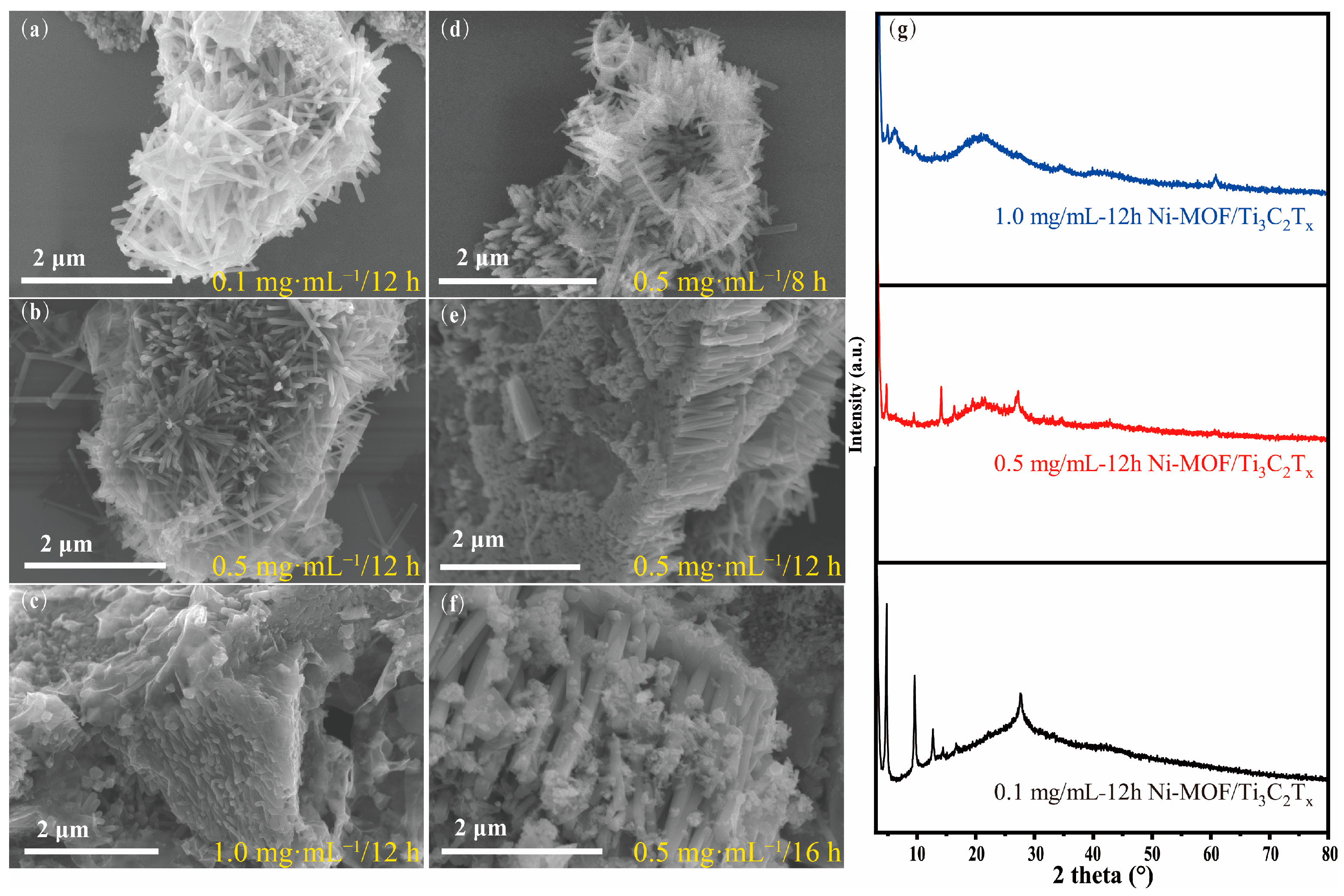
3.2. Morphology Controlled by Concentration and Reaction Time

The concentration of Ti3C2Tx and the reaction time have a direct effect on the micromorphology and structure of the Ni-MOF/Ti3C2Tx products, which makes an important impact on the electrochemical performance. On the one hand, the concentration of the Ti3C2Tx solution determines whether the forest-like Ni-MOF array vertically grows on the surface of Ti3C2Tx successfully. When the concentration of the solution is 0.1 mg∙mL−1, a small quantity of Ti3C2Tx is entirely covered by the relatively excessive Ni-MOF nanorods in no particular order (Figure 3a), resulting in the intensity of the corresponding (002) peaks of Ti3C2Tx disappearing in its XRD patten as shown in the black line of Figure 3g. When the solution increases to 1.0 mg∙mL−1, compared with the morphology of the sample obtained at 0.5 mg∙mL−1 (Figure 3c), Ni-MOF displays a nanosheet structure with a low density of distribution on the surface of Ti3C2Tx. As a result, the XRD pattern shows the characteristic peaks of Ti3C2Tx and Ni-MOF at 6.1° and 4.8°, respectively, indicating that Ni-MOF adhered to the surface prevents Ti3C2Tx from accumulating and increases the lattice space of the Ti3C2Tx nanosheets (blue line in Figure 2g). In addition, the intensity of Ti3C2Tx’s and Ni-MOF’s characteristic peaks all show strong signals because the low density of Ni-MOF cannot cover the surface and leads to exposure of the (002) face of the Ti3C2Tx rather than disappearance or weakness of the intensity as for the above two samples. On the other hand, the reaction time decides the size of the final Ni-MOF products. It can be clearly found that the length of Ni-MOF increases from ~250 nm of 8 h, ~550 nm of 12 h, to ~2.5 μm of 18 h by comparing the results of Figure 3d–f. To summarize, the concentration of Ti3C2Tx and the reaction time play pivotal roles in controlling the architecture of the Ni-MOF/Ti3C2Tx nanocomposite, which is due to providing different growth environments for Ni-MOF. A low Ti3C2Tx concentration and a limited reaction time provide insufficient growth conditions for Ni-MOF anchoring on the surface of Ti3C2Tx. By contrast, when up to 1.0 mg∙mL−1, the quantity of the Ni ions and the HHTP ligand cannot satisfy continuous growth after anchoring. Under 0.5 mg∙mL−1 and for 12 h, the Ni-MOF nanorods can grow uniformly on the surface of the Ti3C2Tx nanosheets. The different morphologies significantly impact the electrochemical performance of the products.

3.3. Electrochemical Properties

The cyclic voltammetry (CV) and galvanostatic charge–discharge (GCD) tests were performed to measure the electrochemical capacitance via the traditional three-electrode system using 6 M KOH as the electrolyte and Hg/HgO as the reference electrode. The redox peak can be clearly seen from the CV curves rather than rectangular shapes, which demonstrates the typical pseudocapacitive behavior (Figure 4a). As shown in Figure 4c, the GCD curves clearly show that the specific capacitance of the Ni-MOF/Ti3C2Tx nanocomposite can reach as high as 497.6 F·g−1 (0.5 A·g−1), which can remain over 66% of the initial capacitance when the current density increases five times from 0.5 to 2.5 A·g−1. Additionally, it shows a long discharge plateau period, which has great potential in practical applications. The good electrochemical performance of the Ni-MOF-Ti3C2Tx nanocomposite can be attributed to the synergetic combination of the excellent conductivity of the Ti3C2Tx substrate and the abundant redox active sites of MOF for electron transfer and ion transport. Because of the strong interaction formed during in situ growth, the Ni-MOF/Ti3C2Tx nanocomposite can maintain over 85% of the initial capacitance after 1000 cycles (Figure 4e). The large capacitance mainly displays a pseudocapacitance behavior due to the abundant active metal sites on the surface of the 2D Ti3C2Tx nanosheets, the porous skeleton (electric double layer capacitor), and the benzoquinone reaction that happened at the skeleton of the Ni-MOF, which can provide a good capacity for charge storage [45,46]. Additionally, the change of the impedance shows an obvious change (Figure S10), which might be caused by the less irreversible passivation behavior of the nanomaterials during the electrochemical cycles.
Furthermore, it can be explicitly proved that the architectures of the Ni-MOF/Ti3C2Tx samples prepared from different parameters have an important effect on the electrochemical capacities, as shown in the GCD curves of Figure 4c. When the concentration of the Ti3C2Tx solution is 0.1 and 1.0 mg∙mL−1, the capacitance is 76.5 and 172.5 F·g−1, respectively, because no order structure hinders ion transport and the failure of the forest-like Ni-MOF nanorods cannot provide sufficient active sites and pathways. In addition, the Ni-MOF/Ti3C2Tx samples prepared by 8 h and 16 h have much lower electrochemical capacitances of 268.8 F·g−1 and 200.0 F·g−1 at 0.5 A·g−1, respectively. It can be deduced that there is a trade-off effect between the number of redox active sites and the length of the ion pathways. When the growth time is short (8 h) or the Ti3C2Tx substrate is insufficient (0.1 mg∙mL−1), there are not abundant sites for an electrochemical reaction. Pathways that are too long are formed from the Ni-MOF nanorods (16 h, 1.0 mg∙mL−1) and can also impede the available movement of ions, resulting in an optimal Ni-MOF/Ti3C2Tx sample obtained from a growth time of 12 h and a Ti3C2Tx solution of 0.5 mg∙mL−1 with larger capacitance and capacitance retention, as revealed in Figure 4d. Additionally, the comparison of the rate capacitance and the energy density, as shown in Figure 4d, Figures S7 and S8, exhibits the Ni-MOF/Ti3C2Tx nanocomposite possesses an excellent energy density of 223.9 KWh·kg−1 at a power density of 1953.3 W·kg−1 (Figure S9), which surpasses the purely conducive MOF and Ti3C2Tx and some of the MOF-Ti3C2Tx composites.
Lastly, as depicted in Figure 5a, an all-solid-state asymmetric flexible supercapacitor was assembled by employing a Ni-MOF/Ti3C2Tx nanocomposite as the cathode and activated carbon as the anode. Additionally, the voltage window was fixed to 1.5 V by the cycle voltammetry test on the anode and cathode, respectively (Figure S11). The flexible device exhibits a specific capacitance of 128 F·g−1, calculated through CV tests, and the devices have succeeded in lighting a LED as shown in Figure 5b. The GCD test of the device shows a good charge and discharge curve as depicted in Figure 5c. Additionally, the EIS test (Figure 5d) shows the small impedance of the flexible supercapacitor, which can reduce the energy loss effectively. Moreover, the device shows good electrochemical stability of more than 90 GCD cycles, as shown in Figure 5e. Additionally, it can be observed from Figure S12, with the bending angle change from 0° to 30° and 60°, the CV curves show an inconspicuous change, which also demonstrates their good stability when applied to the bending scenario.

4. Conclusions

In summary, we have developed a novel Ni-MOF/Ti3C2Tx electrode material with a high order nanorods forest in situ grown on 2D Ti3C2Tx nanosheets. By controlling the Ti3C2Tx concentration and the hydrothermal reaction time, the relationship between the microstructure and electrochemical performance is successfully revealed. Benefiting from Ni-MOF’s abundant active redox sites and Ti3C2Tx’s high conductivity, the in situ combination identifies an electrochemical performance of 497.6 F·g−1 (0.5 A·g−1) and a capacitive retention of over 66% of the initial capacity when the current density is increased five times, which can be attributed to the synergistic effect of Ni-MOF and Ti3C2Tx. The “Ti-O···Ni” bond formed during in situ growth offers a strong interfacial combination between Ni-MOF and Ti3C2Tx. Ni-MOF provides sufficient active sites, effective ion transportation pathways, and avoids stacking of Ti3C2Tx, while Ti3C2Tx acts as a high conductivity material. The device shows good performance and stability in tests, which shows its potential in practical applications. Thus, this work provides a new material for electrochemical applications.

Supplementary Materials

The following supporting information can be downloaded at: https://www.mdpi.com/article/10.3390/nano13030610/s1, Figure S1. The SEM image of the Ti3C2Tx nanosheets, Figure S2. The XRD pattern of the Ti3C2Tx, Figure S3. FT-IR pattern of (a) Ti3C2Tx and (b) Ni-MOF, respectively, Figure S4. The pore size distribution of Ni-MOF/Ti3C2Tx, Figure S5. XPS spectra of Ni-MOF/Ti3C2Tx, Figure S6. High-resolution O 1s spectra of Ti3C2Tx, Ni-MOF, Ni-MOF/Ti3C2Tx, respectively, Figure S7. Comparation of rate capacitance of Ni-MOF/Ti3C2Tx, with different growth conditions, Figure S8. Comparation of energy density of Ni-MOF/Ti3C2Tx, with different growth conditions, Figure S9. Energy density at different Power density of Ni-MOF/Ti3C2Tx, Figure S10. The EIS test of the Ni-MOF/Ti3C2Tx before and after stability test, Figure S11. Energy density at different Power density of Ni-MOF/Ti3C2Tx, Figure S12. The CV test under original or bending states.

Author Contributions

Conceptualization, S.L. and Y.W.; methodology, S.L., T.L. and T.Z.; software, S.L. and Y.W.; validation, S.L., Y.W. and Y.L.; formal analysis, Y.L. and T.L.; investigation, J.X., T.L. and T.Z.; resources, T.L. and T.Z.; data curation, S.L.; writing—original draft preparation, S.L.; writing—review and editing, S.L., T.L. and T.Z.; supervision, J.X., T.L. and T.Z.; project administration, J.X., T.L. and T.Z.; funding acquisition, T.L. and T.Z. All authors have read and agreed to the published version of the manuscript.

Funding

This research was funded by the National Key R & D Program of China (2020YFB2008501), the National Science Fund for Distinguished Young Scholars of China (62125112), the National Natural Science Foundation of China (62071462, 62071463), the Jiangxi Provincial Natural Science Foundation (20224ACB212001), the Youth Promotion Association of Chinese Academy of Sciences (2020320), the Foundation Research Project of Jiangsu Province (BK20201195), and the Suzhou Key Industrial Technology Innovation Project (SYG202029). The authors are grateful for the technical support from Nano-X Vacuum Interconnected Workstation of Suzhou Institute of Nano-Tech and Nano-Bionics, Chinese Academy of Sciences (SINANO).

Data Availability Statement

The data presented in this study are available within the article.

Conflicts of Interest

The authors declare no conflict of interest.

References

  1. Wang, J.; He, N.; Fei, J.; Ma, Z.; Ji, Z.; Chen, Z.; Nie, N.; Huang, Y. Flexible and wearable fuel cells: A review of configurations and applications. J. Power Sources 2022, 551, 232190. [Google Scholar] [CrossRef]
  2. Zhao, J.; Zha, J.; Zeng, Z.; Tan, C. Recent advances in wearable self-powered energy systems based on flexible energy storage devices integrated with flexible solar cells. J. Mater. Chem. A 2021, 9, 18887–18905. [Google Scholar] [CrossRef]
  3. Dubal, D.P.; Chodankar, N.R.; Kim, D.-H.; Gomez-Romero, P. Towards flexible solid-state supercapacitors for smart and wearable electronics. Chem. Soc. Rev. 2018, 47, 2065–2129. [Google Scholar] [CrossRef] [PubMed]
  4. Swain, N.; Tripathy, A.; Thirumurugan, A.; Saravanakumar, B.; Schmidt-Mende, L.; Ramadoss, A. A brief review on stretchable, compressible, and deformable supercapacitor for smart devices. Chem. Eng. J. 2022, 446, 136876. [Google Scholar] [CrossRef]
  5. Keum, K.; Kim, J.W.; Hong, S.Y.; Son, J.G.; Lee, S.S.; Ha, J.S. Flexible/Stretchable Supercapacitors with Novel Functionality for Wearable Electronics. Adv. Mater. 2020, 32, 2002180. [Google Scholar] [CrossRef]
  6. Islam, M.R.; Afroj, S.; Novoselov, K.S.; Karim, N. Smart Electronic Textile-Based Wearable Supercapacitors. Adv. Sci. 2022, 9, 2203856. [Google Scholar] [CrossRef]
  7. Xie, P.; Yuan, W.; Liu, X.; Peng, Y.; Yin, Y.; Li, Y.; Wu, Z. Advanced carbon nanomaterials for state-of-the-art flexible supercapacitors. Energy Storage Mater. 2021, 36, 56–76. [Google Scholar] [CrossRef]
  8. Zhao, W.; Jiang, M.; Wang, W.; Liu, S.; Huang, W.; Zhao, Q. Flexible Transparent Supercapacitors: Materials and Devices. Adv. Funct. Mater. 2021, 31, 2009136. [Google Scholar] [CrossRef]
  9. Delbari, S.A.; Ghadimi, L.S.; Hadi, R.; Farhoudian, S.; Nedaei, M.; Babapoor, A.; Namini, A.S.; Quyet Van, L.; Shokouhimehr, M.; Asl, M.S.; et al. Transition metal oxide-based electrode materials for flexible supercapacitors: A review. J. Alloys Compd. 2021, 857, 158281. [Google Scholar] [CrossRef]
  10. Furukawa, H.; Cordova, K.E.; O’Keeffe, M.; Yaghi, O.M. The Chemistry and Applications of Metal-Organic Frameworks. Science 2013, 341, 1230444. [Google Scholar] [CrossRef] [Green Version]
  11. Liu, W.X.; Yin, R.L.; Xu, X.L.; Zhang, L.; Shi, W.H.; Cao, X.H. Structural Engineering of Low-Dimensional Metal-Organic Frameworks: Synthesis, Properties, and Applications. Adv. Sci. 2019, 6, 1802373. [Google Scholar] [CrossRef] [PubMed]
  12. Chakraborty, G.; Park, I.H.; Medishetty, R.; Vittal, J.J. Two-Dimensional Metal-Organic Framework Materials: Synthesis, Structures, Properties and Applications. Chem. Rev. 2021, 121, 3751–3891. [Google Scholar] [CrossRef] [PubMed]
  13. Sun, J.F.; Guo, L.Z.; Sun, X.; Zhang, J.Y.; Liu, Y.; Hou, L.R.; Yuan, C.Z. Conductive Co-based metal-organic framework nanowires: A competitive high-rate anode towards advanced Li-ion capacitors. J. Mater. Chem. A 2019, 7, 24788–24791. [Google Scholar] [CrossRef]
  14. Duan, H.Y.; Zhao, Z.M.; Lu, J.D.; Hu, W.H.; Zhang, Y.; Li, S.S.; Zhang, M.F.; Zhu, R.M.; Pang, H. When Conductive MOFs Meet MnO2: High Electrochemical Energy Storage Performance in an Aqueous Asymmetric Supercapacitor. ACS Appl. Mater. Interfaces 2021, 13, 33083–33090. [Google Scholar] [CrossRef] [PubMed]
  15. Cherusseri, J.; Pandey, D.; Kumar, K.S.; Thomas, J.; Zhai, L. Flexible supercapacitor electrodes using metal-organic frameworks. Nanoscale 2020, 12, 17649–17662. [Google Scholar] [CrossRef]
  16. Dedek, I.; Kupka, V.; Jakubec, P.; Sedajova, V.; Jayaramulu, K.; Otyepka, M. Metal-organic framework/conductive polymer hybrid materials for supercapacitors. Appl. Mater. Today 2022, 26, 101387. [Google Scholar] [CrossRef]
  17. Sheberla, D.; Bachman, J.C.; Elias, J.S.; Sun, C.J.; Shao-Horn, Y.; Dinca, M. Conductive MOF electrodes for stable supercapacitors with high areal capacitance. Nat. Mater. 2017, 16, 220–224. [Google Scholar] [CrossRef]
  18. Hou, R.Z.; Miao, M.; Wang, Q.Y.; Yue, T.; Liu, H.F.; Park, H.S.; Qi, K.; Xia, B.Y. Integrated Conductive Hybrid Architecture of Metal-Organic Framework Nanowire Array on Polypyrrole Membrane for All-Solid-State Flexible Supercapacitors. Adv. Energy Mater. 2020, 10, 1901892. [Google Scholar] [CrossRef]
  19. Ninawe, P.; Gupta, K.; Ballav, N. Chemically Integrating a 2D Metal-Organic Framework with 2D Functionalized Graphene. Inorg. Chem. 2021, 60, 19079–19085. [Google Scholar] [CrossRef]
  20. Ran, F.T.; Xu, X.Q.; Pan, D.; Liu, Y.Y.; Bai, Y.P.; Shao, L. Ultrathin 2D Metal-Organic Framework Nanosheets In situ Interpenetrated by Functional CNTs for Hybrid Energy Storage Device. Nano-Micro Lett. 2020, 12, 46. [Google Scholar] [CrossRef] [Green Version]
  21. Song, Y.D.; Ho, W.H.; Chen, Y.C.; Li, J.H.; Wang, Y.S.; Gu, Y.J.; Chuang, C.H.; Kung, C.W. Selective Formation of Polyaniline Confined in the Nanopores of a Metal-Organic Framework for Supercapacitors. Chem. A Eur. J. 2021, 27, 3560–3567. [Google Scholar] [CrossRef] [PubMed]
  22. Gautam, K.P.; Acharya, D.; Bhatta, I.; Subedi, V.; Das, M.; Neupane, S.; Kunwar, J.; Chhetri, K.; Yadav, A.P. Nickel Oxide-Incorporated Polyaniline Nanocomposites as an Efficient Electrode Material for Supercapacitor Application. Inorganics 2022, 10, 86. [Google Scholar] [CrossRef]
  23. Acharya, D.; Pathak, I.; Dahal, B.; Lohani, P.C.; Bhattarai, R.M.; Muthurasu, A.; Kim, T.; Ko, T.H.; Chhetri, K.; Kim, H.Y. Immoderate nanoarchitectures of bimetallic MOF derived Ni-Fe-O/NPC on porous carbon nanofibers as freestanding electrode for asymmetric supercapacitors. Carbon 2023, 201, 12–23. [Google Scholar] [CrossRef]
  24. Mohammadi, A.V.; Rosen, J.; Gogotsi, Y. The world of two-dimensional carbides and nitrides (MXenes). Science 2021, 372, eabf1581. [Google Scholar]
  25. Li, X.L.; Huang, Z.D.; Shuck, C.E.; Liang, G.J.; Gogotsi, Y.; Zhi, C.Y. MXene chemistry, electrochemistry and energy storage applications. Nat. Rev. Chem. 2022, 6, 389–404. [Google Scholar] [CrossRef]
  26. Zhang, J.Z.; Kong, N.; Uzun, S.; Levitt, A.; Seyedin, S.; Lynch, P.A.; Qin, S.; Han, M.K.; Yang, W.R.; Liu, J.Q.; et al. Scalable Manufacturing of Free-Standing, Strong Ti3C2Tx MXene Films with Outstanding Conductivity. Adv. Mater. 2020, 32, 2001093. [Google Scholar] [CrossRef]
  27. Ghidiu, M.; Lukatskaya, M.R.; Zhao, M.Q.; Gogotsi, Y.; Barsoum, M.W. Conductive two-dimensional titanium carbide ‘clay’ with high volumetric capacitance. Nature 2014, 516, 78–81. [Google Scholar] [CrossRef]
  28. Luo, Y.J.; Que, W.X.; Bin, X.Q.; Xia, C.J.; Kong, B.S.; Gao, B.W.; Kong, L.B. Flexible MXene-Based Composite Films: Synthesis, Modification, and Applications as Electrodes of Supercapacitors. Small 2022, 18, 2201290. [Google Scholar] [CrossRef]
  29. Yu, H.; Wang, Y.H.; Jing, Y.; Ma, J.M.; Du, C.F.; Yan, Q.Y. Surface Modified MXene-Based Nanocomposites for Electrochemical Energy Conversion and Storage. Small 2019, 15, 1901503. [Google Scholar] [CrossRef]
  30. Luo, J.M.; Matios, E.; Wang, H.; Tao, X.Y.; Li, W.Y. Interfacial structure design of MXene-basednanomaterials for electrochemical energy storage and conversion. InfoMat 2020, 2, 1057–1076. [Google Scholar] [CrossRef]
  31. Fu, Z.H.; Wang, N.; Legut, D.; Si, C.; Zhang, Q.F.; Du, S.Y.; Germann, T.C.; Francisco, J.S.; Zhang, R.F. Rational Design of Flexible Two-Dimensional MXenes with Multiple Functionalities. Chem. Rev. 2019, 119, 11980–12031. [Google Scholar] [CrossRef] [PubMed]
  32. Wen, D.; Ying, G.B.; Liu, L.; Li, Y.X.; Sun, C.; Hu, C.; Zhao, Y.L.; Ji, Z.Y.; Zhang, J.F.; Wang, X. Direct inkjet printing of flexible MXene/graphene composite films for supercapacitor electrodes. J. Alloys Compd. 2022, 900, 163436. [Google Scholar] [CrossRef]
  33. Wen, D.; Wang, X.; Liu, L.; Hu, C.; Sun, C.; Wu, Y.R.; Zhao, Y.L.; Zhang, J.X.; Liu, X.D.; Ying, G.B. Inkjet Printing Transparent and Conductive MXene (Ti3C2Tx) Films: A Strategy for Flexible Energy Storage Devices. ACS Appl. Mater. Interfaces 2021, 13, 17766–17780. [Google Scholar] [CrossRef] [PubMed]
  34. Zhao, Z.F.; Wang, S.; Wan, F.; Tie, Z.W.; Niu, Z.Q. Scalable 3D Self-Assembly of MXene Films for Flexible Sandwich and Microsized Supercapacitors. Adv. Funct. Mater. 2021, 31, 2101302. [Google Scholar] [CrossRef]
  35. Jimmy, J.; Kandasubramanian, B. Mxene functionalized polymer composites: Synthesis and applications. Eur. Polym. J. 2020, 122, 109367. [Google Scholar] [CrossRef]
  36. Liu, Y.Y.; Yu, J.X.; Guo, D.F.; Li, Z.J.; Su, Y.J. Ti3C2Tx MXene/graphene nanocomposites: Synthesis and application in electrochemical energy storage. J. Alloys Compd. 2020, 815, 152403. [Google Scholar] [CrossRef]
  37. Saini, H.; Srinivasan, N.; Sedajova, V.; Majumder, M.; Dubal, D.P.; Otyepka, M.; Zboril, R.; Kurra, N.; Fischer, R.A.; Jayaramulu, K. Emerging MXene@Metal-Organic Framework Hybrids: Design Strategies toward Versatile Applications. ACS Nano 2021, 15, 18742–18776. [Google Scholar] [CrossRef]
  38. Liu, C.L.; Bai, Y.; Li, W.T.; Yang, F.Y.; Zhang, G.X.; Pang, H. In Situ Growth of Three-Dimensional MXene/Metal-Organic Framework Composites for High-Performance Supercapacitors. Angew. Chem. Int. Ed. 2022, 61, 18742–18776. [Google Scholar]
  39. Yang, X.F.; Tian, Y.H.; Li, S.; Wu, Y.P.; Zhang, Q.C.; Li, D.S.; Zhang, S.Q. Heterogeneous Ni-MOF/V2CTx-MXene hierarchically-porous nanorods for robust and high energy density hybrid supercapacitors. J. Mater. Chem. A 2022, 10, 12225–12234. [Google Scholar] [CrossRef]
  40. Alhabeb, M.; Maleski, K.; Anasori, B.; Lelyukh, P.; Clark, L.; Sin, S.; Gogotsi, Y. Guidelines for Synthesis and Processing of Two-Dimensional Titanium Carbide (Ti3C2TX MXene). Chem. Mater. 2017, 29, 7633–7644. [Google Scholar] [CrossRef]
  41. Shi, Y.X.; Wu, Y.; Wang, S.Q.; Zhao, Y.Y.; Li, T.; Yang, X.Q.; Zhang, T. Soft Electrochemical Actuators with a Two-Dimensional Conductive Metal-Organic Framework Nanowire Array. J. Am. Chem. Soc. 2021, 143, 4017–4023. [Google Scholar] [CrossRef] [PubMed]
  42. Zheng, S.S.; Zhou, H.J.; Xue, H.G.; Braunstein, P.; Pang, H. Pillared-layer Ni-MOF nanosheets anchored on Ti3C2 MXene for enhanced electrochemical energy storage. J. Colloid Interface Sci. 2022, 614, 130–137. [Google Scholar] [CrossRef] [PubMed]
  43. Peng, C.; Yang, X.F.; Li, Y.H.; Yu, H.; Wang, H.J.; Peng, F. Hybrids of Two-Dimensional Ti3C2 and TiO2 Exposing {001} Facets toward Enhanced Photocatalytic Activity. ACS Appl. Mater. Interfaces 2016, 8, 6051–6060. [Google Scholar] [CrossRef] [PubMed]
  44. Natu, V.; Benchakar, M.; Canaff, C.; Habrioux, A.; Celerier, S.; Barsoum, M.W. A critical analysis of the X-ray photoelectron spectra of Ti3C2Tz MXenes. Matter 2021, 4, 1224–1251. [Google Scholar] [CrossRef]
  45. Lukatskaya, M.R.; Kota, S.; Lin, Z.F.; Zhao, M.Q.; Shpigel, N.; Levi, M.D.; Halim, J.; Taberna, P.L.; Barsoum, M.; Simon, P.; et al. Ultra-high-rate pseudocapacitive energy storage in two-dimensional transition metal carbides. Nat. Energy 2017, 2, 17105. [Google Scholar] [CrossRef]
  46. Herebian, D.; Bothe, E.; Neese, F.; Weyhermuller, T.; Wieghardt, K. Molecular and electronic structures of bis-(o-diiminobenzosemiquinonato)metal(II) complexes (Ni, Pd, Pt), their monocations and -anions, and of dimeric dications containing weak metal-metal bonds. J. Am. Chem. Soc. 2003, 125, 9116–9128. [Google Scholar] [CrossRef] [PubMed]
  47. Kshetri, T.; Khumujam, D.D.; Singh, T.I.; Lee, Y.S.; Kim, N.H.; Lee, J.H. Co-MOF@MXene-carbon nanofiber-based freestanding electrodes for a flexible and wearable quasi-solid-state supercapacitor. Chem. Eng. J. 2022, 437, 135338. [Google Scholar] [CrossRef]
  48. Li, W.H.; Ding, K.; Tian, H.R.; Yao, M.S.; Nath, B.; Deng, W.H.; Wang, Y.B.; Xu, G. Conductive Metal-Organic Framework Nanowire Array Electrodes for High-Performance Solid-State Supercapacitors. Adv. Funct. Mater. 2017, 27, 1702067. [Google Scholar] [CrossRef]
  49. Li, T.F.; Yao, L.L.; Liu, Q.L.; Gu, J.J.; Luo, R.C.; Li, J.H.; Yan, X.D.; Wang, W.Q.; Liu, P.; Chen, B.; et al. Fluorine-Free Synthesis of High-Purity Ti3C2Tx (T=OH, O) via Alkali Treatment. Angew. Chem. Int. Ed. 2018, 57, 6115–6119. [Google Scholar] [CrossRef]
Figure 1. (a) Schematic illustration of the synthesis of Ni-MOF/Ti3C2Tx sample; (b) SEM image of Ni-MOF/Ti3C2Tx; (c) TEM image of Ni-MOF/Ti3C2Tx; (d) HRTEM image of Ni-MOF nanorods; and (e) EDS mapping of Ni-MOF/Ti3C2Tx.
Nanomaterials 13 00610 g001
Figure 2. (a) XRD pattern, (b) FT-IR spectrum, and (c) BET curve of the Ni-MOF/Ti3C2Tx sample; (d,e) XPS peaks of Ti and Ni elements in Ni-MOF/Ti3C2Tx, respectively; and (f) the illustration of Ti-O···Ni interaction between Ni-MOF and Ti3C2Tx.
Nanomaterials 13 00610 g002
Figure 3. (ac) SEM images of the Ni-MOF/Ti3C2Tx samples within the same 12 h reaction time at different Ti3C2Tx concentrations of 0.1 mg·mL−1, 0.5 mg·mL−1, and 1.0 mg·mL−1, respectively; (df) SEM images of the Ni-MOF/Ti3C2Tx products at the same concentration 0.5 mg·mL−1 of Ti3C2Tx within different reaction times of 8 h, 12 h, and 16 h, respectively; and (g) XRD pattern of the Ni-MOF/Ti3C2Tx samples grown at different Ti3C2Tx concentrations.
Nanomaterials 13 00610 g003
Figure 4. (a) CV curves of the Ni-MOF/Ti3C2Tx sample prepared by growth condition of 0.5 mg∙mL−1 and 12 h; (b) the corresponding determination of b-values based on cathodic and anodic peaks; (c) GCD curves of the Ni-MOF/Ti3C2Tx samples obtained by different growth conditions; (d) the comparation of rate capacitance between Ni-MOF/Ti3C2Tx products with different growth conditions; (e) cycling behaviors of the Ni-MOF/Ti3C2Tx sample of 0.5 mg∙mL−1 and 12 h growth conditions; and (f) ragone plots of the Ni-MOF/Ti3C2Tx sample compared with previous studies [17,38,47,48,49].
Nanomaterials 13 00610 g004
Figure 5. (a) Schematic illustration of flexible supercapacitor and the CV electrochemical test of the device; (b) success in lighting a LED; (c) the GCD curves of the device; (d) the EIS curves of the device; and (e) the cycle test of the device.
Nanomaterials 13 00610 g005
Disclaimer/Publisher’s Note: The statements, opinions and data contained in all publications are solely those of the individual author(s) and contributor(s) and not of MDPI and/or the editor(s). MDPI and/or the editor(s) disclaim responsibility for any injury to people or property resulting from any ideas, methods, instructions or products referred to in the content.

