Article

Effects of Top and Bottom Electrodes Materials and Operating Ambiance on the Characteristics of MgFx Based Bipolar RRAMs

1
Department of Energy Engineering, Korea Institute of Energy Technology, Naju 58330, Republic of Korea
2
School of Electrical Engineering and Computer Science, Gwangju Institute of Science and Technology, Gwangju 61005, Republic of Korea
*
Author to whom correspondence should be addressed.
Nanomaterials 2023, 13(6), 1127; https://doi.org/10.3390/nano13061127
Submission received: 21 February 2023 / Revised: 16 March 2023 / Accepted: 20 March 2023 / Published: 22 March 2023
(This article belongs to the Special Issue Intelligent Nanomaterials and Nanosystems)

Abstract

:
The effects of electrode materials (top and bottom) and the operating ambiances (open-air and vacuum) on the MgFx-based resistive random-access memory (RRAM) devices are studied. Experiment results show that the device’s performance and stability depend on the difference between the top and bottom electrodes’ work functions. Devices are robust in both environments if the work function difference between the bottom and top electrodes is greater than or equal to 0.70 eV. The operating environment-independent device performance depends on the surface roughness of the bottom electrode materials. Reducing the bottom electrodes’ surface roughness will reduce moisture absorption, minimizing the impact of the operating environment. Ti/MgFx/p+-Si memory devices with the minimum surface roughness of the p+-Si bottom electrode show operating environment-independent electroforming-free stable resistive switching properties. The stable memory devices show promising data retentions of >104 s in both environments with DC endurance properties of more than 100 cycles.

1. Introduction

Among the potential non-volatile memory (NVM) technologies, resistive random-access memory (RRAM) is a promising candidate for embedded memory and storage class memory applications due to its excellent scalability, prolonged durability, simple architecture, and compatibility with CMOS technology [1,2,3]. RRAM also has the potential for neuromorphic applications because of its ability to mimic biological synapses [3,4]. Numerous material systems with various switching processes are being studied. Several efforts have been made to design conductive channels to build uniform and controlled conductive filaments in resistive switching devices [1]. However, unstable switching characteristics, including large fluctuations of Set/Reset voltages, are big obstacles to the practical application of RRAM [1,5,6].
Numerous models have been developed to improve RRAM’s uniform switching behaviors, such as structure optimization, metal ion transplanting, adding a metal interface layer, metal doping, electrode optimization, and interface engineering [1,2,3]. RRAM devices with varied electrode materials and the same oxide layer have been reported to exhibit different electrical properties [3,7,8]. The electrodes in RRAM devices significantly impact how resistive switching (RS) behaves. Due to the variations in the work functions of various electrodes and the type of contact between an electrode and an active layer, electrode materials influence distinct RS behaviors by changing the barrier height at the electrode/active layer interface [6,7,9,10,11,12].
Materials selection requires understanding the material characteristics influencing each device’s performance factors, such as on/off ratio, switching speed, retention time, and durability. It is also essential to understand how the operating environment affects the performance of the RRAM device to develop and control its properties [13]. The electrode metals and operating conditions affect the vacancy formation energy [14]. In oxygen-rich environments, the heat of formation for each oxygen atom in the bulk oxide tends to be equivalent to the vacancy formation energy. In contrast, it tends to be near zero in oxygen-poor environments [14]. Additionally, when the device size reduces, the impacts of gaseous ambiance become more pronounced due to the larger specific surface area. Moreover, surface roughness affects a device’s performance in the open air and under a vacuum because it increases moisture absorption [10,15,16,17].
Binary oxide-based materials have recently undergone in-depth research in a vacuum as an active layer of RRAM devices [18,19,20,21,22]. Due to the abundance of oxygen in the atmosphere, the performance of the memory devices and the oxygen vacancy-based active layer are greatly influenced by the working environment. According to studies, most binary oxide-based devices cannot be electroformed and are unstable in a vacuum [18,19,20,21,22]. In a vacuum, one way to overcome the limitations of oxygen vacancy-based RRAMs is to investigate alternate anion vacancy-based materials, which are less affected by the working environment.
Our latest work demonstrates the fluoride vacancy-based bipolar RS characteristics of Ti/MgFx/Pt devices in an open-air environment and a vacuum [23,24,25]. However, no research has yet been conducted on the effects of electrode materials (top and bottom) and operating environments (open-air and vacuum) on the performance of the fluoride vacancy-based device.
In this study, we have investigated the effects of electrode materials (top: Ti, Pt, Au/Ni, ITO, and bottom: Pt, p+-Si, n+-Si, ITO) on MgFx-based RRAM devices. We have also analyzed the effect of the operating environments. The effects of electrode material variations and operating ambiance on device performances can be determined by combining two factors: (1) the work function difference between the bottom and top electrodes (Δϕ) and (2) the surface roughness of the bottom electrodes. All the MgFx-based RRAM devices exhibit bipolar RS characteristics in an open-air and a vacuum environment. However, devices with Δϕ higher or equal to 0.70 eV are stable in both environments. The effect of the operating environment can be minimized by reducing the surface roughness of the bottom electrodes, which reduces moisture absorption. We have demonstrated operating environment-independent electroforming-free stable Ti/MgFx/p+-Si memory devices for the first time. Devices maintain similar electroforming-free bipolar RS characteristics in the open air and in a vacuum. Memory devices show promising retention and endurance properties.

2. Materials and Methods

E-beam evaporation was used to deposit a 150-nm-thick Pt bottom electrode on SiO2/Si substrate to fabricate Ti/MgFx/Pt devices. A circular shadow mask with a radius of 50 μm was used to design the different top electrodes (TE) (Ti = 150 nm, Pt = 150 nm, Au/Ni = 100/40 nm, ITO = 150 nm). As a bottom electrode (BE) variation, Pt was replaced by p+-Si, n+-Si, and ITO-coated glass.
The electrical characteristics of the memory devices were measured using a semiconductor parameter analyzer (HP-4155A) in a laboratory atmospheric ambiance. The top electrode received direct voltage, while the bottom electrode was grounded. The electrical characteristics of RRAM devices in a vacuum environment were measured using the MS-TECH Vacuum Chamber Probe Station (10−3 torr).
At least three batches of samples for each device type were analyzed to ensure reproducibility. A batch consists of more than twenty devices. More than fifty devices were measured at each condition to confirm the observations and conclusions. Because few process variables were involved in device fabrication and each process condition was well controlled, the range of device-to-device variation was smaller than the range of cycle-to-cycle variation.

3. Results and Discussion

In the previous works, the characterization of the MgFx thin films and the performance of Ti/MgFx/Pt devices were explored in a laboratory atmospheric ambiance and a vacuum [23,24,25]. The XRD pattern, SEM image, XPS analysis, and FTIR absorbance spectroscopy measurement results for the MgFx thin film, shown in the Supplementary File in Figure S1, are used to thoroughly study the structural, elemental, and compositional properties of the MgFx thin film. A summary of the MgFx thin films characterization is given below.
With an Mg/F ratio of about 1:1.65, which indicates fluoride vacancies in the film, the amorphous defect-rich granular-structured MgFx layer was deposited [23,25]. In open-air environemts, several weak hydroxyl groups and CO2 absorption peaks have been observed. These hydroxyl groups show that moisture was absorbed from the environment during the manufacturing or measuring processes and was present on the surface of amorphous MgFx. The hydroxyl groups weakly attached to the amorphous MgFx thin film surface are easily removed in a vacuum environment. These loosely connected groups affect the characteristics of the Ti/MgFx interface and the amorphous MgFx active layer. Consequently, the operating environment impacts the device’s performance [25].
Devices with six different electrode materials (Ti, Au/Ni, Pt, ITO, p+-Si, and n+-Si) were fabricated. The effects of top and bottom electrode materials and operating environment on the MgFx-based RRAM devices’ performance are systematically explored as follows:

3.1. Effect of Top Electrodes and Operating Environment

The RS characteristics of MgFx-based RRAM devices with TE (Ti, Pt, Au/Ni, or ITO) and BE (Pt) are measured in open-air and vacuum environments, as shown in Figure 1.
In an open-air environment, by applying a double voltage sweep in the sequence of 0 V → +3 V → 0 V → −3 V → 0 V with the compliance current (Icc) of 0.25 mA, electroforming free bipolar RS behavior of the Ti/MgFx/Pt devices was observed with an on/off ratio > 102.
In a vacuum environment, the RS features of a device must be activated using an electroforming process, where the initial resistance is higher than in an open-air environment (Figure 1a). In a vacuum, the following changes occur in device performance: (1) SET voltage drops from 1.25 V to 1.0 V, (2) RESET voltage changes from −0.9 V to −2.5 V, (3) SET and RESET current rise, and (4) on/off ratio falls from over 103 to 10 [23,25].
The Pt/MgFx/Pt devices show one-time RS from initial HRS to LRS and breakdown during negative bias voltage in the open-air environment and vacuum (Figure 1b). This phenomenon is attributed to the electroforming process, which forms irreversible conduction paths at the electrode–film interface [26].
The ITO/MgFx/Pt devices show interesting responses to the operating environment. In the open-air setting, devices do not show repetitive RS properties. However, RS properties are confirmed in a vacuum with high fluctuations (Figure 1c). SET voltage varies from 2.25 V to 6.5 V, and the RESET voltage varies from −0.5 V to −2.5 V, with different ranges of bias voltages.
The Au/Ni/MgFx/Pt devices show electroforming-free RS properties in the open-air environment and vacuum with 0 V → +2 V → 0 V → −1 V → 0 V bias voltage and an on/off ratio from over 102 with different compliance currents (Figure 1d). The SET voltage varies from 1.0 V to 1.5 V, and the RESET voltage varies from −0.5 V to −0.75 V. Devices show good potential to be free from operating environmental effects. However, devices are not stable. After around 20 cycles, devices break down.

3.2. Effect of Bottom Electrodes and Operating Environment

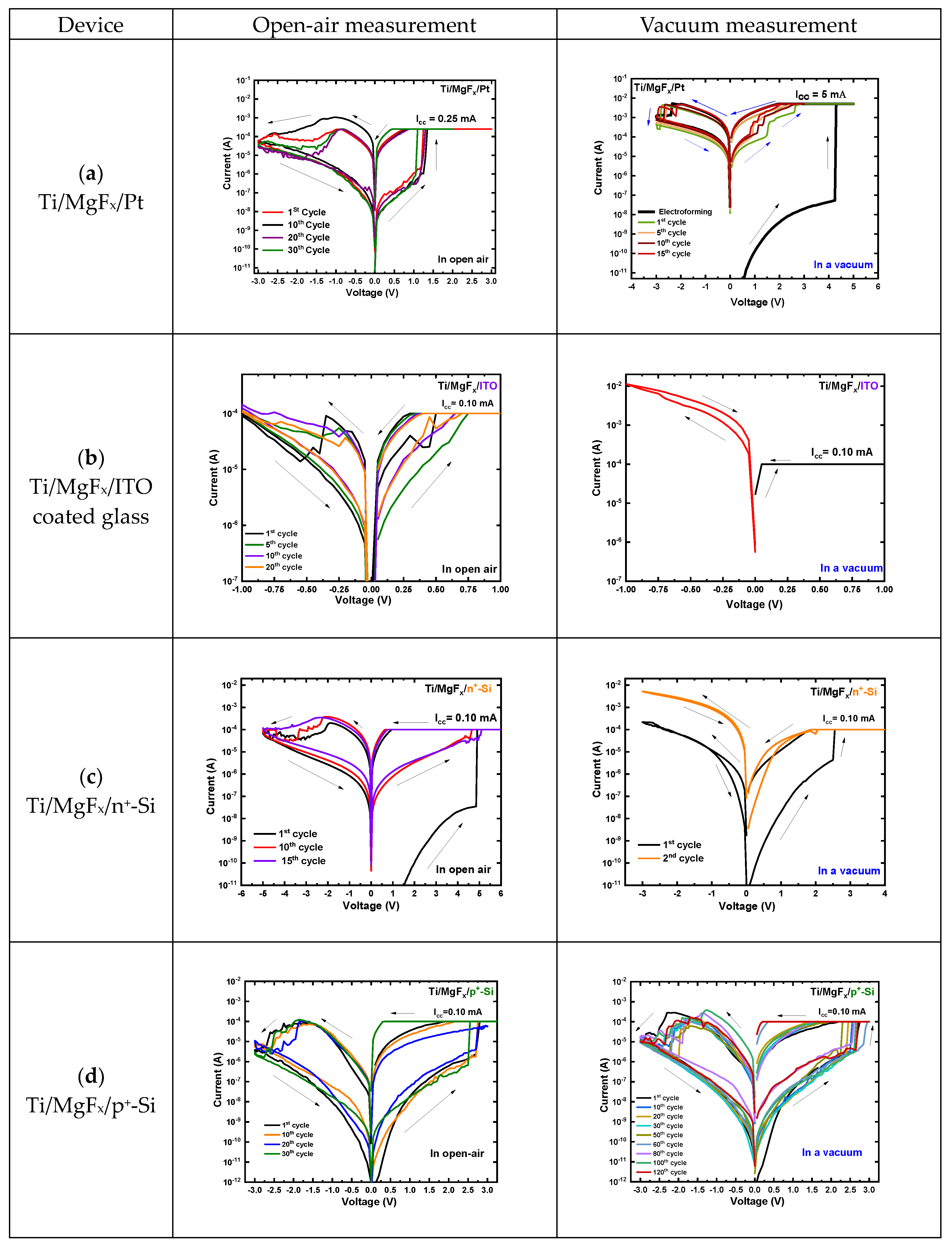
After variations of the TE materials in the Ti/MgFx/Pt device structure, the BE (Pt) is replaced by ITO-coated glass, n+-Si, or p+-Si substrates, keeping Ti as the top electrode. The I-V characteristics of MgFx-based RRAM with different bottom electrodes in the open-air environment and vacuum are shown in Figure 2.
Ti/MgFx/ITO devices also show electroforming-free RS characteristics in the open-air environment but fail to retain RS properties in the vacuum environment (Figure 2b). In an open-air environment, the SET voltage varies from 0.35 V to 0.75 V; the RESET voltage varies from −0.25 V to −0.50 V under the Icc of 0.10 mA, and the voltage sweep range is +1 V to −1 V. However, in a vacuum environment, the device becomes very conductive. This conductivity can be attributed to the O2− escape from the ITO bottom electrode. The formation of oxygen gas in a vacuum environment makes the device more conducive to oxygen vacancies [27].
Ti/MgFx/n+-Si devices exhibit uniform RS properties in the open air, with a voltage sweep range of +6 V to −5 V and an Icc of 0.10 mA. The SET voltage ranges from 4.5 V to 5.25 V, and the RESET voltage varies from −2.0 V to −2.50 V. However, devices do not show stable RS properties in a vacuum (Figure 2c).
Only Ti/MgFx/p+-Si devices are less affected by the changing operating environment and show stable electroforming-free RS properties both in open-air conditions and the vacuum. A readout voltage (VRead) was +0.50 V. In both open-air and vacuum environments, the SET voltage ranges from 2.25 V to 2.75 V, and the RESET voltage varies from −1.75 V to −2.25 V. With the voltage sweep range +3 V to −3 V, the on/off ratio is >102 in an open-air environment and a vacuum (Figure 2d).

3.3. Factors to Determine the Effect of Electrodes and Operating Environment

The effects of electrode materials variations and operating ambiance on device performances can be determined by combining two factors: (1) the work function difference between the bottom and top electrodes [9,10,11,12] and (2) the surface roughness of the bottom electrodes [10,15,16,17]. The work functions of the electrode materials are shown in Table 1, and the work function difference between the TE and BE of devices is shown in Table 2 [6,28].
The difference in work functions of BE and TE materials determines the electric field across the MgFx switching layer in a thermal equilibrium with no electrical bias [10]. From the device performance and the work function difference (Δϕ) between TE and BE, it is identified that the Δϕ should be higher or equal to 0.70 eV for stable MgFx-based RRAM devices in open-air and vacuum environments. When the Δϕ is smaller than 0.70 eV, RS properties are unstable and depend on the environment.
Figure 3 summarizes the device properties (VSET, VRESET, ILRS, and IHRS) with work function differences of TE and BE in open-air (Figure 3a,c) and vacuum environments (Figure 3b,d). The acronyms used to represent device properties properly in the graphs are NR (No RESET), NS (No SET), and NSP (No switching properties). A device is considered stable if it shows DC endurance properties over 100 cycles and more than 104 s of data retention. Any device that fails to meet the criteria is considered unstable.
The experimental results show that in any given environment (open-air and vacuum), out of the seven kinds of MgFx-based devices (Ti/MgFx/Pt, Pt/MgFx/Pt, ITO/MgFx/Pt, Au/Ni/MgFx/Pt, Ti/MgFx/ITO, Ti/MgFx/n+-Si, and Ti/MgFx/p+-Si), two types of devices (Ti/MgFx/Pt and Ti/MgFx/p+-Si) are very stable. Ti/MgFx/Pt memory devices’ stability (retention and endurance) in the open air and a vacuum environment are shown in previous works [23,24,25]. Ti/MgFx/p+-Si memory devices’ DC endurance properties are shown in Figure 2d, showing more than 120 cycles in a vacuum.
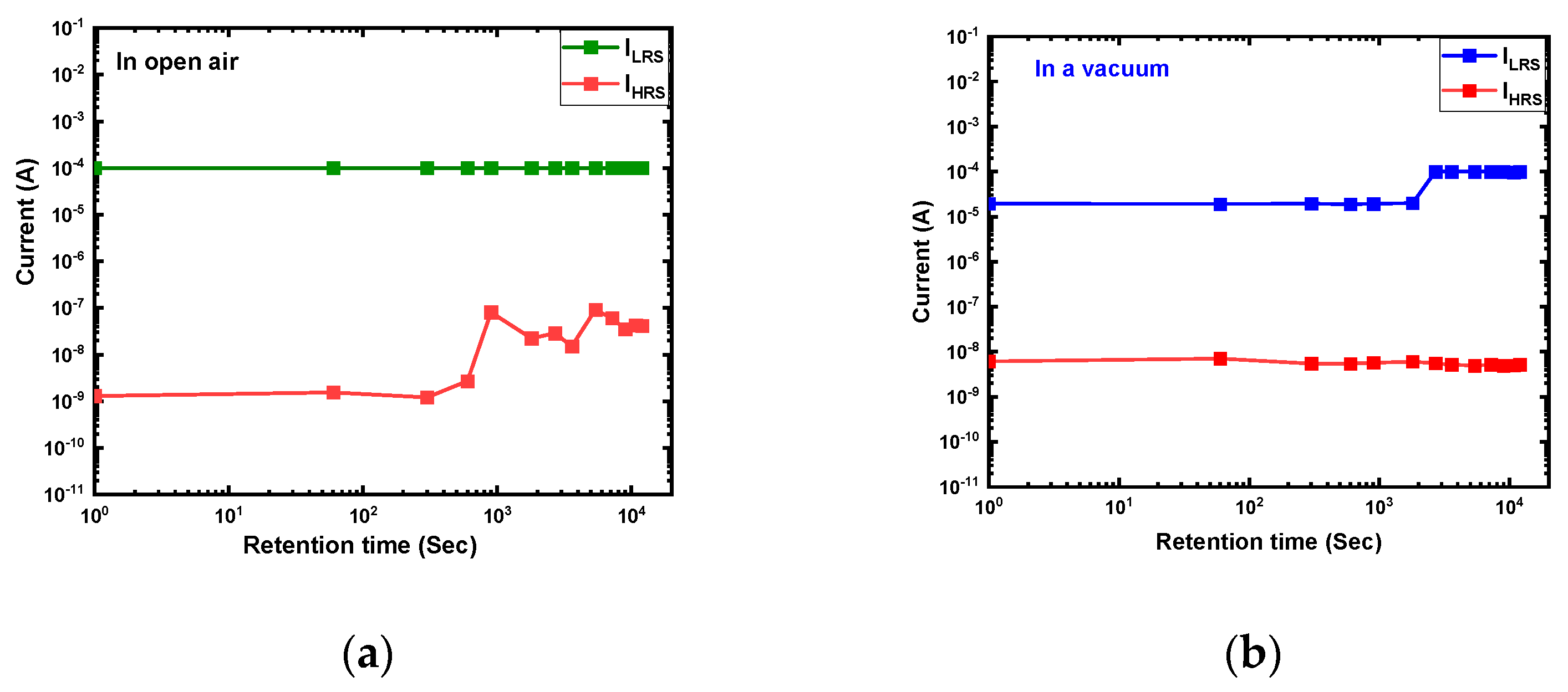
The data retention properties of the Ti/MgFx/p+-Si memory devices in the open air and a vacuum environment are shown in Figure 4. In both operating environments, the device exhibits good data retention over 104 s with an on/off ratio greater than 103. The LRS state is more stable and uniform in open-air measurements than the HRS. In a vacuum environment, both states are comparatively stable with time.
An e-beam deposited BE, and TE surface is significantly more uneven than a Si wafer surface as BE. The BE’s surface roughness significantly influences the device’s stability and the operational environment’s impact [10,15,16,17]. The MIM structure device’s rough surface can create more traps between the electrodes and the active layer at the interface. Furthermore, the degree of BE roughness significantly affects RS. The switching voltages are impacted by the local field-concentrating regions of the surface [10,15,16,17]. Additionally, surface roughness enhances moisture absorption, affecting the device’s performance in open-air and vacuum environments [17].
In an open-air environment, the pristine MgFx-based devices contain significant internal and external defects. The internal defects are fluoride vacancies in the bulk MgFx active layer, and the external defects are weakly bound to O-H groups on the surface of MgFx. These external defects enable the dissociation of O2− and H+ ions to generate anion vacancies at the interface. As a result, the ionic charge carriers in the interface region differ from those in bulk MgFx, increasing the conductivity of the interface region [22,29,30]. As a result, most of the MgFx-based devices show electroforming-free RS properties in an open-air environment.
However, weakly bound O-H groups and CO2 are eliminated from the interface region in a vacuum environment. Thus, only an electronic current is present, and the ionic charge carriers (O2− and H+) are gone. As a result, the active layer becomes more resistant, increasing the devices’ overall initial resistance, and an electroforming process is necessary to activate its RS capabilities [18,19,20,21,22,23,24,25,31].
The small Δϕ and surface roughness can explain the devices’ instability. The surface roughness values of substrates and BEs are presented in Table 3. It is easy to make a conduction filament between TE and the active layer without an electroforming process in an open-air environment because of the small Δϕ and existence of external defects (O-H groups) caused by the roughness of the BE and active layer surface [23,25]. As a result, most of the combinations of MgFx-based devices show electroforming-free RS properties. However, within a few cycles, a permanent conduction filament is formed between TE and the active layer, and the device loses RS properties. The fluctuation Ti/MgFx/ITO in a vacuum can be attributed to the ITO-coated glass’s highest surface roughness (SRRMS = 4.050 nm).
From the different top and bottom electrode combinations of MgFx-based devices, Ti/MgFx/Pt and Ti/MgFx/p+-Si are the most stable. However, the Ti/MgFx/p+-Si device is less affected by the operating environment and shows very stable electroforming-free RS performance in open-air and vacuum environments.
The surface morphology of the p+-Si, Pt BE, and after the MgFx layer deposition are shown in Figure 5. The p+-Si substrate (SRRMS = 0.250 nm) is much smoother than the e-beam deposited Pt BE (SRRMS = 1.701 nm). After MgFx deposition, the surface roughness of the MgFx on the p+-Si (SRRMS = 0.996 nm) is much less than that of the MgFx on the Pt (SRRMS = 2.008 nm). Thus, moisture absorption is lower at the interfaces of the Ti/MgFx/p+-Si device compared to the Ti/MgFx/Pt device. As a result, in an open-air environment, the initial resistance of Ti/MgFx/p+-Si (~GΩ) is higher than that of Ti/MgFx/Pt (~10 MΩ), even though p+-Si-based devices (0.70 eV) have lower Δϕ than Pt BE-based devices (0.79 eV).
In a vacuum environment, due to the removal of moisture from the interfaces of the pristine Ti/MgFx/Pt devices, the initial resistance (~10 GΩ) of devices is higher than that (~10 MΩ) in an atmospheric environment and needs an electroforming process to activate the RS properties. However, due to the smoother surface and less moisture absorption, Ti/MgFx/p+-Si devices are less affected by the operating environment and show almost similar performance both in a vacuum and in an open-air environment with the same initial resistance (~GΩ), SET, and RESET voltages.

3.4. Conduction and RS Mechanism of Ti/MgFx/p+-Si Devices

Forward bias regions of typical I–V curves are replotted as log(I)−log(V) to explore the conduction mechanism of the Ti/MgFx/p+-Si device in an open-air and a vacuum environment. The curve fittings results are shown in Figure 6. The open-air measurement is divided into O1, O2, O3, O4, O5, O6, and O7, shown in Figure 6a. The vacuum measurement is also divided into V1, V2, V3, V4, V5, V6, and V7, as shown in Figure 6b. Devices show a similar pattern of curve fittings in both open-air and vacuum environments, indicating that the operating environment does not affect the device’s conduction mechanism.
In the open-air measurement, the ohmic conduction (I∝V) was demonstrated at the low positive voltage area by the slope of LRS (O7: 1.02). When the voltage is increased, the slopes of the HRS (O2: 1.42 and O3: 1.84) and LRS (O6: 1.30) follow Child’s rule (I ∝ V n where n = 1.3~2). The conduction mechanism at the SET voltage region (O3: 3.55 and O5: 10.5) adheres to Child’s law (I ∝ V n where n = 3~11). The slopes (O1: 1.20, V1: 1.21) at the low voltage zones (O1 and V1), however, are marginally higher than 1. The incomplete generation and rupture of CFs during the SET and RESET processes cause the slopes of the fitting lines to be slightly greater than 1 in the lower voltage region [32]. The above analysis and prior studies [23,24] demonstrate that the device’s conduction mechanism is a trap-controlled space charge limited conduction (SCLC), regardless of the operating environment. The RS is driven by the transition from charge trapping and de-trapping to filamentary conduction [6,31,33,34,35].
The complete resistive switching mechanism with the step-by-step schematics of the Ti/MgFx/p+-Si memory devices in the open air and a vacuum is proposed and shown in Figure 7. Our previous studies show in detail the area (Ti electrode size variation) and thickness (MgFx layer) independence of MgFx-based memory devices [23,24]. These studies indicate that CF-type resistive switching happens at the Ti/MgFx interface of the MgFx-based memory devices. The main difference in resistive switching properties between Ti/MgFx/Pt and Ti/MgFx/p+-Si memory devices is the roughness of the bottom electrodes.
All defects (intrinsic and extrinsic) are viewed as traps in MgFx-based memory devices. In the bulk MgFx active layer, fluoride (F−1) vacancies are regarded as intrinsic defects. Moisture-related defects are considered extrinsic defects. The above analysis shows that the Pt BE is significantly rougher than the p+-Si substrate. As a result, compared to the MgFx on the Pt, the surface roughness of the p+-Si is significantly lower. Thus, compared to a Ti/MgFx/Pt device (Figure 7a), the Ti/MgFx/p+-Si (Figure 7b) absorbs less moisture at the interface [10,15,16,17]. In a vacuum environment, moisture-related extrinsic defects are removed from the interfaces. However, Ti/MgFx/p+-Si devices are less impacted by the operating environment and exhibit nearly identical initial states in both a vacuum and an open-air environment because of the smoother surface and lower moisture absorption in the latter (Figure 7c).
When a positive bias voltage is applied, the injection of electrons in the lower voltage region is relatively small. It is primarily dominated by free carriers produced thermally inside the MgFx film due to the p+-Si BT. The injection of electrons increases as the bias voltage rises. As a result, the injected electron concentration gradually exceeds the film’s equilibrium electron concentration and controls the device’s current conduction. The injected electrons are partially trapped by the traps in the bulk MgFx film when the voltage approaches near VSET. As a result, the charge-trapping mechanism makes conduction routes from the bottom electrode to the interface through the traps in the MgFx layer’s bulk (Figure 7d). At VSET, fluoride vacancies-based CF is formed in the interfacial region of Ti/MgFx layers (Figure 7d) [36]. In the amorphous MgFx layer, the fluoride vacancies are mostly formed at grain boundaries and are localized at the interface. Due to the applied voltage during the SET process, through grain boundaries, fluoride can accumulate gradually at the electrode and change the potential barrier at electrode/oxide contacts [29,37]. As a result, the resistance state of the device changes from HRS to LRS.
Fluoride ions return to the CF and eventually recombine with the vacancies when a negative voltage is used for the RESET operation. The interface’s CF is partially ruptured at VRESET [38,39]. As a result, the interface region turns resistive, and the total resistance state of the device switches from LRS to a new HRS (Figure 7e). Increasing the negative voltage further, the charge de-trapping mechanism in bulk MgFx reduces conduction routes. From the interface to the bottom, the trapped electrons hop back through the fluoride-related traps of the MgFx layer by employing the SCLC trap-controlled mechanism (Figure 7f) [31,40].
Electroforming-free behavior of the RRAM devices is generally characterized as the result of nonstoichiometric metal oxides, internal defects, and CF confinement [41,42,43]. As Ti/MgFx/p+-Si memory devices are not much affected by the operating environment, the electroforming-free behavior results from the amorphous defect-rich nonstoichiometric (Mg/F = ~1:1.65) MgFx layer.

4. Conclusions

The effects of electrode materials (TE and BE) and the operating environment (open-air and vacuum) on the performance of MgFx-based RRAM devices are systematically studied. Experimental results led to two essential findings. First, the device’s performance and stability depend on the difference between the work functions of TE and BE materials. MgFx-based RRAM devices with Δϕ < 0.70 eV show unstable RS or no RS properties depending on the open-air and vacuum environments. With Δϕ > 0.70 eV, devices offer stable RS properties regardless of the operating environment. Second, the effect of the operating environment on the device performance depends on the surface roughness of the BE. In order to lessen the operating environment effects, the surface roughness of the BEs should be decreased, resulting in less moisture absorption at the interface of Ti/MgFx in the open air.
Ti/MgFx/Pt and Ti/MgFx/p+-Si memory devices show electroforming-free bipolar RS characteristics in the open air. However, Ti/MgFx/Pt needs electroforming in a vacuum because removing absorbed moisture makes the device more resistive. In contrast, the Ti/MgFx/p+-Si device maintains electroforming-free bipolar RS characteristics in a vacuum. The stable memory devices demonstrate encouraging data retention of >104 s with an on/off ratio greater than 102, even after 120 cycles. The operating environment-independent properties of the Ti/MgFx/p+-Si devices are due to less moisture absorption on the smoother surface of the p+-Si substrate. This study moves us one step closer to understanding RRAM performance and improves overall device performance, regardless of the operating environment.

Supplementary Materials

The following supporting information can be downloaded at: https://www.mdpi.com/article/10.3390/nano13061127/s1, Figure S1. Structural and compositional analysis of MgFx thin film (a) XRD pattern of MgFx film; (b) SEM image of the surface; (c) XPS analysis with characteristics peaks and atomic percentages of magnesium and fluorine; (d) FTIR absorbance spectra in open air and vacuum environment. References [23,24,25] are cited in Supplementary Materials.

Author Contributions

Conceptualization, N.C.D.; validation, Y.-P.K., S.-M.H. and J.-H.J.; writing—original draft preparation, N.C.D.; writing—review and editing, N.C.D., S.-M.H. and J.-H.J.; supervision, S.-M.H. and J.-H.J. All authors have read and agreed to the published version of the manuscript.

Funding

This work was supported by 2017R1A2B3004049 and the Creative Materials Discovery Program (NRF-2017M3D1A1040828) through the National Research Foundation of Korea (NRF) funded by the Ministry of Science and ICT, KENTECH research grant (KRG2021-01-011), and Korea Institute of Energy Technology Evaluation and Planning (KETEP) grant funded by the Korea government (MOTIE) (20224000000100, GAMS Convergence Course for Intelligent Electricity Safety Human Resources).

Data Availability Statement

Not applicable.

Conflicts of Interest

The authors declare no conflict of interest.

References

  1. Wang, S.; Ning, X.; Hao, A.; Chen, R. Metal nanoparticles layer boosted resistive switching property in NiFe2O4-based memory devices. J. Alloys Compd. 2022, 908, 164569. [Google Scholar] [CrossRef]
  2. Ismail, M.; Mahata, C.; Kim, S. Tailoring the electrical homogeneity, large memory window, and multilevel switching properties of HfO2-based memory through interface engineering. Appl. Surf. Sci. 2022, 581, 152427. [Google Scholar] [CrossRef]
  3. Khan, S.A.; Lee, G.H.; Mahata, C.; Ismail, M.; Kim, H.; Kim, S. Bipolar and complementary resistive switching characteristics and neuromorphic system simulation in a Pt/ZnO/TiN synaptic device. Nanomaterials 2021, 11, 315. [Google Scholar] [CrossRef] [PubMed]
  4. Upadhyay, N.K.; Jiang, H.; Wang, Z.; Asapu, S.; Xia, Q.; Joshua Yang, J. Emerging Memory Devices for Neuromorphic Computing. Adv. Mater. Technol. 2019, 4, 1800589. [Google Scholar] [CrossRef] [Green Version]
  5. Shen, Z.; Zhao, C.; Qi, Y.; Xu, W.; Liu, Y.; Mitrovic, I.Z.; Yang, L.; Zhao, C. Advances of RRAM devices: Resistive switching mechanisms, materials and bionic synaptic application. Nanomaterials 2020, 10, 1437. [Google Scholar] [CrossRef]
  6. Li, Y.T.; Long, S.B.; Liu, Q.; Lü, H.B.; Liu, S.; Liu, M. An overview of resistive random access memory devices. Chin. Sci. Bull. 2011, 56, 3072–3078. [Google Scholar] [CrossRef] [Green Version]
  7. Seo, S.; Lee, M.J.; Kim, D.C.; Ahn, S.E.; Park, B.H.; Kim, Y.S.; Yoo, I.K.; Byun, I.S.; Hwang, I.R.; Kim, S.H.; et al. Electrode dependence of resistance switching in polycrystalline NiO films. Appl. Phys. Lett. 2005, 87, 263507. [Google Scholar] [CrossRef]
  8. Russo, U.; Cagli, C.; Spiga, S.; Cianci, E.; Ielmini, D. Impact of electrode materials on resistive-switching memory programming. IEEE Electron Device Lett. 2009, 30, 817–819. [Google Scholar] [CrossRef]
  9. Lee, C.B.; Kang, B.S.; Benayad, A.; Lee, M.J.; Ahn, S.E.; Kim, K.H.; Stefanovich, G.; Park, Y.; Yoo, I.K. Effects of metal electrodes on the resistive memory switching property of NiO thin films. Appl. Phys. Lett. 2008, 93, 042115. [Google Scholar] [CrossRef]
  10. Kim, S.; Cho, S.; Park, B.G. Effect of bottom electrode on resistive switching voltages in ag-based electrochemical metallization memory device. J. Semicond. Technol. Sci. 2016, 16, 147–152. [Google Scholar] [CrossRef]
  11. Yang, W.Y.; Rhee, S.W. Effect of electrode material on the resistance switching of Cu2O film. Appl. Phys. Lett. 2007, 91, 6–9. [Google Scholar] [CrossRef] [Green Version]
  12. Praveen, P.; Rose, T.P.; Saji, K.J. Top electrode dependent resistive switching in M/ZnO/ITO memristors, M = Al, ITO, Cu, and Au. Microelectron. J. 2022, 121, 105388. [Google Scholar] [CrossRef]
  13. Nagashima, K.; Yanagida, T.; Oka, K.; Kanai, M.; Klamchuen, A.; Rahong, S.; Meng, G.; Horprathum, M.; Xu, B.; Zhuge, F.; et al. Prominent thermodynamical interaction with surroundings on nanoscale memristive switching of metal oxides. Nano Lett. 2012, 12, 5684–5690. [Google Scholar] [CrossRef]
  14. Guo, Y.; Robertson, J. Materials selection for oxide-based resistive random access memories. Appl. Phys. Lett. 2014, 105, 223516. [Google Scholar] [CrossRef] [Green Version]
  15. Molina, J.; Valderrama, R.; Zuniga, C.; Rosales, P.; Calleja, W.; Torres, A.; Dela Hidalga, J.; Gutierrez, E. Influence of the surface roughness of the bottom electrode on the resistive-switching characteristics of Al/Al2O3/Al and Al/Al2O3/W structures fabricated on glass at 300 °C. Microelectron. Reliab. 2014, 54, 2747–2753. [Google Scholar] [CrossRef]
  16. Kundale, S.S.; Patil, A.P.; Patil, S.L.; Patil, P.B.; Kamat, R.K.; Kim, D.K.; Kim, T.G.; Dongale, T.D. Effects of switching layer morphology on resistive switching behavior: A case study of electrochemically synthesized mixed-phase copper oxide memristive devices. Appl. Mater. Today 2022, 27, 101460. [Google Scholar] [CrossRef]
  17. Zhao, Y.; Toyama, M.; Kita, K.; Kyuno, K.; Toriumi, A. Moisture-absorption-induced permittivity deterioration and surface roughness enhancement of lanthanum oxide films on silicon. Appl. Phys. Lett. 2006, 88, 10–13. [Google Scholar] [CrossRef] [Green Version]
  18. Tsuruoka, T.; Terabe, K.; Hasegawa, T.; Valov, I.; Waser, R.; Aono, M. Effects of moisture on the switching characteristics of oxide-based, gapless-type atomic switches. Adv. Funct. Mater. 2012, 22, 70–77. [Google Scholar] [CrossRef]
  19. Valov, I.; Tsuruoka, T. Effects of moisture and redox reactions in VCM and ECM resistive switching memories. J. Phys. D Appl. Phys. 2018, 51, 413001. [Google Scholar] [CrossRef]
  20. Tappertzhofen, S.; Hempel, M.; Valov, I.; Waser, R. Proton mobility in SiO2 thin films and impact of hydrogen and humidity on the resistive switching effect. MRS Online Proc. Libr. 2011, 1330, 302. [Google Scholar] [CrossRef]
  21. Tappertzhofen, S.; Valov, I.; Tsuruoka, T.; Hasegawa, T.; Waser, R.; Aono, M. Generic relevance of counter charges for cation-based nanoscale resistive switching memories. ACS Nano 2013, 7, 6396–6402. [Google Scholar] [CrossRef] [PubMed]
  22. Lübben, M.; Wiefels, S.; Waser, R.; Valov, I. Processes and Effects of Oxygen and Moisture in Resistively Switching TaOx and HfOx. Adv. Electron. Mater. 2018, 4, 1700458. [Google Scholar] [CrossRef]
  23. Das, N.C.; Kim, M.; Rani, J.R.; Hong, S.-M.; Jang, J.-H. Electroforming-Free Bipolar Resistive Switching Memory Based on Magnesium Fluoride. Micromachines 2021, 12, 1049. [Google Scholar] [CrossRef]
  24. Das, N.C.; Kim, M.; Rani, J.R.; Hong, S.-M.; Jang, J.-H. Nanoscale Low-temperature characteristics of magnesium fl uoride based bipolar RRAM devices. Low-temperature characteristics of magnesium fluoride based bipolar RRAM devices. Nanoscale 2022, 14, 3738–3747. [Google Scholar] [CrossRef]
  25. Das, N.C.; Kim, M.; Kwak, D.U.; Rani, J.R.; Hong, S.M.; Jang, J.H. Effects of the Operating Ambiance and Active Layer Treatments on the Performance of Magnesium Fluoride Based Bipolar RRAM. Nanomaterials 2022, 12, 605. [Google Scholar] [CrossRef] [PubMed]
  26. Tsubouchi, K.; Ohkubo, I.; Kumigashira, H.; Oshima, M.; Matsumoto, Y.; Itaka, K.; Ohnishi, T.; Lippmaa, M.; Koinuma, H. High-throughput characterization of metal electrode performance for electric-field-induced resistance switching in metal/Pr0.7Ca 0.3MnO3/metal structures. Adv. Mater. 2007, 19, 1711–1713. [Google Scholar] [CrossRef]
  27. Hsu, C.C.; Chuang, P.Y.; Chen, Y.T. Resistive Switching Characteristic of Low-Temperature Top-Electrode-Free Tin-Oxide Memristor. IEEE Trans. Electron Devices 2017, 64, 3951–3954. [Google Scholar] [CrossRef]
  28. Kang, H.S.; Lee, K.H.; Yang, D.Y.; You, B.H.; Song, I.H. Micro-accelerometer Based on Vertically Movable Gate Field Effect Transistor. Nano-Micro Lett. 2015, 7, 282–290. [Google Scholar] [CrossRef] [Green Version]
  29. Bagdzevicius, S.; Maas, K.; Boudard, M.; Burriel, M. Interface-type resistive switching in perovskite materials. J. Electroceram. 2017, 39, 157–184. [Google Scholar] [CrossRef]
  30. Gao, R.; Lei, D.; He, Z.; Chen, Y.; Huang, Y.; En, Y.; Xu, X.; Zhang, F. Effect of Moisture Stress on the Resistance of HfO2/TaOx-Based 8-Layer 3D Vertical Resistive Random Access Memory. IEEE Electron Device Lett. 2020, 41, 38–41. [Google Scholar] [CrossRef]
  31. Das, N.C.; Oh, S.I.; Rani, J.R.; Hong, S.M.; Jang, J.H. Multilevel bipolar electroforming-free resistive switching memory based on silicon oxynitride. Appl. Sci. 2020, 10, 3506. [Google Scholar] [CrossRef]
  32. Das, N.C.; Kim, M.; Hong, S.M.; Jang, J.H. Vacuum and Low-Temperature Characteristics of Silicon Oxynitride-Based Bipolar RRAM. Micromachines 2022, 13, 604. [Google Scholar] [CrossRef] [PubMed]
  33. Chiu, F.C. A review on conduction mechanisms in dielectric films. Adv. Mater. Sci. Eng. 2014, 2014, 578168. [Google Scholar] [CrossRef] [Green Version]
  34. Lim, E.W.; Ismail, R. Conduction mechanism of valence change resistive switching memory: A survey. Electronics 2015, 4, 586–613. [Google Scholar] [CrossRef]
  35. Chiu, F.C.; Chou, H.W.; Lee, J.Y.M. Electrical conduction mechanisms of metal La2O3Si structure. J. Appl. Phys. 2005, 97, 103503. [Google Scholar] [CrossRef]
  36. Traore, B.; Blaise, P.; Sklenard, B.; Vianello, E.; Magyari-Kope, B.; Nishi, Y. HfO2/Ti Interface Mediated Conductive Filament Formation in RRAM: An Ab Initio Study. IEEE Trans. Electron Devices 2018, 65, 507–513. [Google Scholar] [CrossRef]
  37. Zhang, Z.; Tsang, M.; Chen, I.W. Biodegradable resistive switching memory based on magnesium difluoride. Nanoscale 2016, 8, 15048–15055. [Google Scholar] [CrossRef]
  38. Yuan, X.C.; Tang, J.L.; Zeng, H.Z.; Wei, X.H. Abnormal coexistence of unipolar, bipolar, and threshold resistive switching in an Al/NiO/ITO structure. Nanoscale Res. Lett. 2014, 9, 268. [Google Scholar] [CrossRef] [Green Version]
  39. Lin, C.Y.; Wu, C.Y.; Wu, C.Y.; Tseng, T.Y.; Hu, C. Modified resistive switching behavior of ZrO2 memory films based on the interface layer formed by using Ti top electrode. J. Appl. Phys. 2007, 102, 094101. [Google Scholar] [CrossRef]
  40. Sun, Y.; Wang, C.; Xu, H.; Song, B.; Li, N.; Li, Q.; Liu, S. Transition from rectification to resistive-switching in Ti/MgF2/Pt memory. AIP Adv. 2019, 9, 105117. [Google Scholar] [CrossRef] [Green Version]
  41. Fang, Z.; Yu, H.Y.; Li, X.; Singh, N.; Lo, G.Q.; Kwong, D.L. HfOx/TiOx/HfOx/TiOx multilayer-based forming-free RRAM devices with excellent uniformity. IEEE Electron Device Lett. 2011, 32, 566–568. [Google Scholar] [CrossRef]
  42. Wan, Z.; Darling, R.B.; Majumdar, A.; Anantram, M.P. A forming-free bipolar resistive switching behavior based on ITO/V2O5/ITO structure. Appl. Phys. Lett. 2017, 111, 2–6. [Google Scholar] [CrossRef] [Green Version]
  43. Wong, H.S.P.; Lee, H.Y.; Yu, S.; Chen, Y.S.; Wu, Y.; Chen, P.S.; Lee, B.; Chen, F.T.; Tsai, M.J. Metal-oxide RRAM. Proc. IEEE 2012, 100, 1951–1970. [Google Scholar] [CrossRef]
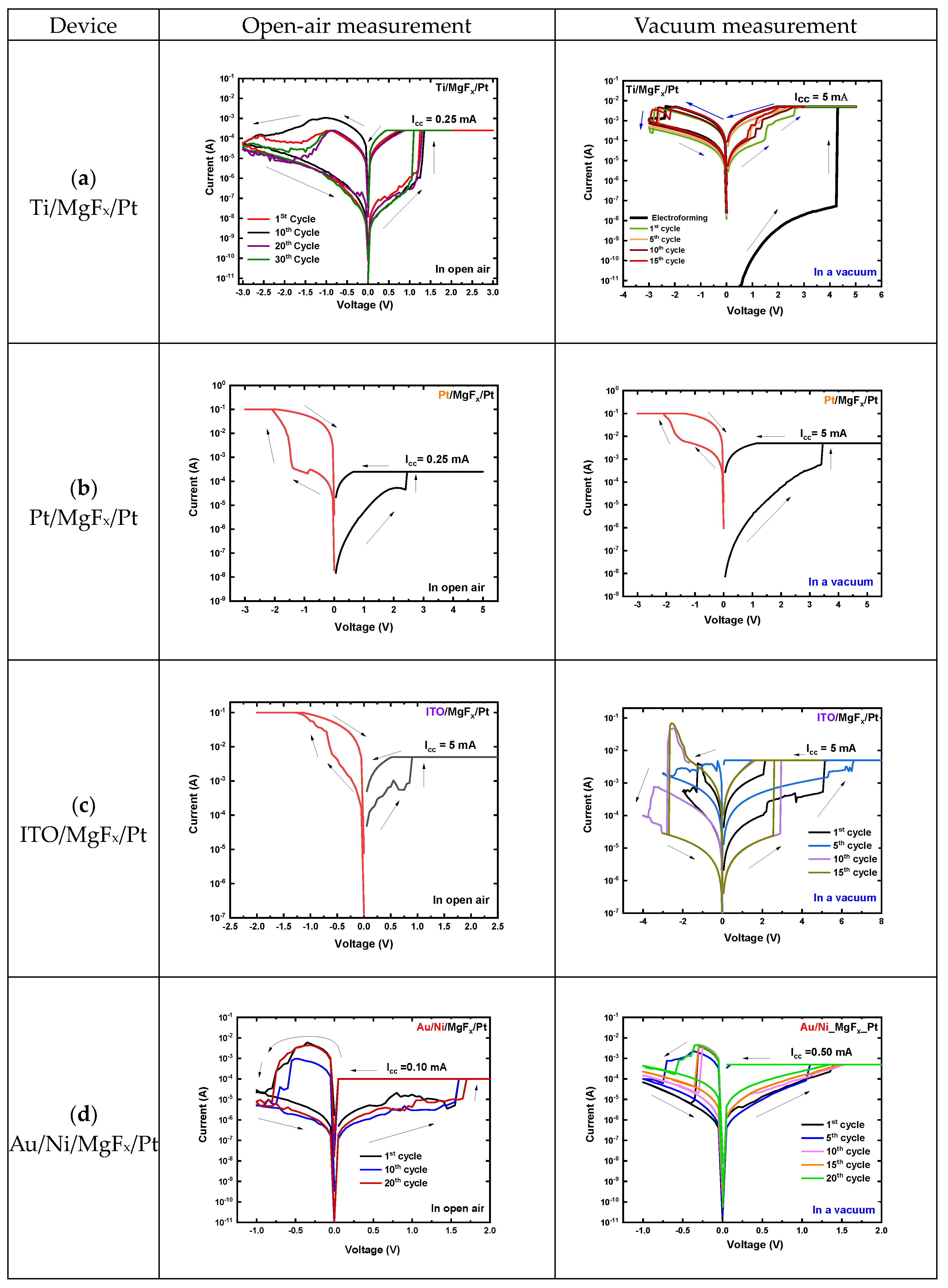
Figure 1. Typical I-V characteristics of MgFx-based RRAM devices in open-air environment and vacuum. (a) Ti/MgFx/Pt (b) Pt/MgFx/Pt, (c) ITO/MgFx/Pt, and (d) Au/Ni/MgFx/Pt.
Nanomaterials 13 01127 g001
Figure 2. Typical I-V characteristics of in open-air and vacuum. (a) Ti/MgFx/Pt (b) Ti/MgFx/ITO, (c) Ti/MgFx/n+-Si, and (d) Ti/MgFx/p+-Si.
Nanomaterials 13 01127 g002
Figure 3. The devices properties with work function differences of TE and BE. (a) VSET and VRESET in open air, (b) VSET and VRESET in a vacuum, (c) ILRS and IHRS in open air, and (d) ILRS and IHRS in a vacuum.
Nanomaterials 13 01127 g003
Figure 4. Data retention characteristics of Ti/MgFx/p+-Si memory devices. (a) In open-air environment; (b) in a vacuum environment.
Nanomaterials 13 01127 g004
Figure 5. Surface roughness (a) the p+-Si, (b) MgFx on p+-Si (c) Pt, (d) MgFx on Pt. Area is 10 μm × 10 μm.
Nanomaterials 13 01127 g005
Figure 6. Log (I)–log (V) characteristics of Ti/MgFx/p+-Si memory devices with slopes of different parts. (a) In an open-air environment; (b) in a vacuum environment.
Nanomaterials 13 01127 g006
Figure 7. Schematics of proposed switching mechanism of Ti/MgFx/p+-Si memory device.
Nanomaterials 13 01127 g007
Table 1. The work functions of the electrode materials.
Electrode
Materials
TiPtITOAuNin+-Sip+-Si
Work functions (eV)4.335.124.55.15.014.585.03
Table 2. The work function difference between TE and BE of devices.
DeviceTi
MgFx
Pt
Pt
MgFx
Pt
ITO
MgFx
Pt
Au/Ni
MgFx
Pt
Ti
MgFx
ITO
Ti
MgFx
n+-Si
Ti
MgFx
p+-Si
Work function difference (eV)0.7900.620.110.120.150.70
Table 3. Surface roughness of substrate and BEs.
Substrate and BE SiO2 Pt p+-Sin+-SiITO Coated Glass
Roughness, RMS (nm)0.9281.7010.2500.1974.050
Disclaimer/Publisher’s Note: The statements, opinions and data contained in all publications are solely those of the individual author(s) and contributor(s) and not of MDPI and/or the editor(s). MDPI and/or the editor(s) disclaim responsibility for any injury to people or property resulting from any ideas, methods, instructions or products referred to in the content.