Article

Electrochemical Determination of Uric Acid Using a Nanocomposite Electrode with Molybdenum Disulfide/Multiwalled Carbon Nanotubes (MoS2@MWCNT)

1
Departamento de Química de los Materiales, Facultad de Química y Biología, Universidad de Santiago de Chile (USACH), Santiago 9170002, Chile
2
Facultad de Química e Ingeniería Química, Universidad Nacional Mayor de San Marcos, Lima 15081, Peru
*
Authors to whom correspondence should be addressed.
Nanomaterials 2024, 14(11), 958; https://doi.org/10.3390/nano14110958
Submission received: 19 April 2024 / Revised: 11 May 2024 / Accepted: 22 May 2024 / Published: 30 May 2024
(This article belongs to the Special Issue Carbon Nanomaterials for Electrochemical Applications)

Abstract

:
This paper presents an application for a molybdenum disulfide nanomaterial with multiwalled carbon nanotubes (MoS2@MWCNT/E) in a modified electrode substrate for the detection of uric acid (UA). The modified electrode generates a substantial three-fold increase in the anodic peak current for UA compared to the unmodified MWCNT electrode (MWCNT/E). The MoS2@MWCNT/E surface was characterized by cyclic voltammetry (CV), scanning electron microscopy (SEM), energy-dispersive spectroscopy (EDS) and electrochemical impedance spectroscopy (EIS). The achieved detection limit stood at 0.04 µmol/L, with a relative standard deviation (RSD) of 2.0% (n = 10). The method’s accuracy, assessed through relative error and percent recovery, was validated using a urine standard solution spiked with known quantities of UA.

1. Introduction

UA is a product of purine metabolism in humans, which is the species with the highest levels of uric acid in urine and blood among mammals. Normal UA levels in adults are between 3.5 and 7.2 mg/dL [1]. Several reviews have been published about the effect of high levels of uric acid on people’s health. One of the first studies, from 2015, reports on the causes and treatment of gout, hyperuricemia, and the elimination of urate crystals [2]. Another review from 2017 deals with the pathogenic potential of uric acid, describing uric acid as a substance linked to diseases such as chronic inflammatory arthritis and gout and indicating that, as the predominant anti-oxidant molecule in plasma, uric acid is necessary for inducing immune responses [3]. In addition, a review conducted in 2021 addresses uric acid and cardiovascular diseases such as hypertension, atrial fibrillation, chronic kidney disease, heart failure and coronary artery disease [4]. These previous studies reveal the reasons for the current interest in UA and the need to develop new methodologies for its detection in biological samples. To this end, in 2020, a review explored the latest progress in the detection of UA as well as the history of the development of UA detection methods, which include spectral techniques (ultraviolet absorption, fluorescence), electrochemical approaches (voltammetry, electrochemiluminescence, surface plasmon resonance), chromatography (liquid and gas phase), capillary electrophoresis and isotope dilution mass spectrometry. One of the disadvantages of these techniques is their high cost [5]. Electroanalytical techniques have also begun to be used significantly in the last decade for the detection of UA due to their low cost. One of the first reviews published in 2011 concluded that the commonly most used substances for the development of electrochemical sensors for UA are nanoparticles, carbon nanotubes, polymers, and conducting polymers, which have detection limits very similar to those achieved by other, more expensive techniques [6]. A study from 2022 compares enzymatic and non-enzymatic electrodes for the detection of UA [7], in which the non-enzymatic electrode with the fewest reports is the one that uses MoS2 in the modification. Some reports use Al with MoS2 [8], graphene and indium tin oxide [9], poly(3,4-ethylenedioxythiophene) [10] or graphene [11], achieving detection limits between 1.1 and 0.14 µmol/L, respectively. In this context, MoS2 is a two-dimensional (2D) nanomaterial whose structure consists of two-dimensional S-Mo-S nanosheets chemically linked by van der Waals interactions [12]. Single-layer molybdenum disulfide (SLMoS2) or multilayer molybdenum disulfide (FLMoS2) were found, of which SLMoS2 has a specific surface area that improves conductivity [12]. In turn, FLMoS2 has spaces between layers that allow heavy metal cations to be intercalated, thus improving the adsorption and capture capacity of these cations [13]. FLMoS2 can also be employed in sonication-assisted exfoliation treatment with some solvents, generating SLMoS2 which has a large number of active sites that increase its electron transfer capacity, is difficult to oxidize, and has an ultrathin plane structure where electrons are confined to a plane of atomic thickness and therefore become sensitive to the environment [14]. In addition, MoS2 has been used in the modification of electrodes to detect organic and biological substances such as bovine albumin [15], methionine [16], sulfamethoxazole [17] and catechol [18] and metal cations such as Pb [19,20], As [21] and Hg [22].
The described characteristics of this nanomaterial and its recent use in the modification of electrodes make it a viable alternative for the detection of uric acid. This new method is also simple, sensitive and easy to manufacture, and it shows selective activity for UA compared to dopamine and ascorbic acid. This new application has been well characterized, and the activity for AU has been well verified, where its sensitivity, stability and accuracy are mainly highlighted.

2. Materials and Methods

2.1. Reagents and Instruments

All solutions used in the electrochemical cell and solution preparations were obtained from Mili-Q water (heal force superseries PW ultra-pure water). H3PO4, NaH2PO4 and Na2HPO4 were purchased from Merck (Darmstadt, Germany). DP, AA, UA, K3/K4Fe(CN)6 and KCl were purchased from Sigma-Aldrich (Darmstadt, Germany). The FLMoS2 nanoflake solution and MWCNTs were purchased from Graphene Supermarket (Ronkonkoma, NY, USA). The synthetic urine standard used was SigMatrix Serum Diluent, an aqueous solution containing 2% recombinant human albumin. Cyclic voltammetry (CV) and square wave voltammetry (SWV) ESI measurements were performed with a Chi-instruments 620-C (Austin, TX, USA), while energy-dispersive spectroscopy (EDS) was performed using an FEI QUANTA FEG 250 (Tokyo, Japan) with a secondary electron detector. An Ag/AgCl electrode and a platinum wire from Chi-instruments (Austin, TX, USA) were used as reference and auxiliary electrodes, respectively. An Elma S 10 H ultrasound bath was employed for the preparation of the modified electrode.

2.2. Measurements

The electrochemical cell was completed with 9.0 mL of ultra-pure water, 0.5 mL of PBS and 250.0 µL of UA 5.0 mmol/L (0.25 mmol/L in solution) by CV. For all SWV studies, between 10.0 and 100.0 µL of UA at 0.50 mmol/L (between 0.1 and 1.0 µmol/L in solution) was used. The validity of the EIS data and subsequent equivalent circuit modeling were assessed using the AfterMath data organizer (version 1.6.10523) software. Data validity was verified through the Kramers–Kronig test, with a stringent criterion and a chi-square value below 0.01. For the simulations, a Randles cell model was initially employed, with additional circuit elements incorporated iteratively to enhance the goodness-of-fit by at least one order of magnitude in the chi-square value.

2.3. Sample Treatment

The human urine standard SigMatrix Serum Diluent—an aqueous solution used to evaluate the accuracy of UA detection—was spiked with known quantities of UA and did not require prior treatment before analysis. Only 0.5 and 1.0 mL of the standard were used. This amount was necessary to obtain a more complex matrix.

2.4. Preparation of MWCNTs and MoS2@MWCNT/E

The FLMoS2 nanosheets were exfoliated by assisted sonication for 30 s. Subsequently, 100 µL of N,N-dimethylformamide (DMF) was added to a 300 µL aliquot of this solution and exfoliated again for another 30 s. Furthermore, 100 mg of MWCNTs were weighed in an agate mortar and then homogeneously mixed with the exfoliated MoS2 solution and 20 µL of mineral oil to form the composite. This was compacted into a PVC cylinder with a 1.0 mm diameter and 7.0 cm length, with an internal steel wire as a conductor.

3. Results and Discussion

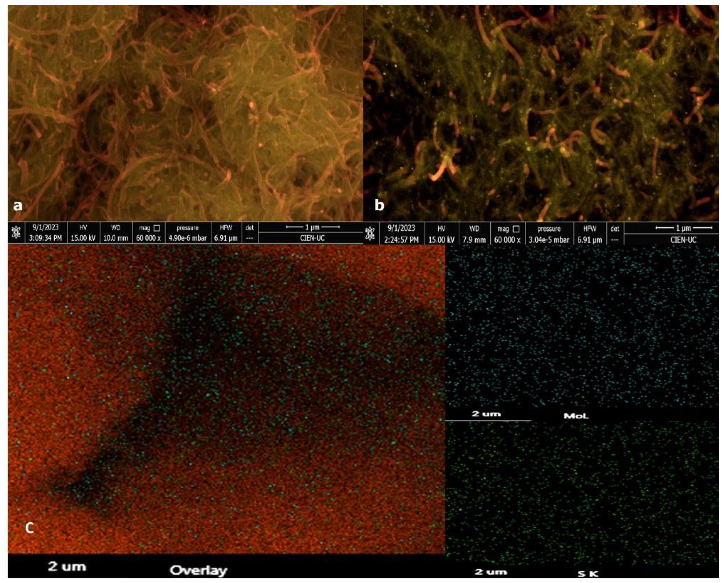
3.1. Surface Electrode Characterization

The surface morphology of SWCNT/E and modified MoS2@MWCNT/E was studied by SEM, EDX and EIS. Figure 1a,b show the SEM images for the surfaces of MWCNT/E and MoS2@MWCNT/E. The inset of Figure 1c shows the energy-dispersive X-ray (EDX) mapping of MoS2@MWCNT/E at the S Kα1 and Mo Lα1 energies.
MWCNTs display a fibrous surface that has a typical diameter in the range of 50–100 nm (Figure 1a). MoS2 nanosheets are homogeneously distributed over the entire surface of the MWCNTs. EDX studies showed that the MoS2 nanosheets are composed solely of Mo and S with very few impurities (inset of Figure 1c). Furthermore, Mo and S are observed with a homogeneous distribution on the surface of the MWCNTs. From this analysis, it can be confirmed that the MoS2 nanosheets deposited on the MWCNTs maintain their structure.
EIS was employed to examine alterations in the electrode–electrolyte interface. Figure 2 illustrates Nyquist diagrams for both the MWCNT/E and MoS2@MWCNT/E composites. Due to the porous nature of the electrodes, a constant-phase element (Q) was used instead of capacitors [Magar 2021]. The equivalent circuit model (ECM) for MWCNT/E consists of a Randles cell, which includes the following components: the electrolyte resistance (R1), the charge transfer resistance (R2), the double-layer capacitance (Q1), and a second constant-phase element (Q2), which accounts for surface reactivity and diffusion processes. And the ECM for MoS2@MWCNT/E includes the following components: the resistance of the solution (R1), the electrolytic resistance through the higher-resistance layer (R2), the capacity of the higher-resistance layer (Q1), the charge transfer resistance (R3), the capacitance of the electrical double layer (Q2) between the solution and the porous layer and a constant-phase element that accounts for diffusion-controlled processes (Q3) (Figure S1), with their respective values shown in Table S1. Surprisingly, the addition of MoS2 demonstrated a marked increase in the charge transfer resistance by almost eleven times, presented as a much larger semicircle when compared to that of MWCNT/E. This elevation can be attributed to its semiconductor properties, resulting in diminished conductivity compared to the inherently highly conductive pure MWCNTs [23,24]. This is in line with a previous report that showed a decrease in the charge transfer resistance upon MWCNT addition to MoS2 [25]. Owing to the electrode’s composition, the observed semicircle appears slightly elongated, prompting a representation as two semicircles in the equivalent circuit, while the absence of a clear separation suggests an embedded model. This proposition is further substantiated by the micrographs in Figure 1, which reveal the coexistence of MoS2 and nanotubes on the surface, suggesting intricate interactions between the electrolyte and both electrode constituents. However, the enhanced sensing performance and the higher electroactive surface area (ECSA) cannot be solely attributed to improved electrical conductivity. As previously reported, they are likely due to the electrocatalytic activity of MoS2 [8].

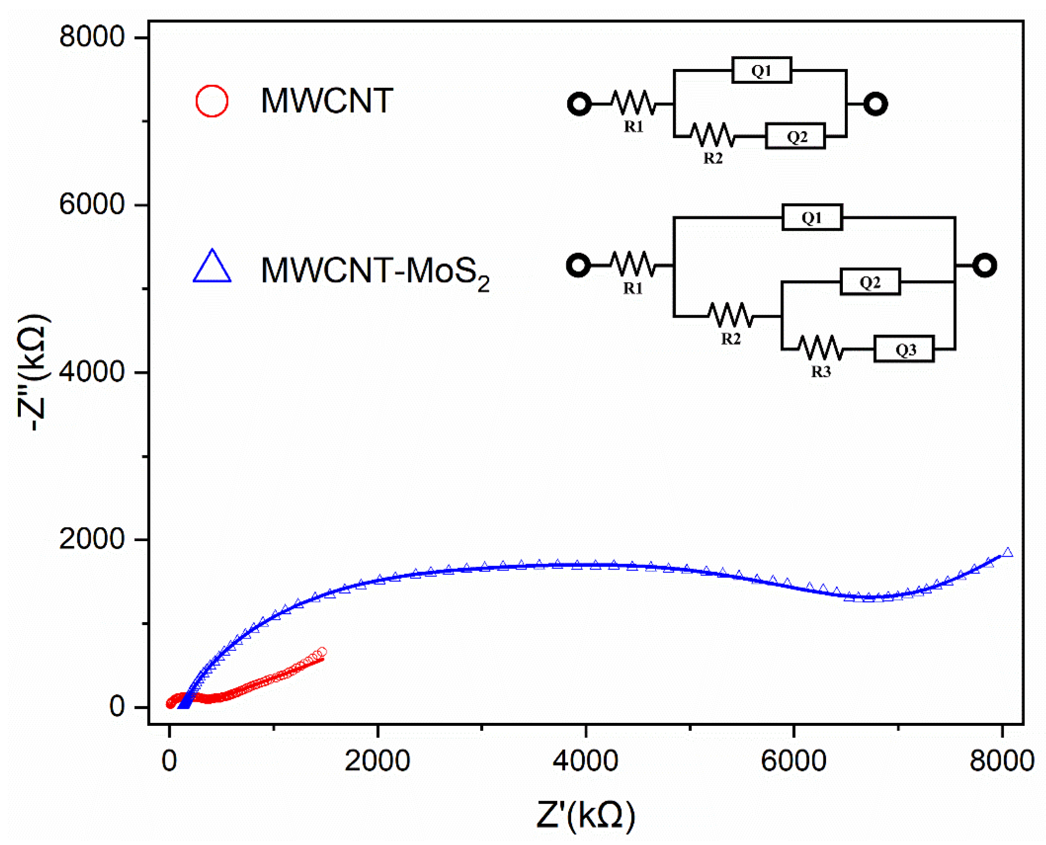
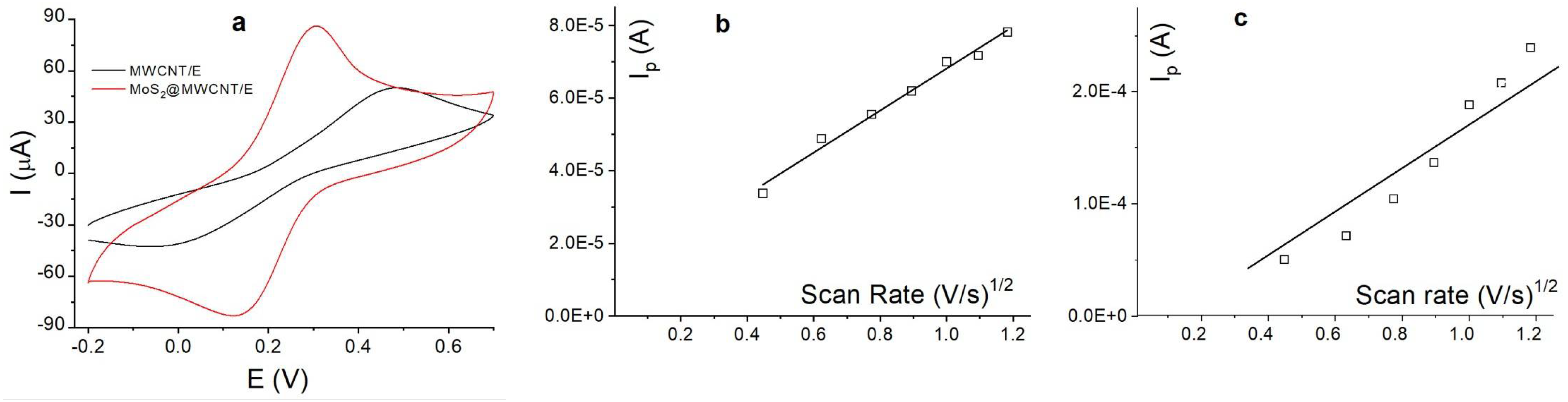
3.2. Electrochemical Characterization

The electroactive properties of MoS2@MWCNT/E were studied by CV. This technique allowed us to evaluate the active area surface. Figure 3 shows the cyclic voltammograms for a solution of 5.0 mmol/L of Fe(CN)63+/4+ with 0.1 mol/L of KCl and the voltammograms for the same solution when varying the scan rate between 0.02 and 0.14 V/s. In Figure 3a, the presence of MoS2 nanosheets in the MWCNT electrode was observed to considerably increase the current of the Fe(CN)63+/4+ redox system by more than two times. Furthermore, the Ipa/Ipc difference was almost 1.0. In turn, the ΔV changed from 0.50 V to 0.30 V (red curve in Figure 3a). These results show that the presence of MoS2 nanosheets improved the electrocatalytic activity of the MWCNTs.
Figure 3b,c show plots of the effect of the anodic and cathodic peak currents as a function of the square root of the scan rate (ν)1/2. The results show that by proportionally increasing (ν)1/2 between 0.02 and 0.140 V/s, the anodic and cathodic peak currents increase proportionally for both electrodes. Furthermore, the values of the anodic and cathodic peak currents’ slopes were higher for MoS2@MWCNT/E. This increase in the currents indicates that the active surface area is larger in the modified electrode. The slope values, Ip(A)/(ν)1/2, are summarized in Table 1. The active area of the electrode in cm2 was calculated for both electrodes using the Randles–Ševčík equation, which is summarized in Table 1. The results show that the active area of the electrode modified with MoS2 increased by almost 100%, and this increase may be one of the causes of the changes in the potential and current of the Fe(CN)63+/+4 system observed in Figure 3a. In the case of other electrodes modified with MoS2@MWCNTs and other substances such as 5-sulfosalicylic acid, a ΔV close to 0.10 V is reported for the Fe(CN)63+/4+ system. There are very few reports on the studied electrodes modified with MoS2 and MWCNTs in the presence of Fe(CN)63+/4+ that have calculated the active area value. In relation to the value calculated in this paper, the active area value is much smaller compared to other larger-diameter electrodes, in which the reproduced active area is normally greater than 0.10 cm2 in electrodes modified with metal cation oxides and nanoparticles [26].

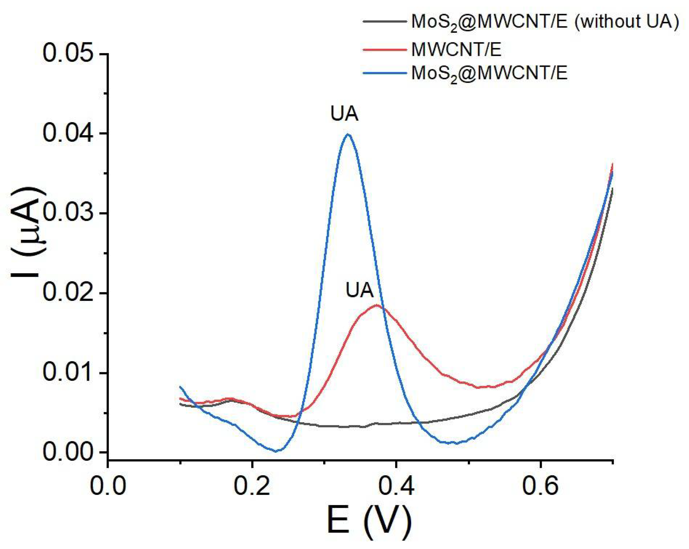
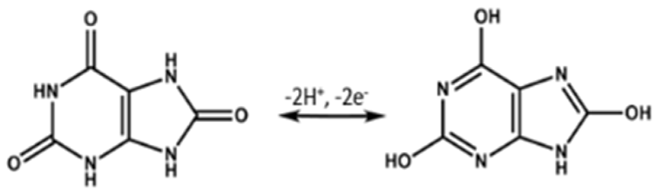
3.3. Electrochemical Activity of UA with MoS2@MWCNT/E

Figure 4 shows the square wave voltammograms for UA using MWCNT/E and MoS2@MWCNT/E, where anodic peak currents were observed at 0.37 V with MWCNT/E and 0.33 V with MoS2 nanoflakes. This result indicates that the presence of MoS2 in the MWCNT electrode means less energy is required for the oxidation of UA. Additionally, the current increases by almost three times compared to the unmodified electrode. This increase may be due to the increase in surface area calculated in the previous section but also to the electrostatic interactions and biocompatibility between UA and MoS2, which allow the amount of UA on the electrode surface to be greater [9]. In relation to the value of the oxidation potential of UA, in other electrodes modified with MoS2 and conductive polymers such as PEDOT [10], carbon nanomaterials such as graphene [11] or Al foil [8], the observed potential is very similar, below 0.4 V. Meanwhile, with Au nanoparticles, the potential observed displays higher values of 0.40 V [27]. Therefore, in this new report, the modified electrode presents good activity and requires less energy to oxidize. The reaction can be attributable to the oxidation of the nitro group of AU (Scheme 1) [28].

3.4. pH Effect

UA presents a pKa value of 5.4, exhibiting the behavior of a weak acid [29]. Therefore, the pH of the UA solution affects its oxidation–reduction behavior. To assess the effect of pH on the anodic peak currents and the anodic potentials’ peak of UA using MoS2@MWCNT/E, voltammetry measurements were developed at different pH values that ranged between 2.0 and 6.0 using PBS. The results are shown in Figure 5, where it is clearly observed that at more acidic pH values, the anodic currents are stronger (Figure 5a). It is possible that at pH values between 5.0 and 6.0, the currents are lower because these are pH values very close to the pKa value of UA; consequently, UA is chemically oxidized and competes with electrochemical oxidation. In addition, the potential values shift to more positive values when the pH values are more acidic, indicating that UA has a Nernstian behavior and that the potential depends on the pH value. The plot of Ep(V) vs. pH (Figure 5b) presented a negative slope value of −0.050 pH. This slope value is close to the theoretical value of 0.059 pH, indicating that the number of protons (H+) involved in the reaction is equal to the number of electrons (e). Previous reports have shown almost the same slope value using other electrodes and suggested an equal stoichiometry of 2H+:2e [30]. In general, using electrodes modified with MoS2, the pH value reported with the highest value of anodic current for UA is almost neutral [10,11,27]. A pH value of 2.0 was chosen as optimal because the current is much higher.

3.5. Parameter Optimization

The parameters that directly influence the increase in the anodic current of UA, like the pH studied in Section 3.2, were the anodic peak currents, which increased from 0.02 to 0.05 µA when the pH values changed from 5.0 to 2.0, respectively. Additionally, the accumulation time (tACC) and accumulation potential (EACC) were studied in the deposit stage. Figure 5 shows the peak currents as a function of EACC (Figure 6a) and tACC (Figure 6b). It is clearly observed that the anodic peak current increases proportionally with an increase in EACC between 0.40 and 0.60 V. At higher potential values, the anodic peak currents decrease proportionally. A value of 0.6 V is close to the oxidation potential observed for UA. Therefore, at higher potential values, the current decreases due to UA undergoing electro-oxidation processes on the electrode surface in the deposit stage. Meanwhile, the optimal tACC was 50.0 s. At higher values, the current decreases proportionally, possibly due to the saturation of the electrode surface. A potential of 0.6 V for 50 s was chosen as optimal in the accumulation stage. In the stripping stage, the parameters’ frequency and pulse amplitude were 15.0 Hz and 0.025 V, respectively. With the optimized parameters of pH, EACC and tACC, the anodic peak current increased from 0.02 µA to 0.08 µA, an increase of almost 75% of the anodic peak current for UA.

3.6. Scan Rate Effect on UA Using MoS2@MWCNT/E

Studying the transport mechanism of the analyte on the electrode surface is crucial to calculating the useful life of the electrode because the adsorption processes limit the use of the modified electrode in several measurements due to the analyte adsorbed on the surface of the electrode undergoing memory processes. Additionally, diffusion-controlled processes allow for the use of the electrode in more measurements.
The mass transport mechanism was studied by CV, verifying the anodic peak current for UA as a function of the scan rate between 0.02 and 0.14 V/s. Figure 7 shows the cyclic voltammograms and the plots of Ip (µA) vs. the square root of the scan rate and log Ip (µA) vs. the log scan rate. The results show that the anodic current increases proportionally as the square root of the scan rate increases between 0.02 and 0.14 V/s, and the linear relationship presents an R2 of 0.991. Furthermore, the slope of the plot of log Ip (µA) vs. the log scan rate (V/s) has a value of 0.453. These results indicate that the process is controlled by diffusion. Repetition studies showed that the same electrode can be used up to 10 times without considerable changes in its activity. In this case, the difference between the first and the tenth measurement was 0.0018 µA, indicating a decrease of 1.8 × 10⁻⁴ µA for each measurement. The relative standard deviation (RSD) was 0.0001, and the coefficient of variation (%CV) was 2.0%.

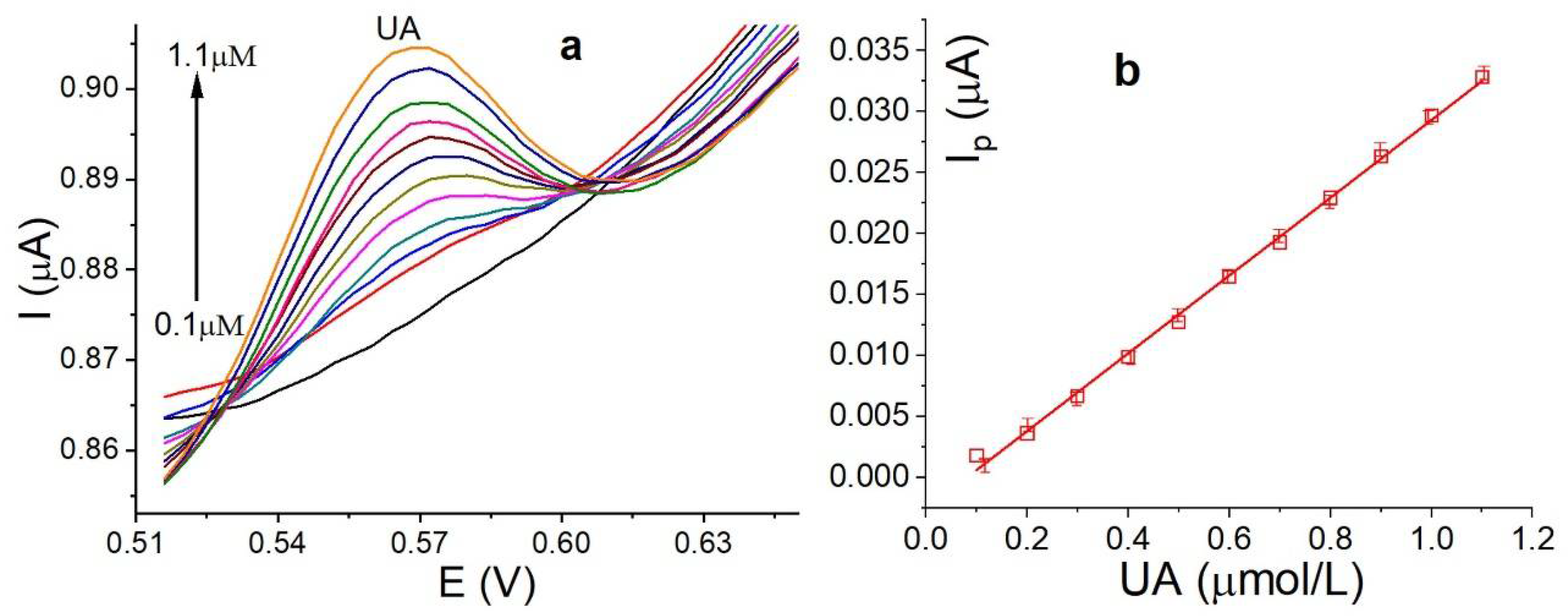
3.7. Calibration Curve, Detection Limits and Reproducibility

The calibration curve was developed by SWV within the concentration range of 0.10–1.1 µmol/L of UA using MoS2@MWCNT/E and under the following optimal parameters: EStep: 0.01 V; EAMP: 0.025 V; frequency: 15 Hz, EACC: 0.60 V; tACC: 50.0 s, and PBS pH: 2.0. The voltammograms and calibration curves are shown in Figure 8. The current ranges between each standard are small due to the small electrode diameter of 1.0 mm. The detection limit is 0.04 µmol/L, which was compared with previous reports using electrodes modified with MoS2 nanoflakes, as summarized in Table 2. The detection limit reported in this work is equally acceptable compared to more complex electrodes.

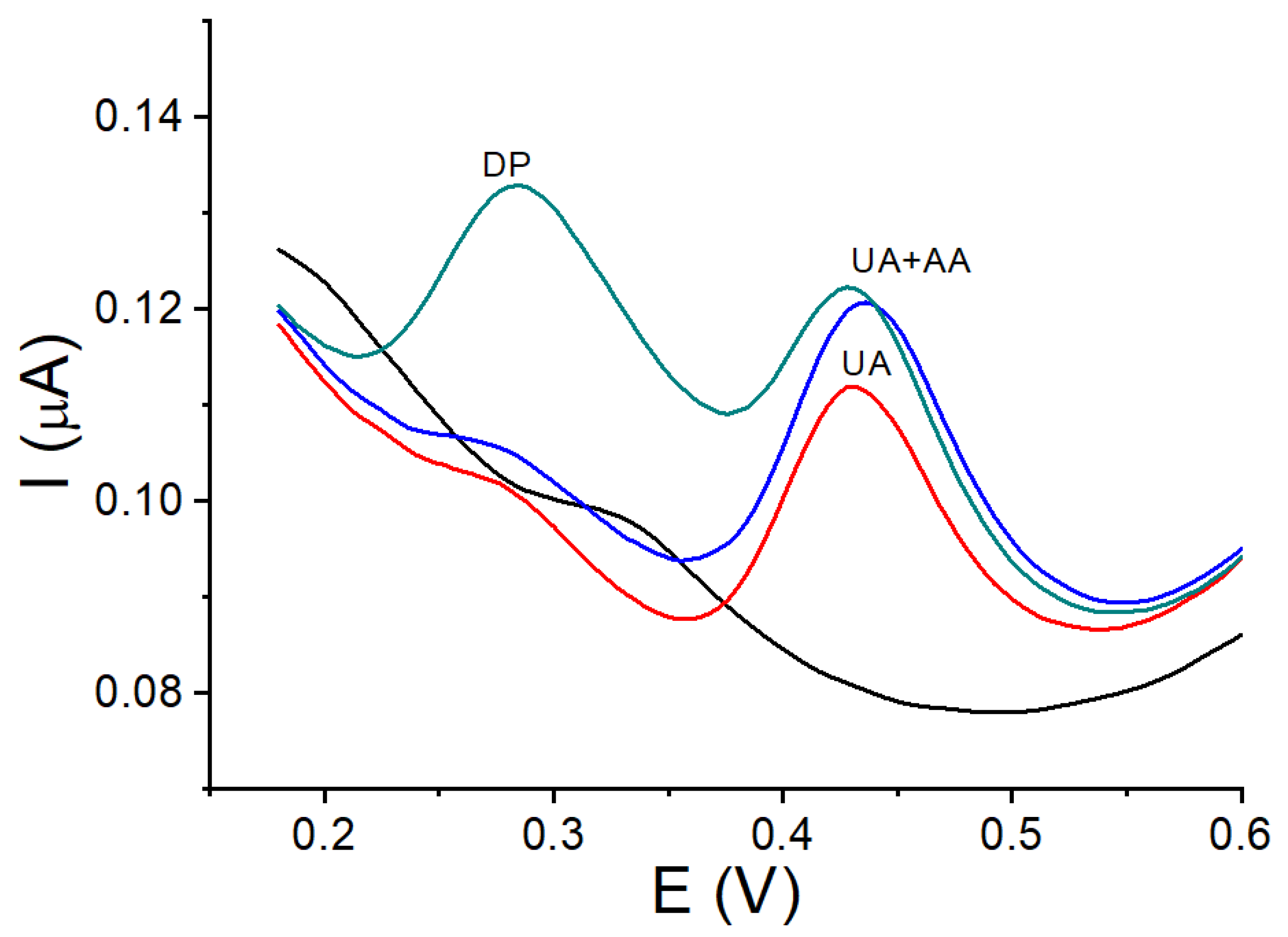
3.8. Interference Study with DP and AA

Substances that may cause some type of interference with the UA anodic current were considered and evaluated. Substances such as glucose, proteins, ascorbic acid (AA), dopamine (DP) and heavy metal cations were evaluated. Only DP and AA showed activity with MoS2@MWCNT/E. The voltamperograms of UA, DP and AA are shown in Figure 9 The results show that DP is oxidized at a less positive power value close to 0.30 V (green curve). In turn, the UA signal (red curve) presents an increase in the anodic current when AA is added (blue curve). This result indicates that AA is oxidized at the same potential value observed for UA, but the increase is smaller compared to the increase observed for UA alone. Furthermore, an increase in the background current (blue curve) was observed that makes the increase in the anodic current of UA appear greater, but in reality, the increase in the anodic current for UA was 10.0% in the presence of AA. These results indicate that the detection of UA is better without the presence of AA.

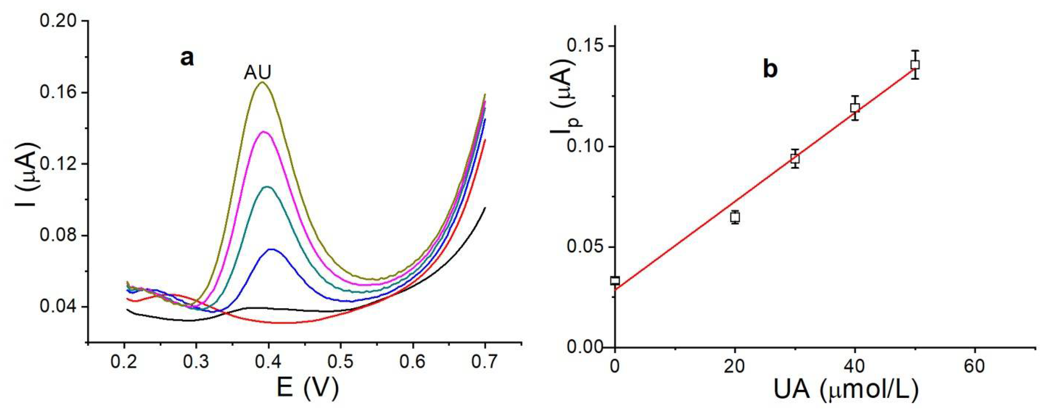
3.9. Analytical Application

The actual utility of MoS2@MWCNT/E was evaluated using the urine standard synthetic SigMatrix Serum Diluent, an aqueous solution containing 2% recombinant human albumin (expressed in rice) in a phosphate buffered saline solution (pH 7.4) with 0.1% ProClin™ 950, spiked with 10.0 µmol/L of UA (Figure 10). The analyses were developed using the standard addition method. The average UA quantified was 11.2 ± 0.01 µmol/L, with a relative error (%ER) of 12.0%. In this test, measurements were performed with concentrations higher than those in Figure 8. Additionally, the UA potential value was observed at less positive values than those observed in previous studies, possibly due to a matrix effect in the sample. These results demonstrate the good accuracy of the new method.

4. Conclusions

In this new study, the authors present a new convenient method for the detection of UA biological samples using an electrode based on MoS2 nanosheets on MWCNTs through a simple modification process. The modified surface showed excellent electrochemical activity for UA, allowing for a detection limit below 0.10 µmol/L. The characterization of the surface was comprehensive. Several techniques, such as scanning electron microscopy (SEM), dispersive X-ray spectroscopy (EDS), electrical impedance spectroscopy (EIS) and cyclic voltammetry (CV), were employed to measure the electrochemistry behavior of the modified electrodes towards UA oxidation. The notable advantages of the MoS2-modified electrode are its ease of fabrication, reproducibility and stability. One of its few disadvantages is its low selectivity in the presence of ascorbic acid.

Supplementary Materials

The following supporting information can be downloaded at https://www.mdpi.com/article/10.3390/nano14110958/s1: Figure S1: Physical model and equivalent circuits used for modeling the impedance spectra of MWCNT/E (left) and MoS2@MWCNT/E (right); Table S1: Circuit elements’ values in the modeled circuit obtained from the Nyquist diagram in Figure 2.

Author Contributions

Conceptualization, J.P.-L. and R.S.; methodology, J.P.-L., R.S., F.R. and A.P.d.l.V.; software, J.P.-L., F.R. and B.P.; validation, J.P.-L. and E.N.; formal analysis, J.P.-L., F.R. and F.L.; investigation, J.P.-L., R.S., F.R. and A.P.d.l.V.; resources, J.P.-L. and F.R.; data curation, E.N., J.P.-L., R.S., B.P. and F.L.; writing—original draft preparation, E.N., R.S., J.P.-L. and F.R.; writing—review and editing, E.N., R.S. and F.R.; visualization, J.P.-L., R.S. and E.N.; supervision, E.N. and R.S.; project administration, R.S.; funding acquisition, R.S. and E.N. All authors have read and agreed to the published version of the manuscript.

Funding

The research was funded by FONDECYT grant project 1230628 and UNMSM grant project C24070371.

Data Availability Statement

Data are contained within the article.

Acknowledgments

R.S. thanks FONDECYT for its financial support (project 1230628), and E.N. is thankful for the financial support from the Office of the Vice-President of Research from Universidad Nacional Mayor de San Marcos (project C24070371 004305-R-24).

Conflicts of Interest

The authors declare no conflicts of interest.

References

  1. Desideri, G.; Castaldo, G.; Lombardi, A.; Mussap, M.; Testa, A.; POntremoli, R.; Punzi, L.; Borghi, C. Is it time to revise the normal range of serum uric acid levels? Eur. Rev. Med. Pharmacol. Sci. 2014, 18, 1295–1306. [Google Scholar]
  2. Perez-Ruiz, F.; Dalbeth, N.; Bardin, T. A Review of Uric Acid, Crystal Deposition Disease, and Gout. Adv. Ther. 2015, 32, 31–41. [Google Scholar] [CrossRef] [PubMed]
  3. El Ridi, R.; Tallima, H. Physiological functions and pathogenic potential of uric acid: A review. J. Adv. Res. 2017, 8, 487–493. [Google Scholar] [CrossRef] [PubMed]
  4. Saito, Y.; Tanaka, A.; Node, K.; Kobayashi, Y. Uric acid and cardiovascular disease: A clinical review. J. Cardiol. 2021, 78, 51–57. [Google Scholar] [CrossRef] [PubMed]
  5. Wang, Q.; Wen, X.; Kong, J. Recent Progress on Uric Acid Detection: A Review. Crit. Rev. Anal. Chem. 2020, 50, 359–375. [Google Scholar] [CrossRef] [PubMed]
  6. Lakshmi, D.; Whitcombe, M.J.; Davis, F.; Sharma, S.P.; Prasad, B. Electrochemical Detection of Uric Acid in Mixed and Clinical Samples: A Review. Electroanalysis 2011, 23, 305–320. [Google Scholar] [CrossRef]
  7. Aafria, S.; Kumari, P.; Sharma, S.; Yadav, S.; Batra, B.; Rana, J.S.; Sharma, M. Electrochemical biosensing of uric acid: A review. Microchem. J. 2022, 182, 107945. [Google Scholar] [CrossRef]
  8. Sha, R.; Vishnu, N.; Badhulika, S. MoS2 based ultra-low-cost, flexible, nonenzymatic and non-invasive electrochemical sensor for highly selective detection of Uric acid in human urine samples. Sens. Actuators B Chem. 2019, 279, 53–60. [Google Scholar] [CrossRef]
  9. Guo, X.; Yue, H.; Song, S.; Huang, S.; Gao, X.; Chen, H.; Wu, P.; Zhang, T.; Wang, Z. Simultaneous electrochemical determination of dopamine and uric acid based on MoS2 nanoflowers-graphene/ITO electrode. Microchem. J. 2020, 154, 104527. [Google Scholar] [CrossRef]
  10. Li, Y.; Lin, H.; Peng, H.; Qi, R.; Luo, C. A glassy carbon electrode modified with MoS2 nanosheets and poly(3,4-ethylenedioxythiophene) for simultaneous electrochemical detection of ascorbic acid, dopamine and uric acid. Mikrochim. Acta 2016, 183, 2517–2523. [Google Scholar] [CrossRef]
  11. Xing, L.; Ma, Z. A glassy carbon electrode modified with a nanocomposite consisting of MoS2 and reduced graphene oxide for electrochemical simultaneous determination of ascorbic acid, dopamine, and uric acid. Mikrochim. Acta 2016, 183, 257–263. [Google Scholar] [CrossRef]
  12. Xu, Z.; Lu, J.; Zheng, X.; Chen, B.; Luo, Y.; Tahir, N.M.; Huang, B.; Xia, X.; Pan, X. A critical review on the applications and potential risks of emerging MoS2 nanomaterials. J. Hazard Mater. 2020, 399, 123057. [Google Scholar] [CrossRef] [PubMed]
  13. Sun, Y.-F.; Sun, J.-H.; Wang, J.; Pi, Z.-X.; Wang, L.-C.; Yang, M.; Huang, X.-J. Sensitive and anti-interference stripping voltammetry analysis of Pb (II) in water using flower-like MoS2/rGO composite with ultra-thin nanosheets. Anal. Chim. Acta 2019, 1063, 64–74. [Google Scholar] [CrossRef] [PubMed]
  14. Gan, X.; Zhao, H.; Quan, X. Two-dimensional MoS2: A promising building block for biosensors. Biosens. Bioelectron. 2017, 89, 56–71. [Google Scholar] [CrossRef]
  15. Kukkar, M.; Sharma, A.; Kumar, P.; Kim, K.-H.; Deep, A. Application of MoS2 modified screen-printed electrodes for highly sensitive detection of bovine serum albumin. Anal. Chim. Acta 2016, 939, 101–107. [Google Scholar] [CrossRef]
  16. Li, Y.; Mei, S.; Liu, S.; Hun, X. A photoelectrochemical sensing strategy based on single-layer MoS2 modified electrode for methionine detection. J. Pharm. Biomed. Anal. 2019, 165, 94–100. [Google Scholar] [CrossRef] [PubMed]
  17. Ramya, M.; Kumar, P.-S.; Rangasamy, G.; Shankar, V.-U.; Rajesh, G.; Nirmala, K. Experimental investigation of the electrochemical detection of sulfamethoxazole using copper oxide-MoS2 modified glassy carbon electrodes. Environ. Res. 2023, 216, 114463. [Google Scholar] [CrossRef] [PubMed]
  18. Zhang, Y.; Li, X.; Li, D.; Wei, O. A laccase based biosensor on AuNPs-MoS2 modified glassy carbon electrode for catechol detection. Colloids Surf. B Biointerfaces 2020, 186, 110683. [Google Scholar] [CrossRef] [PubMed]
  19. Guo, C.; Wang, C.; Sun, H.; Dai, D.; Gao, H. A simple electrochemical sensor based on rGO/MoS 2/CS modified GCE for highly sensitive detection of Pb (ii) in tobacco leaves. RSC Adv. 2021, 11, 29590–29597. [Google Scholar] [CrossRef] [PubMed]
  20. Shi, J.-J.; Zhu, J.-C.; Zhao, M.; Wang, Y.; Yang, P.; He, J. Ultrasensitive photoelectrochemical aptasensor for lead ion detection based on sensitization effect of CdTe QDs on MoS2-CdS:Mn nanocomposites by the formation of G-quadruplex structure. Talanta 2018, 183, 237–244. [Google Scholar] [CrossRef] [PubMed]
  21. Hu, H.; Hu, Y.; Xie, B.; Zhu, J. High Sensitivity Electrochemical As (III) Sensor Based on Fe3O4/MoS2 Nanocomposites. Nanomaterials 2023, 13, 2288. [Google Scholar] [CrossRef] [PubMed]
  22. Aswathi, R.; Sandhya, K.-Y. Ultrasensitive and selective electrochemical sensing of Hg(ii) ions in normal and sea water using solvent exfoliated MoS2: Affinity matters. J. Mater. Chem. A 2018, 6, 14602–14613. [Google Scholar] [CrossRef]
  23. Santa Ana, M.; Benavente, A.E.; Gómez-Romero, P.; González, G. Poly(acrylonitrile)–molybdenum disulfide polymer electrolyte nanocomposite. J. Mater. Chem. 2006, 16, 3107–3113. [Google Scholar] [CrossRef]
  24. Lau, C.-H.; Cervini, R.; Clarke, S.-R.; Markovic, M.-G.; Matisons, J.-G.; Hawkins, S.-C.; Huynh, C.-P.; Simon, G.-P. The effect of functionalization on structure and electrical conductivity of multi-walled carbon nanotubes. J. Nanoparticle Res. 2008, 10, 77–88. [Google Scholar] [CrossRef]
  25. Vijayaraj, K.; Dinakaran, T.; Lee, Y.; Kim, S.; Kim, H.; Lee, J.; Chang, S.-C. One-step construction of a molybdenum disulfide/multi-walled carbon nanotubes/polypyrrole nanocomposite biosensor for the ex-vivo detection of dopamine in mouse brain tissue. Biochem. Biophys. Res. Commun. 2017, 494, 181–187. [Google Scholar] [CrossRef] [PubMed]
  26. Nagles, E.; Cardenas-Riojas, A.A.; Anaya-Roa, F.; Roldán-Tello, L. Amperometric Method for Detecting Paracetamol using a Carbon Paste Electrode Modified with Vanadium (V) Oxide. ChemistrySelect 2024, 9, e202304770. [Google Scholar] [CrossRef]
  27. Panneer, S.-S.; Hansa, M.; Yun, K. Simultaneous differential pulse voltammetric detection of uric acid and melatonin based on a self-assembled Au nanoparticle–MoS2 nanoflake sensing platform. Sens. Actuators B Chem. 2020, 307, 127683. [Google Scholar] [CrossRef]
  28. Teferaa, M.; Tessemab, M.; Admassieb, S.; Wubeta, W. Voltammetric determination of uric acid using multiwall carbon nanotubes coated-poly(4-amino-3-hydroxy naphthalene sulfonic acid) modified glassy carbon electrode. Heliyon 2021, 7, 07575. [Google Scholar] [CrossRef]
  29. Finlayson, B.; Smith, A. Stability of first dissociable proton of uric acid. J. Chem. Eng. Data 1974, 19, 94–97. [Google Scholar] [CrossRef]
  30. Tamayo, L.-V.; Torres, J.-F.; Llanos-Penagos, J.; Calderón, J.-A.; Nagles, E.; García-Beltrán, O.; Hurtado, J.-J. Sensitive and profitable electrochemical detection of uric acid in the presence of dopamine with a novel carbon paste electrode decorated with a copper (II) complex. Electroanalysis 2019, 31, 2429–2436. [Google Scholar] [CrossRef]
Figure 1. SEM images: (a) MWCNT/E, (b) MoS2@MWCNT/E and (c) EDX mapping of MoS2@MWCNT/E at the S Kα1 and Mo Lα1 energies.
Nanomaterials 14 00958 g001
Figure 2. Nyquist diagrams of MWCNT/E and MoS2@MWCNT/E with equivalent circuit models as insets. The lines represent the fitted model. Frequency range: 100,000.0–0.1 Hz. Solution composition: 0.05 M of Fe(CN)63+/4+ with 0.1 M of KCl. Potential: 0.01 V.
Nanomaterials 14 00958 g002
Figure 3. (a) Cyclic voltammograms of Fe(CN)63+/4+ (5.0 mmol/L) at a scan rate of 0.05 V/s with MWCNT/E (black curve) and MoS2@MWCNT/E (red curve) and plots of the square root of the scan rate vs. anodic and cathodic peak currents for MWCNT/E (b) and MoS2@MWCNT/E (c).
Nanomaterials 14 00958 g003
Figure 4. Square wave voltammograms of UA (1.0 µmol/L) with MWCNT/E (red line) and MoS2@MWCNT/E without UA (black line) and with UA (blue curve). Experimental Conditions: PBS: pH 7.0; EACC: 0.0 V; tACC: 30.0 s.
Nanomaterials 14 00958 g004
Scheme 1. UA electro-oxidation reaction.
Nanomaterials 14 00958 sch001
Figure 5. (a) Square wave voltammograms of UA using MoS2@MWCNT/E in PBS with a pH between 2.0 and 6.0 and (b) plot of Ep(V) vs. pH. Experimental conditions: UA (1.0 µmol/L); EACC: 0.0 V; tACC: 30.0 s.
Nanomaterials 14 00958 g005
Figure 6. (a) Plot of Ip (µA) vs. EACC (V) and (b) plot of Ip (µA) vs. tACC (s) using MoS2@MWCNT/E. Experimental conditions: UA (1.0 µmol/L); pH: 2.0 in PB; frequency: 15 Hz; and pulse amplitude: 0.025 V.
Nanomaterials 14 00958 g006
Figure 7. (a) Cyclic voltammograms of UA with MoS2@MWCNT/E; (b) plot of Ip (µA) vs. ν1/2 (V/s); and (c) plot of log Ip (µA) vs. log ν (V/s). Experimental conditions: UA (0.25 mmol/L); scan rate: between 0.02 and 0.14 V/s; and pH 2.0 in PBS.
Nanomaterials 14 00958 g007
Figure 8. (a) Square wave voltammograms and (b) corresponding calibration curves depicting UA concentrations ranging from 0.10 to 1.1 µmol/L using MoS2@MWCNT/E. Experimental conditions: pH: 2.0; Estep: 0.010 V; Eamp; 0.025 V; EACC: 0.6 V; tACC; 50.0 s; and frequency: 15.0 Hz.
Nanomaterials 14 00958 g008
Figure 9. Square wave voltammograms for UA (red curve), UA–AA (blue curve) and UA–AA–DP (green curve). A concentration of (A) 1.0 mmol/L at pH 3.0 with MoS2@MWCNT/E. Experimental conditions are similar to those in Figure 8.
Nanomaterials 14 00958 g009
Figure 10. (a) Square wave voltammograms and (b) corresponding calibration curve depicting UA concentrations ranging from 10.0 to 50.0 µmol/L using MoS2@MWCNT/E. Experimental conditions: pH: 2.0; Estep: 0.010 V; Eamp; 0.025 V; EACC: 0.6 V; tACC; 50.0 s; and frequency: 15.0 Hz.
Nanomaterials 14 00958 g010
Table 1. Active surface areas of MWCNT/E and MoS2@MWCNT/E.
ElectrodeSlope (Ip½)Area (cm2)Total Area (cm2)
IpaIpcIpaIpc
MWCNT/E5.8 × 10−51.4 × 10−50.0150.0040.019
MoS2@MWCNT/E2.7 × 10−42.8 × 10−50.0750.0720.079
Table 2. Modified electrodes with MoS2 for UA.
ElectrodeApplicationLoD (µmol/L)Ref.
MoS2/Al foilUrine1.190[8]
MoS2-rGO/ITOUrine0.140[9]
MoS2-PEDOT/GCEUrine0.950[10]
AuNP-MoS2/GCEUrine0.018[27]
MoS2/rGO/GCESerum1.590[11]
MoS2@MWCNT/EUrine0.040This work
Disclaimer/Publisher’s Note: The statements, opinions and data contained in all publications are solely those of the individual author(s) and contributor(s) and not of MDPI and/or the editor(s). MDPI and/or the editor(s) disclaim responsibility for any injury to people or property resulting from any ideas, methods, instructions or products referred to in the content.

