Corrosion Behavior of 20G and TP347H in Molten LiCl-NaCl-KCl Salt

 , , ,
, , ,
Abstract
:1. Introduction
2. Materials and Methods
2.1. Materials
2.2. Corrosion Experiment
2.3. Analysis Method
3. Results
3.1. Corrosion Performance of Alloy Specimens in Molten Salt
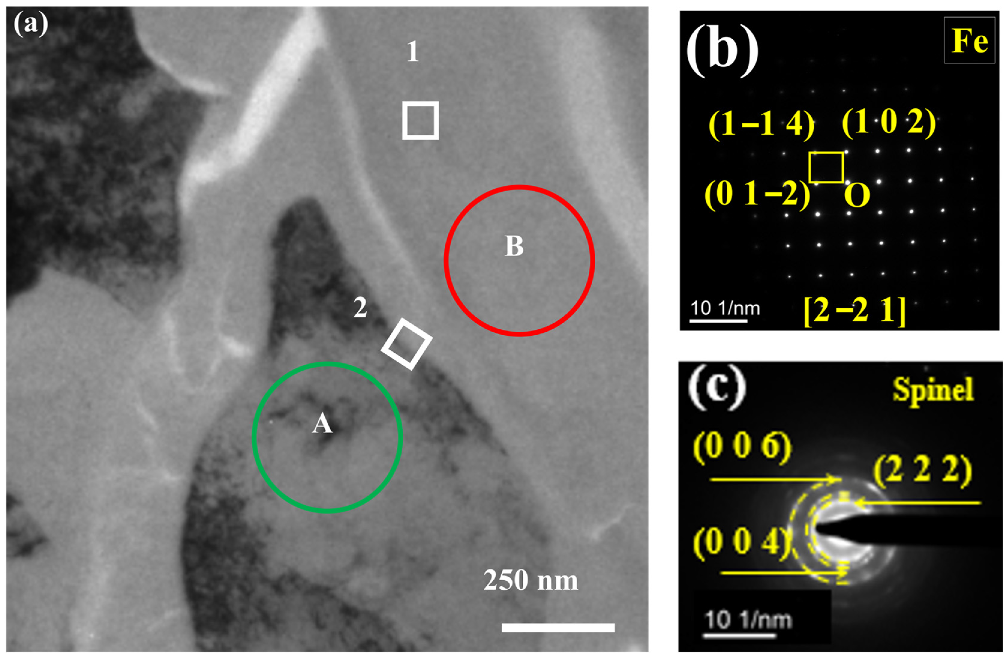
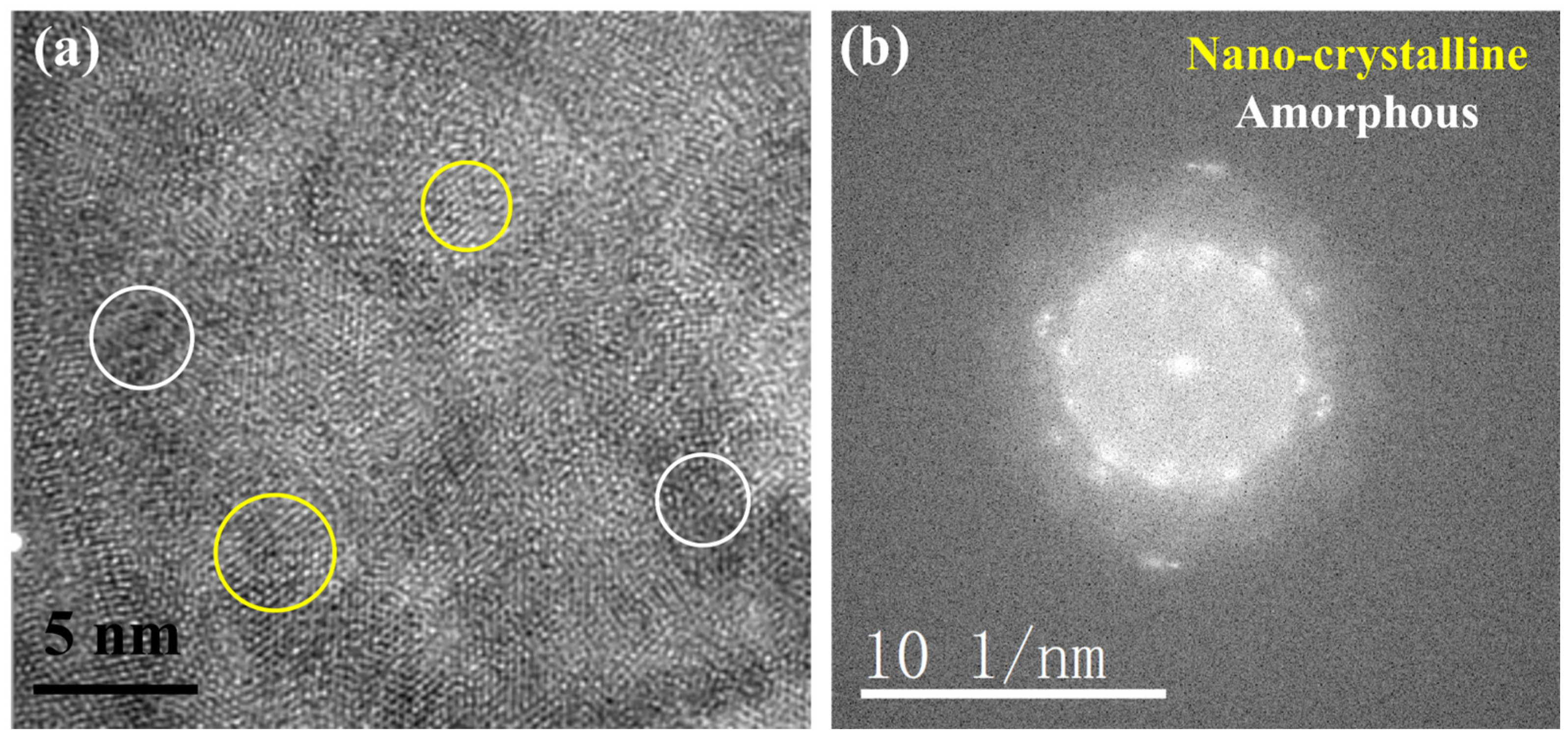
3.2. TEM Analysis of TP347H
4. Discussion
5. Conclusions
- (1)
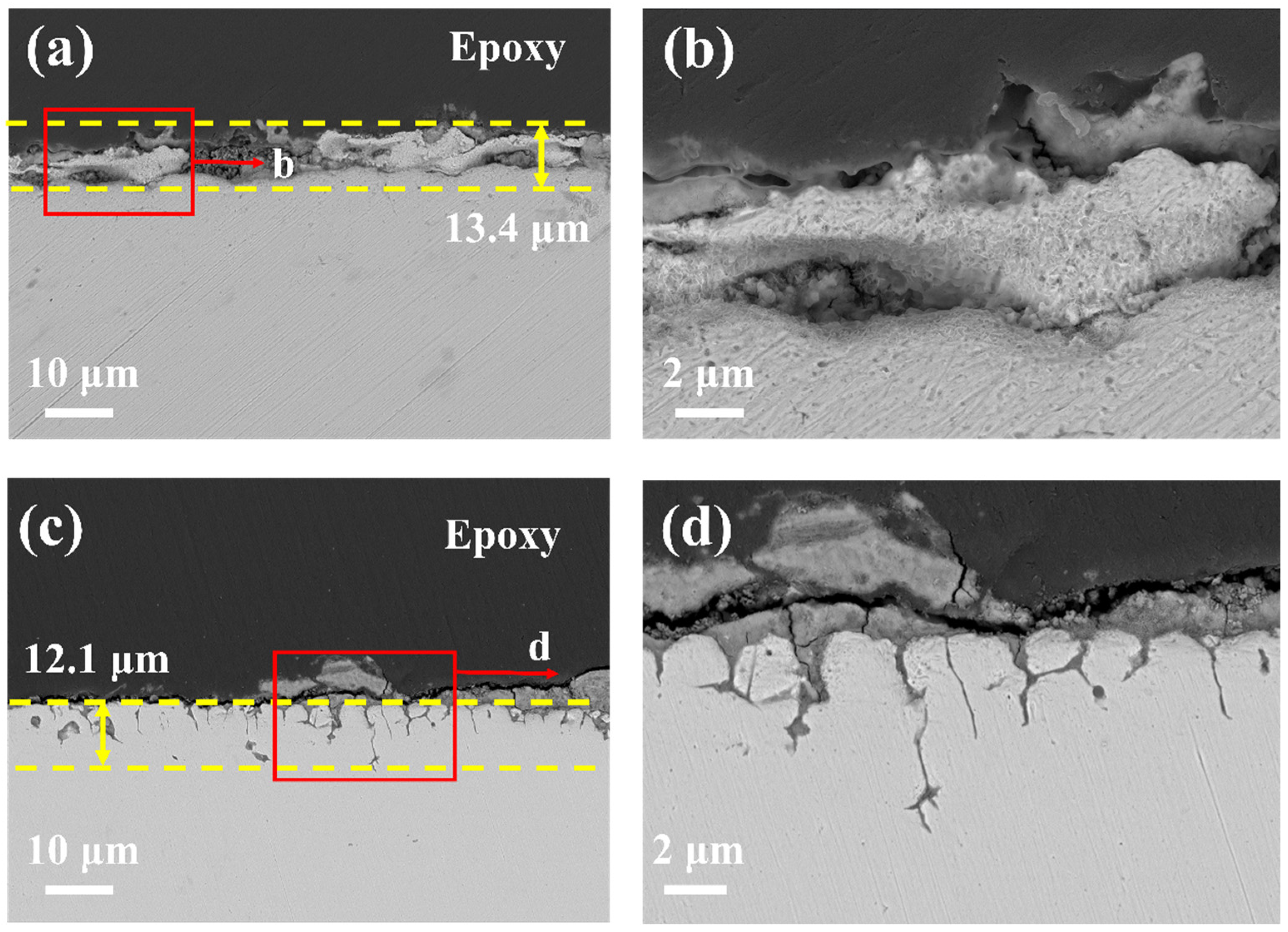
- 20G shows uniform surface corrosion with almost no protective oxide formation on the surface, the corrosion depth reaches 13.4 µm after exposure in molten chloride salt at 700 °C for 50 h.
- (2)
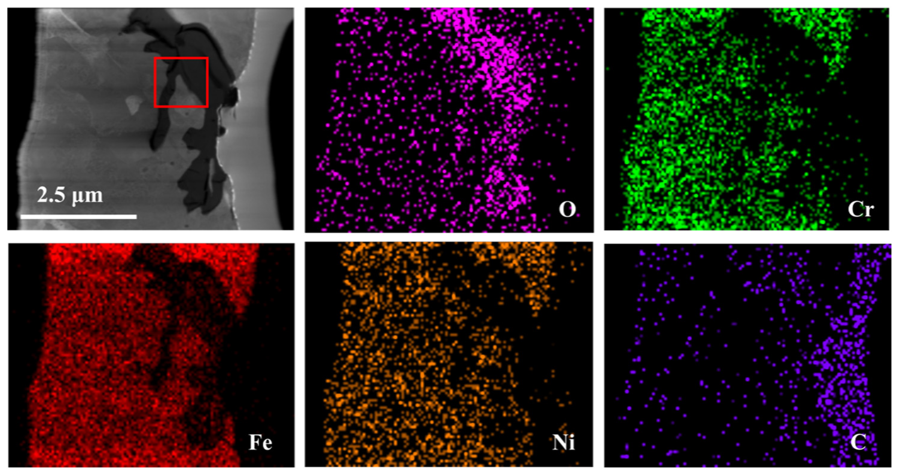
- Unlike 20G, in the case of TP347H austenitic steel, the higher Cr content of TP347H alloy promotes the formation of Cr-containing spinel oxide and provides better corrosion resistance than 20G carbon steel.
- (3)
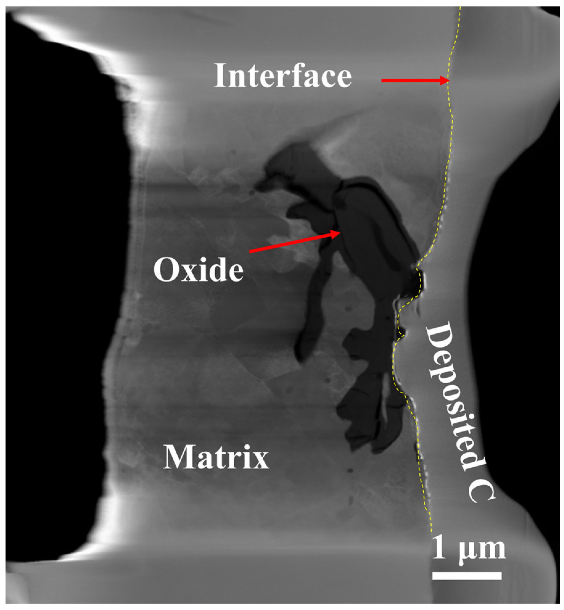
- Due to the highly corrosive nature of molten chloride salts, the Cl− in molten salt could react with oxide, causing the oxide films to crack and become loose and porous, thereby reducing its effective protection for Fe-based alloys.
- (4)
- Due to the higher energy state of the GB, it usually acts as the preferred path of element migration. After the oxide film diminishes their protective ability, the oxygen impurity in the chloride salt can diffuse along the GBs into the TP347H matrix and form (Fe3-x-yCrxNiy)O4 spinel at the GBs, accelerating the oxidation and intergranular corrosion of austenitic steel in molten chloride salts.
Author Contributions
Funding
Data Availability Statement
Conflicts of Interest
References
- Ding, W.; Bonk, A.; Bauer, T. Corrosion behaviors and mitigation strategies of metallic alloys in molten chloride salts for thermal energy storage in CSP plants. In Proceedings of the SOLARPACES 2018: International Conference on Concentrating Solar Power and Chemical Energy System, Daegu, Republic of Korea, 1–4 October 2019. [Google Scholar]
- Gomez-Vidal, J.C.; Tirawat, R. Corrosion of alloys in a chloride molten salt (NaCl-LiCl) for solar thermal technologies. Sol. Energy Mater. Sol. Cells 2016, 157, 234–244. [Google Scholar] [CrossRef]
- Fernández, A.G.; Gomez-Vidal, J.; Oró, E.; Kruizenga, A.; Solé, A.; Cabeza, L.F. Mainstreaming commercial CSP systems: A technology review. Renew. Energy 2019, 140, 152–176. [Google Scholar] [CrossRef]
- Williams, D.F. Assessment of Candidate Molten Salt Coolants for the NGNP/NHI Heat-Transfer Loop; ORNL/TM-2006/69; Oak Ridge National Lab. (ORNL): Oak Ridge, TN, USA, 2006.
- Zheng, G.; Sridharan, K. Corrosion of Structural Alloys in High-Temperature Molten Fluoride Salts for Applications in Molten Salt Reactors. JOM 2018, 70, 1535–1541. [Google Scholar] [CrossRef]
- Simpson, M.F.; Smolik, G.R.; Sharpe, J.P.; Anderl, R.A.; Petti, D.A.; Hatano, Y.; Hara, M.; Oya, Y.; Fukada, S.; Tanaka, S.; et al. Quantitative measurement of beryllium-controlled redox of hydrogen fluoride in molten Flibe. Fusion Eng. Des. 2006, 81, 541–547. [Google Scholar] [CrossRef]
- Zhang, J.; Forsberg, C.W.; Simpson, M.F.; Guo, S.; Lam, S.T.; Scarlat, R.O.; Carotti, F.; Chan, K.J.; Singh, P.M.; Doniger, W.; et al. Redox potential control in molten salt systems for corrosion mitigation. Corros. Sci. 2018, 144, 44–53. [Google Scholar] [CrossRef]
- Zhu, M.; Zeng, S.; Zhang, H.; Li, J.; Cao, B. Electrochemical study on the corrosion behaviors of 316 SS in HITEC molten salt at different temperatures. Sol. Energy Mater. Sol. Cells 2018, 186, 200–207. [Google Scholar] [CrossRef]
- Coscia, K.; Nelle, S.; Elliott, T.; Mohapatra, S.; Oztekin, A.; Neti, S. Thermophysical Properties of LiNO3–NaNO3–KNO3 Mixtures for Use in Concentrated Solar Power. J. Sol. Energy Eng. 2013, 135, 034506. [Google Scholar] [CrossRef]
- Sarvghad, M.; Delkasar Maher, S.; Collard, D.; Tassan, M.; Will, G.; Steinberg, T.A. Materials compatibility for the next generation of Concentrated Solar Power plants. Energy Storage Mater. 2018, 14, 179–198. [Google Scholar] [CrossRef]
- Kurley, J.M.; Halstenberg, P.W.; McAlister, A.; Raiman, S.; Dai, S.; Mayes, R.T. Enabling chloride salts for thermal energy storage: Implications of salt purity. RSC Adv. 2019, 9, 25602–25608. [Google Scholar] [CrossRef]
- Williams, D.F.; Toth, L.M.; Clarno, K. Assessment of Candidate Molten Salt Coolants for the Advanced High Temperature Reactor (AHTR); ORNL/TM-2006/12; Oak Ridge National Lab. (ORNL): Oak Ridge, TN, USA, 2006.
- Raiman, S.S.; Lee, S. Aggregation and data analysis of corrosion studies in molten chloride and fluoride salts. J. Nucl. Mater. 2018, 511, 523–535. [Google Scholar] [CrossRef]
- Patel, N.S.; Pavlik, V.; Boca, M. High-Temperature Corrosion Behavior of Superalloys in Molten Salts—A Review. Crit. Rev. Solid State Mater. Sci. 2017, 42, 83–97. [Google Scholar] [CrossRef]
- Zhang, S.; Li, H.; Jiang, Z.; Zhang, B.; Li, Z.; Wu, J.; Feng, H.; Zhu, H.; Duan, F. Chloride- and sulphate-induced hot corrosion mechanism of super austenitic stainless steel S31254 under dry gas environment. Corros. Sci. 2020, 163, 108295. [Google Scholar] [CrossRef]
- Rippy, K.; Witteman, L.; Taylor, P.R.; Vidal, J.C. Predicting and understanding corrosion in molten chloride salts. MRS Adv. 2023, 8, 855859. [Google Scholar] [CrossRef]
- Sheng, S.M. Research Development of High Temperature Chlorine Corrosion and Protection in Waste Incineration. Guangzhou Chem. Ind. 2021, 49, 17. [Google Scholar]
- Shankar, A.R.; Mudali, U.K. Corrosion of type 316L stainless steel in molten LiCl–KCl salt. Mater. Corros. 2008, 59, 878–882. [Google Scholar] [CrossRef]
- Zahs, A.; Spiegel, M.; Grabke, H.J. Chloridation and oxidation of iron, chromium, nickel and their alloys in chlorizing and oxidizing atmosoheres at 400–700 °C. Corros. Sci. 2000, 42, 1093–1122. [Google Scholar] [CrossRef]
- Singh, H.; Chatha, S.S.; Sidhu, B.S. Ceria-Doped Cr3C2–NiCr Coatings on Austenite Steel for Investigation in Actual Boiler Environment. Arab. J. Sci. Eng. 2022, 48, 3723–3747. [Google Scholar] [CrossRef]
- Liu, S.; Liu, Z.; Wang, Y.; Tang, J. A comparative study on the high temperature corrosion of TP347H stainless steel, C22 alloy and laser-cladding C22 coating in molten chloride salts. Corros. Sci. 2014, 83, 396–408. [Google Scholar] [CrossRef]
- Wei, L.; Wang, S.; Liu, G.; Hao, W.; Liang, K.; Yang, X.; Diao, W. Corrosion Behavior of High-Cr–Ni Materials in Biomass Incineration Atmospheres. ACS Omega 2022, 7, 21546–21553. [Google Scholar] [CrossRef]
- Liu, C.; Little, J.A.; Henderson, P.J.; Ljung, P. Corrosion of TP347H FG stainless steel in a biomass fired PF utility boiler. J. Mater. Sci. 2001, 36, 1015–1026. [Google Scholar] [CrossRef]
- Liu, Z.; Liu, C.; Gao, Y.; Zheng, C. High Temperature Corrosion Behaviors of 20G Steel, Hastelloy C22 Alloy and C22 Laser Coating under Reducing Atmosphere with H2S. Coatings 2020, 10, 617. [Google Scholar] [CrossRef]
- Luo, W.W.; Liu, Z.D.; Wang, Y.T.; Yang, R.-J. High Temperature Corrosion Behaviors of the Superheater Materials. Procedia Eng. 2012, 36, 212–216. [Google Scholar] [CrossRef]
- Shi, C.; Chen, K.; Zhu, X.; Fu, D.; Qi, Y.; Cheng, F.; Li, J. Study on corrosion failure prevention of expanded solid expandable tubular. Eng. Fail. Anal. 2021, 121, 105180. [Google Scholar] [CrossRef]
- Li, Y.S.; Spiegel, M.; Shimada, S. Corrosion behaviour of various model alloys with NaCl–KCl coating. Mater. Chem. Phys. 2005, 93, 217–223. [Google Scholar] [CrossRef]
- Liu, S.; Wu, H.; Zhao, Q.; Liang, Z. Corrosion failure analysis of the heat exchanger in a hot water heating boiler. Eng. Fail. Anal. 2022, 142, 106847. [Google Scholar] [CrossRef]
- He, G.; Zou, Q.; Liao, K.; Leng, J.; Zhao, S. Corrosion mechanism of high temperature and O2 content in steamed CO2/O2/SO2 system and failure behavior of 20G steel on steam-injection pipelines. Process Saf. Environ. 2022, 163, 528–542. [Google Scholar] [CrossRef]
- Liu, X.; Duan, Y.; Zheng, L.; Long, L.; Khalid, Z.; Huang, Q.; Jiang, X. Effect of complex municipal solid waste incineration flue gas on the corrosion of various alloys at 550 °C. Fuel 2024, 355, 129524. [Google Scholar] [CrossRef]
- Li, X.Z.; Li, H.C.; Wang, Y.T.; Li, B. Investigations on the behavior of laser cladding Ni–Cr–Mo alloy coating on TP347H stainless steel tube in HCl rich environment. Surf. Coat. Technol. 2013, 232, 627–639. [Google Scholar] [CrossRef]
- Janz, G.J.; Allen, C.B.; Bansal, N.P.; Murphy, R.M.; Tomkins, R.P. Physical Properties Data Compilations Relevant to Energy Storage; U.S. Department of Commerce: Washington, DC, USA, 1978.
- Sihm, A.L. Melting Points of Binary and Ternary Eutectic Chloride Salts MD Simulations on LiCl-NaCl-KCl and Its Binary Constituents. Master’s Thesis, UPPSALA University, Uppsala, Sweden, 2019. [Google Scholar]
- Shi, H.; Wu, T.; Gong, Q.; Ding, W.; Chai, Y.; Weisenburger, A.; Chang, L.; Zhang, Z.; Wang, K.; Richter, J.; et al. Hot corrosion behavior of additively manufactured stainless steel 316L and Inconel 718 in MgCl2/KCl/NaCl chloride salts at 700 °C. Corros. Sci. 2022, 207, 110561. [Google Scholar] [CrossRef]
- Qiu, J.; Macdonald, D.D.; Schoell, R.; Han, J.; Mastromarino, S.; Scully, J.R.; Kaoumi, D.; Hosemann, P. Electrochemical study of the dissolution of oxide films grown on 316L stainless steel in molten fluoride salt. Corros. Sci. 2021, 186, 109457. [Google Scholar] [CrossRef]
- Pickering, H.; Beck, F.; Fontana, M. Rapid intergranular oxidation of 18–8 stainless steel by oxygen and dry sodium chloride at elevated temperatures. Trans. Am. Soc. Met. 1961, 53, 793–803. [Google Scholar]
- Cho, S.H.; Zhang, J.S.; Shin, Y.J.; Park, S.W.; Park, H.S. Corrosion behavior of Fe–Ni–Cr alloys in the molten salt of LiCl–Li2O at high temperature. J. Nucl. Mater 2004, 325, 13–17. [Google Scholar] [CrossRef]
- Sun, H.; Wang, J.; Li, Z.; Zhang, P.; Su, X. Corrosion behavior of 316SS and Ni-based alloys in a ternary NaCl-KCl-MgCl2 molten salt. Solar Energy. Sol. Energy 2018, 171, 320–329. [Google Scholar] [CrossRef]
- Li, Y.S.; Niu, Y.; Wu, W.T. Accelerated corrosion of pure Fe, Ni, Cr and several Fe-based alloys induced by ZnCl2–KCl at 450 °C in oxidizing environment. Mater. Sci. Eng. A 2003, 345, 64–71. [Google Scholar] [CrossRef]
- Ding, W.; Bonk, A.; Gussone, J.; Bauer, T. Cyclic voltammetry for monitoring corrosive impurities in molten chlorides for thermal energy storage. Energy Procedia 2017, 135, 82–91. [Google Scholar] [CrossRef]
- Bischoff, J.; Motta, A.T. Oxidation behavior of ferritic–martensitic and ODS steels in supercritical water. J. Nucl. Mater. 2012, 424, 261–276. [Google Scholar] [CrossRef]


| C | Si | Mn | S | P | Cr | Ni | Other | |
|---|---|---|---|---|---|---|---|---|
| 20G | 0.19 | 0.20 | 0.35 | 0.014 | 0.012 | 0.10 | 0.04 | Mo:0.08 |
| TP347H | 0.04~0.1 | ≤0.75 | ≤2.00 | ≤0.03 | ≤0.035 | 18~20 | 10~13 | Nb:0.8 |
| Position | O | Cr | Fe | Ni | C |
|---|---|---|---|---|---|
| 1 | 32.6 | 13.8 | 37.9 | 10.8 | 4.9 |
| 2 | 0.5 | 10.9 | 69.1 | 14.8 | 4.7 |
Disclaimer/Publisher’s Note: The statements, opinions and data contained in all publications are solely those of the individual author(s) and contributor(s) and not of MDPI and/or the editor(s). MDPI and/or the editor(s) disclaim responsibility for any injury to people or property resulting from any ideas, methods, instructions or products referred to in the content. |
© 2024 by the authors. Licensee MDPI, Basel, Switzerland. This article is an open access article distributed under the terms and conditions of the Creative Commons Attribution (CC BY) license (https://creativecommons.org/licenses/by/4.0/).
Share and Cite
Xie, S.; Lei, M.; Sun, J.; Yang, C.; Liu, W.; Yun, D.; Zhao, X.; Qiu, J. Corrosion Behavior of 20G and TP347H in Molten LiCl-NaCl-KCl Salt. Nanomaterials 2024, 14, 1026. https://doi.org/10.3390/nano14121026
Xie S, Lei M, Sun J, Yang C, Liu W, Yun D, Zhao X, Qiu J. Corrosion Behavior of 20G and TP347H in Molten LiCl-NaCl-KCl Salt. Nanomaterials. 2024; 14(12):1026. https://doi.org/10.3390/nano14121026
Chicago/Turabian StyleXie, Shijing, Min Lei, Jiawei Sun, Chongdou Yang, Wenbo Liu, Di Yun, Xiqiang Zhao, and Jie Qiu. 2024. "Corrosion Behavior of 20G and TP347H in Molten LiCl-NaCl-KCl Salt" Nanomaterials 14, no. 12: 1026. https://doi.org/10.3390/nano14121026