Article

SnO2-Based Interfacial Engineering towards Improved Perovskite Solar Cells

Guangdong Provincial Key Laboratory of Information Photonics Technology, School of Physics and Opto-Electronic Engineering, Guangdong University of Technology, Guangzhou 510006, China
*
Author to whom correspondence should be addressed.
Nanomaterials 2024, 14(17), 1406; https://doi.org/10.3390/nano14171406
Submission received: 11 August 2024 / Revised: 24 August 2024 / Accepted: 27 August 2024 / Published: 28 August 2024

Abstract

:
Interfacial engineering is of great concern in photovoltaic devices. Metal halide perovskite solar cells (PSCs) have garnered much attention due to their impressive development in power conversion efficiencies (PCEs). Benefiting from high electron mobility and good energy-level alignment with perovskite, aqueous SnO2 as an electron transport layer has been widely used in n-i-p perovskite solar cells. However, the interfacial engineering of an aqueous SnO2 layer on PSCs is still an obscure and confusing process. Herein, we proposed the preparation of n-i-p perovskite solar cells with different concentrations of SnO2 as electron transport layers and achieved optimized PCE with an efficiency of 20.27%. I Interfacial engineering with regard to the SnO2 layer is investigated by observing the surface morphology, space charge-limited current (SCLC) with the use of an electron-only device, and time-resolved photoluminescence (TRPL) of perovskite films.

1. Introduction

Named after mineral calcium titanate (CaTiO3), metal halide perovskite originally possessed the same crystal structure as that of the former, with the chemical formula ABX3. The A-site cation is coordinated to 12 X anions, forming a cuboctahedron, while the six-fold-coordinated B-site cation has an octahedral geometry [1,2,3]. Metal halide perovskite-based solar cells have garnered much attention worldwide due to the rapid progress they have facilitated in power conversion efficiency (PCE), and they have become a potentially strong competitor in the photovoltaic performance race [4,5,6]. Moreover, PSCs exhibit great promise in large-scale production and mainstream technology, owing to their low-cost, scalable, and simple solution processing techniques [7,8,9]. Despite the tremendous breakthroughs and rapid progress in the photovoltaic performance of perovskite solar cells, from 9.7% with pure MAPbI3 in 2012 to 26%, the remaining issues in interfacial engineering that urgently need to be resolved constitute a multifaceted challenge [10,11,12].
The n-i-p PSC configuration is regarded as a normal device structure; the active perovskite layer is directly spin-coated on an n-type electron transport layer (ETL), such as SnO2. The crystalline quality of the perovskite and the morphology of the buried interface are directly affected by the surface chemistry of the ETL [13,14,15]. Therefore, research on ETL has become one of the most relevant scientific subjects in the development of highly efficient and stable n-i-p PSCs. For instance, Yan et al. reported low-temperature solution-processed nanocrystalline SnO2 as an excellent alternative ETL and demonstrated PSCs with an average efficiency of 16.02% [16]. Kim et al. studied the band alignment between La-doped BaSnO3 (LBSO) and MAPbI3 perovskite, demonstrating LBSO as the next-generation ETL, with its high mobility, photostability and structural stability [17]. Pang and co-workers designed a Cl-containing tin-based ETL, SnOx-Cl, to realized a spontaneous ion exchange reaction at the interface of SnOx–Cl/MAPbI3, producing PSCs with an efficiency of 20.32% [18]. Chlorine-capped TiO2 colloidal nanocrystals were applied in a PSC to mitigate interfacial recombination and improve interface binding [19].
Aqueous SnO2 has been widely employed in n-i-p perovskite solar cells due to its high electron mobility and good energy-level alignment with perovskite and electrodes [20,21,22,23,24]. A SnO2 ETL can be obtained via the thermal oxidation of Sn(iv) isoprenoids, SnO2 quantum dots, and ALD (atomic layer deposition) [25,26,27,28]. Theories on the formation and properties of crystalline interfaces have been developed [29,30]. An optimized SnO2 electron transport layer showed great advantages, in terms of reduced interfacial recombination losses, controlled energy levels, and increased charge transport. SnO2 purchased directly from the market requires concentration dilution before application in PSCs, but the optimization of SnO2 concentrations is rarely reported. Moreover, researchers usually determine dilute SnO2 concentration ratios experientially. For example, Yang and co-workers reported a SnO2 precursor diluted in isopropanol and deionized water in a ratio of 1:3:2.5, achieving the same PCE as that of flexible PSC, reaching up to 18.71% [31]. Zhou et al. employed a 15 wt.% SnO2 aqueous solution in H2O as an ETL and realized a PCE of 21.92% [32]. However, those reports reached no consensus on the optimal SnO2 dilution ratio. At the same time, fundamental knowledge is lacking for a thorough understanding of the key role of different concentrations of SnO2 in crystallisation kinetics. Therefore, it is necessary to further explore the effects of concentrations of SnO2 as an ETL on device performance.
Here, we propose a simple and effective strategy to adjust the concentration of SnO2 and preliminarily validate the optimal dilution ratio of SnO2 in water. In this work, the efficiency of the device prepared by using the optimal concentration ratio (SnO2 2.4%) reached 20.27%. This work provides a comprehensive understanding of SnO2 concentrations and of how to realize efficient perovskite photovoltaic devices with optimized SnO2 layers.

2. Experimental Section

Materials. All chemicals and materials were purchased from Aladin and directly used in the reactions and depositions without further purification. SnO2 hydrocolloidal dispersion solution (SnO2, 99.99%), leaching iodide (PbI2, 99.99%), lead bromide (PbBr2, 99.99%), formamidine hydroiodide (FAI, 99.99%), formamidine bromide (FABr, 99.99%), cesium iodide (CsI, 99.99%), methylammonium iodide (MAI, 99.99%), methylammonium chloride (MACl, 99.99%), n, n-dimethylformamide (DMF, 99.99%), dimethyl sulfoxide (DMSO, 99.99%), ethyl acetate (EA, 99.99%), Spiro-OMeTAD (99.99%), LiTFSi (99.99%), and 4-tert-butylpyridine (tBP, 99.99%) were used.
Device Fabrication. The FTO substrate was pre-washed with pure water, acetone, and isopropanol in an ultrasound bath for 15 min, followed by undergoing UV zone treatment for 20 min. We prepared four kinds of perovskite solar cell devices with different concentrations of SnO2. SnO2 was spin-coated at a speed of 3000 r/30 s, followed by undergoing annealing at 200 °C for 40 min. The perovskite film was deposited onto an electron transport layer, followed by the preparation of a hole transport layer (HTL) and a Ag metal electrode. Finally, devices with a structure of FTO/ETL/Perovskite/HTL/Ag were fabricated.
Measurement. The current density–voltage (J–V) characteristics of the perovskite solar cells were measured using an integrated solar simulator (JIS C 8942 Class MA). Solar cell performance was characterized under illumination using a standard amorphous Si photodetector (BS 520 S/N 007, Bunko Keiki, Tokyo, Japan), an air mass 1.5 global (AM 1.5 G) solar simulator with an irradiation intensity of 100 mw/cm2. Furthermore, 0.1 cm2 size apertures made of thin metal were attached to each cell before measurement. Scanning electron microscopy (SEM) was performed using JSM-7800F to analyze the surface morphology of the perovskite thin films.

3. Results and Discussion

A plane structure diagram of an n-i-p perovskite solar cell composed of FTO/ETL/Perovskite/Spiro-OMeTAD/Ag is shown in Figure 1, and the detailed fabrication process is displayed accordingly. It is obvious that the n-i-p perovskite solar cell consists of the conductive substrate FTO, a SnO2 electron transport layer, a perovskite active layer, a Spiro-OMeTAD hole transport layer, and a conductive metal electrode made of Ag. The SnO2 ETL was employed to transport electrons that were generated in the active perovskite to the circuit. Therefore, systematic studies of SnO2 electron transport layers are of critical importance for the development of perovskite solar cells.
In this work, the original aqueous SnO2 (12%) purchased from the aforementioned company was employed after further processing. In detail, the original SnO2 was in the form of nanoparticles, which were subjected to dilution with water, forming SnO2 concentrations of 4%, 3%, 2.4%, and 2%. The SnO2 solutions with varying degrees of dilution showed varied surface characteristics, directly affecting perovskite crystallization. Based on this, the surface morphology evolution and conductivity of the perovskite layer deposited on SnO2 thin films with different concentrations and the performance variation of the PSCs based on different SnO2 concentrations were studied. Interfacial engineering based on SnO2 ETLs was discussed systematically, and this is expected to provide in-depth understanding of ETL dynamics and give guidance on enhanced PSC performance.
The SnO2 hydrocolloidal dispersion solution purchased from the aforementioned company generally exists as a SnO2 quantum dot aqueous solution, with an original concentration of 12%. The original SnO2 solution may emerge in a cluster state; thus, further dilution of the original solution is necessary. Bonding issues are very important factors determining the quality of deposited perovskite films. As shown in Figure 2, through scanning electron microscopy (SEM), the morphological evolution of the perovskite films deposited on the different SnO2 concentrations is evident. When the SnO2 concentration was 4%, the grain size of the perovskite film deposited on it was small, with the average grain size being about 340 nm. As the SnO2 concentration was decreased to 3%, the grain size of perovskite films increased to 401 nm; the grain size further increased to 439 nm as the concentration was decreased to 2.4%. At this point, the perovskite layer showed a more compact grain boundary and a smooth surface topography, indicating that SnO2 at this concentration is more suitable as an ETL for PSC device fabrication. The further dilution (2% SnO2) resulted in a rough surface and inferior perovskite deposition. The surface morphologies of different SnO2 ETLs were compared, and the differences were not obvious (Supporting Information Figure S1).
We further investigated the steady-state photoluminescence (PL) spectra and time-resolved photoluminescence (TRPL) of perovskite films grown on different concentrations of SnO2. The quenched luminous intensity suggested that the electron transport layer had an enhanced capacity to extract and collect charge carriers generated by the perovskite layer. When the concentration of SnO2 was 4%, the highest PL intensity indicated carrier accumulation and aggregation in the perovskite film. This also implied that the perovskite layer was not conducive to good carrier transport performance, as confirmed by the conductivity analysis in Figure 3b. As SnO2 concentration decreased (3%), the carrier transportation that occurred in the electron transport layer was improved, and the conductivity of the perovskite layer was correspondingly enhanced. As the SnO2 was diluted to 2%, the carriers produced by the perovskite film became more favorably absorbed by the electron transport layer, resulting in the lowest corresponding luminous spectral intensity. The quenching efficiencies of PL emission at the interface between the perovskite and ETL were in the order of 2.4% > 3% > 2% > 4%, which indicated more effective electron extraction from the perovskite/diluted SnO2 (2.4%).
According to the formula for conductivity (conductivity = current/voltage = 1/resistance), it is evident that a steeper slope corresponds to higher conductivity and lower resistance in the electron transport layer, indicating improved carrier transport efficiency. When the SnO2 concentration is 4%, it can be clearly seen that the slope is the lowest, and the value is about 0.13, which indicates that the large resistance generated by SnO2 hinders carrier transport. With a decreased SnO2 concentration, the perovskite conductivity is obviously increased. When the SnO2 concentration is 2.4%, the resulting perovskite film exhibits the highest electrical conductivity (approximately 0.23), confirming minimal resistance and enhanced charge carrier absorption from the perovskite layer. The electron-transport properties of diluted SnO2 layers were evaluated using the space charge-limited current (SCLC) measurement taken with the electron-only device, as indicated in Figure 3d. The evaluated trap-filled limit voltages (VTFLs) of diluted SnO2 with the original, 4%, 3% and 2.4% concentrations are 0.18, 0.1, 0.08 and 0.14 V, respectively. The lower VTFL for SnO2 of 2.4% indicates a lower trap density.
To more accurately quantify the impact of the SnO2 layer, the detailed distribution of the performance parameters extracted from more cells is shown in Figure 4. In detail, when the SnO2 concentration was 4%, the device exhibited an average PCE of only 17.40%, a Voc of 1.02 V, an FF of 73.26%, and a JSC of 23.29 mA/cm2. This can be attributed to the thick SnO2 thin film and its inferior perovskite conductivity. When the concentration increased to 3% and 2.4%, the device performance became gradually enhanced. In particular, for the device with an SnO2 concentration of 2.4%, it showed the highest average PCE of 20.27%. The further addition of water in SnO2 solution (2%) resulted in the inferior performance of device, with an average PCE of only 18.28%. To investigate the effect of different concentrations of SnO2 on the performance of perovskite solar cells, the activities of different perovskite solar cells are summarized in Table 1.
The corresponding external efficiency (EQE) spectra and integrated current density (integrated Jsc) values of different devices were recorded; the results indicated that the integrated Jsc values were in accordance with the Jsc values from the J–V curves (Supporting Information Figure S2). The enhanced photovoltaic performance can be ascribed to the following factors: (1) dense and uniform coverage of the SnO2 layer on the substrate; (2) the smooth interface and controlled defects originating from uniformly dispersed SnO2 colloids in the aqueous solution; and (3) improved perovskite crystallinity and conductivity.

4. Conclusions

In summary, aqueous SnO2 solutions with different concentrations were employed in perovskite solar cells. Decreased concentrations facilitated perovskite crystallinity and conductivity, and improved the performance of the devices. The PSC with 2.4% SnO2 showed an efficiency of 20.27%. However, the further dilution of SnO2 with a 2% concentration resulted in reduced performance. A moderate SnO2 concentration is conducive to dense and uniform coverage, conductivity, and the electron transport of the perovskite layer. An appropriate SnO2 concentration is essential for efficient perovskite solar cells.

Supplementary Materials

The following supporting information can be download at: https://www.mdpi.com/article/10.3390/nano14171406/s1, Figure S1: Surface morphologies of different SnO2 with varied concentration; Figure S2: The EQE spectra and integrated current of different devices.

Author Contributions

Investigation, B.L, C.L. and X.Z.; resources, B.L. and C.L.; writing—original draft preparation, B.L.; writing—review and editing, X.Z.; supervision, X.Z.; funding acquisition, X.Z. All authors have read and agreed to the published version of the manuscript.

Funding

This research was funded by Natural Science Foundation of Guangdong Province, grant number 2023A1515011467, and Natural Science Foundation of Guangdong Province, grant number 2023A1515011467.

Data Availability Statement

The data that support the findings of this study are available within the article.

Conflicts of Interest

The authors declare no conflict of interest.

References

  1. Chin, Y.C.; Daboczi, M.; Henderson, C.; Luke, J.; Kim, J.S. Suppressing PEDOT: PSS Doping-Induced Interfacial Recombination Loss in Perovskite Solar Cells. ACS Energy Lett. 2022, 7, 560–568. [Google Scholar] [CrossRef]
  2. Wang, A. Research on High-Efficiency and High-Stability Tin-Based Perovskite Solar Cells Fabricated Based on Blade-Coating. 2023. Available online: https://kns.cnki.net/kcms2/article/abstract?v=xpM8-w1VMS-KGm44RzbUD-k5gKqcTB80Zyr2mgKzw9se9Q9Uyqkx-t6P63CbQ8m5uZgBk1f6dVRQAtMp7wRcc7oGwW1ZKYhwy8MNhtdWO3x0gkzDM-6AUkwGmfeyRh0kAAtgEgtgoI6bI_lMChjSGSFYl6crD8PKyPg78ksf-gSfliKPow3iqC8D4uXTs6KjsWmJfJaiReanNn27T6Nt_46D66_rlaAJf6CdDX62athk2mYqK-gFZwS_siRgjQFYcT7h1uHiQ56ct4MYdJP6xOVfN7u76tzLogABdu373xo4sY_kIAtb5A==&uniplatform=NZKPT&language=CHS (accessed on 26 August 2024).
  3. You, S.; Eickemeyer, F.T.; Gao, J.; Yum, J.-H.; Zheng, X.; Ren, D.; Xia, M.; Guo, R.; Rong, Y.; Zakeeruddin, S.M.; et al. Bifunctional hole-shuttle molecule for improved interfacial energy level alignment and defect passivation in perovskite solar cells. Nat. Energy 2023, 8, 515–525. [Google Scholar] [CrossRef]
  4. Ru, P.; Bi, E.; Zhang, Y.; Wang, Y.; Kong, W.; Sha, Y.; Tang, W.; Zhang, P.; Wu, Y.; Chen, W.; et al. High Electron Affinity Enables Fast Hole Extraction for Efficient Flexible Inverted Perovskite Solar Cells. Adv. Energy Mater. 2020, 10, 1903487. [Google Scholar] [CrossRef]
  5. Du, J. Study on Interfacial Passivation of Methylamine Lead Iodide Perovskite Solar Cells. 2022. Available online: https://kns.cnki.net/kcms2/article/abstract?v=xpM8-w1VMS_QrOqtMKf5yZQvTDNBAQ1INRdidICYN33XL5otgsV87ZXaBvlKWrJAzYZABIBc0LeFtV1Us5eYPKGqIc2ow2NtzQptt9K_CPC1aonQkbu5XqvWS5uGVpBBfxMsdYwM5AWZ4BBMEcGuGRTxf4SPIYRcrf6X_SDs8U3tJpcqD1Y5yII12-Q91cZh5uNEa0QY-WCcl1w0puBI4c7puNa7bIQ9ogPl1rEbek_YiBTlI5I12IahQE6l7qEZCTYCE6p1fIWirzcTDqPkBFCgeLcD0laH5dIZZT8rLGuqX492u85qkw==&uniplatform=NZKPT&language=CHS (accessed on 26 August 2024).
  6. Lan, Z.; Huang, H.; Du, S.; Lu, Y.; Sun, C.; Yang, Y.; Zhang, Q.; Suo, Y.; Qu, S.; Wang, M.; et al. Cascade Reaction in Organic Hole Transport Layer Enables Efficient Perovskite Solar Cells. Angew. Chem. Int. Ed. 2024, 63, e202402840. [Google Scholar] [CrossRef] [PubMed]
  7. Wang, S.; Sina, M.; Parikh, P.; Uekert, T.; Shahbazian, B.; Devaraj, A.; Meng, Y.S. Role of 4-tert-Butylpyridine as a Hole Transport Layer Morphological Controller in Perovskite Solar Cells. Nano Lett. 2016, 16, 5594–5600. [Google Scholar] [CrossRef]
  8. Wu, T.; Zhuang, R.; Zhao, R.; Zhao, R.; Zhu, L.; Liu, G.; Wang, R.; Zhao, K.; Hua, Y. Understanding the Effects of Fluorine Substitution in Lithium Salt on Photovoltaic Properties and Stability of Perovskite Solar Cells. ACS Energy Lett. 2021, 6, 2218–2228. [Google Scholar] [CrossRef]
  9. Meng, X. Research on Interface and Stability of Perovskite Solar Cells. 2022. Available online: https://kns.cnki.net/kcms2/article/abstract?v=xpM8-w1VMS_-INBGTNPdh24wC-k4UiIhshRdRYr50iAMp8AnW6TVoQJMGlF4Cw2VxAme7pPj1sit-6VGtJtrHu3DhSXEhyuf_4BmWjpHGrR1B038794Hb2SMcYjoGqCE2fqFmus9Mh73Ab3DMeCOfAhJB10p39AyuGIY2BwRJD5qIDL7YuSdpw3XK5KlqycU5FOVW0Vuo1w0KCFheGOQ40Q_SfyS3F7OqtelGJTWKcVHegBqg6ZKu8sBO1BhqxmMmC8sUHH-djvobHu0wXlPDH4THBPwczB8G0xSwfWl9LHoaaE2e5A7tw==&uniplatform=NZKPT&language=CHS (accessed on 26 August 2024).
  10. Yu, S.; Xiong, Z.; Zhou, H.; Zhang, Q.; Wang, Z.; Ma, F.; Qu, Z.; Zhao, Y.; Chu, X.; Zhang, X.; et al. Homogenized NiOx nanoparticles for improved hole transport in inverted perovskite solar cells. Science 2023, 382, 1399–1404. [Google Scholar] [CrossRef]
  11. Kim, J.I.Y.; Lee, J.-W.; Jung, H.S.; Shin, H.; Park, N.-G. High-Efficiency Perovskite Solar Cells. Chem. Rev. 2020, 120, 7867–7918. [Google Scholar] [CrossRef]
  12. Nath, B.; Behera, S.K.; Kumar, J.; Hemmerle, A.; Fontaine, P.; Ramamurthy, P.C.; Mahapatra, D.R.; Hegde, G. Understanding the Heterointerfaces in Perovskite Solar Cells via Hole Selective Layer Surface Functionalization. Adv. Mater. 2024, 36, 2307547. [Google Scholar] [CrossRef]
  13. Cho, K.T.; Paek, S.; Grancini, G.; Roldán-Carmona, C.; Gao, P.; Lee, Y.; Nazeeruddin, M.K. Highly efficient perovskite solar cells with a compositionally engineered perovskite/hole transporting material interface. Energy Environ. Sci. 2017, 10, 621. [Google Scholar] [CrossRef]
  14. Zhu, M.; Duan, Y.; Liu, N.; Li, H.; Li, J.; Du, P.; Tan, Z.; Niu, G.; Gao, L.; Huang, Y.; et al. Electrohydro dynamically Printed High-Resolution Full-Color Hybrid Perovskites. Adv. Funct. Mater. 2019, 29, 1903294. [Google Scholar] [CrossRef]
  15. Yoon, H.; Kang, S.M.; Lee, J.K.; Choi, M. Hysteresis-free low-temperature-processed planar perovskite solar cells with 19.1% efficiency. Energy Environ. Sci. 2016, 9, 2262. [Google Scholar] [CrossRef]
  16. Ke, W.; Fang, G.; Liu, Q.; Xiong, L.; Qin, P.; Tao, H.; Wang, J.; Lei, H.; Li, B.; Wan, J.; et al. Low-Temperature Solution-Processed Tin Oxide as an Alternative Electron Transporting Layer for Efficient Perovskite Solar Cells. J. Am. Chem. Soc. 2015, 137, 6730–6733. [Google Scholar] [CrossRef] [PubMed]
  17. Myung, C.W.; Lee, G.; Kim, K.S. La-doped BaSnO3 electron transport layer for perovskite solar cells. J. Mater. Chem. A 2018, 6, 23071. [Google Scholar] [CrossRef]
  18. Li, Z.; Wang, L.; Liu, R.; Fan, Y.; Meng, H.; Shao, Z.; Cui, G.; Pang, S. Spontaneous Interface Ion Exchange: Passivating Surface Defects of Perovskite Solar Cells with Enhanced Photovoltage. Adv. Energy Mater. 2019, 9, 1902142. [Google Scholar] [CrossRef]
  19. Tan, H.; Jain, A.; Voznyy, O.; Lan, X.; García de Arquer, F.P.; Fan, J.Z.; Quintero-Bermudez, R.; Yuan, M.; Zhang, B.; Zhao, Y.; et al. Efficient and stable solution-processed planar perovskite solar cells via contact passivation. Science 2017, 355, 722–726. [Google Scholar] [CrossRef]
  20. Han, J.; Kwon, H.; Kim, E.; Kim, D.W.; Son, H.J.; Kim, D.H. Interfacial engineering of a ZnO electron transporting layer using self-assembled monolayers for high performance and stable perovskite solar cells. J. Mater. Chem. A 2020, 8, 2105. [Google Scholar] [CrossRef]
  21. Dou, J.; Zhang, Y.; Wang, Q.; Abate, A.; Li, Y.; Wei, M. Highly efficient Zn2SnO4 perovskite solar cells through band alignment engineering. Chem. Commun. 2019, 55, 14673. [Google Scholar] [CrossRef]
  22. Jiang, Q.; Zhang, L.; Wang, H.; Yang, X.; Meng, J.; Liu, H.; Yin, Z.; Wu, J.; Zhang, X.; You, J. Enhanced electron extraction using SnO2 for high-efficiency planar-structure HC(NH2)2PbI3-based perovskite solar cells. Nat. Energy 2017, 2, 16177. [Google Scholar] [CrossRef]
  23. Luan, Y.; Yi, X.; Mao, P.; Wei, Y.; Zhuang, J.; Chen, N.; Lin, T.; Li, C.; Wang, J. High-Performance Planar Perovskite Solar Cells with Negligible Hysteresis Using 2,2,2-Trifluoroethanol-Incorporated SnO2. Science 2019, 28, 433–441. [Google Scholar] [CrossRef]
  24. Jiang, Q.; Zhang, X.; You, J. SnO2: A Wonderful Electron Transport Layer for Perovskite Solar Cells. Small 2018, 14, 1801154. [Google Scholar] [CrossRef]
  25. Jeong, S.; Seo, S.; Park, H.; Shin, H. Atomic layer deposition of a SnO2 electron-transporting layer for planar perovskite solar cells with a power conversion efficiency of 18.3%. Chem. Commun. 2019, 55, 2433–2436. [Google Scholar] [CrossRef]
  26. Yoo, J.J.; Seo, G.; Chua, M.R.; Park, T.G.; Lu, Y.; Rotermund, F.; Kim, Y.-K.; Moon, C.S.; Jeon, N.J.; Correa-Baena, J.-P.; et al. Efficient perovskite solar cells via improved carrier management. Nature 2021, 590, 587–593. [Google Scholar] [CrossRef]
  27. Jung, K.H.; Seo, J.Y.; Lee, S.; Shin, H.; Park, N.G. Solution-processed SnO2 thin film for a hysteresis-free planar perovskite solar cell with a power conversion efficiency of 19.2%. J. Mater. Chem. A 2017, 5, 24790–24803. [Google Scholar] [CrossRef]
  28. Jeong, J.; Kim, M.; Seo, J.; Lu, H.; Ahlawat, P.; Mishra, A.; Yang, Y.; Hope, M.A.; Eickemeyer, F.T.; Kim, M.; et al. Pseudo-halide anion engineering for α-FAPbI3 perovskite solar cells. Nature 2021, 592, 381–385. [Google Scholar] [CrossRef]
  29. Kaur, H.; Siwal, S.S.; Saini, R.V.; Singh, N.; Thakur, V.K. Significance of an Electrochemical Sensor and Nanocomposites: Toward the Electrocatalytic Detection of Neurotransmitters and Their Importance within the Physiological System. ACS Nanosci. Au 2023, 3, 1–27. [Google Scholar] [CrossRef] [PubMed]
  30. Filho, M.A.M.; Farmer, W.; Hsiao, C.L.; dos Santos, R.B.; Hultman, L.; Birch, J.; Ankit, K.; Gueorguiev, G.K. Density Functional Theory-Fed Phase Field Model for Semiconductor Nanostructures: The Case of Self-Induced Core−Shell InAlN Nanorods. Cryst. Growth Des. 2024, 24, 4717–4727. [Google Scholar] [CrossRef] [PubMed]
  31. Yang, D.; Yang, R.; Zhang, C.; Ye, T.; Wang, K.; Hou, Y.; Zheng, L.; Priya, S.; Liu, S. Highest-Efficiency Flexible Perovskite Solar Module by Interface Engineering for Efficient Charge Transfer. Adv. Mater. 2023, 35, 2302484. [Google Scholar] [CrossRef]
  32. Lou, Q.; Lou, G.; Guo, H.; Sun, T.; Wang, C.; Chai, G.; Chen, X.; Yang, G.; Guo, Y.; Zhou, H. Enhanced Efficiency and Stability of n-i-p Perovskite Solar Cells by Incorporation of Fluorinated Graphene in the Spiro-OMeTAD Hole Transport Layer. Adv. Energy Mater. 2022, 12, 2201344. [Google Scholar] [CrossRef]
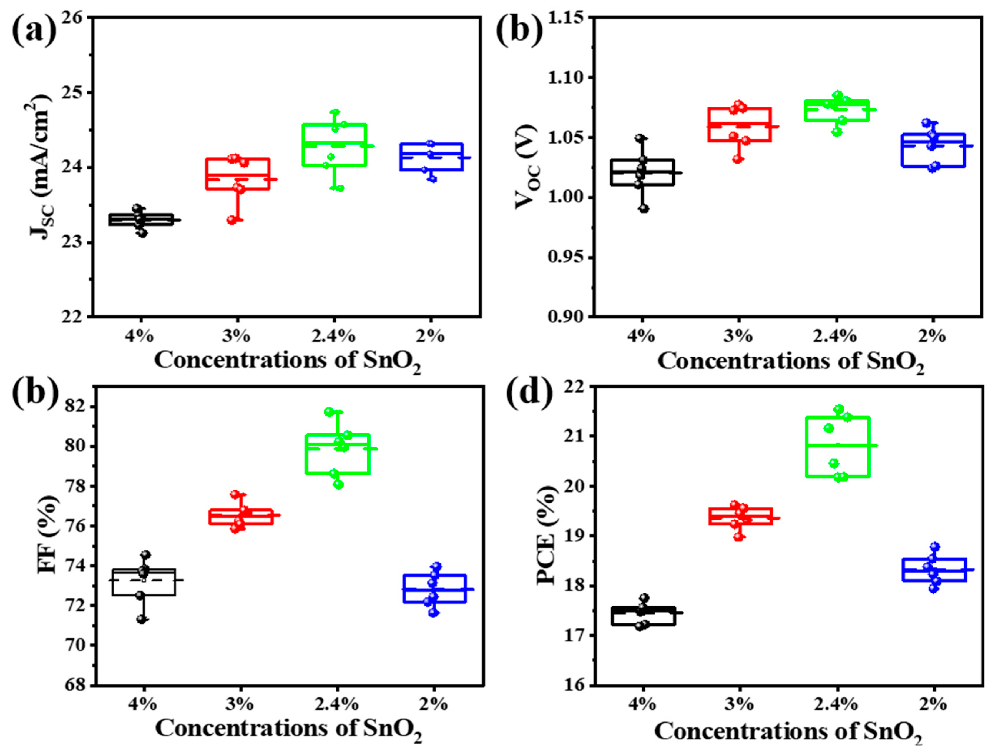
Figure 1. Schematic illustration of device fabrication process.
Nanomaterials 14 01406 g001
Figure 2. SEM images of perovskite and particle dimension distribution. (a) SnO2 4%, (b) SnO2 3%, (c) SnO2 2.4%, and (d) SnO2 2%.
Nanomaterials 14 01406 g002
Figure 3. (a) PL comparison, (b) TRPL, (c) conductivity of perovskite films deposited on different SnO2 layers and (d) SCLC measurement.
Nanomaterials 14 01406 g003
Figure 4. Statistical distribution of the photovoltaic parameters for different PSCs with varied SnO2 concentrations. Distribution of (a) Jsc, (b) Voc, (c) FF, and (d) PCE.
Nanomaterials 14 01406 g004
Table 1. The performance of perovskite solar cells with different SnO2 concentrations.
Concentration RatiosPCE (%)VOC (V)FF (%)JSC (mA/cm2)
SnO2 (4%)17.401.0273.2623.29
SnO2 (3%)19.341.0676.5423.84
SnO2 (2.4%)20.271.0779.924.29
SnO2 (2%)18.281.0472.8224.14
Disclaimer/Publisher’s Note: The statements, opinions and data contained in all publications are solely those of the individual author(s) and contributor(s) and not of MDPI and/or the editor(s). MDPI and/or the editor(s) disclaim responsibility for any injury to people or property resulting from any ideas, methods, instructions or products referred to in the content.

