Abstract
We proposed a novel fiber Mach–Zehnder interferometer (FMZI) that can perform an ultrahigh extinction ratio (ER), ultracompact, and ultra-broadband interference characteristics. The FMZI structure is based on an extremely tiny hollow core fiber (HCF) with a small diameter of 10 μm (named HCF10) connected with a beam splitter of a large core of 50 μm HCF (named HCF50). The refractive index (RI) of the air core is lower than that of the HCF cladding; a leaky-guided fiber waveguide (LGFW) occurs in such a short-section HCF10 waveguide to simultaneously have the core and cladding modes. To achieve better fringe visibility of the interference, the section of HCF50 assists in splitting the optical light into core and cladding beams launched into the HCF10 with appropriate intensities. Experimental and simulation results show that the optical characteristics of the proposed LGFW-FMZI are very similar. Based on the results of the study, the length of the HCF10 primarily influences the free spectral range (FSR) of the interference spectra, and the HCF50 splitter significantly controls the optimal extinction ratio (ER) of the interference fringes. By exactly adjusting the lengths of HCF10 and HCF50, the proposed fiber interferometers can perform the capability of an ultrahigh ER over 50 dB with the arbitrary FSR in the transmitted interference spectra over an ultra-broad wavelength range of 1250 nm to 1650 nm.
1. Introduction
In recent years, fiber optic sensing technology has become increasingly mature. Due to the advantages of optical fibers, such as high bandwidth, low loss, and resistance to electromagnetic interference, many research topics focused on fiber-optic sensors/devices have gradually gained attention. Among these advanced fiber optic sensors/devices, in-line all-fiber interferometers are well-known for measuring interference signals due to their high sensitivity. Their mechanism, which causes significant changes in optical path difference and shifts interference fringes with minimal variations in the measured parameters, is highly advantageous and sensitive. Additionally, the all-fiber light-guiding mechanism, which allows for real-time signal monitoring without the need for light alignment, has attracted significant interest. However, there are numerous types of all-fiber interferometers, each with advantages and disadvantages. Among them, the structure based on hollow-core fibers (HCF), exceptionally pure silica hollow capillaries, and easy fusion splicing with commercial single-mode fiber (SMF) is renowned for its straightforward structure and the ability to fill various analytes or other materials into the fiber core for modulating optical waveguide characteristics [1,2,3,4,5,6,7,8,9,10,11,12,13,14,15,16,17,18,19,20,21,22]. Therefore, in this kind of HCF-based fiber interferometer structure, the materials are not contaminated by external factors and are protected by the HCF, ensuring stability and preventing deterioration, which is a significant advantage. Moreover, the materials with the minimal volume required (typically on the picoliter scale) and high sensitivity are additional driving forces for many research groups worldwide. For example, a fiber device was based on a liquid-core optical fiber by filling the nonlinear materials of carbon disulfide (CS2) into an HCF to achieve an ultralow threshold Raman generation [1]. A new surface plasmon resonance (SPR) sensor is presented based on a silver-coated inside the HCF, and a liquid-sensed medium with high RI is filled in the hollow core, and its refractive index (RI) can be detected by measuring the transmission spectra of the HCF-based sensor [2]. In 2021, Zhang et al. proposed an electrically tunable optical fiber device based on the fiber Mach–Zehnder interferometer (FMZI) and the electro-optic effect of the liquid crystal. The electric field modulates the resonance wavelength of the spectrum transmitted from the proposed HCF-based FMZI sensor, which has potential applications in wavelength-tunable electro-optical devices, photoelectric switches, and electric field sensors [3]. Thus, numerous in-line advanced applications of the HCF-based interferometers, including the fiber Fabry–Perot interferometer (FFPI) [4,5,6,7,22], fiber Mach–Zehnder interferometers (FMZI) [8,9,10,11,12,13,14,15,16,17], and anti-resonance (AR) fiber interferometer (ARFI) [18,19,20,21], were published constantly. The mentioned work of the above FFFI with HCF-filled polymers, air, and optical liquids has been reported for sensing the airflow [4], temperature [5,6], RI [7], and thermal optics coefficient (TOC) [22], respectively. Compared to FFPIs, the FMZIs seem more attractive and beneficial because the latter always operate in the transmitted fiber mode for measuring the optical responses by a detector or an optical spectra analyzer (OSA). The principle of any FMZI involves splitting incident light into two beams (usually core and cladding modes), which travel different paths and then recombine, creating interference from the optical phase difference due to the optical path length difference in the two modes. In 2015, an FMZI interferometer was formed by tapering HCF to create beam splitting/combining for the two beams interference [8]. Another study used hygroscopic materials coated on the HCF to form the FMZI for humidity sensing [9]. An HCF-based FMZI structure with double abrupt tapers for simultaneous temperature and bending measurement was proposed [10]. S. Liu et al. proposed a liquid filled into HCF to modify the waveguide characteristics of the core and cladding core to generate the liquid core FMZI for simultaneous measurement of RI and temperature [11]. A stress sensing using the tapered HCF formed the FMZI has been reported [12]. In 2020, a curvature fiber sensor based on the connection of the SMF-MMF-HCF-MMF-SMF structure was presented [13]. The above HCF-based FMZIs have useful applications but would not be very compact [2,8,9,10,11,12,13]. Another type, the SMF-HCF-SMF structure of ARFI, is based on the multiple anti-reflection beam interference introduced by the cladding of the HCF. They can generate periodic interference dips with a high extinction ratio (ER). However, the lengths of the used HCF with millimeters and centimeters are required [14,15,16,17,18,19]. To achieve the purpose of miniaturizing the HCF-based fiber interferometers, an ultra-compact in-line broadband Mach–Zehnder interferometer using a composite leaky hollow-optical fiber waveguide was the first presented by K. Oh et al. [20]. The study used a hundred-micrometer-length HCF to generate leaky-guided air core mode and cladding mode interference in the FMZI scheme. In 2022, we proposed a novel sensor based on an ultra-compact leaky-guided liquid core FMZI for measuring the liquids’ RI and TOC. The sensor structure is based on a micro-sized HCF splicing a tilted end-face SMF to create a miniature oblique gap for liquid filling [21]. Although a miniature structure of the above HCF-based fiber interferometers was achieved, a high fringe visibility (i.e., high ER) performance is essential and crucial in the optical interference spectra.
In this study, we propose an ultrahigh ER and ultracompact leaky-guided FMZI based on connections of various diameters and micro-lengths of HCFs to create an SMFin-HCF50-HCF10-SMFout structure. The core diameters of the hollow core for the HCF50 and HCF10 are 50 μm and 10 μm, respectively. By appropriately varying the micro-lengths of the two HCF50 (L50) and HCF10 (L10) sections, we demonstrate the light from input SMFin can be split by the HCF50 and generate two paths in the HCF10, then combining two paths in output SMFout to optimize the optical interference spectra. Both experimental and simulated results indicate that the free spectral range (FSR) of the interference spectra in the FMZI is primarily influenced by the interference section L10 of the HCF10. However, the ER of the interference spectra would be greatly affected by the L50 of beam splitter HCF50 when the L10 is fixed. The simulation results using a numerical finite difference beam propagation method (FDBPM) show that the optimal performance of ultrahigh ER over 50 dB can be achieved using the various structures of the combination of L50 and L10. Experimental results show that the HCF50 has significant assistance from light splitting to achieve excellent interference, with the highest over 40 dB, primarily consistent with the simulation results.
2. Principle of the Proposed Leaky-Guided FMZI
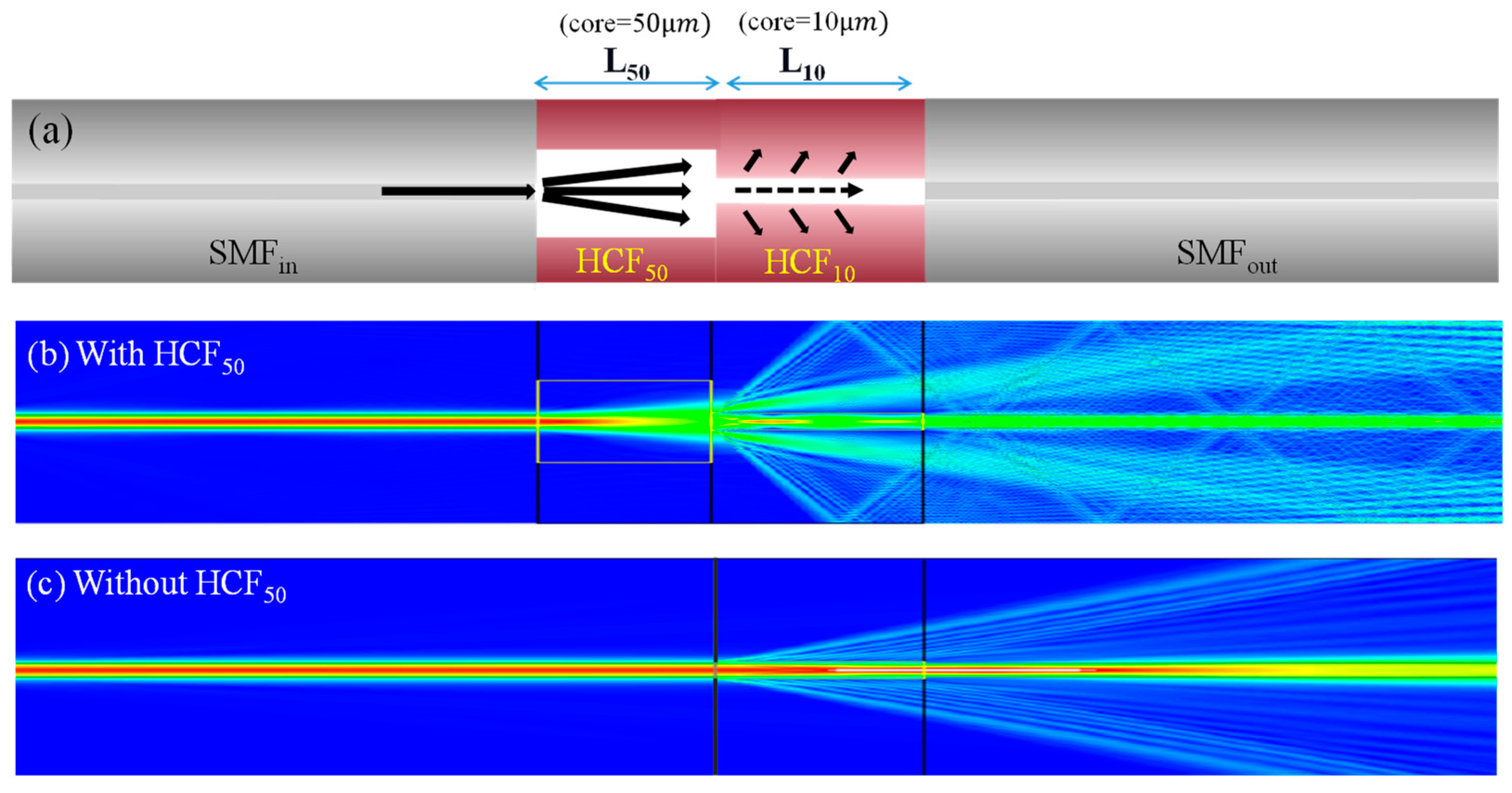
In this study, a head input SMFin was first fusion spliced to a length of L50 of HCF50 and, at the end of the HCF50, successively splicing another section HCF10 with a length of L10. The inner air-core diameters of the HCF50 and HCF10 are 50 μm and 10 μm, respectively, and their outer silica-cladding is 125 μm. Finally, an output SMFout collects the optical signal to be measured. Figure 1a schematic plots the configuration of the proposed leaky-guided FMZI splits the leaky-core mode and cladding modes for the interference. To understand more about the section of the HCF50 and how it assists in splitting the optical light into two paths of the leaky core and cladding beams that launch into the HCF10 with appropriate intensities. The FDTD method of the RSoft BeamPROP tool (Synopsys, Inc., located in Mountain View, CA, USA) is useful for theoretically calculating and analyzing optical light characteristics in photonic structures. The used simulation tool, a scalar beam propagation method (BPM) in the RSoft suite, is suitable for calculating light propagation along the z-axis in complicated fiber structures and optical waveguides. In the calculation, the core and cladding diameters of the SMF are set to be 8.2 μm and 125 μm, respectively, and their RIs of the core and cladding are based on the Sellmeier equations of the dispersion, as shown below [23].

Figure 1.
(a) Schematic diagram of the proposed HCF-based LGFW-FMZI. The FDBPM simulation results of optical field distribution of light for the proposed structure (b) with and (c) without the segment of the HCF50 beam splitter.
Figure 1b shows the BPM simulation results of the optical field distribution of light propagating at fiber communication wavelength (λ) of 1550 nm along the proposed successive segment of HCFs waveguide when the hollow core is set to be air (n = 1). Figure 1b shows that the optical mode field expands in section HCF50 and splits into two paths, launching into the HCF10 section. In the HCF10 segment, the RI of its core is lower than that of the cladding, and a leaky light appears in this section to simultaneously have the core and cladding modes for obtaining interference to the SMFout. From the optical mode field distribution of light in Figure 1b, the superposition of the optical waves produces constructive and destructive optical fields. On the contrary, Figure 1c plots the optical field distribution of light without the segment of the HCF50 beam splitter. The leaky light also appears in the HCF10 section to generate core and cladding paths; however, much of the optical intensity is concentrated in the core of the tiny HCF10, not to achieve excellent interferences. Therefore, we believe that by appropriately arranging the lengths of HCF50, HCF10, and RI of the core, the results can obtain excellent interference characteristics with ultrahigh ER and arbitrary FSR in the optical interference spectra of the proposed LGFW-FMZI.
In the studied leaky-guided FMZI, the optical intensity of cladding and core modes are denoted as Icl and Ico, respectively. The total intensity of the interference beam is denoted as IFMZI, defined by the following Equation (3) [21].
where L10 is the length of HCF10, which is the interference length, and λ is the wavelength of the optical light. is the effective index difference and and present the effective refractive index of cladding and core modes generating the interference, respectively. When the optical phase difference ((2π/λ)·Δneff·L10) matches the condition of destructive interference, the dip wavelength () of minimum power can be deduced as Equation (4) below.
Here, m is the order of interferential mode, and it is an integer. The FSR of the FMZI means the wavelength difference in two continuous interference dips or peaks between the front and rear. Afterwards, we can utilize the relationship of interference phase difference to derive FSR, which can be expressed as Equation (5).
where λ1 and λ2 represent the wavelengths of two adjacent interference dips. To achieve optimal interference, the contrast of the interference fringes should be maximized, meaning the amplitude of the interference term should be at its maximum. In Equation (3), the amplitude of the interference term that reaches its maximum value when the . Thus, for the best interference fringe visibility, the intensities of the core mode and the cladding mode should be very close.
3. Simulation and Experimental Results
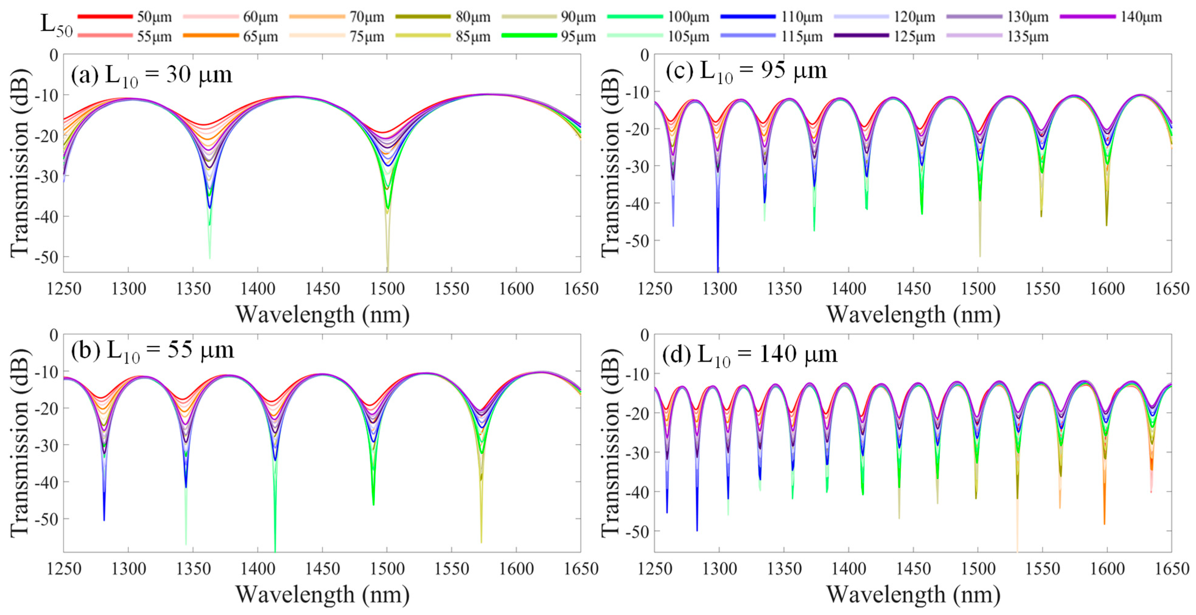
In the simulation, we arbitrarily adjust the lengths of HCF50 (L50) and HCF10 (L10) to vary the core mode (Ico) and cladding mode light intensity (Icl) for the analysis of the interference spectra in the proposed successive segment HCF structure. To achieve the optimal interference results, we adjusted the lengths of segments HCF50 and HCF10 to make the Ico approach the Icl. As the structure is shown in Figure 1a, a Gaussian power light source was set with a wavelength range from λ = 1250 nm to 1650 nm (resolution: 0.8 nm) that is launched from the input SMFin. Here, all the refractive indices of the used fiber core and silica cladding are considered chromatic dispersion over such a wide wavelength range over 400 nm. Figure 2 illustrates the simulation results of interference spectra for the different length combinations of the HCF50 and the HCF10 in the leaky-guided FMZI structure. Here, the core of HCF is air (n = 1). The optimal interference patterns are obtained by varying the length L50 from 50 to 140 μm with an interval of 5 μm when fixing the length L10 of HCF10. The results are shown in Figure 2a–d with different L10 fixed at 30 μm, 55 μm, 95 μm, and 140 μm, respectively. The ERs of the optical interference fringes are greatly diverse by varying the L50. We can analyze the interference fringes and demonstrate that the FSR is individually dominated by the L10 of HCF10, which generates the interference spectra. However, the length L50 of HCF50 acts as a fiber beam splitter for different beam expansions that greatly modify the ER of interference spectra.
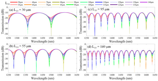
Figure 2.
Simulated interference spectra for different combinations of L50 and L10 in the proposed leaky-guided FMZI with varying L50 from 50 to 140 μm and fixed L10 are (a) 30 μm, (b) 55 μm, (c) 95 μm, and (d) 140 μm, respectively.
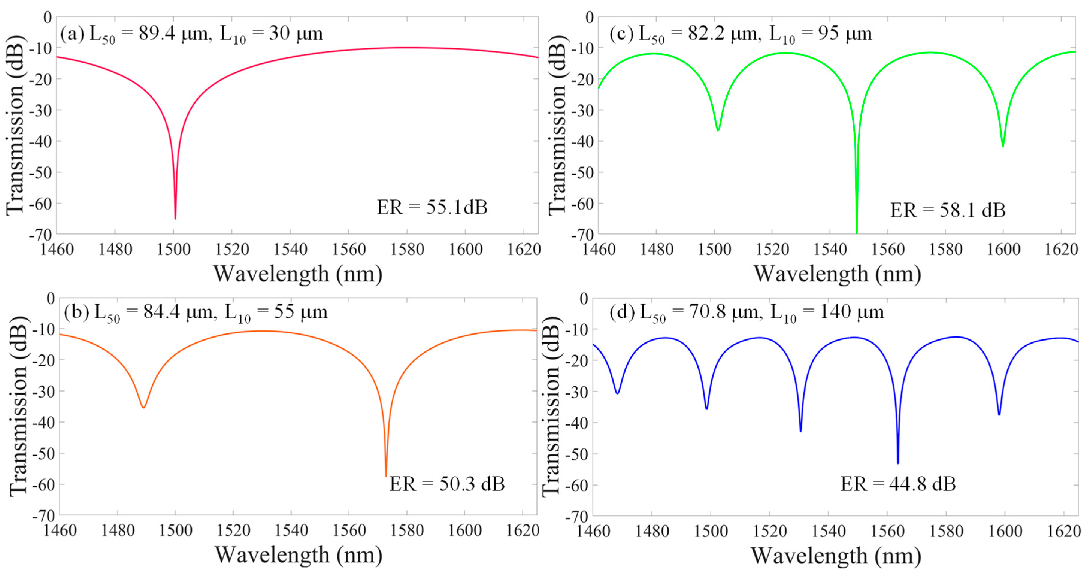
To obtain the optimal interference for the Ico, which is almost the same as the Icl, we further improve the resolution of the length L50, with an interval of 0.2 μm being one of the values of L50 that can obtain the best ER of interference spectra over the wavelength range covered by the S + C + L optical fiber communication bands, as shown in Figure 3.
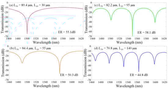
Figure 3.
Simulation results for the best ultrahigh ER around 50 dB of the optimal interferences at L10 fixed at (a) 30 μm, (b) 55 μm, (c) 95 μm, and (d) 140 μm when the L50 is 89.4 μm, 84.4 μm, 82.2 μm, and 70.8 μm, respectively. (Note: the monitored wavelength range is 1460 nm–1625 nm).
Figure 3 shows the optimal ERs of the optimal interferences that can be obtained at each case of L10 fixed at 30 μm, 55 μm, 95 μm, and 140 μm when the beam splitter HCF50 with L50 is 89.4 μm, 84.4 μm, 82.2 μm, and 70.8 μm, respectively. One can see that the ER over 50 dB (around λ = 1550 nm) can be almost achieved by arranging the lengths of the HCF50 and HCF10.
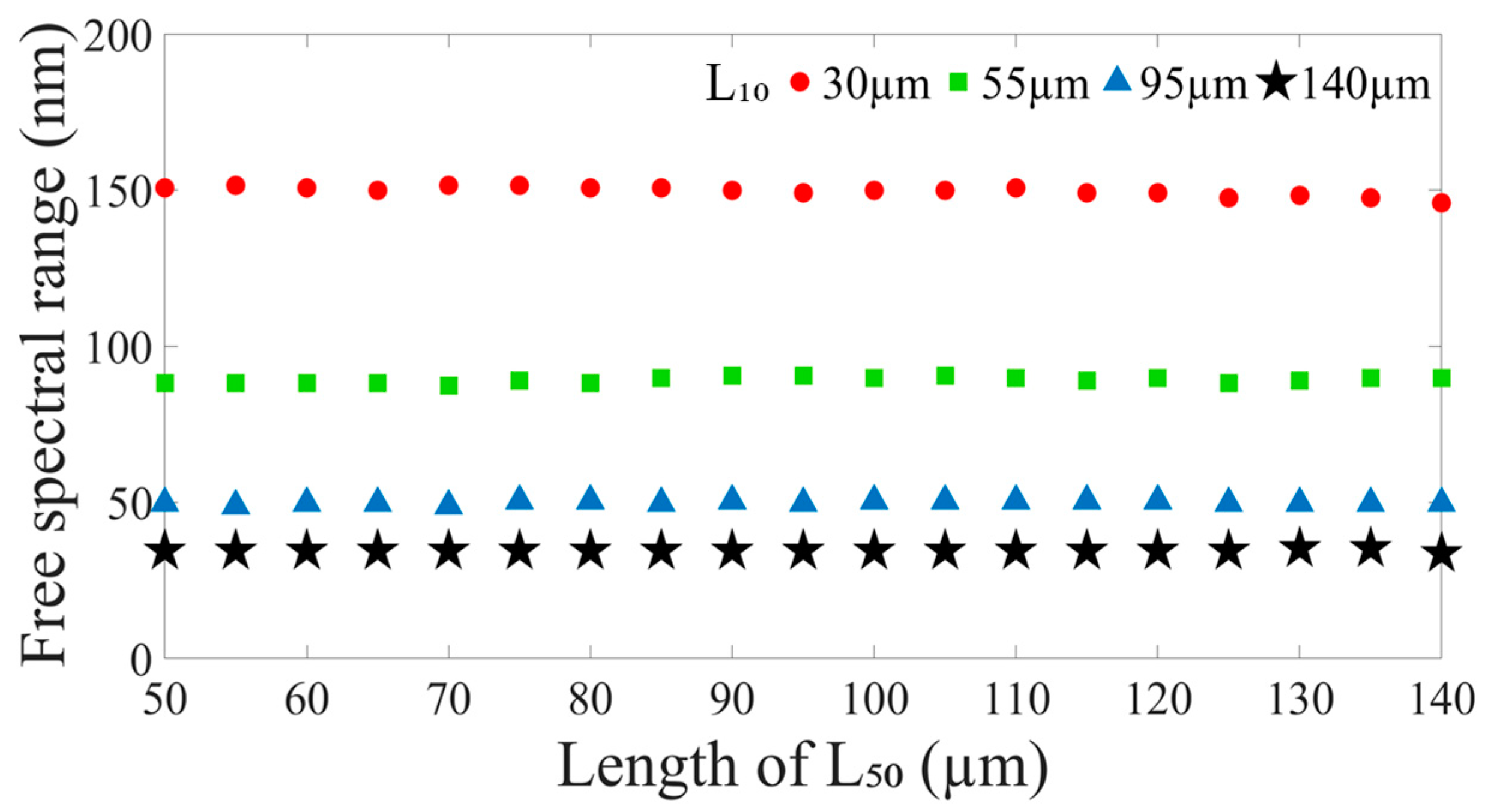
From the above simulation results (Figure 2 and Figure 3), Figure 4 shows the FSRs of the optical interference in the proposed leaky-guided FMZI with varying lengths of HCF50 (L50) by fixing the HCF10 (L10). We can see that no matter the L50, it does not impact the FSR of the interference spectra. The results display the FSR is only affected by the L10 of the HCF10. Once the length of HCF10 is determined, the FSR is almost constant. Figure 4 shows the FSR values at the wavelength dips close to λ = 1550 nm. The results demonstrate that the FSRs are 149.9 nm, 89.8 nm, 49.7 nm, and 34.5 nm when the L10 are 30 μm, 55 μm, 95 μm, and 140 μm, respectively. Therefore, one can adjust the length of L10 to gain the desired FSR in the interference spectra.

Figure 4.
The FSR of the proposed leaky-guided FMZI with varying L50 of HCF50 when the L10 of HCF10 is fixed at ( ) 30 μm, (
 ) 55 μm, (
 ) 95 μm, and (
 ) 140 μm, respectively.
) 30 μm, () 55 μm, () 95 μm, and () 140 μm, respectively.
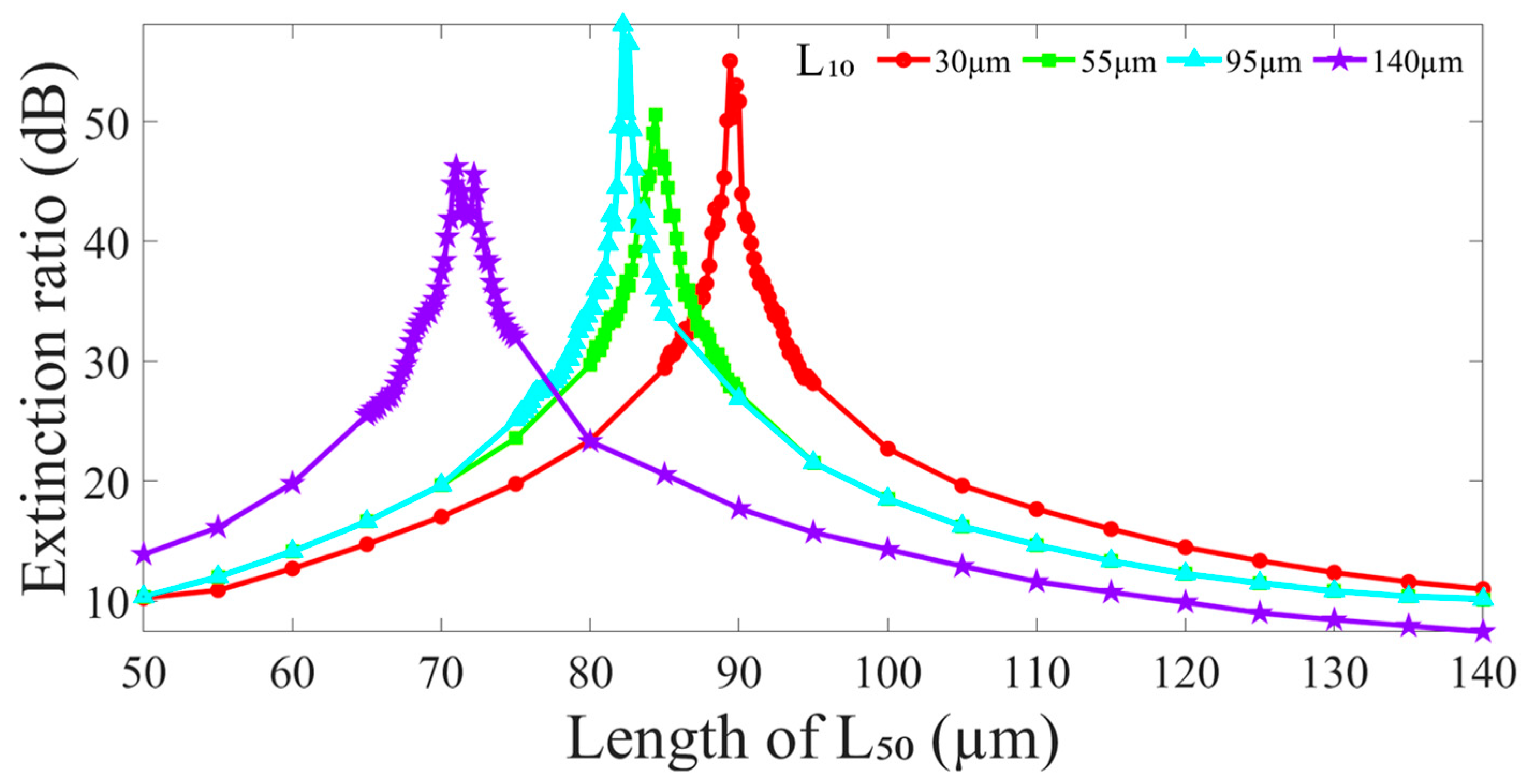
In addition, Figure 5 indicates the ERs of the proposed leaky-guided FMZI with varying L50 of HCF50 when the L10 of HCF10 is fixed at 30 μm, 55 μm, 95 μm, and 140 μm, respectively. From the results, we can observe the conditions of the highest ER of the interferences (the peaks in Figure 5) that occur in every specific L50 at each L10. The collocation of optimal interference conditions occurring in longer L10 would be arranged with a shorter L50, and vice versa. Here, we also can see the proposed structure with a longer L50 over 120 μm cannot have useful interference ERs. This is because a long L50 spreads the optical light more into the cladding of HCF10, which greatly reduces light intensity in the core of HCF10 to make the difference between the Ico and Icl even greater. Additionally, the optical light in the leaky core of HCF10 gradually leaks out into the silica cladding through the increasing propagation distance. Thus, the much greater difference between the Ico and Icl results in a poor ER. It is obvious that to fabricate such a high-quality interferometer, the length required accuracy of each section in the HCF’s connection configuration is exceptionally strict.

Figure 5.
The ERs of interference fringe around λ = 1550 nm in the proposed leaky-guided FMZI with varying L50 of HCF50 when the L10 of HCF10 is fixed.
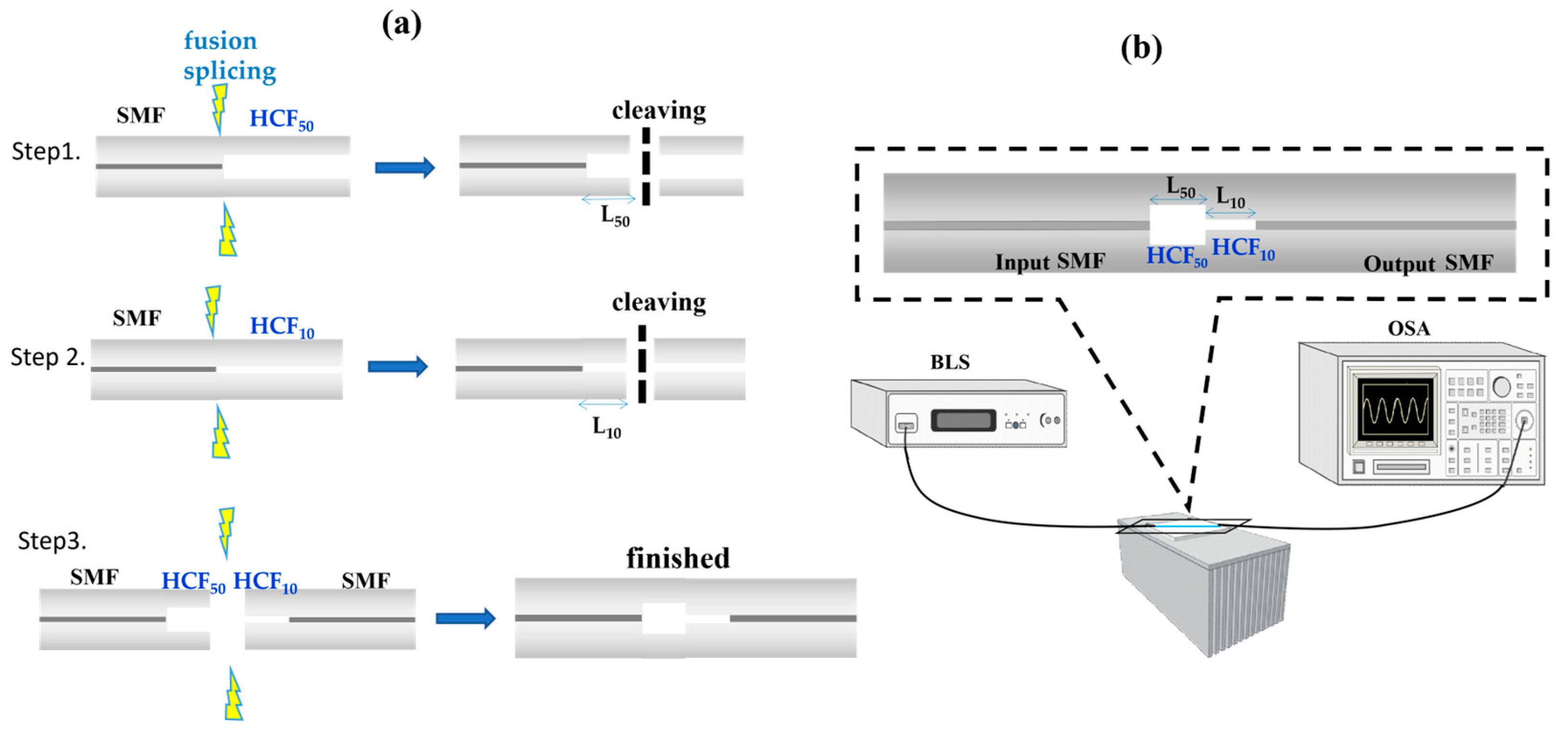
To verify the optimal structure proposed by theoretical simulation, we perform the experiments. Our process begins with the crucial step of cleaving the SMF, which has an outer diameter of 125 μm and an inner diameter of 8.2 μm. This is followed by the fusion splicing with HCF50 and the cleaving of an appropriate length (L50) to approach the optimal L50. Another segment based on the HCF10 follows the same steps. Finally, the two segments, the SMF-HCF50 and HCF10-SMF, are aligned with their optimal lengths (L50 and L10) and then arc discharge of fusion splicing. The fabrication flow chart is displayed in Figure 6a. This method ensures precise fiber connections and provides a reliable foundation for subsequent experiments. Figure 6b illustrates the experimental setup for spectral measurement. A broadband light source (BLS) with wavelengths of 1250~1650 nm is incident from input-SMF to the HCF50-HCF10, inducing the cladding mode and interfering with the leaky-guided core mode in output-SMF. The reliability of the optical spectrum analyzer (OSA) in measuring the interference spectra ensures the accuracy of the results.
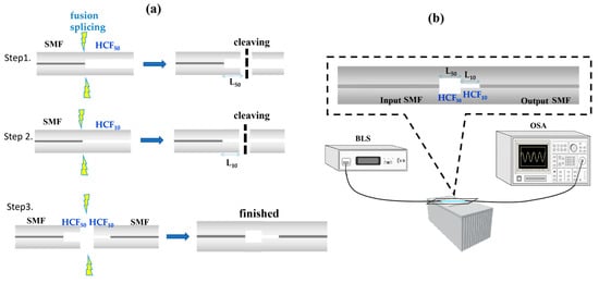
Figure 6.
Schematic diagrams of (a) the fabrication steps and (b) the measurement system.
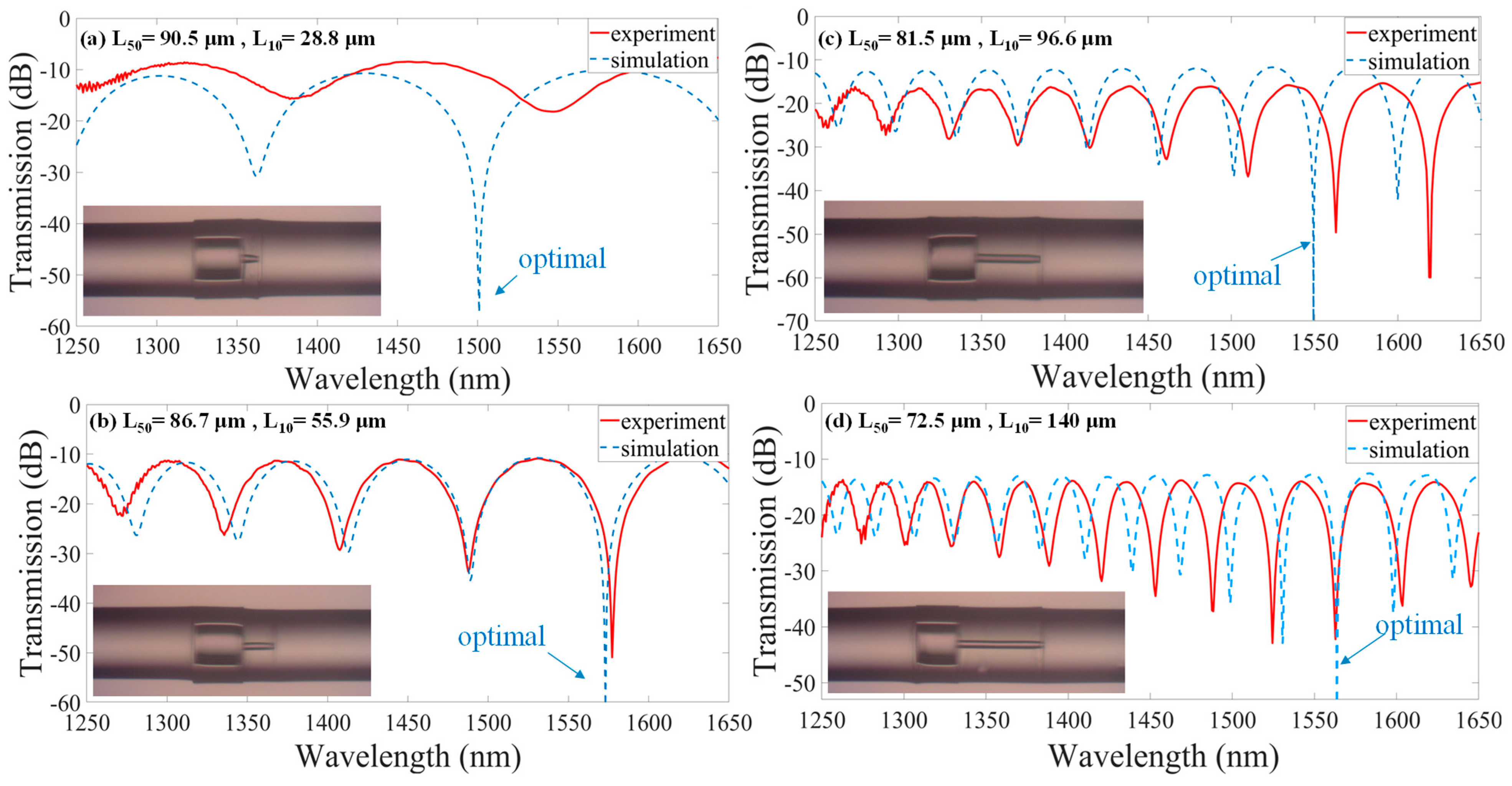
Figure 7 presents the theoretical simulation and experimental results for the different combinations of the L50 and L10 for the optimized spectral interference. Their optical interference spectra are compared and analyzed. The red solid lines represent the experimental data and the highest ER over 40 dB achieved, while the blue dashed lines represent the simulation results of the optimal condition. The insets show their corresponding microscope photographs of the fabricated FMZIs. The values of (a) 90.5/28.8 μm, (b) 86.7/55.9 μm, (c) 81.5/96.6 μm, and (d) 72.5/140 μm are measured by the optical microscope with an error of ±1 μm. We can see that the experimental and simulation results are in good agreement in Figure 7b–d except Figure 7a. The fabricated structure of the lengths L50 and L10 demonstrates that the simulation work is helpful for the experiment approaching optimal performance. It is worth noting that there is a significant discrepancy between the theoretical value and the experimental value in Figure 7a with such a tiny L10. This is because the production accuracy of the ultrashort L10 is more difficult to achieve. The required accuracy of the lengths of L50 as well as the L10 in each section of the configuration is especially rigorous. Thus, using the commercial fiber cleaver and general fusion splicer to fabricate the proposed HCF-based fiber device extremely precisely in the experiment is not easy. However, the developed simulation work for the refined fiber interferometers is significantly valuable for the design, fabrication, and operation. In practical applications of the proposed LGFW-FMZI, we can control the FSR by altering the length of HCF10. Once the FSR is determined, the length of HCF50 can be selected to satisfy the requirements for the designed fiber optic interferometer. This makes the designed devices more flexible and practical. Therefore, once the optimally designed structure is obtained, the proposed ultrahigh extinction ratio fiber device can be designed for some fiber passive devices in fiber communications and fiber laser technology applications, like a band-pass filter and a wavelength-selective filter. Moreover, creating a microhole in the HCF50 section is accessible using an fs laser. One can introduce different materials into the HCF [6]. For example, the specimens of chemical and biological detection. Especially for measuring some precious and rare materials since the volume required is merely picoliter level. Due to the high fringe visibility that can achieve a high-resolution measurement, the proposed approach can be applied to measure materials with high accuracy, demonstrating its adaptability to various measurements.
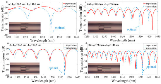
Figure 7.
Comparison of the optical interference spectra of the simulation (optimal) and experimental results with fabricated L50/L10 (a) 90.5/28.8 μm, (b) 86.7/55.9 μm, (c) 81.5/96.6 μm, and (d) 72.5/140 μm, respectively. Their insets include a corresponding microscopic image of the fabricated devices.
It is particularly mentioned that silica fiber’s thermal expansion coefficient (a) is low, about 5 × 10⁻⁷ (1/K), its Young’s modulus is very high, approximately 70 GPa, and inelastic in such a tiny HCF of tens micrometers. Therefore, it is insensitive to thermal, bending, and strain parameters when non-filling material in the hollow core. Such features would benefit from avoiding cross-sensitivity in sensing technology.
4. Conclusions
We have proposed a novel, ultrahigh ER and ultracompact leaky-guided FMZI based on a tiny HCF10 front connected with a large core of a 50 μm HCF50 beam splitter. The main interference region in the proposed leaky-guided FMZI is the HCF10 section. The operated HCF50 expands the optical beam and splits into two paths, launching into the HCF10 section. It assists the interference section of the HCF10 to improve the optimal interference (ultrahigh ER). By varying the micro-lengths of the HCF50 (L50) and HCF10 (L10) sections, we first demonstrated the light splitting and combining mechanisms on the designed FMZI. Simulation and experimental results indicate that the L10 of the HCF10 primarily influences the FSRs of the interference transmission spectra. However, the ERs would be affected by the L50 of beam splitter HCF50 when the L10 of HCF10 is fixed. Based on the simulation results, the greatest performance of ultrahigh ER, generally over 50 dB, can be achieved by the structures of combination: L50/L10 of 89.4 μm/30 μm, 84.4 μm/55 μm, 82.2 μm/95 μm, and 70.8 μm/140 μm. For each designed FMZI with a fixed L10, there will be a specific L50 to be matched to generate the optimal interference. However, the required accuracy of the lengths of L50 as well as the L10 in each section of the configuration is very exceptionally strict. Even so, the experimental and simulation results are still in acceptable agreement to demonstrate that the work is still valuable for the experiment approaching optimal performance. Finally, by appropriately varying the lengths L50 of the beam splitter and L10 of the interference length, the excellent interference spectrum characteristics with an ultrahigh ER and arbitrary FSR of the optical interference spectra in the proposed ultracompact LGFW-FMZI have been proposed. We believe the proposed fiber-optic device would benefit sensing and fiber communications technology applications.
Author Contributions
Data curation, Y.-H.L. and R.-X.L.; fabrication, Y.-H.L. and R.-X.L.; formal analysis, C.-L.L. and Y.-H.L.; funding acquisition, C.-L.L.; investigation, C.-L.L. and Y.-H.L.; methodology, C.-L.L.; software, Y.-H.L.; supervision, C.-L.L.; writing—review and editing, C.-L.L. and Y.-H.L. All authors have read and agreed to the published version of the manuscript.
Funding
This research was funded by The National Science and Technology Council of Taiwan, 110-2221-E-239-025-MY2 and 112-2221-E-239-028.
Data Availability Statement
Data are contained within the article.
Conflicts of Interest
The authors declare no conflicts of interest.
References
- Kieu, K.; Schneebeli, L.; Norwood, R.A.; Peyghambarian, N. Integrated liquid-core optical fibers for ultraefficient nonlinear liquid photonics. Opt. Express 2012, 20, 8148–8154. [Google Scholar] [CrossRef] [PubMed]
- Liu, B.H.; Jiang, Y.X.; Zhu, X.S.; Tang, X.L.; Shi, Y.W. Hollow fiber surface plasmon resonance sensor for the detection of liquid with high refractive index. Opt. Express 2013, 21, 1003–1008. [Google Scholar] [CrossRef] [PubMed]
- Liu, Y.; Zhao, C.; Zhang, Y.N.; Ma, G.; Li, X.; Zhao, Y. Electrically tunable optical fiber device based on hollow-core fiber infiltrated with liquid crystal. Sens. Actuators A Phys. 2021, 318, 112500. [Google Scholar] [CrossRef]
- Lee, C.L.; Chang, Y.C.; Ma, C.T.; Chen, C.H.; Hsiang, W.W. Chemical modified fiber Fabry–Pérot interferometer by silver mirror reaction for hot-wire anemometry. Sens. Actuators A Phys. 2022, 334, 113364. [Google Scholar] [CrossRef]
- Lv, Z.; Wang, S.; Jiang, J.; Liu, K.; Zhang, X.; Qi, X.; Wang, X.; Liu, T. Long-sensing-length strain sensor based on optical fiber Fabry-Perot interferometer with HCF-SMF structure. IEEE Photonics J. 2019, 11, 6803408. [Google Scholar] [CrossRef]
- Lee, C.L.; Chang, H.J.; You, Y.W.; Chen, G.H.; Hsu, J.M.; Horng, J.S. Fiber Fabry-Pérot interferometer based on air-bubbles/liquid in hollow core fibers. IEEE Photon. Technol. Lett. 2014, 26, 749–752. [Google Scholar] [CrossRef]
- Costa, G.K.B.; Gouvêa, P.M.P.; Soares, L.M.B.; Pereira, J.M.B.; Favero, F.; Braga, A.M.B.; Palffy-Muhoray, P.; Bruno, A.C.; Carvalho, I.C.S. In-fiber Fabry-Perot interferometer for strain and magnetic field sensing. Opt. Express 2016, 24, 14690–14696. [Google Scholar] [CrossRef]
- Zhu, C.C.; Yu, Y.S.; Zhang, X.Y.; Chen, C.; Liang, J.F.; Liu, Z.J.; Meng, A.H.; Jing, S.M.; Sun, H.B. Compact Mach–Zehnder interferometer based on tapered hollow optical fiber. IEEE Photon. Technol. Lett. 2015, 27, 1277–1280. [Google Scholar] [CrossRef]
- Liu, N.; Hu, M.; Sun, H.; Gang, T.; Yang, Z.; Rong, Q.; Qiao, X. A fiber-optic refractometer for humidity measurements using an in-fiber Mach–Zehnder interferometer. Opt. Commun. 2016, 367, 1–5. [Google Scholar] [CrossRef]
- Zhao, Y.; Cai, L.; Li, X.G. In-fiber modal interferometer for simultaneous measurement of curvature and temperature based on hollow core fiber. Opt. Laser Technol. 2017, 92, 138–141. [Google Scholar] [CrossRef]
- Liu, S.; Zhang, H.; Li, L.; Xiong, L.; Shum, P. Liquid core fiber interferometer for simultaneous measurement of refractive index and temperature. IEEE Photon. Technol. Lett. 2019, 31, 189–192. [Google Scholar] [CrossRef]
- Dong, L.; Gang, T.; Bian, C.; Tong, R.; Wang, J.; Hu, M. A high sensitivity optical fiber strain sensor based on hollow core tapering. Opt. Fiber Technol. 2020, 56, 102179. [Google Scholar] [CrossRef]
- Marrujo-García, S.; Hernández-Romano, I.; Torres-Cisneros, M.; May-Arrioja, D.A.; Minkovich, V.P. Temperature-independent curvature sensor based on in-fiber Mach-Zehnder interferometer using hollow-core fiber. J. Light. Technol. 2020, 38, 4166–4173. [Google Scholar] [CrossRef]
- Gao, R.; Jiang, Y.; Zhao, Y. Magnetic field sensor based on anti-resonant reflecting guidance in the magnetic gel coated hollow core fiber. Opt. Lett. 2012, 39, 6293–6296. [Google Scholar] [CrossRef]
- Hou, M.; Zhu, F.; Wang, Y.; Wang, Y.; Liao, C.; Liu, S.; Lu, P. Antiresonant reflecting guidance mechanism in hollow-core fiber for gas pressure sensing. Opt. Express 2016, 24, 27890–27898. [Google Scholar] [CrossRef]
- Liu, S.; Tian, J.; Liu, N.; Xia, J.; Lu, P. Temperature insensitive liquid level sensor based on antiresonant reflecting guidance in silica tube. J. Light. Technol. 2016, 34, 5239–5243. [Google Scholar] [CrossRef]
- Sun, H.; Luo, H.; Wu, X.; Liang, L.; Wang, Y.; Ma, X.; Zhang, J.; Hu, M.; Qiao, X. Spectrum ameliorative optical fiber temperature sensor based on hollow-core fiber and inner zinc oxide film. Sens. Actuators B Chem. 2017, 245, 423–427. [Google Scholar] [CrossRef]
- Zhang, X.; Pan, H.; Bai, H.; Yan, M.; Wang, J.; Deng, C.; Wang, T. Transition of Fabry–Perot and antiresonant mechanisms via a SMF-capillary-SMF structure. Opt. Lett. 2018, 43, 2268–2271. [Google Scholar] [CrossRef]
- Liu, D.; Wu, Q.; Mei, C.; Yuan, J.; Xin, X.; Mallik, A.K.; Wei, F.; Han, W.; Kumar, R.; Yu, C.; et al. Hollow core fiber-based interferometer for high-temperature (1000 °C) measurement. J. Light. Technol. 2018, 36, 1583–1590. [Google Scholar] [CrossRef]
- Jung, Y.; Lee, S.; Lee, B.H.; Oh, K. Ultracompact in-line broadband Mach-Zehnder interferometer using a composite leaky hollow-optical-fiber waveguide. Opt. Lett. 2008, 33, 2934–2936. [Google Scholar] [CrossRef]
- Lee, C.-L.; Zhuo, W.-R.; Liu, T.-K. Highly modulated in-fiber Mach-Zehnder interferometer based on an ultracompact leaky-guided liquid core. Sensors 2022, 22, 808. [Google Scholar] [CrossRef] [PubMed]
- Lee, C.-L.; Lu, Y.; Chen, C.-H.; Ma, C.-T. Microhole-pair hollow core fiber Fabry-Perot interferometer micromachining by a femtosecond laser. Sens. Actuators A Phys. 2020, 302, 111798. [Google Scholar] [CrossRef]
- Jeong, H.; Oh, K. Theoretical analysis of cladding-mode waveguide dispersion and its effects on the spectra of long-period fiber grating. J. Light. Technol. 2003, 21, 1838–1845. [Google Scholar] [CrossRef]
Disclaimer/Publisher’s Note: The statements, opinions and data contained in all publications are solely those of the individual author(s) and contributor(s) and not of MDPI and/or the editor(s). MDPI and/or the editor(s) disclaim responsibility for any injury to people or property resulting from any ideas, methods, instructions or products referred to in the content. |
© 2024 by the authors. Licensee MDPI, Basel, Switzerland. This article is an open access article distributed under the terms and conditions of the Creative Commons Attribution (CC BY) license (https://creativecommons.org/licenses/by/4.0/).