1. Introduction
The worldwide energy crisis evokes an unprecedented enthusiasm for the development of an apparatus for efficient light-to-electricity conversion. Dye-sensitized solar cells (DSSCs), together with organic photovoltaics (OPVs), are generally considered two types of third-generation energy-harvesting devices. There is an enthusiasm for engineering the electrolytes, i.e., from non-aqueous systems to aqueous ones [
1,
2,
3,
4]. As another key component in DSSCs, the photosensitizer is responsible for light absorption and the subsequent electron-transfer reactions, and its quality thus determines the power conversion efficiency (PCE). Inorganic semiconductor quantum dots (ISQDs), such as CdS, CdSe, and PbS, represent an important class of photosensitizers. Compared to DSSCs employing Ru–polypyridine complexes or low-molecular-weight organic dyes as photosensitizers, ISQD-sensitized solar cells (ISQDSCs) are expected to have low costs and relatively high PCE [
5,
6]. A big disadvantage of ISQDSCs, however, is their intrinsic toxicity caused by the presence of heavy metal elements in ISQDs. Developing new types of quantum dots that are environmentally benign is necessary for further realizing the potential of this new branch of DSSCs.
In recent years, carbon quantum dots (CQDs), which are photoluminescent (PL) carbon nanomaterials that have spherical shapes and sizes below 10 nm, have received extensive attention due to their easy preparation and tunable PL properties [
7]. More importantly, CQDs are nontoxic for both environment and biological systems, which is advantageous over ISQDs. Based on these virtues, CQDs exhibit great potential applications in various fields and have been used in bioimaging [
8], ion detection [
9,
10], PL inks [
11,
12,
13], and coatings for light-emitting diodes (LEDs) [
14]. Attempts to integrate CQDs in photovoltaics have also been made [
15,
16,
17]. Specifically in DSSCs, CQDs have been used as co-sensitizers together with ISQDs [
18] or organic dyes [
19], and the CQD-based solar cells were found to show superior performances.
Applying CQDs as the sole photosensitizer in DSSCs, compared to using CQDs as an additive in mixed photosensitizers, is more interesting but also more challenging. In a seminal work, Mirtchev et al. integrated TiO
2 photoanode with CQDs obtained from acid dehydration of γ-butyrolactone, and a PCE of 0.13% was obtained [
20]. Zhang et al. also reported the preparation of DSSCs using N-doped CQDs as photosensitizers, and the PCE was found to be the same as that reported by Mirtchev et al. (i.e., 0.13%) [
21]. Briscoe et al. used three different types of biomass-derived CQDs as photosensitizers, which were hybridized with ZnO as photoanodes. However, the highest PCE of the solar cells is even lower (0.077%) [
22]. Recently, Margraf et al. reported CQD-based DSSCs with a PCE of 0.24% [
23]. They found that the pH value of the aqueous solution where CQDs and TiO
2 photoanodes were integrated plays an important role in governing the performance of the solar cell, while extending the light absorption of CQDs towards longer wavelengths does not help. Wang et al. also prepared CQD-based DSSCs by integrating CQDs and TiO
2 photoanodes in acetone. A PCE of 0.79% was obtained [
24]. There are also research interests on edge-bound nanometer-size graphene pieces with lateral dimensions less than 100 nm termed graphene quantum dots (GQDs), which can be viewed as close relatives of CQDs. In this case, two works using GODs as photosensitizers in DSSCs have been presented. Yan et al. synthesized GQDs from small organic molecules, and integrated them with TiO
2 photoanodes in a toluene/ethanol mixture [
25]. The solar cell exhibits a considerable open-circuit voltage (
VOC, 0.48 V) and fill factor (
FF, 0.58). However, it suffers from low short-circuit current density (
JSC, 0.2 mA/cm
−2), which gives a final PCE of ~0.06%. Ji et al. prepared GQDs on TiO
2 via a Scholl reaction from a preadsorbed polyphenylene precursor functionalized with surface anchoring groups, and a PCE of 0.87% was obtained [
26], which is slightly higher compared to that reported for the solar cells sensitized by CQDs.
It is clear that research on CQD-sensitized solar cells (CQDSCs) is still in its infancy. Although great efforts have been devoted as mentioned above, further improvement of the PCE is necessary. More importantly, the use of acetone in the preparation of the solar cell with the highest PCE reported to date (0.79%) [
24] is not environmentally benign and is incompatible with the majority of the CQDs, which are water-soluble. On the other hand, the GQD-sensitized solar cells, though exhibiting a slightly higher PCE (0.87%) [
26] than that of CQDSCs, suffer from multi-step, time-consuming synthesis of the photosensitizers, which will significantly raise the costs of resulting DSSCs.
One big challenge causing the unsatisfactory PCE of CQDSCs is the low affinity between TiO
2 (or ZnO) and CQDs. In previous studies, the CQDs were always synthesized first, followed by integration with the photoanode by post-adsorption [
20,
22,
23,
24,
25,
26] or hydrothermal treatment [
21] in bulk solutions. This simple treatment leads to a poor adsorption of the CQDs onto the TiO
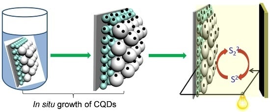
2-coated photoanode. Herein, we provide a new engineering method for a CQD-based photoanode, where CQDs were grown in situ onto the TiO
2 surface. We will show that, by using this strategy, the surface coverage of TiO
2 by CQDs can be significantly improved, leading to an impressive performance of the solar cell.
2. Results and Discussion
For the in situ growth of CQDs, the TiO
2-coated fluorine-doped tin oxide (FTO) glass was vertically immersed in a 10 mL aqueous solution containing citric acid (CA, 0.5 mol·L
−1) and ethanediamine (EDA, 0.5 mol·L
−1). The system was then sealed in an autoclave and pyrolized at 180 °C for 24 h. After that, the as-prepared CQDs/TiO
2 was rinsed with deionized water thoroughly and dried in air. Here, CA and EDA were selected as the precursors for CQD production because the synthetic procedures of CQDs from this combination have been well-established [
13]. The CQDs/TiO
2 hybridized photoanode (abbreviated to CQDs/TiO
2 hereafter) appears as a dark-brown film (inset of
Figure 1A), which is in sharp contrast to the control experiment where the TiO
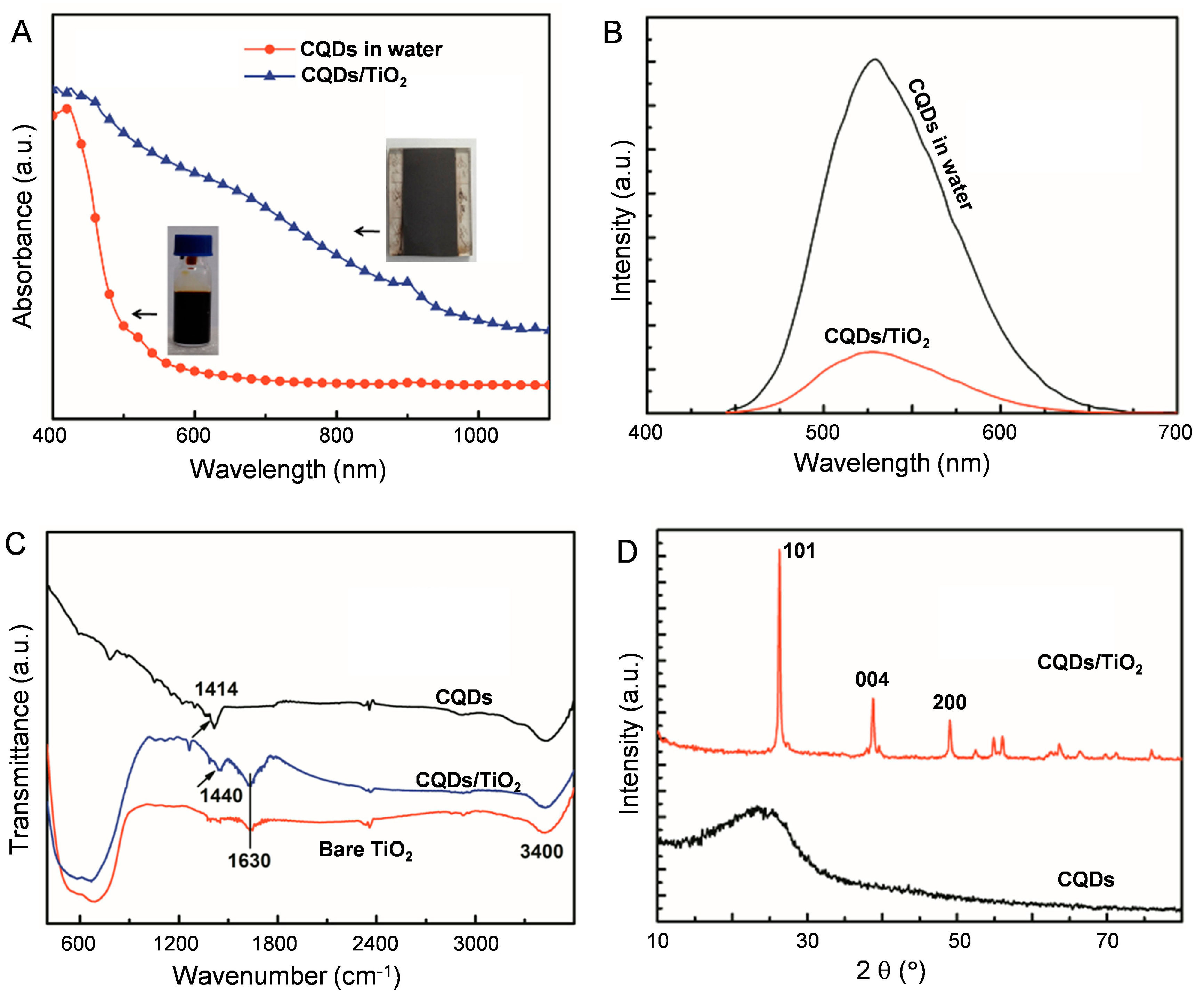
2 photoanodes were found to be only slightly colored if physical adsorption was applied. This indicates that, by adopting the in situ growth method, the amount of CQDs anchored on the photoanode has been significantly improved. From the UV-vis-NIR absorption spectra, it can be seen that CQDs/TiO
2 exhibits extensive optical absorption throughout the visible and NIR regions, while the absorptions of CQDs alone are mainly located in the UV region (
Figure 1A). PL spectra indicate that, after being integrated onto the TiO
2 photoanode, the fluorescence of CQDs is quenched (
Figure 1B). The shift of the absorption towards longer wavelengths and the fluorescence quenching of CQDs on the photoanode indicate a more compact arrangement of the dots in the film state. The lower emission intensity of CQDs on the photoanode compared to those in the bulk solution is also indicative of a lower recombination rate of the excitons, which is preferable when using the materials as photosensitizers [
27].
The changes in the optical properties of CQDs after being integrated with TiO
2 might also be caused by the interactions between them. To test this possibility, FTIR measurements were carried out, as shown in
Figure 1C. The peak at 1414 cm
−1 assigned to the C–O stretching vibration for CQDs shifts to 1440 cm
−1 in CQDs/TiO
2, which could be caused by the interaction between CQDs and TiO
2 [
28]. Peaks at 1630 cm
−1 and 3400 cm
−1, which appear in both bare TiO
2 and CQDs/TiO
2, could be caused by vibrations of surface adsorbed water. From X-ray diffraction (XRD) measurements shown in
Figure 1D, mainly peaks related to anatase TiO
2 can be detected (2
θ: 25.1°, 38.1°, 47.9°) in CQDs/TiO
2. CQDs alone only show a broad band centered around 25°, which indicates the low crystallinity of the synthesized CQDs.
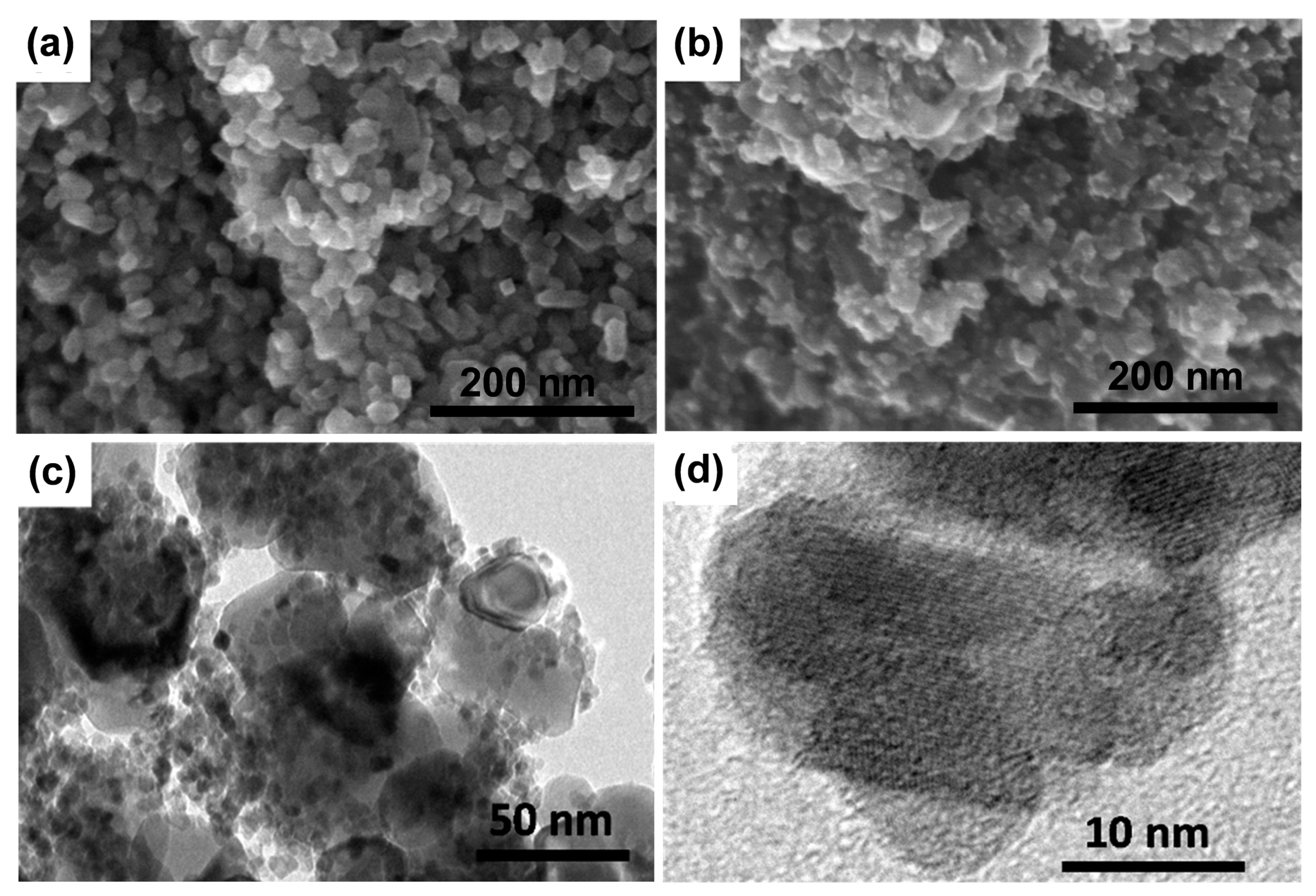
The morphologies of the TiO
2-coated photoanode before and after CQDs hybridization have been investigated by scanning electron microscopy (SEM) observations. The TiO
2 nanoparticles organized on FTO glass into a porous structure (
Figure 2a). When CQDs were integrated with the TiO
2-coated photoanode, the presence of CQDs can be confirmed (
Figure 2b). Importantly, the TiO
2 film remains porous after it is hybridized with CQDs without obvious pore blocking, which will facilitate the penetration of the electrolyte in the solar cell. To get further details, the CQD-sensitized photoanode was further checked by transmission electron microscopy (TEM) observations (
Figure 2c,d). It can be seen that the CQDs grown in situ on TiO
2 surfaces have sizes of 2–6 nm, and most of them distribute evenly. The lack of severe aggregation highlights the advantage of the in situ growth method.
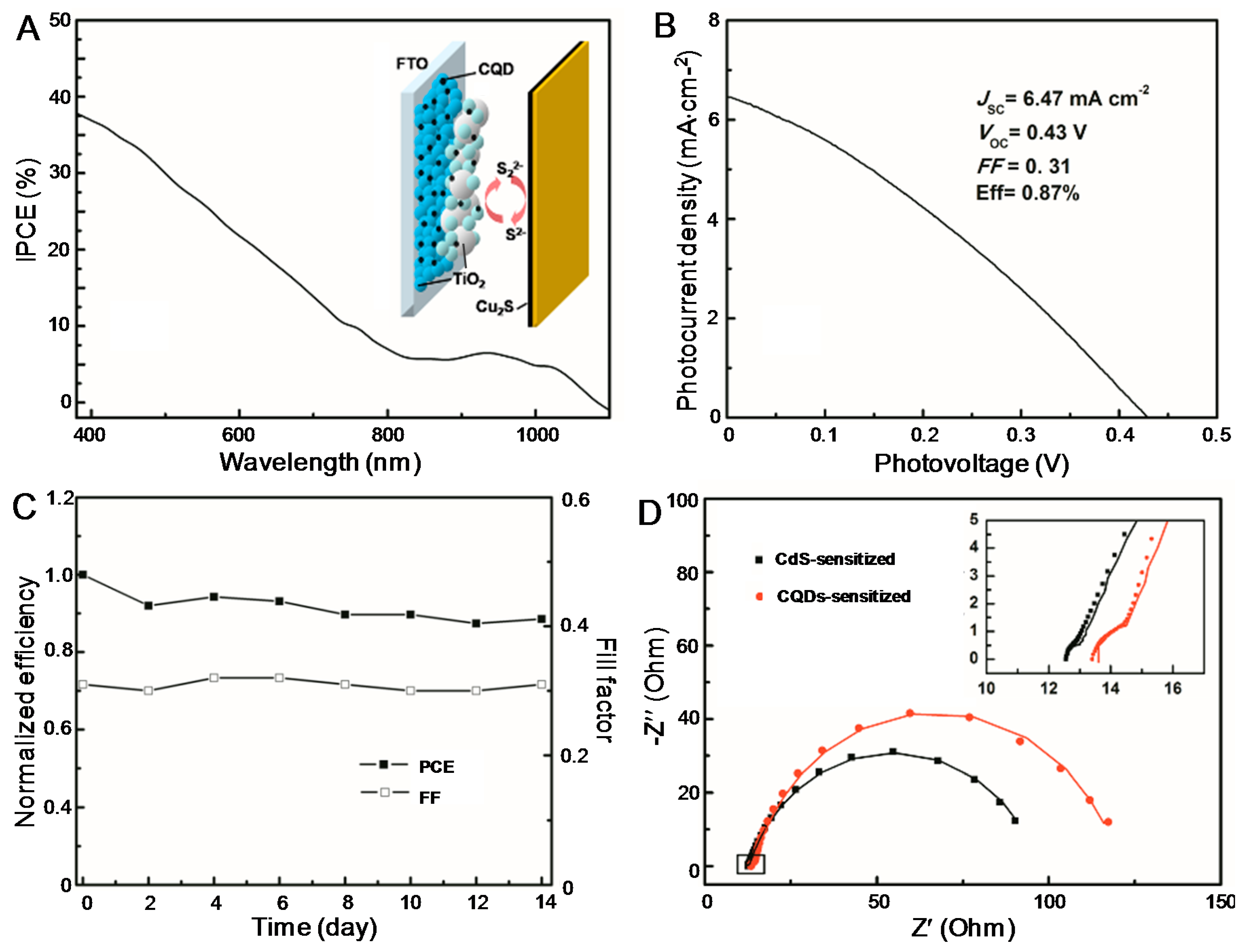
To construct the solar cell, Cu
2S on brass was selected as the counter electrode and polysulfide consisting of 1 mol·L
−1 Na
2S and 1 mol·L
−1 S in aqueous solution was used as the electrolyte. The selection of this cell structure is in favor of comparison with previously reported CdS-sensitized solar cells [
29] wherever necessary. An illustration of the cell structure is given in the inset of
Figure 3A. The IPCE spectrum shown in
Figure 3A matches the absorption spectrum of CQDs/TiO
2, indicating that the photocurrent was generated via the photoexcitation of CQDs. From the
JV curve, a
JSC of 6.47 mA·cm
−2, a
VOC of 0.43 V, and an
FF of 0.31 were obtained, which leads to a PCE of 0.87% (
Figure 3B). To the best of our knowledge, this PCE is the highest reported efficiency for solar cells sensitized by both CQDs and GQDs (
Table S1), which is mainly attributed to the impressively high
JSC. As the CQDs were grown in situ, the high
JSC could benefit from the improved contact between the CQDs and TiO
2. Investigations on parallel-prepared cells indicated that
JSC,
VOC, and PCE of the cells are reproducible with variations less than 8%. To test the long-term stability of the solar cell, it was stored at room temperature in the dark for up to 14 days. No significant decrease of both PCE and
FF could be observed (
Figure 3C), revealing the good stability of the cell.
We noticed that the
FF of our solar cell is lower than that of previously reported cells (
Table S1). As researchers tend to use different types of CQDs and the structure of the solar cells also varies, a strict comparison between different CQDSCs reported to date could be difficult. Previously, using the same cell structure, we have constructed a CdS-sensitized solar cell [
29], which is selected for comparison with the CQDSC reported in this work for further insight. The
JSC,
VOC,
FF, and PCE of the CdS-sensitized solar cell have been determined to be 6.57 mA·cm
−2, 0.435 V, 0.53, and 1.52%, respectively. Again, it is found that the
FF of the CQDSC is lower. It is known that the performance of the solar cell is heavily influenced by its internal charge transfer. To find out the reason for the relatively low
FF of the CQDSC, electrochemical impedance spectroscopy (EIS) measurements on the two cells sensitized by CQDs and CdS were carried out. In Nyquist plots, a dominant semicircle was observed in the mid and low frequencies together with a small one at high frequencies. We temporarily adopted the equivalent circuit developed previously [
29] to fit the data using Zview software, and fairly good fittings are obtained (the solid lines). It is known that the big semicircle reflects the charge transfer resistance and interfacial capacitance at the counter electrode/electrolyte interface, while the small one represents the charge recombination resistance and constant phase element at the photoanode/electrolyte interface. Compared to the CdS-sensitized solar cell, the CQD-sensitized cell suffers from a larger charge transfer resistance as evidenced from the much larger semicircle in the mid and low frequencies, which might account for its lower
FF and PCE. This conclusion is consistent with the remarks given in Margraf’s work, where the authors claimed that the balance between the charge recombination and regeneration processes is not ideal in CQDSCls [
23].
In ISQDSCs, it has been demonstrated that surface passivation of the photoanode by ZnS has a positive effect on the performance of the solar cells [
30]. When this method was applied to the CQDSCs presented in this work, however, decreased
JSC and
VOC values were observed, which results in a lower PCE of 0.64% (
Figure S1). The effects of photoanode annealing on the performance of the CQDSCs were also examined. Briefly, the CQDs-hybridized photoanode was heated in a muffle furnace under nitrogen for 10 min at 350 °C and 450 °C, respectively, followed by natural cooling to room temperature. After annealing, the absorption of the annealed photoanodes were enhanced, as confirmed by UV-vis-NIR measurements (
Figure S2). However, the decrease of
JSC and
VOC was noticed especially after annealing at 350 °C, which eventually led to a decreased PCE (see
Figure S3 for a detailed discussion of the effect of post-annealing). The failure of ZnS passivation and post-annealing in terms of further improving the performance of the CQDSCs indicates that the characteristics of this new type of solar cell are different from their counterparts based on ISQDs. This is understandable if one considers that the energy levels and/or charge transfer mechanisms behind CQDs and ISQDs are thought to be different [
31]. Although the outcome of ZnS passivation and post-annealing is somehow disappointing, it indicates that further optimization of CQDSCs should adopt a method that is thoroughly different from that well-established for ISQDSCs, which is important in terms of fundamental research.
3. Materials and Methods
3.1. Materials
Citric acid and ethanediamine were obtained from Sinopharm Chemical Reagent Co. Ltd. Terpineol, ethyl cellulose (EC), P25, 200-nm-sized anatase TiO2 nanoparticles were purchased from Jingge Solar Co. Ltd. (Wuhan, China). All chemicals were used without further purification. Solutions for electrolyte and QD deposition were prepared with high-purity water obtained from a water purification system (Ulupure Instrument Co. Ltd. Chengdu, China). The electrode substrate was fluorine-doped tin oxide conducting glass (FTO, thickness: 2.2 mm, Nippon, sheet resistance 14 Ω/square).
3.2. Preparation of TiO2-Coated Photoanode
Two kinds of TiO2 pastes adopted for doctor blading were prepared using P25 and 200 nm TiO2 particles, respectively. A transparent TiO2 layer was first coated on FTO glass using P25 paste, which was further grown by a scattering layer with a 200 nm TiO2 paste. After being leveled for 15 min, the samples were heated at 80 °C for 30 min and then annealed at 450 °C for 30 min. Finally, the samples were treated in a 40 mM TiCl4 solution, rinsed with water, dried under air flow, and heated to 500 °C in air for 30 min.
3.3. In Situ Growth of CQDs on TiO2 Surface
A TiO
2-coated photoanode is vertically immersed in the aqueous solution containing 0.5 mol·L
−1 citric acid and 0.5 mol·L
−1 ethanediamine. The system was then sealed in an autoclave at 180 °C and pyrolized for 24 h. The CQDs/TiO
2 hybridized photoanode was rinsed with deionized water thoroughly and dried in air. The CdS/TiO
2 hybridized photoanode was also prepared for comparison following the previous method (without annealing, photoanode 1 in Reference [
1]).
For passivation with ZnS, the CQD-sensitized photoanode was dipped into 100 mmol·L−1 Zn(CH3COO)2 aqueous solution followed by dipping in Na2S aqueous solution with the same concentration. This dipping circle was repeated twice with a duration of 1 min. To see the post-annealing influence on the performance of the solar cell, the CQD-sensitized photoanode was also sintered at 350 °C and 450 °C, respectively, in a muffle furnace under nitrogen for 10 min.
3.4. Construction of the Solar Cell
To construct the solar cell, polysulfide electrolyte was sandwiched between the CQD- or CdS-sensitized photoanode and the counter electrode separated with a silicone spacer. The electrolyte contains 1 mol·L−1 Na2S and 1 mol·L−1·s in ethanol/water mixture (3/7, v/v). Cu2S on copper was selected as a counter electrode based on the literature. The active area of the solar cell is ~0.20 cm2.
3.5. Characterizations
SEM observations were carried out on JSM-6700F. TEM observations were performed on JEOL JEM-100 CXII (JEOL Co. Ltd., Tokyo, Japan). Samples were prepared by scraping the photoanodes from the FTO substrate and dispersed in ethanol solution, followed by transferring several drops of the suspension onto a carbon-coated copper grid. XRD patterns were obtained between 10° and 80° in the 2θ scan mode using a Rigaku D/Max 2200-PC diffractometer with Cu Ka radiation (λ = 0.15418 nm) and a graphite monochromator (Rigaku Co. Ltd., Tokyo, Japan) at room temperature. Photoluminescence was recorded on a PerkinElmer LS-55 fluorescence spectrometer. FTIR spectra were obtained on a Bruker ALPHA-T IR spectrophotometer. The absorbance spectra were recorded by U-4100 UV-vis-NIR spectrophotometer (Hitachi Co. Ltd., Tokyo, Japan).
The solar cell (active area: 0.20 cm2) was prepared in a sandwich structure and its performance was evaluated by a source meter (Keithley 2400) illuminated with a SS150A solar simulator (Zolix Instrument Co. Ltd., Beijing, China) under AM 1.5 illumination of 100 mW·cm−2. Electrochemical impedance spectra (EIS) were recorded in the sandwich cell using a CHI 600E electrochemical analyzer (Chenhua, Shanghai, China) in the dark. The measured frequency for EIS ranged from 100 kHz to 100 mHz, and the amplitude was set to 10 mV. The results were fitted by Zview software. The incident-photon-to-current conversion efficiency (IPCE) was measured by the DC method using an Solar Cell Scan 100 (IPCE system, Zolix Instrument Co. Ltd., Beijing, China) without bias illumination.


