Article

Nanoparticulate Metal Oxide Top Electrode Interface Modification Improves the Thermal Stability of Inverted Perovskite Photovoltaics

by
Ioannis T. Papadas
1,
Fedros Galatopoulos
1,
Gerasimos S. Armatas
2,
Nir Tessler
3 and
Stelios A. Choulis
1,*
1
Molecular Electronics and Photonics Research Unit, Department of Mechanical Engineering and Materials Science and Engineering, Cyprus University of Technology, Limassol 3603, Cyprus
2
Department of Materials Science and Technology, University of Crete, 71003 Heraklion, Greece
3
Sara and Moshe Zisapel Nano-Electronic Center, Department of Electrical Engineering, Technion-Israel Institute of Technology, Haifa 32000, Israel
*
Author to whom correspondence should be addressed.
Nanomaterials 2019, 9(11), 1616; https://doi.org/10.3390/nano9111616
Submission received: 15 October 2019 / Revised: 4 November 2019 / Accepted: 11 November 2019 / Published: 14 November 2019

Abstract

:
Solution processed γ-Fe2O3 nanoparticles via the solvothermal colloidal synthesis in conjunction with ligand-exchange method are used for interface modification of the top electrode in inverted perovskite solar cells. In comparison to more conventional top electrodes such as PC(70)BM/Al and PC(70)BM/AZO/Al, we show that incorporation of a γ-Fe2O3 provides an alternative solution processed top electrode (PC(70)BM/γ-Fe2O3/Al) that not only results in comparable power conversion efficiencies but also improved thermal stability of inverted perovskite photovoltaics. The origin of improved stability of inverted perovskite solar cells incorporating PC(70)BM/ γ-Fe2O3/Al under accelerated heat lifetime conditions is attributed to the acidic surface nature of γ-Fe2O3 and reduced charge trapped density within PC(70)BM/ γ-Fe2O3/Al top electrode interfaces.

Graphical Abstract

1. Introduction

Over the last couple of years, perovskite solar cells proved to be a strong candidate for photovoltaic (PV) technologies while showing a considerable improvement in power conversion efficiency (PCE) from 3.8% to 22.7% [1,2]. The attractiveness of perovskite solar cells as a novel research field is a result of several features such as high carrier mobility [3], long carrier diffusion length [4], high absorption coefficient [5], tunable bandgap [6,7], and low exciton binding energy [8,9]. These characteristics allow perovskite solar cells to achieve high PCE while being compatible with solution processed fabrication techniques at low temperatures [10]. When considering the viability of any novel PV technology for competing in the silicon dominated industry, achieving high PCE is not enough. Ensuring long term stability is also equally important. Even though perovskite solar cells have achieved promising PCEs, poor stability often hinders this PV technology to reach its full potential. Perovskite-based solar cells still struggle to achieve good lifetime performance under moisture, heat and light soaking conditions. For instance, the perovskite crystal can decompose in the presence of water molecules into PbI2 through mobilization of the organic species [11,12,13]. In order to improve the humidity stability of PSCs several methods were reported, such as the usage of hydrophobic thiols [11]. In one of the most recent reports, Fan et. al. utilized a cerium oxide bilayer (CeOx) to achieve a 200-h lifetime under ambient conditions [14]. The perovskite crystal also shows poor intrinsic stability in the presence of O2 under illumination. In such a case, superoxide ions (O2) can be formed upon irradiation of CH3NH3X3 (X = Cl, Br, I halides) which causes the decomposition of the perovskite crystal structure via the deprotonation of methylammonium cation (MA+) [13,15]. Improvements in the light stability of perovskite-based solar cells have been reported from several research groups by doping the [6,6]-phenyl-butyric acid methyl ester (PCBM) with graphene quantum dots (GQDs) [16] or by adopting devices based on mixed cations, such as formamidinium-cesium [FA0.83Cs0.17Pb(I0.8Br0.2)3] [17]. As previously mentioned, another important parameter that can affect the stability of perovskite-based solar cells is heat. The perovskite crystal was reported to decompose when exposed to oxygen atmospheres in conjunction with an elevated temperature of 85 °C [18]. To this end, several approaches have been suggested in order to improve the heat stability of perovskite-based solar cells. These include using thermally stable nickel oxide (NiO) and PCBM as the hole transporting layer (HTL) and electron transporting layer (ETL), respectively [19], or even using a thin Cr layer between the HTL and active layer to block the diffusion of Au into the active layer, which was shown to take place even at temperatures as low as 70 °C [20].
Amongst the different buffer layers that have been used, both for improving the PCE and stability of PSCs, metal oxides have been a relatively popular choice [21]. Al-doped zinc oxide (AZO) has been shown to act as an efficient ETL for perovskite-based solar cells [6], whereas incorporations of tin oxide (SnOx) on top of AZO has also been reported proven to improve both humidity and heat stability of p-i-n structure perovskite-based devices [22]. Recent publications have also incorporated delafossites, such as CuGaO2 [23], and spinel structure oxides, such as NiCo2O4 [24], as efficient HTLs.
Iron(III) oxide (Fe2O3) has recently become a very attractive material for environmental applications, due to its high chemical stability, low cost, abundance, non-toxicity and magnetic separation ability [25,26]. Examples include photocatalysis, adsorption, reduction, water splitting and organic synthesis area [27,28,29,30,31,32,33,34]. Recently, Fe2O3 is explored as a potential photoanode material in visible-light-driven water splitting due to its visible light response (bandgap energy ~2–2.2 eV) and appropriate valence band (Ev) position (~2.5 V vs. NHE at pH = 1) [35]. There are continuous efforts towards the synthesis of well-defined Fe2O3 nanostructures. A large variety of Fe2O3 nanoparticles (NPs) with fine control over the size (from 2 to 100 nm) and shape (from cubic, to spherical and to nanosheets) have been successfully implemented [36]. Unfortunately, the implementation of such nanomaterials, especially in planar perovskite solar cells, is hobbled by their strong tendency to form large agglomerates in solution. In addition, the morphology of the obtained segregated assemblies is irregular, and thus new strategies to access stable monodispersed solutions of NPs and their usage in solution processed techniques for the fabrication of low-cost hybrid perovskite solar cells are indispensable. Fe2O3 has been previously used in normal n-i-p structured perovskite solar cells for replacing the more conventional titanium dioxide (TiO2), showing improved PCE [37]. A similar approach utilized Fe2O3 nano islands to enhance the photostability of n-i-p perovskite solar cells by replacing the TiO2 [38]. The synergistic effect of fullerene/Fe2O3 was also explored as ETL, which resulted in improved PCE and ambient stability of devices by improving the crystallinity of the perovskite layer [39]. Although Fe2O3 has been a very common and popular metal oxide, it is relatively unexplored as an interfacial layer in the field of inverted perovskite solar cells.
In this work, we report improved thermal stability for inverted (p-i-n) perovskite-based solar cells using colloidal synthesized nanoparticulate γ-Fe2O3 interfacial modification. By incorporating a thin (~15 ± 5 nm) γ-Fe2O3 interfacial layer between PC(70)BM and Al we report improved lifetime performance under accelerated heat conditions (60 °C) and N2 atmosphere for inverted perovskite-based solar cells. Using frequency-dependent impedance spectroscopy we show that the top electrode γ-Fe2O3 based interface modification improved heat stability due to the reduced charge trap density, as evident by the insensitivity of Vbi to frequency changes.Subsequently, a more intimate interface is formed between the γ-Fe2O3 ETL and the top metal electrode compared to inverted perovskite solar cells using more conventional ETLs such as plain PC(70)BM and aluminum-doped zinc oxide (AZO) under identical (accelerated heat lifetime) conditions. In contract to AZO, the surface properties of γ-Fe2O3 appear to be beneficial for the protection of perovskite active layer from the deprotonation of the methylamine. The experimental results presented highlight the potential of the proposed γ-Fe2O3 as an effective interface modification for inverted perovskite-based solar cells.

2. Experimental Section

2.1. Materials

Chemical reagents: Iron (III) chloride hexahydrate (FeCl3.6H2O, ≥97%), Oleylamine (85%), Sodium oleate (80%), Oleyl alcohol, (85%), diphenyl ether (99%), N,N-dimethylformamide (DMF, 99.9%), acetone, acetonitrile (99.9%), hexane (95%), toluene (99.7%) and absolute ethanol (98%) were purchased from Sigma-Aldrich Chemical (Darmstadt, Germany) Co. Nitrosonium tetrafluoroborate (NOBF4, 97%) was purchased from Acros Organics (San Mateo, CA, USA). Ultrapure water was produced by a milli-Q Academic system, Millipore (Burlington, MA, USA). All solutions were prepared with analytical grade chemicals and ultrapure milli-Q water with a conductivity of 18.2 μS cm−1.

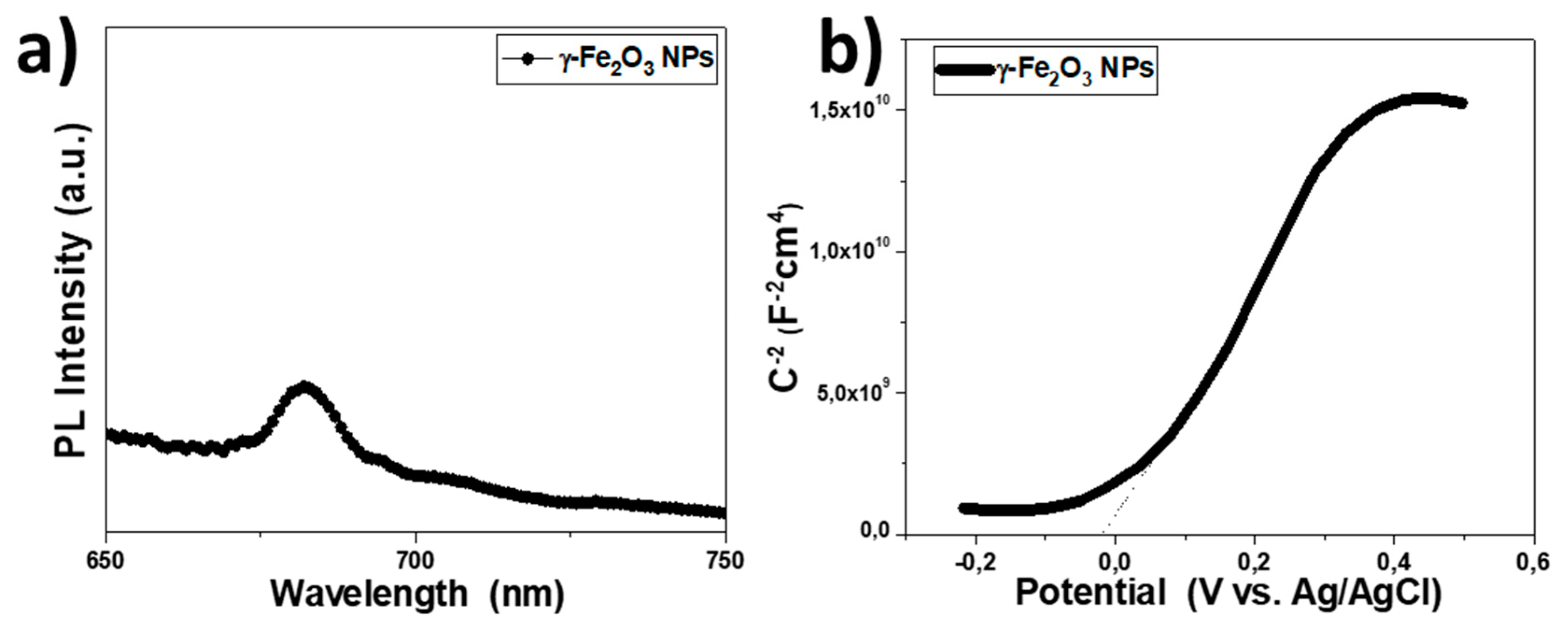
2.2. Synthesis of γ-Fe2O3 NPs

Iron oxide NPs with an average diameter of ~5 nm was prepared according to the previously reported procedure [28], with slight modifications highlighted below. Briefly, FeCl3.6H2O (5.4 g, 20 mmol) and sodium oleate (18.25 g, 60 mmol) were added to a mixture of ethanol (40 mL), deionized water (30 mL), and hexane (70 mL). The mixture was refluxed at 70 °C for 4 h, then the upper brown hexane solution containing iron–oleate complex was separated, washed three times with deionized water (50 mL), and dried under vacuum at 60 °C for 12 h, yielding a dark brown, oily iron oleate complex. Finally, the iron oleate complex (10.8 g) was dissolved in 60 g of diphenyl ether with the addition of oleyl alcohol (19.4 g). Under N2 flux, this mixture under stirring was heated to 105 °C at a ramp rate of 2 °C min−1 and kept for 10 min at this temperature to eliminate H2O and adsorbed O2 [28]. For the work reported in this paper the mixture was heated to 220 °C at a ramp rate of 2 °C min−1 and the reaction could proceed for 20 min at this temperature. The resulting black brown nanocrystal solution was left to cool at room temperature. Then, the γ-Fe2O3 NPs were precipitated with 50 mL acetone followed by centrifugation at 14.500 rpm for 20 min and re-dispersed in hexane to form a stable colloidal solution (10 mg mL−1).

2.3. Preparation of Ligand-Stripped γ-Fe2O3 NPs

The surface of γ-Fe2O3 NPs was modified with NOBF4 using a ligand-exchange reaction. Briefly, equal volumes (5 mL) of colloidal γ-Fe2O3 NPs in hexane and 0.01 M NOBF4 in acetonitrile were mixed and the resulting mixture was kept under stirring at room temperature until the NPs were transferred to the acetonitrile phase (typically within ~1 h). The BF4 capped Fe2O3 NPs were then collected by precipitation with toluene followed by centrifugation, dried under vacuum at 40 °C for 12 h, and dispersed in ethanol to form a stable colloidal solution (5 mg mL−1).

2.4. Device Fabrication

The inverted (p-i-n) solar cells under study had the structures ITO/PEDOT:PSS/CH3NH3PbI3/PC70BM/Al, ITO/PEDOT:PSS/CH3NH3PbI3/PC70BM/AZO/Al and ITO/PEDOT:PSS/CH3NH3PbI3/PC70BM/γ-Fe2O3/Al, respectively. ITO-patterned glass substrates (sheet resistance = 4 Ω sq−1) were cleaned using an ultrasonic bath for 10 min in acetone followed by 10 min in isopropanol. The PEDOT:PSS films were prepared using the Al4083 solution from Heraeus. PEDOT:PSS was filtered using 0.22 μm polyvinylidene difluoride (PVDF) filters before coating. The PEDOT:PSS films were coated using spin-coating at 6000 rpm for 30 s followed by annealing at 150 °C for 10 min. The perovskite solution was prepared using a mixture (1:1) of PbI2 from Alfa Aesar and MAI from GreatCell Solar. The mixture was dissolved in a solvent (7:3) of γ-butyrolactone and dimethyl sulfoxide (DMSO). The solution was stirred at 60 °C for 1 h. The perovskite solution was left to cool at room temperature inside the glove box followed by filtering using a 0.22 μm PVDF filter. The perovskite films were coated using a three-step spin-coating process: first step 500 rpm for 5 s, second step 1000 rpm for 45 s, and third step 5000 rpm for 45 s. During the third step, after the first 20 s of the duration of the step, 0.5 mL toluene was dropped onto the spinning substrate to achieve the rapid crystallization of the films. The resulting perovskite films were annealed at 100 °C for 10 min. The PC(70)BM film was then coated using a solution of 20 mg mL−1 in chlorobenzene to achieve fullerene thickness of 70 nm, at 1000 rpm for 30 s. The AZO solution used was a commercial solution (N-20X) from Avantama Ltd. AZO films were coated using spin-coating at 3.000 rpm for 30 s. To form a 15 ± 5 nm electron transporting layer (ETL) of γ-Fe2O3, the γ-Fe2O3 NPs dispersion (5 mg L−1 in ethanol) used in this study was dynamically spin-coated at 3000 rpm for 30 s on top of the PC(70)BM films. The thicknesses of the device layers were accurately measured with profilometer. The Al metal was finally thermally evaporated achieving a thickness of 100 nm. The devices were encapsulated directly after the evaporation of the metal contact, in the glove box using a glass coverslip and an encapsulation epoxy resin (Ossila E131) activated by 365 nm UV-irradiation.

2.5. Characterization

The thicknesses and the surface profile of the device layers were measured with a Veeco Dektak 150 profilometer (Hong Kong, China). Wide-angle XRD patterns were collected on a PANanalytical X’pert Pro MPD X-ray diffractometer (Malvern, UK) equipped with a Cu (λ = 1.5418 Å) rotating anode operated at 40 mA and 45 kV, in the Bragg-Brentano geometry. The current density-voltage (J/V) characteristics were characterized by a Botest LIV Functionality Test System (Kreuzwertheim, Germany). Both forward (short circuit open circuit) and reverse (open circuit short circuit) scans were measured with 10 mV voltage steps and 40 ms of delay time. For illumination, a calibrated Newport Solar simulator (Irvine, CA, USA) equipped with a Xe lamp was used, providing an AM1.5G spectrum at 100 mWcm−2 as measured by a certified oriel 91,150 V calibration cell. A custom-made shadow mask was attached to each device prior to measurements to accurately define the corresponding device area. EQE measurements were performed by Newport System (Irvine, CA, USA), Model 70356_70316NS. Impedance spectroscopy was performed using a Metrohm Autolab PGSTAT 302N equipped with FRA32M module (Herisau, Switzerland). To extract the Nyquist plots, the devices were illuminated using a red LED at 625 nm and 100 mw/cm2. A small AC perturbation voltage of 10 mV was applied, and the current output was measured using a frequency range of 1 MHz to 1 Hz. The steady-state DC bias was kept at 0 V. Mott-Schottky measurements on γ-Fe2O3 films were performed in a 0.5 M Na2SO4 aqueous electrolyte (pH = 7) using a Metrohm Autolab PGSTAT 302N potentiostat. A three-electrode set-up, with a platinum plate (1.0 × 2.0 cm2) and a silver-silver chloride (Ag/AgCl, 3M KCl) as the counter and reference electrodes, respectively, was adopted to study the samples. The capacitance of the semiconductor/electrolyte interface was obtained at 1 kHz, with 10 mV AC voltage perturbation. All the experiments were conducted under dark conditions. The measured potential vs the Ag/AgCl reference electrode was converted to the normal hydrogen electrode (NHE) scale using the formula: ENHE = EAg/AgCl + 0.210 V. The working electrode for impedance-potential measurement was fabricated as follows: ~10 mg of γ-Fe2O3 NPs was dispersed in 1 mL DI water and the mixture was subjected to sonication in a water bath until a uniform suspension was formed. After that, 100 µL of the suspension was drop-casted onto the surface of fluorine-doped tin oxide (FTO, 9 Ω/sq) substrate, which was masked with an epoxy resin to expose an effective area of 1.0 × 1.0 cm2. The sample was dried in a 60 °C oven for 30 min. Photoluminescence (PL) spectrum was obtained at room temperature on a Jobin-Yvon Horiba FluoroMax-P (SPEX) spectrofluorimeter (Singapore) equipped with a 150 W Xenon lamp and operated from 300 to 900 nm The C–V measurements for the Mott–Schottky plots for full devices were performed under dark using a voltage range of −1 to 1 V at a constant frequency of f = 5 kHz. Transmittance and absorption measurements were performed with a Shimadzu UV-2700 UV–vis spectrophotometer (Kyoto, Japan). Diffuse reflectance UV–vis spectra were recorded at room temperature with a Shimadzu UV-2700 UV-Vis optical spectrophotometer, using powder BaSO4 as a 100% reflectance standard. Reflectance data were converted to absorption (α/S) data according to the Kubelka-Munk equation: α/S = (1 − R)2/(2R) [40], where R is the reflectance and α, S are the absorption and scattering coefficients, respectively. Atomic force microscopy (AFM) images were obtained using a Nanosurf easy scan 2 controllers in tapping mode. Transmission electron microscopy (TEM) images were taken with a JEOL Model JEM-2100 electron microscope operating at 200 kV accelerated voltage. Samples for TEM analysis were prepared by drying an ethanolic dispersion of the particles on a holey carbon-coated Cu grid.

3. Results and Discussion

3.1. γ-Fe2O3 Interface Modification for Inverted Perovskite Solar Cells

In this work, we have used solvothermal colloidal synthesis in conjunction with the ligand-exchange method to isolate uniform γ-Fe2O3 NPs, well-dispersed in polar solvents. In particular, we utilized nitrosonium tetrafluoroborate (NOBF4) to exchange the native ligands (oleyl alcohol) on the surface of γ-Fe2O3 NPs and charge stabilized them by BF4 anions as shown in Figure 1 [41]. The advantage of using ligand-stripped NPs is that their surface OH groups may provide high solubility in polar solvents while ensuring close proximity between them during drying process. A well-connected NP network is achieved using this method. The BF4-capped γ-Fe2O3 NPs can be readily dispersed in various polar solvents, such as N, N-dimethylformamide (DMF), acetonitrile and ethanol, producing stable colloidal solutions even for several months as shown in Figure S1. Using the spin coating technique, the bare γ-Fe2O3 NPs can then be self-assembled into 2D arrays of closely packed NPs with conductive bridges between them and low surface roughness, attributes that are crucial for planar p-i-n perovskite solar cells (PVSCs) applications.
The crystal structure and morphology of the as-prepared γ-Fe2O3 NPs were characterized by X-ray diffraction (XRD) and transmission electron microscopy (TEM). The XRD pattern in Figure 2c demonstrates the formation of a cubic spinel-type structure with P4132 space group symmetry (JCPDS No. 39-1356). It is worth noting that within the XRD detection limits (~3–5 wt%) no impurity crystal phases were detected (e.g., α-Fe2O3 and spinel Fe3O4 phase), indicating that the obtained NPs are single-phase γ-Fe2O3. Using the (311) peak width of the diffraction pattern and the Scherrer equation, we calculated the average crystalline size of ~5.5 nm. Figure 2a displays a typical TEM image for the γ-Fe2O3 NPs sample. The image shows spherical-shaped NPs with diameter of ~5 nm, which is consistent with the γ-Fe2O3 grain size obtained from XRD analysis. The crystal structure of the NPs was further examined by selected-area electron diffraction (SAED). Consistent with XRD studies, the SAED pattern of the γ-Fe2O3 NPs sample revealed its pure phase and high crystallinity. All the Debye-Scherrer diffraction rings can be indexed to the cubic, closely packed structure of γ-Fe2O3 (Figure 2b). To investigate the optical properties of the as-prepared γ-Fe2O3 NPs, we utilized diffuse reflectance ultraviolet-visible/near-IR (UV-vis/NIR) spectroscopy. The UV-vis/NIR spectrum shows an intense optical absorption onset in the visible region, which is associated with an optical band gap of 1.9 eV, as estimated from the Tauc plot for direct interband transitions (Figure 2d).
Thin films of γ-Fe2O3 NPs were spin-casted next on top of PC(70)BM and quartz substrates using the spin coating technique, applying the processing parameters as described in the Experimental Section. Figures S2 and S3 display the surface topography of a 15 ± 5 nm thick film of γ-Fe2O3 NPs fabricated on top of PC(70)BM and quartz substrates, respectively, as obtained by AFM line scans. On top of PC(70)BM the surface roughness is ~5 nm, which is comparable with the roughness obtained by plain PC(70)BM as well as PC(70)BM/AZO films. The γ-Fe2O3 film fabricated on quartz substrate exhibits a smooth and compact topography of only ~4.3 nm roughness. It should be noted that the development of a low roughness layer is beneficial for the photovoltaic perovskite solar cells (PVSCs) performance. Figure S4 shows the transparency of the AZO and γ-Fe2O3 layers, respectively. As shown in Figure S4, AZO layer presents high transparency in the visible region, while a slightly lower transmittance is observed for γ-Fe2O3 layer.
Photoluminescence (PL) was performed at 550 nm excitation wavelength, to investigate the electronic band structure and charge transfer properties of γ-Fe2O3 NPs, as shown in Figure 3a. In the case of pure defect-free crystals, we can expect only the band edge emission in the PL spectra. However, the PL spectrum of γ-Fe2O3 NPs exhibits a weak peak at ~680 nm, which is a higher wavelength than band edge emission This is ascribed to defect levels in the forbidden energy gap of the nanocrystals. Electrochemical impedance spectroscopy (EIS) was then used to investigate the energy levels of γ-Fe2O3. The resulting Mott-Schottky plot and the corresponding fit of the linear portion of the inverse square space-charge capacitance (1/Csc2) as a function of potential (E) for γ-Fe2O3 NPs are shown in Figure 3b. It is apparent that the γ-Fe2O3 shows a positive linear slope, indicating n-type conductivity, where electrons are the majority carriers. Using extrapolation to 1/CSC2 = 0, the flat-band potential (EFB) calculated for γ-Fe2O3 NPs was 0.19 eV vs. NHE (pH = 7). Based on the EFB value and optical band gap (as obtained from UV–vis/NIR reflectance data, Figure 2d), the energy band edges for Fe2O3 are CB: −4.28 eV and VB: −6.18 eV vs vacuum, respectively (Figure 4b). For heavily n-type doped semiconductors such as γ-Fe2O3, it is quite reasonable to assume that the EFB level lies very close to the CB edge. Typically, for many n-type semiconductors, the CB edge is about 0.1–0.3 eV higher than the EFB potential. Thus, the position of the valence band (VB) edge was estimated from EFB–Eg.

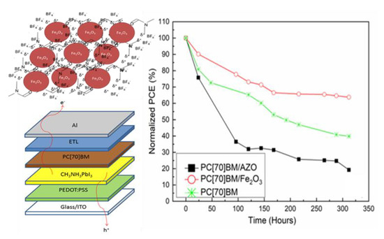
3.2. Inverted Perovskite Solar Cells Heat Accelerated Lifetime Studies

In order to test the effectiveness of γ-Fe2O3 nanoparticulate ETL for inverted structured PVSCs, completed devices were fabricated based on the general inverted device structure ITO/PEDOT:PSS (~30 nm)/CH3NH3PbI3 (~300 nm)/ETL/Al (~100 nm), where the three different ETLs under investigation were compared: PC(70)BM (~70 nm), PC(70)BM/AZO (~40 nm) and PC(70)BM/Fe2O3 (15 ± 5 nm). A schematic representation of the device structure is shown in Figure 4a. The exact fabrication steps and materials used are described in detail in the Experimental Section. The use of γ-Fe2O3 in conjunction with PC(70)BM was found to have little impact on the PCE of p-i-n structured devices since the PCEs were comparable both to PC(70)BM as well as PC(70)BM/AZO. This is further highlighted in the energy level diagram shown in Figure 4b, which is based on measured values of γ-Fe2O3 with EIS and the literature respectively [39,42]. The representative values of PV parameters from a total of 10 devices from each structure, that described in detail above, are summarized in Table 1.
As we have previously noted, by using PC(70)BM/γ-Fe2O3 as electron selective contact instead of plain PC(70)BM or PC(70)BM/AZO appears to have no significant effect to the device PCE (only a slight drop in FF, from 75 to 70%, was observed). It is important to note that the focus of this work was to inspect the effect of γ-Fe2O3 as a solution processed interface modification for improving the stability of the inverted PVSCs. For the same reasoning we chose to use widely used and understood materials such as PEDOT: PSS as the HTL and a basic perovskite CH3NH3PbI3 formulation as the active layer for the inverted PVSCs. The device structure and perovskite formulation used within this work offer high reliability and reproducibility, essential parameters for fabricated devices in lifetime studies. The experimental results presented were consistent on several experimental runs
We have recently reported that in inverted PVSCs using PEDOT: PSS HTL, the main heat degradation pathway is the interaction of Al top metal contact with the perovskite active layer through diffusion mechanisms. We have incorporated a thick PC(70)BM (200 nm) diffusion blocking layer to improve stability. However, in some cases incorporation of thick buffer layers, has a significant negative impact on the inverted PVSCs PCE [43]. In this work, we investigate the effect of using a thin (15 ± 5 nm) γ-F2O3 based interfacial layer on the heat accelerated lifetime performance of inverted PVSCs. The accelerated heat lifetime performance of inverted PVSCs incorporating γ-Fe2O3 within the top electrode (PC(70)BM/Fe2O3/Al) has been compared with the more conventional PC(70)BM/Al and PC(70)BM/AZO/Al inverted PVSCs top electrodes. The conditions for the lifetime experiments were 60 °C and N2 atmosphere under dark for all PVSCs presented within the paper. The normalized lifetime was plotted from the average PV parameters of 10 devices for each architecture and the results which are listed in Figure 5 were consistent on several lifetime runs for the conditions described within this work.
From the lifetime plots, there are some considerable differences between the behavior of the three different (top electrode) inverted PVSCs device architectures. The PV parameters of the PVSCs incorporating γ-Fe2O3 within the top electrode (PC(70)BM/γ-Fe2O3/Al) show considerable improvement in stability compared to devices based on PC(70)BM/Al and PC(70)BM/AZO/Al top electrode. Specifically, PC(70)BM/Fe2O3/Al based devices have T80 (the time the PCE reached 80% of its initial fabrication value) at 100 h of operation and has even retained 70% of their PCE after 300 h of testing, whereas devices with PC(70)BM/Al have T80 at 24 h and the PCE settled at the lowest value of 40% of their original PCE when the aging test has reached 300 h. The devices with PC(70)BM/AZO/Al have dropped to 70% at the first 24 h of aging, reaching below 40% at the 100 h mark and have settled even lower at 15% when the aging test has reached the 300 h. Figure 5 shows that Jsc in the PC(70)BM/AZO/Al-based inverted PVSCs shown the strongest drop under the heat accelerated lifetime condition presented within this paper.

3.3. Device Performance Analysis and Degradation Mechanisms

Complementary to the heat accelerated lifetime test, we have carried out characterization studies on representative devices for the three device architectures at the 168 h mark. We have chosen this point for characterization since it lies in the middle of the aging test and thus it would ensure that the devices showed significant differences between them while still being eligible for testing and are not completely degraded from the aging test. In particular, the devices were characterized using illuminated and dark J-V measurements as well as Mott-Schottky analysis (discussed in detail within the next section).
Figure 6a depicts the illuminated J-V characteristic for the three device architectures. The Voc change with respect to aging is very clearly observed. In particular, the device based on PC(70)BM/AZO/Al shows a very sharp drop to Voc, indicated by the shift of the J-V curve to the left. There is also a very significant sign of hysteresis in this device which could be attributed to charge traps or ion migration manifesting through the aging test [44]. Both inverted PVSCs architectures using PC(70)BM/Al and PC(70)BM/Fe2O3/Al show negligible signs of hysteresis. However, the devices without γ-Fe2O3 interface modification (PC(70)BM/Al) show a significant drop to Voc (although not as severe as in PC(70)BM/AZO/Al-based inverted PVSCs), while inverted PVSCs using PC(70)BM/Fe2O3/Al provide clearly more stable Voc values under heat accelerated lifetime conditions. Dark J-V plots are shown in Figure 6b. From the dark JV plots the series resistance (Rs and Shunt resistance (Rsh) were estimated (Table 2). The devices with PC(70)BM/AZO/Al top electrode show significantly reduced Rsh from 36.26 to 5.56 kΩ and increased leakage current after aging compared to the other two top electrode architectures under investigation. Furthermore, the diode characteristic is completely lost in devices with PC(70)BM/AZO/Al top electrode. In comparison, the device with PC(70)BM/Al has also shown a decrease to Rsh from 37.04 to 11.24 kΩ and increase in leakage current which is not as severe as the PC(70)BM/AZO/Al-based inverted PVSCs. Importantly, the inverted PVSCs with PC(70)BM/Fe2O3/Al top electrodes show almost no change after aging regarding Rsh and leakage current (a parameter which is shown the quality of the inverted PVSCs incorporating the proposed γ-Fe2O3 interface modification). Both devices with PC(70)BM and PC(70)BM/Fe2O3 ETLs seem to retain the diode characteristic after aging. This trend follows the observation of Voc drop, where devices with decreased Rsh and increased leakage current also show a proportional drop to their Voc.
Following the observations from our previous work based on absorption spectra and XRD measurements [43], as well as other reports in the literature [18], the MAPI perovskite active layer was not identified as the major degradation pathway for inverted perovskite solar cells under accelerated heat lifetime conditions [43]. The two main mechanisms that could be related to the degradation of the devices are (i) diffusion of halide ions to the metal electrode and (ii) diffusion of metal atoms to the CH3NH3PbI3. Both these mechanisms were observed by Fang et al. where diffusion of I towards the Ag electrode, as well as migration of Ag into CH3NH3PbI3 under ambient humidity and light soaking for 200 h [14]. In particular, diffusion of I ions are common in such devices due to the small activation energy (~0.29 eV), high concentration gradient (1015 cm−4) and fast diffusion coefficient (3.1 × 10⁻⁹ cm2s−1) [45] which is further accelerated at higher temperatures [46]. Metal ions also exhibited diffusion towards the perovskite under accelerated heat conditions. It was recently reported that upon heating at 70 °C, Au atoms can travel through spiro-MeOTAD HTL and migrate towards the perovskite layer, negatively affecting the overall device performance. [19] In previous works buffer layers such as Cr2O3/Cr [47] and SnOx [22] were used in conjunction with PCBM to reduce the degradation by blocking the aforementioned diffusive degradation products of inverted PVSCs under accelerated heat conditions and constant light illumination.
Another major concern that has been recently placed is the negative effect that doping can have on the stability of PSCs. Recently a comprehensive study was performed by N. Tessler and Y. Vaynzof using a model solar cell system based on electron-ion conducting perovskite active layer. In that work it was shown that undoped charge selective layers (CSLs) can be used to significantly decrease the voltage drop across the perovskite active layer and therefore suppress the ion accumulation through the device, preventing hysteresis and degradation of perovskite solar cells [48]. On contrary using doped CSLs the potential drop across the perovskite active layer was reported to be significantly larger compared to undoped CSLs and therefore the suppression of ion accumulation is expected to be less efficient [48]. Although in our case we compare two ETLs that one is doped (AZO) and another that is undoped (Fe2O3), it is worth mentioning the role of the PC(70)BM passivation/buffer layer that lies between the AZO and the perovskite active layer. Since The PC(70)BM layer is inherently undoped, ionic accumulation issues from doping related to AZO should not be dominant [48]. The fact that devices with AZO have shown the worst stability led us to search for a different explanation. The instability of AZO in p-i-n PSCs has also been previously reported by K. Brinkmann et al. [22]. It is reported in several works that zinc oxide (ZnO) can negatively impact the stability of CH3NH3PbI3 upon annealing through the deprotonation of MA+ caused by residual OH on the ZnO nanoparticles surface that are often present. It was also reported that PCBM as a buffer layer can reduce, but not completely avoid this decomposition [21,49]. This correlates with our observation from the lifetime plots in Figure 5b, showing a strong reduction in Jsc values for devices with AZO, pointing towards the degradation of the PVSK active layer whereas both PC(70)BM and PC(70)BM/γ-Fe2O3 show negligible drop to Jsc.
A crucial factor for the stability and the quality of halide perovskite crystallization is the acidic or basic character of the metal oxides, which are used as HTLs or ETLs in the perovskite solar cells (PVSCs). The acidic or basic nature of metal oxides depends on the corresponding isoelectric point (IEP). It has been observed that these hydroxyl groups on the interfaces of metal oxides with basic nature cause decomposition of the hybrid halide perovskite through the deprotonation of the methylamine, leading to PbI2. This decomposition mechanism is not observed in more acidic metal oxides (such as TiO2 and ITO) [50]. In the literature, γ-Fe2O3 NPs interfaces are typically acidic (with isoelectric points in the range of 5.5−6.7) [51], whereas ZnO NPs interfaces tend to be more basic (with isoelectric points >8.7) [52]. This suggests that the deprotonation of the MA+ (pKa of ~10.6) by the ZnO surface may be a possible cause of the thermal decomposition [53]. Since ZnO is the main component of AZO, the experimental results presented within this paper indicate that in contrast to the basic nature of aluminum-doped ZnO (AZO), the more acidic surface of γ-Fe2O3 assist on preventing negative chemical interactions with the perovskite active layer resulting to inverted perovskite solar cells with improved Jsc stability under heat accelerated lifetime studies. Furthermore, by the incorporation of γ-Fe2O3 interfacial layer on top of PC(70)BM any surface defects of inconsistent film coverage from the PC(70)BM film can be passivated by the γ-Fe2O3 interfacial layer improving the stability of the inverted perovskite photovoltaics devices under accelerated heat lifetime conditions.

3.4. Impedance Spectroscopy Device Characterization and the Effect of Interfacial Trap States

Using Mott-Schottky analysis we have tried to understand why the incorporation of γ-Fe2O3 interfacial layer within the top electrode (PC(70)BM/γ-Fe2O3 /Al) has resulted in better stability compared to more conventional top electrodes such as PC(70)BM/Al and PC(70)BM/AZO/Al. Capacitance voltage (CV) techniques are useful characterization tools that can help distinguish processes that manifest in the active layer from the ones in the contacts. At reverse bias full depletion occurs and the capacitance corresponds to the geometric capacitance (Cg) determined by the dielectric constant of the perovskite [47]. The point of intersection with the x-axis denotes the extracted built-in voltage (EVbi) value which depends on the energy equilibration at the contacts. Mott Schottky plots are based on the depletion approximation, where we consider that the capacitance in the space charge region is purely due to doping and there are no free charges. It is interesting to note that in general this approximation doesn’t hold true close to the metal contacts where charges tend to accumulate, thus the value of EVbi calculated from the Mott-Schottky analysis is not the true value of Vbi, but can still be used for comparative studies [47]. Mott-Schottky analysis has been previously utilized for the quantification of charge traps in PSCs by studying the response of charged carriers to the AC signal that is applied in the CV measurement. When using relatively high frequencies (HF) at ~100 kHz only free charges at the conduction band (Ec) can follow the AC voltage perturbation applied in CV measurements and can contribute to the EVbi value. When the frequency is dropped to low frequencies (LF) at ~500 Hz we are effectively approaching DC conditions, where de-trapping of charges can occur and therefore contribute to EVbi and as a result of Voc [54]. Therefore, the presence of trapped charges can contribute to the overall EVbi value, effectively altering it, depending on the frequency used for the Mott-Schottky analysis [55]. Using this information we have performed a comparative study where the EVbi change between HF and LF was correlated with the population of traps inside freshly prepared devices.
From Figure 7a,b we have used linear interpolation to extract the value of EVbi from the point of intercept of the linear part in the Mott-Schottky plot with the x-axis. Some clear differences are observed in the values of EVbi shown in Table 3. First by comparing the EVbi drop of fresh devices incorporating PC(70)BM/Al with PC(70)BM/γ-Fe2O3/Al and PC(70)BM/AZO/Al we see that they exhibit the largest drop at 0.73 V compared to 0.40 V and 0.30 V for the PC(70)BM/γ-Fe2O3/Al and PC(70)BM/AZO/Al, respectively. This indicated that there is a larger population of charge traps in fresh devices with PC(70)BM/Al compared to PC(70)BM/γ-Fe2O3/Al and PC(70)BM/AZO/Al.
Identifying the exact nature of charge traps would require further complex characterization techniques and therefore was beyond the scope of this paper, but since the only change in the device structure is within the top electrode, the traps are present mainly in the PC(70)BM/Al interface. Charge traps were reported to negatively impact the stability of PSCs from the induction of the local electric field [56]. We propose in this paper that by incorporating a suitable γ-Fe2O3 interfacial layer more intimate interface with the top metal contact can be achieved.
In order to test the EVbi drop between fresh and aged devices, we have kept the frequency constant at f = 5 kHz. When choosing an appropriate frequency for Mott-Schottky analysis it should usually coincide in the high-frequency plateau of the relevant capacitance frequency (CF) plot [57]. We also note that at 5 kHz the EVbi value for all three device architectures under investigation is similar, which is in agreement with their similar measured Voc values. CF measurements were performed using this particular perovskite formulation, fabricating devices with the general structure ITO/PEDOT:PSS/CH3NH3PbI3/PC(70)BM/AZO/Al in our previous work and therefore 5 kHz is an appropriate choice for our particular measurements [58]. After aging, the trend in EVbi drop at 5 kHz correlates well with the Voc drop that we see in the lifetime plots from Figure 5a, where the smallest EVbi drop is observed by devices incorporating PC(70)BM/γ-Fe2O3/Al at 0.09 V followed by PC(70)BM/Al at 0.39 V, whereas the PC(70)BM/AZO/Al devices exhibit the largest EVbi drop at 0.53 V. As discussed in detail in the above section AZO is not a suitable material for interface modification due to interaction with CH3NH3PbI3 negative affecting the corresponding inverted PVSK PVs lifetime performance. By using the proposed γ-Fe2O3 interface modification between the ETL and top metal contact effective interfaces for the inverted perovskite top electrode (PC(70)BM/γ-Fe2O3/Al) can be achieved.

4. Conclusions

In conclusion, we have shown that colloidal synthesized γ-Fe2O3 can be effectively used to provide solution processed nanoparticulate interfacial layer for the top electrode of inverted PVSCs. Inverted PVSCs with PC(70)BM/Fe2O3/Al top electrode yield comparable PCE value to the more conventional inverted PVSCs top electrodes such as PC(70)BM/Al and PC(70)BM/AZO/Al. The proposed inverted PVSCs γ-Fe2O3 top electrode interface modification (PC(70)BM/Fe2O3/Al) results in improved stability under accelerated heat conditions at 60 °C and N2 atmosphere. On the contrary PC(70)BM/AZO/Al device has shown the worst stability most likely due to the deprotonation of MA+ induced by the basic nature of AZO compared to the more acidic γ-Fe2O3 interface modification (PC(70)BM/γ-Fe2O3/Al). Compared to plain PC(70)BM/Al we have shown that PC(70)BM/γ-Fe2O3/Al could assist in better coverage and passivation of surface defects related to top electrode interfaces. Overall, PC(70)BM/γ-Fe2O3/Al results in less population of charge traps that mainly lie in the PC(70)BM/Al interface and, therefore, γ-Fe2O3 interface modification provides a better top electrode for inverted PVSCs. From impedance measurements we have shown that incorporating γ-Fe2O3 provides a negligible loss in Evbi, as shown in the Mott-Schottky plot, which follows the reduced Voc loss observed within the reported heat accelerated lifetime performance. The results presented highlight the importance of intimate interfaces for the development of PVSCs with long term stability.

Supplementary Materials

The following are available online at https://www.mdpi.com/2079-4991/9/11/1616/s1. Supplementary information includes additional details for materials characterization, surface properties, and processing.

Author Contributions

I.T.P., F.G. and S.A.C. conceived the idea of the presented interface modification relevant to the lifetime performance of perovskite photovoltaics. G.S.A. and I.T.P design the nanoparticulate metal oxide material. F.G. and S.A.C. designed the device experiments and analyzed the lifetime performance data. I.T.P. performed the synthesis and material characterization studies. F.G. fabricated the devices. performed device characterization measurements and analyzed the device performance data under the supervision of S.A.C., G.A. and N.T. analyzed the material and device physics data respectively and provided insights in the paper. All authors discussed the results and commented on the manuscript. S.A.C. supervised the project.

Funding

This research was funded by European Research Council (ERC) under the European Union’s Horizon 2020 research and innovation program (grant agreement No 647311).

Acknowledgments

The authors would like to thank the experimental support from Mrs Alexandra Chrusou.

Conflicts of Interest

The authors declare no conflict of interest.

References

  1. Kojima, A.; Teshima, K.; Shirai, Y.; Miyasak, T. Organometal Halide Perovskites as Visible-Light Sensitizers for Photovoltaic Cells. J. Am. Chem. Soc. 2009, 131, 6050–6051. [Google Scholar] [CrossRef] [PubMed]
  2. Shen, H.; Duong, T.; Wu, Y.; Peng, Y.; Jacobs, D.; Wu, N.; Weber, K.; White, T.; Catchpole, K. Metal Halide Perovskite: A Game-Changer for Photovoltaics and Solar Devices via a Tandem Design. Sci. Technol. Adv. Mater. 2018, 19, 53–71. [Google Scholar] [CrossRef]
  3. Wehrenfenning, C.; Eperon, G.E.; Johnston, M.B.; Snaith, M.B.; Herz, L.M. High Charge Carrier Mobilities and Lifetimes in Organolead Trihalide Perovskites. Adv. Mater. 2014, 26, 1584–1589. [Google Scholar] [CrossRef] [PubMed]
  4. Noh, J.H.; Im, S.H.; Heo, J.H.; Mandal, T.N.; Seong, S. Chemical Management for Colorful, Efficient and Stable Inorganic-Organic Hybrid Nanostructured Solar Cells. Nano Lett. 2013, 13, 1764–1769. [Google Scholar] [CrossRef]
  5. Liu, Y.; Bag, M.; Renna, L.A.; Page, Z.A.; Kim, P.; Emrick, T.; Venkataraman, D.; Russel, T.P. Understanding Interface Engineering for High-Performance Fullerene/Perovskite Planar Heterojunction solar cells. Adv. Energy Mater. 2015, 6, 1501606. [Google Scholar] [CrossRef]
  6. Savva, A.; Burgues-Ceballos, I.; Choulis, S.A. Improved Performance and Reliability of p-i-n Perovskite Solar Cells via Doped Metal Oxides. Adv. Energy Mater. 2016, 6, 1600285. [Google Scholar] [CrossRef]
  7. Eperon, G.E.; Strank, S.D.; Menelaou, C.; Johnston, M.B.; Herz, L.M.; Snaith, H.J. Formamidinium Lead Trihalide: A Broadly Tunable Perovskite for Efficient Planar Heterojunction Solar Cells. Energy Environ. Sci. 2014, 7, 982–988. [Google Scholar] [CrossRef]
  8. Snaith, H.J. Perovskites: The Emergence of a New Era for Low Cost, High Efficiency Solar Cells. J. Phys. Chem. Lett. 2013, 4, 3623–3630. [Google Scholar] [CrossRef]
  9. Stoumpos, C.; Malliakas, C.D.; Kanatzidis, M.G. Semiconducting Tin and Lead Iodide Perovskites with organic cations: Phase Transitions, High Mobilities and Near-Infrared Photoluminescent Properites. Inorg. Chem. 2013, 52, 9019–9038. [Google Scholar] [CrossRef]
  10. Choi, H.; Mai, C.K.; Kim, H.; Song, S.; Bazan, G.C.; Kim, J.K.; Heeger, A.J. Conjugated Polyelectrolyte Hole Transport Layer for Inverted-Type Perovskite Solar Cells. Nat. Commun. 2015, 6, 8348–8353. [Google Scholar] [CrossRef]
  11. Cao, J.; Yin, J.; Yuan, S.; Zhao, Y.; Li, J.; Zheng, N. Thiols as Ιnterfacial Modifiers to Enhance the Performance and Stability of Perovskite Solar Cells. Nanoscale 2015, 7, 9443–9447. [Google Scholar] [CrossRef] [PubMed]
  12. Smith, I.C.; Hoke, E.T.; Solis-Ibarr, D.; McGehe, M.D.; Karunadasa, H.I. A Layered Hybrid Perovskite Solar-Cell Absorber with Enhanced Moisture Stability. Angew. Chem. 2014, 126, 11414–11417. [Google Scholar] [CrossRef]
  13. Leijtnes, T.; Bush, K.; Cheachaoren, R.; Beal, R.; Bowring, A.; McGehee, M.D. Towards Enabling Stable Lead Halide Perovskite Solar Cells; Interplay Between Structural, Environmental and Thermal Stability. J. Mater. Chem. A 2017, 5, 11483–11500. [Google Scholar] [CrossRef]
  14. Fang, R.; Wu, S.; Chen, W.; Liu, Z.; Zhang, S.; Chen, R.; Yue, Y.; Dong, L.; Cheng, Y.; Han, L.; et al. [6,6]-Phenyl-C61-Butyric Acid Methyl Ester/Cerium Oxide Bilayer Structure as Efficient and Stable Electron Transport Layer for Inverted Perovskite Solar Cells. ACS Nano 2018, 12, 2403–2414. [Google Scholar] [CrossRef]
  15. Aristidou, N.; Sanchez-Molina, I.; Chotchuangchutchaval, T.; Brown, M.; Martinez, L.; Rath, T.; Haque, S.A. The Role of Oxygen in the Degradation of Methylammonium Lead Trihalide Perovskite Photoactive Layers. Angew. Chem. Int. Ed. 2015, 54, 8208–8212. [Google Scholar] [CrossRef]
  16. Yang, Z.; Xie, J.; Arivazhagan, V.; Xiao, K.; Qiang, Y.; Huang, K.; Hu, M.; Cui, C.; Yu, X.; Yang, D. Efficient and Highly Stable Planar Perovskite Solar Cells with Graphene Quantum Dots Doped PCBM Electron Transport Layer. Nano Energy 2017, 40, 345–351. [Google Scholar] [CrossRef]
  17. Alsari, M.; Pearson, A.J.; Wang, J.T.; Wang, Z.; Montisci, A.; Greenham, N.C.; Snaith, H.J.; Liliu, S.; Friend, R.H. Degradation Kinetics of Inverted Perovskite Solar Cells. Sci. Rep. 2018, 8, 5977. [Google Scholar] [CrossRef]
  18. Conings, B.; Drijkoningen, J.; Gauquelin, N.; Babaygit, A.; D’Haen, J.; D’Olieslaeger, L.; Ethirajan, A.; Verbeeck, J.; Manca, J.; Mosconi, E.; et al. Intrinsic Thermal Instability of Methylammonium Lead Trihalide Perovskite. Adv. Energy Mater. 2015, 5, 1500477. [Google Scholar] [CrossRef]
  19. Zhao, X.; Kim, H.; Seo, J.; Par, N. Effect of Selective Contacts on the Thermal Stability of Perovskite Solar Cells. ACS Appl. Mater. Interfaces 2017, 9, 7148–7153. [Google Scholar] [CrossRef]
  20. Domanski, K.; Correa-Baena, J.; Mine, N.; Nazeeruddin, M.; Abate, A.; Saliba, M.; Tress, W.; Hagfeldt, A.; Gradzel, M. Not all that Glitters is Gold: Metal Migration-Induced Degradation in Perovskite Solar Cells. ACS Nano 2016, 10, 6306–6314. [Google Scholar] [CrossRef]
  21. Mingorance, A.; Xie, H.; Kim, H.; Wang, Z.; Balsells, M.; Morales-Melgares, A.; Domingo, N.; Kazuteru, N.; Tress, W.; Fraxedas, J.; et al. Interfacial Engineering of Metal Oxides for Highly Stable Halide Perovskite Solar Cells. Adv. Mater. Interfaces 2018, 5, 1800367. [Google Scholar] [CrossRef]
  22. Brinkmann, K.; Zhao, J.; Pourdavoud, N.; Becker, T.; Hu, T.; Oltho, S.; Meerholz, K.; Hoffmann, L.; Gahlmann, T.; Heiderhoff, R.; et al. Suppressed Decomposition of Organometal Halide Perovskites by Impermeable Electron-Extraction Layers in Inverted Solar Cells. Nat. Commun. 2017, 8, 13938–13946. [Google Scholar] [CrossRef] [PubMed]
  23. Papadas, I.T.; Savva, A.; Ioakeimidis, A.; Eleftheriou, P.; Armatas, G.S.; Choulis, S.A. Employing Surfactant-Assisted Hydrothermal Synthesis to Control CuGaO2 Nanoparticle Formation and Improved Carrier Selectivity of Perovskite Solar Cells. Mater. Today Energy 2018, 8, 57–64. [Google Scholar] [CrossRef]
  24. Papadas, I.T.; Ioakeimidis, A.; Armatas, G.S.; Choulis, S.A. Low-Temperature Combustion Synthesis of Spinel NiCo2O4, Hole Transport Layer for Perovskite Photovoltaics. Adv. Sci. 2018, 5, 1701029. [Google Scholar] [CrossRef] [PubMed]
  25. Bolm, C.; Legros, J.; Paih, J.L.; Zani, L. Iron-Catalyzed Reactions in Organic Synthesis. Chem. Rev. 2004, 104, 6217–6254. [Google Scholar] [CrossRef]
  26. Morris, R.H. Asymmetric Hydrogenation, Transfer Hydrogenation and Hydrosilylation of Ketones Catalyzed by Iron Complexes. Chem. Soc. Rev. 2009, 38, 2282–2291. [Google Scholar] [CrossRef]
  27. Gopalaiah, K. Chiral Iron Catalysts for Asymmetric Synthesis. Chem. Rev. 2013, 113, 3248–3296. [Google Scholar] [CrossRef]
  28. Papadas, I.T.; Fountoulaki, S.; Lykakis, I.N.; Armatas, G.S. Controllable Synthesis of Mesoporous Iron Oxide Nanocrystal Assemblies for Chemoselective Nitroarene Transfer Hydrogenation Chemistry. Eur. J. Chem. 2016, 22, 4600–4607. [Google Scholar] [CrossRef]
  29. Lu, A.H.; Salabas, E.L.; Schuth, F. Magnetic Nanoparticles: Synthesis, Protection, Functionalization, and Application. Angew. Chem. Int. Ed. 2007, 46, 1222–1244. [Google Scholar] [CrossRef]
  30. Yan, G.; Jiang, Y.; Kuang, C.; Wang, S.; Liu, H.; Zhang, Y.; Wang, J. Nano-Fe2O3-Catalyzed Direct Borylation of Arenes. Chem. Commun. 2010, 46, 3170–3172. [Google Scholar] [CrossRef]
  31. Firouzabadi, H.; Iranpoor, N.; Gholinejad, M.; Hoseini, J. Magnetite (Fe3O4) Nanoparticles-Catalyzed Sonogashira-Hagihara Reactions in Ethylene Glycol under Ligand-Free Conditions. Adv. Synth. Catal. 2011, 353, 125–132. [Google Scholar] [CrossRef]
  32. Rajabi, F.; Karimi, N.; Saidi, M.R.; Primo, A.; Varma, R.S.; Luque, R. Unprecedented Selective Oxidation of Styrene Derivatives using a Supported Iron Oxide Nanocatalyst in Aqueous Medium. Adv. Synth. Catal. 2012, 354, 1707–1711. [Google Scholar] [CrossRef]
  33. Shi, F.; Tse, M.K.; Pohl, M.M.; Bruckner, A.; Zhang, S.; Beller, M. Tuning Catalytic Activity between Homogeneous and Heterogeneous Catalysis: Improved Activity and Selectivity of Free Nano-Fe2O3 in Selective Oxidations. Angew. Chem. Int. Ed. 2007, 46, 8866–8868. [Google Scholar] [CrossRef] [PubMed]
  34. Gu, X.; Sun, Z.; Wu, S.; Qi, W.; Wang, H.; Xu, X.; Su, D. Surfactant-free Hydrothermal Synthesis of Sub-10 nm γ-Fe2O3–Polymer Porous Composites with High Catalytic Activity for Reduction of Nitroarenes. Chem. Commun. 2013, 49, 10088–10090. [Google Scholar] [CrossRef]
  35. Sivula, K.; Formal, F.L.; Grätzel, M. Solar Water Splitting: Progress Using Hematite (α-Fe2O3) Photoelectrodes. ChemSusChem 2011, 4, 432–446. [Google Scholar] [CrossRef]
  36. Hu, X.; Yu, J.C. Continuous Aspect-Ratio Tuning and Fine Shape Control of Monodisperse α-Fe2O3 Nanocrystals by a Programmed Microwave–Hydrothermal Method. Adv. Funct. Mater. 2008, 18, 880–887. [Google Scholar] [CrossRef]
  37. Bouhjar, F.; Mollar, M.; Ullah, S.; Mari, B.; Bessairs, B. Influence of a Compact α-Fe2O3 Layer on the Photovoltaic Performance of Perovskite-Based Solar Cell. J. Electrochem. Soc. 2018, 165, 30–38. [Google Scholar] [CrossRef]
  38. Lao, Q.; Chen, H.; Lin, Y.; Du, H.; Hou, Q.; Hao, F.; Wang, N.; Guo, Z.; Huang, J. Discrete Iron (III) Oxide Nanoislands for Efficient and Photostable Perovskite Solar Cells. Adv. Funct. Mater 2017, 27, 1702090. [Google Scholar] [CrossRef]
  39. Hou, Q.; Ren, J.; Chen, H.; Yang, P.; Shao, Q.; Zhao, M.; Zhao, X.; He, H.; Wang, N.; Luo, Q.; et al. Synergistic Hematite-Fullerene Electron-Extracting Layers for Improved Efficiency and Stability in Perovskite Solar Cells. ChemElectroChem 2018, 5, 726–731. [Google Scholar] [CrossRef]
  40. Kubelka, P.; Munk, F. Ein Beitrag Zur Optik der Farbanstriche. Z. Tech. Phys. 1931, 12, 593–601. [Google Scholar]
  41. Llordes, A.; Hammack, T.; Buonsanti, R.; Tangirala, R.; Aloni, S.; Helms, B.A.; Milliron, D.J. Polyoxometalates and Colloidal Nanocrystals as Building Blocks for Metal Oxide Nanocomposite Films. J. Mater. Chem. 2011, 21, 11631–11638. [Google Scholar] [CrossRef]
  42. Chen, W.Y.; Deng, L.L.; Dai, S.M.; Wang, X.; Tian, C.B.; Zhan, X.X.; Xie, S.Y.; Huang, R.B.; Zheng, L.S. Low-cost Solution-processed Copper Iodide as an Alternative to PEDOT: PSS Hole Transport Layer for Efficient and Stable Inverted Planar Heterojunction Perovskite Solar Cells. J. Mater. Chem. A 2015, 3, 19353–19359. [Google Scholar] [CrossRef]
  43. Galatopoulos, F.; Papadas, I.T.; Armatas, G.S.; Choulis, S.A. Long Thermal Stability οf Inverted Perovskite Photovoltaics Incorporating Fullerene-Based Diffusion Blocking Layer. Adv. Mater. Interfaces 2018, 5, 1800280. [Google Scholar] [CrossRef] [Green Version]
  44. Chen, B.; Yang, M.; Priya, S.; Zhu, K. Origin of J-V Hysteresis in Perovskite Solar Cells. J. Phys. Chem. Lett. 2016, 7, 905–917. [Google Scholar] [CrossRef]
  45. Futscher, M.H.; Lee, J.M.; McGovern, L.; Muscarella, L.A.; Wang, T.; Haider, M.I.; Fakharuddin, A.; Schmidt-Mende, L.; Ehrler, B. Quantification of Ion Migration in CH3NH3PbI3 Perovskite Solar Cells by Transient Capacitance Measurements. arXiv 2018, arXiv:1801.08519. [Google Scholar] [CrossRef] [Green Version]
  46. Bi, E.; Chen, H.; Xie, F.; Wu, Y.; Chen, W.; Su, Y.; Islam, A.; Gratzel, M.; Yang, X.; Han, L. Diffusion Engineering of Ions and Charge Carriers for Stable Efficient Perovskite Solar Cells. Nat. Commun. 2017, 8, 15330–15336. [Google Scholar] [CrossRef] [Green Version]
  47. Guerrero, A.; You, J.; Aranda, C.; Kang, Y.; Garcia-Belmonte, G.; Zhou, H.; Bisquert, J.; Yang, Y. Interfacial Degradation of Planar Halide Perovskite Solar Cells. ACS Nano 2016, 10, 218–224. [Google Scholar] [CrossRef]
  48. Tessler, N.; Vaynzof, Y. Preventing Hysteresis in Perovskite Solar Cells by Undoped Charge Blocking Layers. ACS Appl. Energy Mater. 2018, 1, 676–683. [Google Scholar] [CrossRef]
  49. Cheng, Y.; Yang, Q.D.; Xiao, J.; Xue, Q.; Li, H.W.; Guan, Z.; Yip, H.L.; Tsang, S.W. Decomposition of Organometal Halide Perovskite Films on Zinc Oxide Nanoparticles. ACS Appl. Mater. Interfaces 2015, 7, 19986–19993. [Google Scholar] [CrossRef]
  50. Yang, J.; Siempelkamp, B.D.; Mosconi, E.; Angelis, F.D.; Kelly, T.L. Origin of the Thermal Instability in CH3NH3PbI3 Thin Films Deposited on ZnO. Chem. Mater. 2015, 27, 4229–4236. [Google Scholar] [CrossRef]
  51. Haruo, W.; Jun’etsu, S. The Point of Zero Charge and the Isoelectric Point of γ-Fe2O3 and α-Fe2O3. Bull. Chem. Soc. Jpn. 1986, 59, 2683–2687. [Google Scholar]
  52. Kosmulski, M. Chemical Properties of Material Surfaces; Marcel Dekker: New York, NY, USA, 2001; pp. 1–76. ISBN 9780585418049. [Google Scholar]
  53. Venn, R.F. Principles and Practice of Bioanalysis, 2nd ed.; CRC Press: Boca Raton, FL, USA, 2008; pp. 1–340. ISBN 9780849338571. [Google Scholar]
  54. Zohar, A.; Kulbak, M.; Levine, I.; Hodes, G.; Kahn, A.; Cahen, D. What Limits the Open-Circuit Voltage of Bromide Perovskite-Based Solar Cells. ACS Energy Lett. 2019, 4, 1–7. [Google Scholar] [CrossRef]
  55. Paach, G.; Sheinert, S. Simulation and modelling of C-V curves of OLEDs with trapped states for the holes. Synth. Met. 2001, 122, 145–147. [Google Scholar] [CrossRef]
  56. Ahn, N.; Kwak, K.; Jang, M.S.; Yoon, H.; Lee, B.Y.; Lee, J.K.; Pikhitsa, P.V.; Byun, J.; Choi, M. Trapped Charge-Driven Degradation of Perovskite Solar Cell. Nat. Commun. 2016, 7, 13422–13430. [Google Scholar] [CrossRef] [PubMed] [Green Version]
  57. Almora, O.; Aranda, C.; Mas-Marzá, E.; Garcia-Belmonte, G. On Mott-Schottky Analysis Interpretation of Capacitance Measurements in Organometal Perovskite Solar Cells. Appl. Phys. Lett. 2016, 109, 173903. [Google Scholar] [CrossRef] [Green Version]
  58. Galatopoulos, F.; Savva, A.; Papadas, I.T.; Choulis, S.A. The Εffect of Hole Transporting Layer in Charge Accumulation Properties of p-i-n Perovskite Solar Cells. APL Mater. 2017, 5, 076102. [Google Scholar] [CrossRef] [Green Version]
Figure 1. Schematic illustration of the ligand exchange method for the preparation of BF4-capped γ-Fe2O3 NPs.
Nanomaterials 09 01616 g001
Figure 2. (a) Typical TEM image, (b) SAED pattern, (c) XRD pattern of γ-Fe2O3 NPs. The standard pattern of maghemite phase, γ-Fe2O3, (JCPDS No. 39-1346) is also illustrated for collation (magenta bars) and (d) UV-Vis diffuse reflectance spectra versus energy (hv) for the γ-Fe2O3 NPs.
Nanomaterials 09 01616 g002
Figure 3. (a) Room-temperature PL emission spectra of the γ-Fe2O3 NPs. PL measurement was performed on γ-Fe2O3 films on the glass substrate at an excitation wavelength of 550 nm. (b) Mott-Schottky plot of the inverse square space-charge capacitance (1/CSC2) as a function of applied voltage (E) relative to the redox potential of Ag/AgCl (3 M KCl) for the γ-Fe2O3 NPs ETL.
Nanomaterials 09 01616 g003
Figure 4. (a) Schematic representation of the device structure used and (b) the corresponding energy level diagram under study.
Nanomaterials 09 01616 g004
Figure 5. Normalized (a) Voc, (b) Jsc, (c) FF and (d) PCE for three different top electrodes: PC(70)BM/Al, PC(70)BM/AZO/Al, PC(70)BM/γ-Fe2O3/Al.
Nanomaterials 09 01616 g005
Figure 6. (a) Illuminated J-V characteristics and (b) dark J-V characteristics, respectively.
Nanomaterials 09 01616 g006
Figure 7. (a) Mott Schottky measurements of fresh devices at f = 100 kHz and f = 500 Hz and (b) fresh and aged devices at f = 5 kHz.
Nanomaterials 09 01616 g007
Table 1. Photovoltaic parameters for the three different device architectures.
Device ArchitectureVoc (V)Jsc (mA/cm2)FF (%)PCE (%)
ITO/PEDOT:PSS/CH3NH3PbI3/PC(70)BM/Al0.8415.41759.68
ITO/PEDOT:PSS/CH3NH3PbI3/PC(70)BM/γ-Fe2O3/Al0.8816.5369.710.13
ITO/PEDOT:PSS/CH3NH3PbI3/PC(70)BM/AZO/Al0.8515.474.49.72
Table 2. Rs and Rsh values for fresh and aged devices.
Device ArchitectureRs Fresh (Ω)Rsh Fresh (kΩ)Rs Aged (Ω)Rsh Aged (kΩ)
ITO/PEDOT:PSS/CH3NH3PbI3/PC(70)BM/Al9.7837.042.4511.24
ITO/PEDOT:PSS/CH3NH3PbI3/PC(70)BM/γ-Fe2O3/Al11.838.237.1833.66
ITO/PEDOT:PSS/CH3NH3PbI3/PC(70)BM/AZO/Al4.8336.264.75.56
Table 3. Extracted built-in voltage EVbi voltage drop between high frequencies (HF)- and low frequencies (LF) of fresh devices and drop between fresh (as prepared) and aged (degraded) devices.
Device ArchitectureE(Vbi) Drop between HF and LF of Fresh Devices (V)E(Vbi) Drop between Fresh and Aged Devices (V)
ITO/PEDOT:PSS/CH3NH3PbI3/PC(70)BM/Al0.730.39
ITO/PEDOT:PSS/CH3NH3PbI3/PC(70)BM/γ-Fe2O3/Al0.40.09
ITO/PEDOT:PSS/CH3NH3PbI3/PC(70)BM/AZO/Al0.30.53

