1. Introduction
Natural fibres are widely studied to be used as an ecological replacement for non-natural fibres for the reinforcement of composites. Their applications include, among many, the automotive, polymer, and construction industries and they can be classified according to their source of extraction, usually as animal, mineral and vegetable [
1,
2,
3,
4].
The advantages of vegetable fibres over others include abundant sources of raw materials and reduction of CO
2 emissions, low density, good mechanical and physical properties, low cost of production and higher biodegradability [
5,
6]. On the other hand, their biodegradability can also be considered an issue regarding the application of vegetable fibres in composites produced to offer a longer lifespan, such as concrete [
7,
8]. Considering their availability in Ireland, flax and hemp fibres were the vegetable fibres selected for this study. As mineral fibres, basalt fibres were also studied. To avoid possible animal cruelty, fibres from animal sources were not included.
Hemp is becoming a common source of fibres in the construction industry. Hemp fibre-reinforced concrete (HFRC) is a concrete matrix with fibres incorporated into the mixture. Another similar application is hempcrete, a lime-based binder, with the addition of modified or unmodified hemp fibres to enhance properties such as heat insulation, weight and embodied carbon reduction, etc. [
9,
10,
11]. Shang and Tariku (2021) [
11] estimated the environmental impact of composites using hemp fibres. They experimentally found that the thermal mass of hemp concrete increases the heating energy consumption and reduces the cooling energy consumption due to smaller solar heat gain. According to the authors, for mild and cold climates, most of the cooling energy savings compensated the increase in heating energy consumption. Compared to the savings on the embodied carbon emission, the difference in the energy consumption was small, showing that the emissions of the hemp concrete building with a lifespan of 50 years would be reduced by 23.2% and 9.9% for cooling and heating energy consumption, respectively. For regions with well-defined seasons, it would be a good alternative, but for countries that require more heating than cooling, the use of hemp fibre-reinforced concrete (HRFC) would not be as effective for thermal insulation isolated [
11]. For that reason, it was decided to compare the mechanical properties of hemp with flax fibres as a possible alternative for countries that require more heating energy than cooling.
Flax fibres are part of the stem on the flax bast plant, they are largely available in Europe, and their use is already common in the automotive industry. Like cotton, flax fibre is a cellulose polymer but with a more crystalline structure, which makes it stronger and harder, but also more brittle and prone to wrinkling [
12,
13].
Considering the well-known positive outcome obtained by the enlisted authors using hemp fibres for cementitious composites and the promising mechanical properties obtained by the scientific community for flax fibres, as well as their large availability in Ireland and UK, this research aims to compare different surface treatments on flax and hemp fibres, analyse their effects on the degradability of the fibres, and verify the impact of their use as reinforcement of concrete or filler material, comparing their values with basalt and more well-established polypropylene fibres.
Following the initial characterisation of the virgin natural fibres, the most efficient surface treatment for each fibre was selected, aiming to increase the tensile strength and/or reduce the elastic modulus of the material. More pertinently, the variability in fibre properties and their long-term resistance to aggressive environments was addressed. To reduce biodegradability and variability and to improve the physical and mechanical properties of vegetable fibres, different surface treatments were suggested by Sood and Dwivedi (2018) [
14]. The reduction of biodegradability occurs because the chemicals remove oils, wax, and impurities from the external layers of the fibres, exposing layers of hemicellulose and pectin, allowing their decomposition and improving the mechanical properties of the fibres as the cellulose reminiscent is responsible for the tensile strength [
15]. However, treatments longer than 36 h allow the depolymerisation of secondary layers of the fibres, reducing their mechanical performance [
16].
Different surface treatments can be conducted to remove the hemicellulose, waxes, and pectin while keeping the cellulose and the lignin, the structural parts of the plant. Page et al. (2021) [
17] affirm that another advantage of certain surface treatments is that they can create a barrier of protection against the high pH of the matrix, such as concrete. The normal pH of concrete goes from 12.5 to 13, and it tends to get reduced with deterioration [
18]. As an alkaline environment, it can be highly aggressive to untreated vegetable fibres [
19]. In order to ameliorate the deterioration caused by such an aggressive environment, different chemicals have been used for surface treatment. A drawback to many of these, however, is that they can be hazardous to the wider environment, both in their production and use. Seeking a sustainable alternative, different researchers have been studying less hazardous chemicals. Recently, Page et al. (2021) [
17] verified the use of a fatty acid could work to protect flax, where they used linseed oil and found that this treatment can also improve the workability and flexural strength of concrete containing treated fibres.
The chemicals used in this study and associated hazards are represented in
Table 1. As shown, among the solutes, stearic acid is the only chemical that does not present a clear hazard (the hazard is associated with the solvent, ethanol). Similar to stearic acid in ethanol, the solution containing EDTA also presents fewer hazards but does present a health hazard with the possibility of causing respiratory irritation when inhaled. Nonetheless, after performing a risk assessment of the treatments, it is possible to safely proceed with the evaluation of the properties of the fibres.
The characterisation of mechanical, chemical, and physical properties of materials is important to understand and predict their behaviour for the purpose of use. Density, diameter, and physical appearance are physical properties to be easily assessed from the fibres, while tensile strength, elongation, and elastic modulus represent relevant mechanical properties to be verified. To estimate the chemical composition, different analyses can be adopted, including FTIR. From the peaks obtained on the spectrums, it is possible to assess the presence of cellulose, hemicellulose, lignin, waxes, etc. [
14,
19,
20,
21].
Table 1.
Treatment solutions suggested by M. Sood and G. Dwivedi [
14,
22].
Table 1.
Treatment solutions suggested by M. Sood and G. Dwivedi [
14,
22].
| Treatment/Solute | Hazard (s) | Solvent | Hazard (s) | Concentration |
|---|
| Alkali (NaOH) | | Water | | 5%, 10%, 15% |
| Potassium Permanganate (KMnO4) | | Acetone | | 0.05% |
| Stearic Acid (C18H36O2) | None | Ethanol | | 1.0% |
| EDTA (C10H16N2O8) | | Water | | 5 g/L |
Dai and Fan (2017) [
23] correlated the presence of vegetable fibre compounds with their vibration regarding the peak of transmittance at certain wavenumbers, as presented in
Table 2.
This research is an extension of a study previously published by the authors [
24,
25,
26] where a preliminary characterisation of different fibre FRC mixes was performed, and now, the continuation of works is detailed. Flax and hemp fibres were the vegetable fibres selected after a viability study considering their availability in Ireland. As a benchmark, basalt and polypropylene were included. Initially, steel fibres were also adopted, but the behaviour of vegetable fibres tends to be more similar to the synthetic fibres, and steel FRC was not included in the continuation of the study.
Therefore, this research aims to compare the effects of different chemical surface treatments on the properties of flax and hemp fibres, untreated and treated, and the differences in performance of various properties of fibre-reinforced concrete. The degradation of untreated and treated fibres in an alkaline solution was also evaluated.
2. Materials and Methods
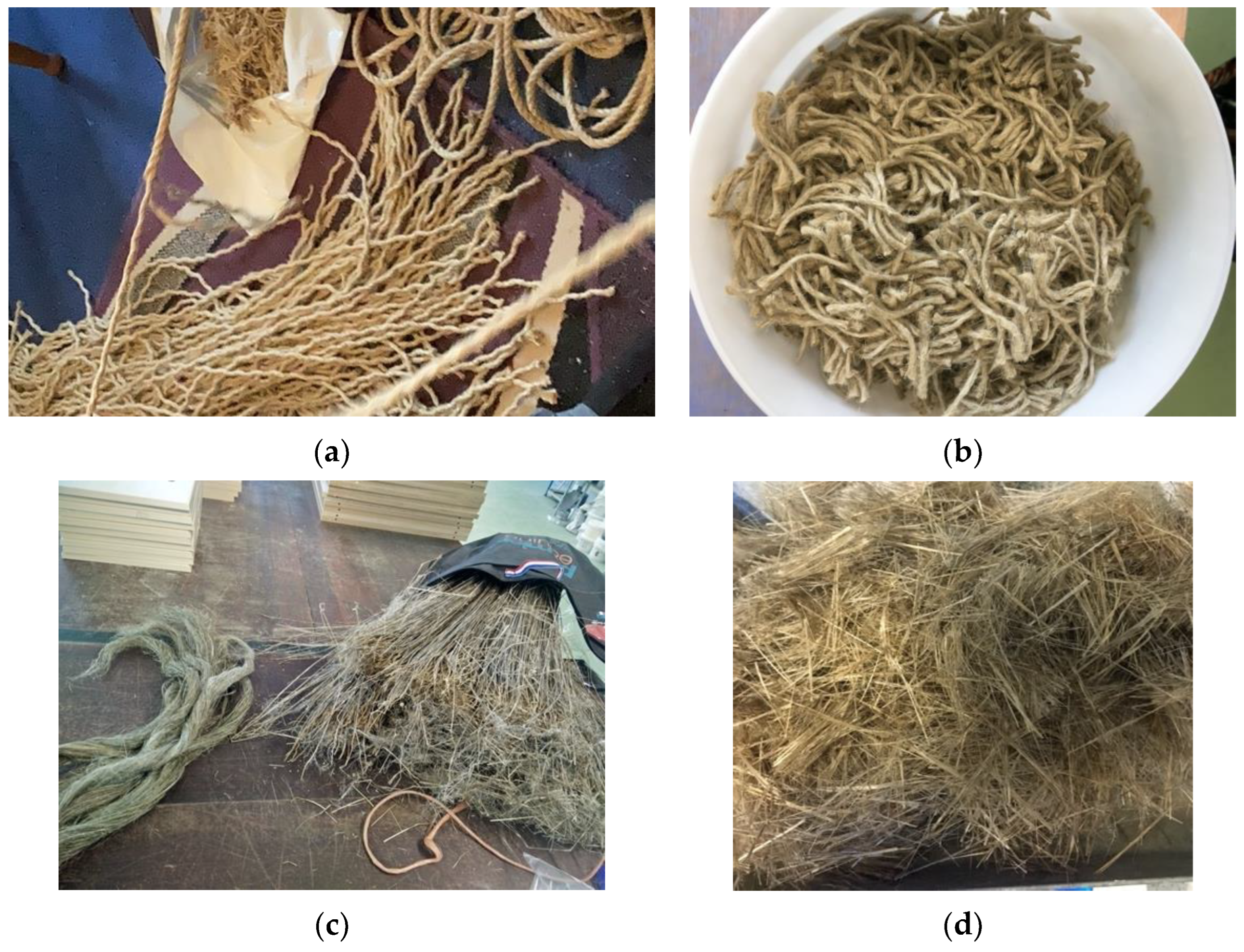
Hemp fibres were acquired as ropes (
Figure 1a), manually separated, and cut into 40 mm lengths (
Figure 1b). The flax fibres were bought as retted straws (
Figure 1c) and were also manually extracted, separated, and chopped into 40 mm lengths (
Figure 1d).
2.1. Vegetable Fibres
This section details the methodology adopted to submit the selected vegetable fibres for chemical surface treatment and to have some of their properties evaluated. To be able to discuss and compare the results in the following section, the preliminary study was conducted [
26], and the fundamental content for this analysis is summarised in the following section.
2.1.1. Untreated Fibres Analysis: Preliminary Study
Once ready, representative samples of the fibres were separated, and their densities were measured using a digital balance (rolbatch RBDT-01). Secondly, specimens of hemp and flax fibres were made, following the parameters given by the Standard Test Method for Tensile Strength and Young’s Modulus of Fibres (ASTM C1557) [
27]. Each sample containing 40 specimens was tested by attaching a single 40 mm long fibre into a paper. Using a tensiometer machine, the stress and elongation of each specimen were tested until it broke. The digital balance and a tab being tested are shown in
Figure 2a,b, respectively [
26].
Following the rupture, the diameters of the fibres were measured more than once close to the broken part, as recommended by ASTM C1557, using a digital microscope (
Figure 2).
As the vegetable fibres presented significantly lower properties in comparison to basalt, surface treatment can be considered as an option to enhance their behaviour.
The individual mean value was adopted to calculate the tension at the breaking point, Young’s modulus (elastic’s modulus) (E), and elongation at break (
), and the results are presented in
Table 3. They will be considered when analysing the effects of the surface treatments on the flax and hemp fibres.
2.1.2. Initial FRC Mixture
The initial control mix was designed following the ACI method, and the quantity of each material is detailed in
Table 4. The target compressive strength was 32 MPa (including 8% of standard deviation and 2.5 N/mm
2 of margin, slump 10–30 mm).
2.2. Surface Treatment and Mechanical Properties of the Fibres
From a list of surface treatments for vegetable fibres suggested by Sood and Dwivedi [
14], different types of solutes and solvents were selected for a broad view of their effects. Among all the options mentioned, the following solutions were chosen: an acid saline (EDTA), an acid oxide (KmnO4), a fatty acid (stearic acid), and an alkali solution (NaOH) in different concentrations. Each solution was produced as presented in
Table 1. To avoid damage to the internal layers of the structure of the fibres, as pointed out by Nayak (2020) [
16], the samples of hemp and flax fibres were treated for 4 h, 6 h, 10 h, 15 h, and 24 h.
Once all the solutions were prepared, individual samples of the fibres were fully submerged into separate beakers (
Figure 3a,b). When each time studied was reached, the solutions were neutralised, washed (
Figure 3c), and left to dry in the oven at 60 °C (
Figure 3d) for 24 h. Once dry, the fibres were separated, and new samples were made containing 17 specimens of single fibres of 40 mm length and had their mechanical properties evaluated following the same procedure previously described.
The results obtained are presented in the next section. The fatty-acid solution with stearic acid was adopted considering the study from Page et al. (2021) [
17] and for being a chemical present nature. Analysing the effects of all treatments, it was then possible to select the surface treatments for those fibres to be used as concrete reinforcement. The parameters adopted are also explained in
Section 3.
2.3. Degradability Test of Fibres in Alkaline Solution
To better understand the behaviour of the treated fibres in the concrete mixture, an experiment was carried out to evaluate their degradability in an alkali environment. As no specific standard procedure for this test was found, it was decided to adapt the methodology described by the ASTM D6942-03 (2019) “Standard Test Method for Stability of Cellulose Fibers in Alkaline Environments” [
28]. Since the whole fibres were the object of interest, instead of working with the pulp of fibres, 10 g of the whole fibres were used, and 23.3 g of 1N NaOH (pH 14) was added. Corresponding to a consistency of 30%, 10 g fibres was used, totalising 33.3 g.
Samples were immersed in the alkaline solution for 3, 7, 14, 21, and 28 days, respectively. Upon completion of their respective immersion periods, the samples were removed, and their tensile strength was measured. In addition, those immersed for 28 days were examined using SEM prior to tensile testing.
2.3.1. FTIR
To estimate the effects of each treatment on the composition of the fibres, they were analysed using a PerkinElmer Spectrum One FTIR Spectrometer, as shown in
Figure 4. Results and discussions are provided in the following sections of this paper.
2.3.2. SEM Images
To be able to compare the aspects of flax and hemp fibres in the natural and degraded forms as well as the effects of the surface treatment on them, SEM images were made and are presented in
Section 3.
2.4. Vegetable Fibre Reinforced Concrete
From the initial study, it was observed that having the maximum size of aggregate as 25 mm would limit the thickness of the structures produced, not allowing a possible usage for hollow concrete blocks of thinner panels, so for this part of the study, a new mix was designed where the coarse aggregate size was limited to 10 mm.
The mix studied here is an optimisation of a previous study (mix 1) [
26] using a concrete mixture containing 1:1.53:1.08:2.16:0.44 [cement]:[fine = aggregate]:[coarse aggregate 10 mm]:[w/c ratio].The objectives were to reduce the maximum nominal size of the coarse aggregate and to increase the mix workability by adopting a higher w/c factor.
The concrete mixture (mix 2) was designed following the ACI method. As in the initial experiment, the target compressive strength was again 32 N/mm
2 at 28 days, with a maximum size of coarse aggregate of 10 mm. Choosing a smaller coarse aggregate size, the mixture could have different applications depending on their behaviour, including the production of masonry blocks, thinner precast, and 3D printed structures. The water/cement ratio was reduced from 0.8 to 0.5 to avoid shrinkage and cracking [
29,
30]. The proportion calculated was 1:1.78:2.16:0.5 [cement]:[fine aggregate]:[coarse aggregate 10 mm]:[w/c ratio].
The designed slump was 30–60 mm, as it was expected that the fibres would absorb moisture from the mixture.
Following the preliminary part of this work as a reference for starting quantities, the initial proportion of fibres per volume was 0.5%. Different authors suggest the addition of 1% or less of natural fibres into a concrete mix [
21,
26,
31,
32]. For flax fibres, the same amount was also adopted. However, the workability was strongly affected. Therefore, mixes containing 0.35% and 0.25% of flax fibres were made, focusing on obtaining a homogeneous, workable, and mouldable mixture.
The initial mixtures produced were:
- i.
Control, no addition of fibres
- ii.
Basalt fibres (48 mm)—0.5%
- iii.
Hemp Fibres—0.5%
- iv.
Flax fibres—0.5%
- v.
Flax fibres—0.35%
- vi.
Flax fibres—0.25%
Aiming for the optimisation of the workability of a flax-reinforced mixture, two other mixes were produced. As the mix containing 0.25% presented a satisfactory slump, the mix was repeated to verify their compressive strength at both 7 and 28 days.
As a benchmark, mixtures containing polypropylene and basalt fibres were also tested for compressive strength. The flexural strength of the polypropylene FRC mixes was reported elsewhere [
24] and is used again here for comparison.
2.4.1. Compressive Strength (fcu)
Following the standards EN 12390-1/2/3 [
33,
34,
35], 6 cubes were moulded measuring 100 × 100 × 100 mm for each mixture, 3 to have their compressive strength tested at 7 days and 3 to be tested at 28 days.
2.4.2. Fracture Energy (Gf), Young’s Modulus€ and Residual Flexural Tensile Strength(f)
Although metallic fibres were not part of this study, the parameters from the standard EN 14651 (2012) Test method for metallic fibre concrete—Measuring the flexural tensile strength (limit of proportionality (LOP), residual)” [
36] were followed as recommended by the IS EN 14845-2:2007 “Test Methods For Fibres In Concrete—Part 2: Effect On Concrete” [
37].
Hence, 6 beams measuring 15 × 15 × 550 mm were produced to have their flexural tensile strength tested at 7 and 28 days. From the following methodology, it was possible to experimentally measure from the EN14651 the flexural tensile strength and calculate the fracture energy (Gf), Young’s modulus € and residual flexural tensile strength (f) as described above.
To better understand how these properties are calculated, the measurements adopted on each equation are detailed in
Figure 5, and the fracture energy (Gf) can be calculated through Equation (1) and the elastic module (E) through Equation (3).
where
W0 is the area below the curve on the Load [N] × Diffraction [m] diagram, m is the mass of the specimen (kg), g is the gravity acceleration [m/s
2],
δ represents the deflection at the final failure of the specimen [m], and
A the area [m
2] calculated by Equation (2).
The elastic modulus, or Young’s modulus, represents the stiffness of materials. Higher values indicate more brittleness, while lower values represent ductile materials.
where
V1 and
α can be obtained from Equations (4) and (5)
Flexural Strength (FL), (Fn) [MPa]
Following EN14651, the limit of proportionality (LOP) is calculated from Equation (6). For the peak strength (F
n), F
L is the value of the peak load [N], and for the residual strength at net deflections, F
j is the correspondent load [N] at specific deflection δ
j(N) points and used to calculate the residual flexural tensile strength (f
R,j) as shown in Equation (7).
where S is the span, b is the width measurements from
Figure 5 and peak strength (F
n), F
L is the value of the peak load [N], and for the residual strength (F
R,j) at net deflections, F
j is the correspondent load [N] at specific j deflection points.
Values of F
L and F
j were extracted from the load vs deflection points obtained from the 3-point bending tests; a
0, b, and d from measurements taken using a Vanier calliper for each specimen, and values for flexural strength at the peak load and the residual strength were calculated for net deflections j, from
Table 5.
The residual strength was calculated following the NF EN 14651, and as mentioned, the diagrams used were load vs deflection instead of CMOD, respecting the parameters established on the standard and following the procedure previously detailed in the literature review.
2.4.3. Thermal Conductivity
To assess and compare the impact caused by the fibre reinforcement in the heat transfer, a slab measuring 50 × 300 × 300 mm for each mixture was studied. The procedure followed was the ISO 8301 (1991) [
37] and the manual for “Thermal Conductivity of Building Materials” [
39]. Each slab was tested for at least 3 h through the steady boxes method. Thermal resistance was calculated based on readings taken every minute throughout the test.
Figure 6 shows the equipment used to obtain the thermal conductivity by the boxes method works according to Bala and Gupta (2021) [
40]. On the top of the box, there is a hot plate and, on the bottom, a cold plate. Their temperatures are controlled by an electric heater, and the cold plate uses water to keep its temperature steady.
Thermal conductivity represents how heat is transferred from one surface of the specimen to the other. Each specimen was placed in between 2 plates, and the temperature was increased on one side of it. The temperature difference was measured by the equipment on the opposite plate every minute.
Having the thickness (
) [m] of each specimen measured, the thermal conductivity (
is calculated using Equation (8).
where f is the equipment calibration factor and e is the heat flow meter output [mV/m
2]. Results are presented in
Section 3.
2.4.4. Water Penetration
To measure water penetration depth, 3 cubes measuring 150 × 150 × 150 mm were moulded and cured for 28 days. The standard method followed was the I. S. E. 12390-8:2009 “Testing hardened concrete—Part 8: Depth of penetration of water under pressure” [
41].
The cubes were placed into the equipment, where pressurised water was forced into one surface of the cubes for 72 h. After this period, the cubes were split in two, using a compressive one-point load applied on the centre of each cube, as shown in the sketch from
Figure 7a. After having them divided, the water penetration depth (p) was measured using a vernier calliper
Figure 7b.
2.4.5. SEM Images
To analyse the microscopic differences throughout the time on the internal aspect of the concrete surface of the proposed mix containing 0.25% of flax fibres, SEM images were made from samples of it after 28 days and over 90 days.


