Article

Influence of Roller Configuration on the Fiber–Matrix Distribution and Mechanical Properties of Continuously Produced, Mineral-Impregnated Carbon Fibers (MCFs)

Institute of Construction Materials, Technische Universität Dresden, 01062 Dresden, Germany
*
Author to whom correspondence should be addressed.
Fibers 2022, 10(5), 42; https://doi.org/10.3390/fib10050042
Submission received: 19 April 2022 / Revised: 27 April 2022 / Accepted: 5 May 2022 / Published: 7 May 2022
(This article belongs to the Special Issue Mechanics of Fiber Reinforced Cementitious Composites)

Abstract

:
The article at hand is envisaged to enumerate significant technological parameters for the successful impregnation of carbon fiber rovings having 50,000 (50 K) filaments, each within a fine-grained, cementitious suspension. Parameters such as the number of rollers as well as the influence of roller deflection and rotation have been investigated and discussed with regard to the quality of the related impregnation and mechanical properties resulting therefrom. Morphological analysis disclosed distinct differences in the fiber matrix distribution, which are particularly reflected in the flexural performance of the mineral-impregnated carbon fibers (MCFs) produced. Moreover, with the best fiber matrix distribution, uniaxial tensile tests on MCFs demonstrated superior tensile strengths, moduli of elasticity, and elongations at rupture.

1. Introduction

Carbon-fiber-reinforced concrete (CFRC) has great potential to replace conventional steel-reinforced concrete and to revolutionize building practice because it saves considerably on material resources and energy [1,2]. The non-corrosive behavior and the high mechanical performance of the carbon fibers (CFs) allow the building of lightweight, thin-walled structures with exceptional mechanical properties and high durability [3,4].
To ensure full load-bearing between the continuous CF reinforcements and the surrounding concrete matrix, several thousand individual CF filaments can be commonly bundled in the form of yarns and textiles by applying polymeric impregnation matrices, resulting in substances often described as carbon-fiber-reinforced polymers (CFRPs) [5,6,7]. Nowadays, these kinds of composites have been applied increasingly to strengthen existing concrete structures [8,9]. However, entirely new, large-scale buildings have been hitherto difficult to realize because insufficient temperature resistance above 100 °C and compatibility with concrete and masonry substrates underlies these state-of-the-art reinforcements. When the environmental temperature reaches or exceeds the glass transition temperature of the polymers, their chain mobility increases drastically, followed by a significant reduction in strength and stiffness, finally resulting in the bar or textile reinforcements’ considerably reduced mechanical performance [10,11,12,13,14] arising out of the weakened bond strength within concrete matrices [15,16,17,18].
Hence, more temperature stable materials, such as fine reactive pozzolanic particles [19,20,21], have been investigated to enhance the fiber–matrix interphase. A very promising approach in overcoming this temperature issue lies in utilizing impregnation matrices based on inorganic mineral binders, such as cement or aluminosilicates, to fabricate so-called mineral-impregnated carbon fibers (MCFs), which exhibit significantly higher temperature resistance, ensuring sufficient load-bearing capacity up to 500 °C [17,18,22] and comparable tensile properties to conventional CFRPs [23,24,25]. Moreover, this novel reinforcement type MCF brings several further advantages, namely, their low material cost, better compatibility with cementitious materials, flexibility in shape, automated manufacture [24], and possibilities for their direct integration into emerging 3D printing processes [26].
However, during the continuous production of MCF, the specific geometrical features and hydrophobic nature of the CF yarns are a challenge in impregnating them with water-based, mineral particle suspensions. The sizes of the mineral particles used in concrete technology usually differ clearly from the sizes of CFs, and the coarse filler geometries may additionally hinder high packing densities in the composites [19,24]. Even with particle sizes in the range of the filament diameter (~7–9 µm) or even smaller, it is still challenging to realize the complete homogenous impregnation of entire CF yarns with up to 50,000 (50 K) filaments each [17], acting as a kind of filter and thus hindering the penetration of mineral fines into the yarn core. Although the wettability of CF can be improved by different surface treatments [27,28,29,30,31,32], capillary forces alone cannot provide the required quality of the traditional composite industry without applying mechanical pressure to the rovings [33,34,35].
Hence, the application of mechanical force onto the roving is an indispensable prerequisite for efficient, reproducible production and excellent fiber–matrix distribution for high-performance MCF. Such required forces or pressure can be generated by a multiple deflection roller configuration, which can demonstrably increase the impregnation rate in continuous production [24,36]. Recently several studies have reported on the application of various configurations and suspension compositions in mineral impregnation. Peled et al. [37] and Schneider et al. [27] performed initial experiments using simple, manual impregnation methods on cement suspensions and carbon yarns with a relatively low number of filaments, resulting in limited impregnation qualities. Better results have been achieved with Foulard-based systems combined with subsequent pultrusion, as often applied in the FRP composite industry. Such processes enable the fabrication of pultruded profiles of virtually unlimited length, exhibiting high flexibility and desirable mechanical properties [38]. Several subsequent, individual studies each used a manual single roller [28] and three [17,18,30] or five assisting rollers [26] as well in a pultrusion process to impregnate 50K CF heavy tows with cementitious suspensions. With the application of a three-roller Foulard, similar CF yarns have also been impregnated with a sol–gel system [39]. Moreover, several studies [40,41,42] have focused on the production of continuous CF yarns impregnated with a geopolymer (GP) without presenting the roller configuration in detail. Zhao et al. [23] conducted continuous impregnation of the CF heavy tow with a GP suspension in a five-roller Foulard system and obtained high-quality fiber–matrix distribution. However, it is clear that to optimize the design, fabrication, and performance of MCF, more knowledge and, in turn, better understanding of the processing parameters is needed.
Here, a systematic study of the roller configurations with regard to impregnation quality and the final MCF performance is reported. Thereby, the number of rollers, their deflection, and their rotation were systematically varied for the impregnation of CF yarn with 50,000 (50 K) filaments in a fine-grained, cementitious suspension. Subsequently, the composites were morphologically and mechanically characterized to assess the role of impregnation quality regarding the mechanical properties of the MCF obtained.

2. Experimental Program
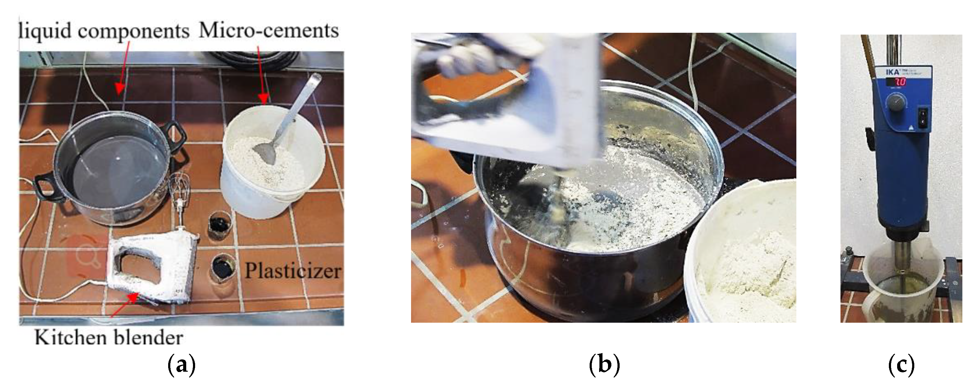
2.1. Materials

A commercially available CF heavy tow SIGRAFIL®C T50-4.4/255-E100 from SGL Group® with epoxy sizing, 50,000 (50 K) individual filaments, and a fineness of 3450 tex was used for the investigation. Further material parameters are given in Table 1.
Mikrodur R-X® and Mikrodur P-U® from Dyckerhoff®, Wiesbaden, Germany, were used as hydrating components of the cementitious suspension, having a w/b ratio of 0.8. Additionally, a micro-silica suspension of Centrilit Fume SX® from MC-Bauchemie®, Bottrop, Germany, with a solid-to-liquid mass ratio of approximately 50% was used as a silica source. The ultrafine cements and the micro-silica suspension were mixed in a ratio of 1:1:1 by mass, which corresponds to a mass proportion of approximately 30% blast furnace slag, approximately 50% Portland cement clinker, and 20% micro-silica in the total reactive binder. The desired flow state of the impregnation suspension was obtained using a naphthalene–sulfonate-based plasticizer: MasterRheobuild 30 from Dyckerhoff®, Wiesbaden, Germany. The exact mixing ratios and weights of the impregnation suspensions are presented in Table 2.

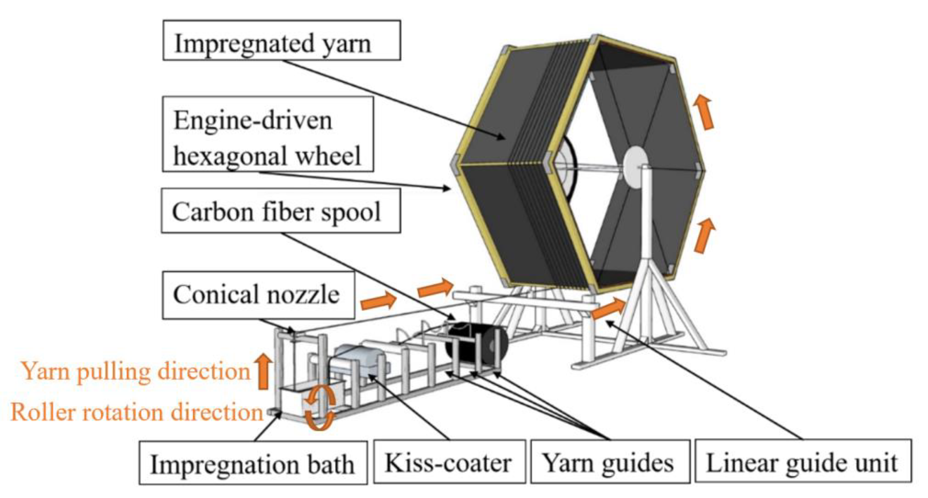
2.2. Fabrication and Post-Treatment of MCF

A standard kitchen mixer was used to premix 3 L of the impregnation suspension. The micro-cements were manually added, stepwise, to the premix, mixing water, the micro-silica suspension, and the first portion of the plasticizer, i.e., plasticizer start. In this stage, mixing was initially performed at relatively high viscosity to attain the high shear forces necessary to disperse the fine materials adequately, as shown in Figure 1. Subsequently, the consistency required for impregnation was achieved by adding the remaining plasticizer, i.e., plasticizer end. Finally, the mixture was completely homogenized by means of a disperser using T50 digital ULTRA-TURRAX® apparatus, equipped with an R 50 stirrer shaft and an R 1402 dissolver disc with a diameter of 42 mm, for 2 min, at a speed of 7000 rpm. The rheological properties of 1.5 L suspension were characterized according to DIN EN 445. Via a Marsh funnel test, flow times for the first liter and the second half liter of 40 s and 35 s were measured, respectively [44].
The automated fabrication of the MCF was conducted using a continuous pultrusion process, as depicted in Figure 2. The CF yarn was pulled by winding it onto a large hexagonal, motor-driven wheel and passing it through yarn guidance, an engine-driven kiss-coater, and a suspension bath containing the Foulard roller-systems. With this Foulard system, the variation in the number of rollers, deflection degree, and rotation was achieved as summarized in Table 3, and described in the respective Section 3.1, Section 3.2, Section 3.3. The diameter of each applied roller was 4.2 cm. A pulling velocity of 12 m/min was set to ensure economic industrial production in future. Three yarn guiding levels were applied to level the yarn and avoid excessive lateral variations. Finally, the freshly pultruded yarns were shaped by a conical nozzle with an inner diameter of 4 mm. Subsequently, the pultruded yarn elements were placed on the hexagonal wheel side by side at certain intervals without any disturbance arising from the yarn contact among the segments, achieved by a linear guide unit controlled by an engine. The edge length of the hexagon was 1.20 m, which ensured straight yarn elements of at least 1 m in the following analyses of the MCF fresh state. After hydrating on the wheel for 7 d at ambient temperature, the samples were immersed in a water bath for another 7 d before storing under a standard laboratory climate (20 °C, 55% relative humidity) until testing.

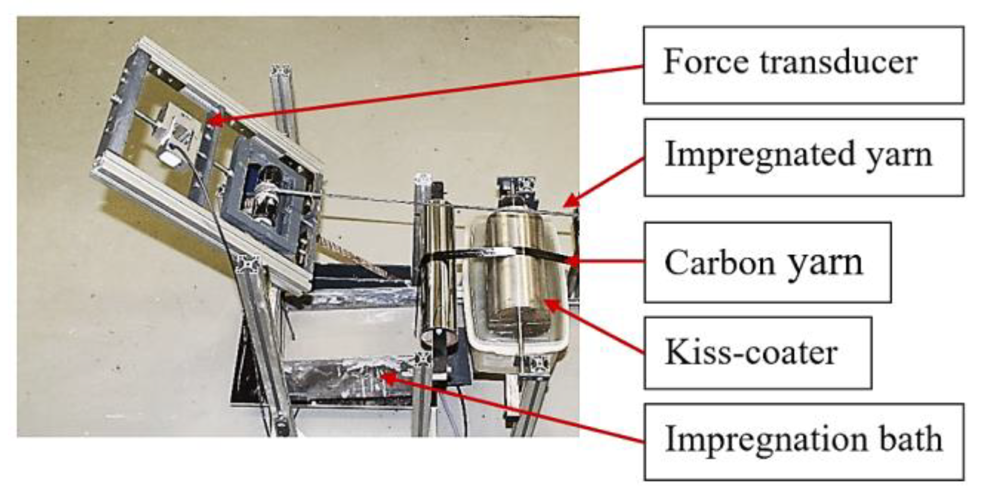
2.3. Characterization of Fresh-State Properties of MCF

The stresses occurring on the CF roving during the pultrusion process comprised tensile stresses from the alignment as well as shear stresses among the fibers, the matrix, and the roller surfaces [45]. Hence, for each set of parameters, the forces were monitored by a force transducer (Typ S2M, HBK, Darmstadt, Germany) after final yarn shaping with the nozzle, as shown in Figure 3. Moreover, the impregnation quality of the MCF was measured via the ratio of mass to the length of the freshly pultruded CF yarns. Thus, impregnated yarns with lengths of 1.0 m were cut off immediately and weighed. Three measurements were carried out for each reported mean value.

2.4. Mechanical Testing of MCF

The flexural characteristics of the MCFs were evaluated by conducting three-point bending tests in a displacement-controlled machine: Zwick Roell Z 1445 (load cell: max. 1 kN), adapted from ISO 14125:1998 for fiber-reinforced plastic composites.
Ten specimens at an MCF age of 28 d were tested for each variant, with a support span of 100 mm and a displacement rate of 5 mm/min.
Uniaxial tension tests were performed in accordance with ISO 10406-1 [46], using a servo-hydraulic machine EU 20 (GERMANY) with a max. load capacity of 10 kN. A total specimen length of 600 mm was used with a free length of 410 mm and the end anchorage length on either side of 95 mm. More details and the scheme of the experimental setup are reported in [23]. Ten specimens were tested for each processing condition at an age of 28 d. Deformation measurements were performed with an electro-optical video extensometer (Rudolph XR200) with a gauge length of 100 mm and located in the central area of the specimen. The recordings of the load and strain were conducted using a SIRIUS®HS-STG data logging system from DEWEsoft® with a sampling rate of 5000 s-1 and a filter of 100 Hz. Each reported value was calculated by taking the average of at least ten measurements. The uniaxial tensile strength of MCF was determined by considering the sum of all filament cross-sectional areas of the impregnated yarn, which is usually used to characterize the yarn strand or textile reinforcement under uniaxial tensile loading for carbon textile-reinforced concrete [47,48,49]. The E-modulus (E), as a measure of MCF stiffness, was calculated according to Equation (1):
E = ∆σ/∆ε,
where ∆σ and ∆ε denote the difference in tensile stress and tensile strain in the linear elastic range of the stress–strain diagram between 20% and 70%, respectively.

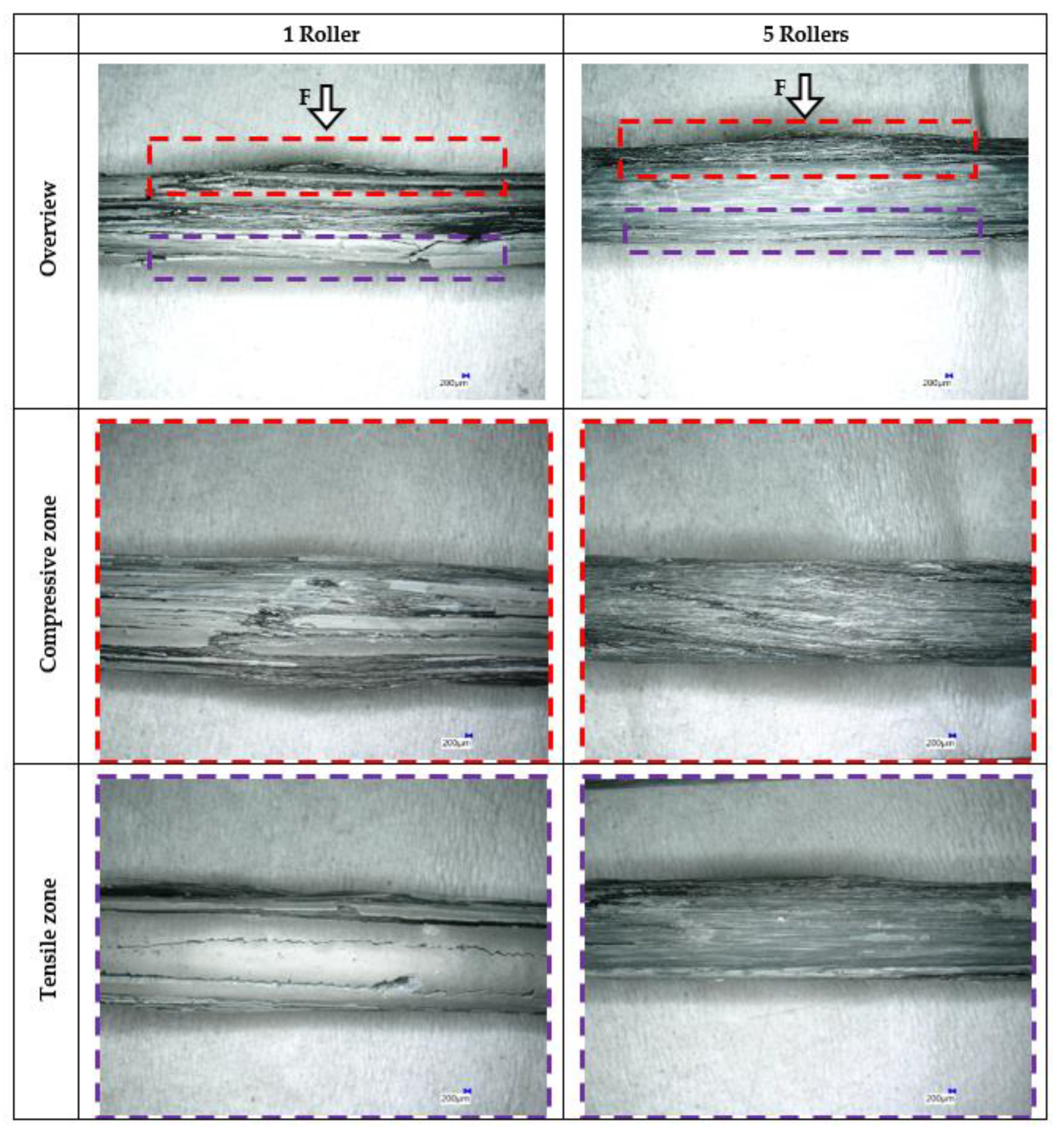
2.5. Morphological Characterization

The microstructural features of the MCF were characterized by means of a Quanta 250 FEG environmental scanning electron microscope (ESEM), supplied by FEI, Eindhoven, The Netherlands, on yarn cross-sections. The MCFs were impregnated with an epoxy resin, sawed after polymerization, and subsequently polished until achieving a smooth reflecting surface. To analyze the relationship between the MCF morphology and the failure behavior after bending tests, µCT analysis was conducted using a dynamic CT-XPRESS from ProCon X-ray, Germany, at 95 kV and 132 mA. Scans proceeded from 0° to 360° on each cross-section with 0.5° angular increments. The images were reconstructed using X-AID software.

3. Results

3.1. Morphological Characterization

One, three, and five freely rotatable impregnation rollers with a high yarn deflection were investigated, as seen in Figure 4. Their influence on the total pulling force during impregnation and the mass/length ratios obtained on the freshly processed MCF are given in Table 2 and Table 4. As can be seen, a significantly higher pulling force was observed with an increasing number of rollers, a result which can be explained by the increased shear stresses due to increased contact area between the yarn, the suspension, and the rollers, as well as tensile stresses occurring due to the high deflection. By using one roller, the impregnating process was conducted on one side only, whereas multiple roller deflections applied pressure several times on both and increased the number of contact areas [50]. This yielded the observed gradual increase in the mass/length ratio of the freshly impregnated MCF, which is an additional indication of a higher degree of penetration, as also reported in previous studies [36,51] for polymer impregnation technologies.
Morphological analysis confirmed clear differences in the impregnation quality of the MCF made with different numbers of rollers, as shown in Figure 5. Notably, the black areas are carbon filaments and their corresponding bundles, whereas the bright areas represent the cement matrix. Considering the MCF produced with one roller only, significant separated areas of CF filaments and matrix can be observed as well as an unregularly cross-sectional shape, confirming a poor impregnation degree of the suspension over the entire yarn; hence, a non-uniform fiber–matrix distribution. Notably, during manufacturing, the roving was only slightly penetrated with cement suspension and rather folded during final shaping.
In contrast, considerable improvement in fiber–matrix distribution was achieved when applying more rollers, as shown for the five-roller configuration in Figure 5c,d on the right. Composites produced in such a way exhibited only a few accumulations of filaments and matrix-rich areas, indicating a better impregnation quality of the suspension materials into the whole yarn, which is in line with the measured mass discussed above. Moreover, better fiber–matrix distribution also results in a better shape stability, as clearly seen by the obtained circular cross-section for the MCF made with five rollers. This can be traced back to the immense capillary forces acting on the 50,000 individual CF filaments within the mineral suspension, ensuring favorable shape stability after leaving the conical nozzle.
The differences observed in the fiber–matrix distribution are also related to the considerable changes in the mechanical properties of the MCF, as shown in Figure 6. It can clearly be seen that, in particular, the flexural performance of the composites reflects the fiber–matrix distribution. With an increasing number of applied rollers, the fiber–matrix distribution is significantly enhanced and the MCFs produced yielded a pronounced improvement in their maximum flexural force. For the MCF made with one roller only, 39 N was achieved, whereas the MCFs fabricated with five rollers yielded 105 N.
Figure 7 shows the morphological appearance of the damaged MCF after bending tests, investigated by optical microscopy. Clear differences can be seen regarding the applied roller number and obtained fiber–matrix distribution. The MCF made with one roller only exhibited a brittle failure mode with coarsely deformed matrix areas. In the compressive zone (marked in red), pronounced fiber kinking and matrix cracks are observable, whereas in the tensile loaded zone (marked in purple), merely a brittle matrix cracking is found. The latter can mainly be traced back to an uneven fiber–matrix distribution from the insufficient impregnation process. Instead, the MCF made with five rollers clearly shows a more finely cracked failure mode due to the better fiber–matrix distribution.
More insights on the deformation behavior were found through micro-computed tomography (µCT), as shown in Figure 8. Notably, the specimen components are colored in different shades of grey depending on their density. Black areas and dark grey areas represent air, meaning cracks or void as well as plain carbon filaments having low densities. For the MCF made with one roller, a pronounced laminated shear failure is seen throughout the sample, with fiber breakage and matrix cracking in the compression zone. This is explained by uneven stress distribution over the yarn cross-section and an insufficient crack-bridging behavior with poor fiber–matrix distribution.
With enhanced fiber–matrix distribution—MCFs made with five rollers—an efficient shear–stress transfer between the matrix and individual filaments could be realized, leading to a more homogenous deformation over the cross-section [52]. Nevertheless, also for the well impregnated MCFs, fiber and matrix breakage occurred, as well as delamination.
The better impregnated MCF also exhibited a clearly higher tensile strength and elongation-to-rupture, whereas those differences were less prominent compared with the flexural performance. However, for the MCF with the best fiber–matrix distribution, a tensile strength of 2456 MPa was achieved, whereas for MCF made with one roller, the worst fiber–matrix distribution, only 1915 MPa could be obtained. Notably, more fiber damage might have arisen from increased contacts with the rollers [53], whereas more inherent imperfections of the filaments could be bridged by the matrix with better impregnation quality. Hence, improved tensile performance was mainly explained by superior stretching and alignment of the filaments in the bundle [54] and, with better impregnation quality, by the bridging behavior during deformation. However, the E-moduli of all MCFs ranged between 220 and 230 GPa and seemed to be less affected by the impregnation quality, but rather are predominantly determined by the CF properties themselves.

3.2. Roller Assembly

An industrial manufacturing process with impregnation rollers requires appropriate yarn deflection by the assembled rollers [33]. As described in Section 3.1, high-quality impregnation was achieved when applying three and five rollers; therefore, those approaches were further investigated with two different degrees of deflection, as presented in Figure 9. The yarn deflection was varied by regulating the relative vertical position of the applied rollers. The higher yarn deflection angle resulted in increased contact surface area along the rollers in Figure 10, namely, longer contact time and therewith higher applied pressure onto the fiber rovings or increased impregnation forces, respectively.
Table 5 confirms that the pulling force increased during processing with high deflection, namely, for the three and five applied rollers, by 44% and 37%, respectively. Additionally, higher deflection delivered increased mass/length ratios of the freshly impregnated yarns. For both systems investigated, high deflection clearly showed a higher suspension content, demonstrating better impregnation of the multifilament yarn. In addition to the abovementioned increase in contact area, this is potentially also traced back to an increase in the stresses occurring around the yarn deflection points. With higher deflection, more stresses occur in the contact areas between the multifilament and suspension, which may press the mineral suspension more intensely into the core of the yarn, resulting in an increased fiber–matrix distribution.
Figure 11 shows the results of the mechanical performance of MCFs when various yarn deflection degrees are applied. The use of high yarn deflection generated a considerable increase in maximum flexural force, which is attributed to the improved impregnation quality, as measured by the fresh properties of the MCFs above.
Under uniaxial tension, the MCFs produced with higher deflection exhibited a slight increase in tensile strength and strain at failure as well as unchanged E-moduli when using five impregnation rollers. However, in the case of the three-roller arrangement, the tensile properties of the composites could not be significantly changed by the strong yarn deflection, likely related to the limited improvement in impregnation quality when using fewer rollers. The tensile strength and the E-modulus of MCFs produced with a strong yarn deflection remained unchanged, and their failure strain decreased slightly as compared with the weak yarn deflection.

3.3. Rotation of Rollers

In the final experiment for the three roller systems, the controlled rotation of the central roller was investigated, as depicted in Figure 10. When all rollers rotated freely, they ideally possessed the same speed, equal to the yarn pulling velocity, as shown in Figure 12a. For the “fixed” configuration, the central roller was held in place by a magnet from outside the suspension bath, as depicted in Figure 12b. The “pressed” configuration, shown in Figure 12c, comprised the freely rotating rollers and one additional locked roller with a diameter of 3.6 cm and 10 N perpendicular load. Finally, the central roller was driven by a motor counter-rotating, as in Figure 12d, or co-rotating, as in Figure 12e. For the counter-rotating roller, the same velocity as the yarn pulling speed was chosen, whereas for the co-rotating configuration, the central roller was driven by the motor with double the yarn-pulling speed.
In Table 6, a clear influence of these roller configurations on the pulling forces and the corresponding mass/length ratios of the freshly prepared MCF can be seen. Compared with freely rotating rollers, the pulling forces increased by 31%, 43%m and 41%, respectively, for the “fixed”, “pressed”, and “counter” configurations, but reduced by 38% for the co-rotating system. This clearly shows that applied roller rotations could significantly tailor the tension occurring during the impregnation, a development which can be of significant interest for large-scale production, e.g., the pultrusion of several CF heavy tows.
Considering the mass/length ratios of the corresponding composites, the usage of the fixed roller led to a slight reduction compared with the freely rotating roller configuration. This was probably attributable to an insufficient supply of impregnation suspension by the fixed roller. Hence, non-fixed cylindrical roller systems are obviously beneficial for the impregnation process, which is in good agreement with previous studies on polymer composites [55,56].
Among the controlled roller rotation systems, the co-rotating roller configuration yielded the highest suspension content, because it enabled a constant supply of suspension during the whole impregnation process. The mass/length ratio of the fresh MCF produced with the pressed roller was marginally higher than that of the free-rotating roller configuration, although the additional pressed roller increased the impregnation pressure and simultaneously promoted the penetration of the suspension from the two sides [57]. For the counter-rotating configuration, the suspension content remained unchanged in comparison with the freely rotating system.
The morphological analysis of the free-rotating and counter-rotating rollers show more differences among the MCFs, as shown in Figure 13. As can be seen, the composites produced with three freely rotating rollers tended to have a round cross-sectional shape, but with irregular edges. The majority of the filaments were relatively evenly distributed in the matrix, with only a few accumulations of filaments and matrix-rich areas. However, the filaments were very close to each other and only slightly surrounded by matrix material, as shown in Figure 13b. More uniform filament–matrix distribution over the cross-section can clearly be observed for MCFs produced with the counter-rotating configuration, exhibiting fewer areas of filaments or matrix accumulations. At higher magnification, the individual filaments in this composite kept a certain distance from each other and were densely packed in the surrounding cementitious matrix, as depicted in Figure 13d.
In Figure 14, the mechanical performance of the MCFs produced with different roller rotation configurations is shown, revealing differences particularly in their flexural performance. Especially, applying the counter-rotating roller pronouncedly enhanced the maximum flexural force of the composites. This improvement can be attributed to the more uniform fiber–matrix distribution derived from the better impregnation quality, as shown above. The “fixed” as well as “pressed” systems only exhibit a slight increase in maximum flexural force. However, a reduction in flexural performance was observed for the MCFs produced via the co-rotating configuration, indicating a poorer fiber–matrix distribution. Moreover, potential fiber misalignments caused by the reduced yarn tension and fiber damage are possible, as presented in Table 6.
Similarly, the uniaxial tensile strength of the MCFs increased slightly when using the “fixed”, “pressed”, and “counter-rotating” configurations, but were reduced in the “co-rotating” system when compared with the normal free-rotating roller configuration. Moreover, the use of all above-mentioned rotation control systems led to similar E-moduli and a slight decrease in ultimate strain, probably due to unavoidable fiber damage with increasing yarn tension.

4. Summary

In this study, different impregnation roller configurations based on the Foulard method were designed to control the degree of impregnation of commercially available CF rovings with 50,000 (50 K) filaments as well as the mechanical properties of the obtained MCFs. The MCFs were fabricated with a micro-cement suspension in a continuous, automated processing line. The varied configuration parameters comprised the number of applied rollers, the degree of the roller deflection, and the rotation of rollers.
Microscopic studies revealed microstructurally distinct differences in the fiber–matrix distribution over the cross-section of the MCF obtained from the various roller configurations, which strongly influenced the shear–stress transfer within the bundle under mechanical loading, in particular, in their flexural performance. Hence, the three-point bending test is an excellent method to assess the impregnation quality of MCF or CFRP.
By increasing the number of rollers from one to five, better impregnation quality and a more uniform fiber–matrix distribution were achieved, which led to improvements in flexural and uniaxial tensile performance. Moreover, for the applied set-up, a more pronounced yarn deflection was favorable for better impregnation quality, which further enhanced the mechanical properties of the MCF.
For a three-roller Foulard system, it was found that the impregnation quality can be further tailored by defining roller rotation. As an optimized configuration, a counter-rotating roller was found to greatly improve the impregnation quality of the roving and the final composite performance.
In summary, the Foulard-based pultrusion process with specifically suitable roller configurations is an efficient method to rapidly and continuously produce MCF in an automated industrial line to obtain composites with mechanical properties in the range of conventional CFRP reinforcements.

Author Contributions

Conceptualization, M.L. and A.M.; methodology, M.L, J.Z., A.M., G.W. and K.W.; software, M.L., J.Z. and G.W.; validation, M.L, J.Z., A.M. and G.W.; formal analysis, M.L, J.Z., A.M. and G.W.; investigation, M.L, J.Z., A.M., G.W. and K.W.; resources, M.L. and V.M.; data curation, G.W. and J.Z.; writing—original draft preparation, M.L. and J.Z.; writing—review and editing, M.L., J.Z. and V.M.; visualization, M.L., J.Z., A.M. and G.W.; supervision, M.L., A.M. and V.M.; project administration, M.L. and A.M.; funding acquisition, M.L. and V.M. All authors have read and agreed to the published version of the manuscript.

Funding

This study was co-financed by tax funds on the basis of the budget adopted by the Saxon State Parliament. Moreover, J.Z. acknowledges the funding by the European Social Fund.

Institutional Review Board Statement

Not applicable.

Informed Consent Statement

Not applicable.

Acknowledgments

The authors acknowledge Simone Hempel for support in electron microscopy assays.

Conflicts of Interest

The authors declare no conflict of interest. The funders had no role in the design of the study; in the collection, analyses, or interpretation of data; in the writing of the manuscript, or in the decision to publish the results.

References

  1. Seifert, W.; Lieboldt, M. Ressourcenverbrauch im globalen Stahlbetonbau und Potenziale der Carbonbetonbauweise: Globale Herausforderungen des Bauwesens. Beton-Und Stahlbetonbau 2020, 115, 469–478. [Google Scholar] [CrossRef]
  2. Bohm, R.; Thieme, M.; Wohlfahrt, D.; Wolz, D.S.; Richter, B.; Jager, H. Reinforcement Systems for Carbon Concrete Composites Based on Low-Cost Carbon Fibers. Fibers 2018, 6, 56. [Google Scholar] [CrossRef] [Green Version]
  3. Scholzen, A.; Chudoba, R.; Hegger, J. Dünnwandiges Schalentragwerk aus textilbewehrtem Beton: Entwurf, Bemessung und baupraktische Umsetzung. Beton-Und Stahlbetonbau 2012, 107, 767–776. [Google Scholar] [CrossRef]
  4. Schumann, A.; May, M.; Schladitz, F.; Scheerer, S.; Curbach, M. Carbonstäbe im bauwesen: Teil 2: Verbundverhalten–verbundversuche an unterschiedlichen Carbonstäben. Beton-Und Stahlbetonbau 2020, 115, 962–971. [Google Scholar] [CrossRef]
  5. Hollaway, L. A review of the present and future utilisation of FRP composites in the civil infrastructure with reference to their important in-service properties. Constr. Build. Mater. 2010, 24, 2419–2445. [Google Scholar] [CrossRef]
  6. Pendhari, S.S.; Kant, T.; Desai, Y.M. Application of polymer composites in civil construction: A general review. Compos. Struct. 2008, 84, 114–124. [Google Scholar] [CrossRef]
  7. Bakis, C.E.; Bank, L.C.; Brown, V.; Cosenza, E.; Davalos, J.; Lesko, J.; Machida, A.; Rizkalla, S.; Triantafillou, T. Fiber-reinforced polymer composites for construction—State-of-the-art review. J. Compos. Constr. 2002, 6, 73–87. [Google Scholar] [CrossRef] [Green Version]
  8. Rajak, D.K.; Pagar, D.D.; Menezes, P.L.; Linul, E. Fiber-reinforced polymer composites: Manufacturing, properties, and applications. Polymers 2019, 11, 1667. [Google Scholar] [CrossRef] [Green Version]
  9. Gand, A.K.; Chan, T.-M.; Mottram, J.T. Civil and structural engineering applications, recent trends, research and developments on pultruded fiber reinforced polymer closed sections: A review. Front. Struct. Civ. Eng. 2013, 7, 227–244. [Google Scholar] [CrossRef]
  10. Bisby, L.A.; Green, M.F.; Kodur, V.K. Response to fire of concrete structures that incorporate FRP. Prog. Struct. Eng. Mater. 2005, 7, 136–149. [Google Scholar] [CrossRef]
  11. Holz, K.; Curbach, M. Zugtragverhalten von Carbonbeton unter Hochtemperaturbeanspruchung. Beton-Und Stahlbetonbau 2020, 115, 231–240. [Google Scholar] [CrossRef]
  12. Nguyen, K.T.; Navaratnam, S.; Mendis, P.; Zhang, K.; Barnett, J.; Wang, H. Fire safety of composites in prefabricated buildings: From fibre reinforced polymer to textile reinforced concrete. Compos. Part B Eng. 2020, 187, 107815. [Google Scholar] [CrossRef]
  13. Messori, M.; Nobili, A.; Signorini, C.; Sola, A. Effect of high temperature exposure on epoxy-coated glass textile reinforced mortar (GTRM) composites. Constr. Build. Mater. 2019, 212, 765–774. [Google Scholar] [CrossRef] [Green Version]
  14. Chowdhury, E.; Eedson, R.; Bisby, L.A.; Green, M.F.; Benichou, N. Mechanical characterization of fibre reinforced polymers materials at high temperature. Fire Technol. 2011, 47, 1063–1080. [Google Scholar] [CrossRef]
  15. de Andrade Silva, F.; Butler, M.; Hempel, S.; Toledo Filho, R.D.; Mechtcherine, V. Effects of elevated temperatures on the interface properties of carbon textile-reinforced concrete. Cem. Concr. Compos. 2014, 48, 26–34. [Google Scholar] [CrossRef]
  16. Kruppke, I.; Butler, M.; Schneider, K.; Hund, R.-D.; Mechtcherine, V.; Cherif, C. Carbon Fibre Reinforced Concrete: Dependency of Bond Strength on T g of Yarn Impregnating Polymer. Mater. Sci. Appl. 2019, 10, 328. [Google Scholar]
  17. Schneider, K.; Michel, A.; Liebscher, M.; Terreri, L.; Hempel, S.; Mechtcherine, V. Mineral-impregnated carbon fibre reinforcement for high temperature resistance of thin-walled concrete structures. Cem. Concr. Compos. 2019, 97, 68–77. [Google Scholar] [CrossRef]
  18. Schneider, K.; Michel, A.; Liebscher, M.; Mechtcherine, V. Verbundverhalten mineralisch gebundener und polymergebundener Bewehrungsstrukturen aus Carbonfasern bei Temperaturen bis 500 °C. Beton-Und Stahlbetonbau 2018, 113, 886–894. [Google Scholar] [CrossRef]
  19. Nadiv, R.; Peled, A.; Mechtcherine, V.; Hempel, S.; Schroefl, C. Micro-and nanoparticle mineral coating for enhanced properties of carbon multifilament yarn cement-based composites. Compos. Part B Eng. 2017, 111, 179–189. [Google Scholar] [CrossRef]
  20. Signorini, C.; Nobili, A.; Gonzalez, E.C.; Siligardi, C. Silica coating for interphase bond enhancement of carbon and AR-glass Textile Reinforced Mortar (TRM). Compos. Part B Eng. 2018, 141, 191–202. [Google Scholar] [CrossRef] [Green Version]
  21. Signorini, C.; Sola, A.; Nobili, A.; Siligardi, C. Lime-cement textile reinforced mortar (TRM) with modified interphase. J. Appl. Biomater. Funct. Mater. 2019, 17, 2280800019827823. [Google Scholar] [CrossRef] [PubMed] [Green Version]
  22. Junger, D.; Liebscher, M.; Zhao, J.; Mechtcherine, V. Joule heating as a smart approach in enhancing early strength development of mineral-impregnated carbon-fibre composites (MCF) made with geopolymer. Compos. Part A Appl. Sci. Manuf. 2022, 153, 106750. [Google Scholar] [CrossRef]
  23. Zhao, J.; Liebscher, M.; Michel, A.; Junger, D.; Trindade, A.C.C.; de Andrade Silva, F.; Mechtcherine, V. Development and testing of fast curing, mineral-impregnated carbon fiber (MCF) reinforcements based on metakaolin-made geopolymers. Cem. Concr. Compos. 2021, 116, 103898. [Google Scholar] [CrossRef]
  24. Mechtcherine, V.; Michel, A.; Liebscher, M.; Schneider, K.; Großmann, C. Mineral-impregnated carbon fiber composites as novel reinforcement for concrete construction: Material and automation perspectives. Autom. Constr. 2020, 110, 103002. [Google Scholar] [CrossRef]
  25. D’Antino, T.; Papanicolaou, C. Mechanical characterization of textile reinforced inorganic-matrix composites. Compos. Part B Eng. 2017, 127, 78–91. [Google Scholar] [CrossRef]
  26. Mechtcherine, V.; Michel, A.; Liebscher, M.; Schmeier, T. Extrusion-based additive manufacturing with carbon reinforced concrete: Concept and feasibility study. Materials 2020, 13, 2568. [Google Scholar] [CrossRef]
  27. Schneider, K.; Lieboldt, M.; Liebscher, M.; Fröhlich, M.; Hempel, S.; Butler, M.; Schröfl, C.; Mechtcherine, V. Mineral-based coating of plasma-treated carbon fibre rovings for carbon concrete composites with enhanced mechanical performance. Materials 2017, 10, 360. [Google Scholar] [CrossRef]
  28. Zhao, J.; Liebscher, M.; Michel, A.; Schneider, K.; Foest, R.; Froehlich, M.; Quade, A.; Mechtcherine, V. Plasma-generated silicon oxide coatings of carbon fibres for improved bonding to mineral-based impregnation materials and concrete matrices. Cem. Concr. Compos. 2020, 114, 103667. [Google Scholar] [CrossRef]
  29. Zhao, J.; Liebscher, M.; Tzounis, L.; Mechtcherine, V. Role of sizing agent on the microstructure morphology and mechanical properties of mineral-impregnated carbon-fiber (MCF) reinforcement made with geopolymers. Appl. Surf. Sci. 2021, 567, 150740. [Google Scholar] [CrossRef]
  30. Li, H.; Liebscher, M.; Michel, A.; Quade, A.; Foest, R.; Mechtcherine, V. Oxygen plasma modification of carbon fiber rovings for enhanced interaction toward mineral-based impregnation materials and concrete matrices. Constr. Build. Mater. 2021, 273, 121950. [Google Scholar] [CrossRef]
  31. Li, H.; Liebscher, M.; Curosu, I.; Choudhury, S.; Hempel, S.; Davoodabadi, M.; Dinh, T.T.; Yang, J.; Mechtcherine, V. Electrophoretic deposition of nano-silica onto carbon fiber surfaces for an improved bond strength with cementitious matrices. Cem. Concr. Compos. 2020, 114, 103777. [Google Scholar] [CrossRef]
  32. Li, H.; Liebscher, M.; Ranjbarian, M.; Hempel, S.; Tzounis, L.; Schröfl, C.; Mechtcherine, V. Electrochemical modification of carbon fiber yarns in cementitious pore solution for an enhanced interaction towards concrete matrices. Appl. Surf. Sci. 2019, 487, 52–58. [Google Scholar] [CrossRef]
  33. Gaymans, R.; Wevers, E. Impregnation of a glass fibre roving with a polypropylene melt in a pin assisted process. Compos. Part A Appl. Sci. Manuf. 1998, 29, 663–670. [Google Scholar] [CrossRef]
  34. Kim, T.; Jun, E.; Um, M.; Lee, W. Effect of pressure on the impregnation of thermoplastic resin into a unidirectional fiber bundle. Adv. Polym. Technol. J. Polym. Process. Inst. 1989, 9, 275–279. [Google Scholar] [CrossRef]
  35. Lee, W.I.; Springer, G.S. A model of the manufacturing process of thermoplastic matrix composites. J. Compos. Mater. 1987, 21, 1017–1055. [Google Scholar] [CrossRef]
  36. Bijsterbosch, H.; Gaymans, R.J. Impregnation of glass rovings with a polyamide melt. Part 1: Impregnation bath. Compos. Manuf. 1993, 4, 85–92. [Google Scholar] [CrossRef]
  37. Peled, A.; Sueki, S.; Mobasher, B. Bonding in fabric–cement systems: Effects of fabrication methods. Cem. Concr. Res. 2006, 36, 1661–1671. [Google Scholar] [CrossRef]
  38. Safonov, A.A.; Carlone, P.; Akhatov, I. Mathematical simulation of pultrusion processes: A review. Compos. Struct. 2018, 184, 153–177. [Google Scholar] [CrossRef]
  39. Lenting, M.; Orlowsky, J. Einaxiale Zugversuche an textilbewehrten Betonen mit anorganisch getränkten Carbonfasern. Beton-Und Stahlbetonbau 2020, 115, 495–503. [Google Scholar] [CrossRef]
  40. Hung, T.D.; Pernica, D.; Kroisová, D.; Bortnovsky, O.; Louda, P.; Rylichova, V. Composites base on geopolymer matrices: Preliminary fabrication, mechanical properties and future applications. Adv. Mater. Res. 2008, 55–57, 477–480. [Google Scholar] [CrossRef] [Green Version]
  41. Tran, D.; Louda, P.; Bortnovsky, O.; Bezucha, P. Mechanical Properties of Silica-Based Geopolymer Composites Cured at Ambient Conditions in Accordance with Size-Independent Method. 2010. Available online: https://www.semanticscholar.org/paper/Mechanical-Properties-of-Silica-Based-Geopolymer-at-Tran-Louda/862e745a78895f11321bc1a448f44aa6b6c76b88 (accessed on 1 April 2022).
  42. Tran, D.; Kroisová, D.; Louda, P.; Bortnovsky, O.; Bezucha, P. Effect of curing temperature on flexural properties of silica-based geopolymer-carbon reinforced composite. Manuf. Eng. 2009, 37, 492–497. [Google Scholar]
  43. SIGRAFIL®. Available online: https://www.sglcarbon.com/en/markets-solutions/material/sigrafil-continuous-carbon-fiber-tows/ (accessed on 28 February 2022).
  44. Wilhelm, K. Verbundverhalten von Mineralisch und Polymer Gebundenen Carbonbewehrungen und Beton bei Raumtemperatur und Erhöhten Temperaturen bis 500 °C. Ph.D. Thesis, Technische Universität Dresden, Dresden, Germany, 2021. [Google Scholar]
  45. Bates, P.; Charrier, J. Pulling tension monitoring during the melt impregnation of glass roving. Polym. Compos. 2000, 21, 104–113. [Google Scholar] [CrossRef]
  46. 10406-1, I. Fibre-reinforced polymer. 2008. Available online: https://www.iso.org/standard/45977.html (accessed on 4 April 2022).
  47. Schütze, E.; Bielak, J.; Scheerer, S.; Hegger, J.; Curbach, M. Einaxialer zugversuch für carbonbeton mit textiler bewehrung. Beton-Und Stahlbetonbau 2018, 113, 33–47. [Google Scholar] [CrossRef]
  48. Gong, T.; Heravi, A.A.; Alsous, G.; Curosu, I.; Mechtcherine, V. The Impact-Tensile Behavior of Cementitious Composites Reinforced with Carbon Textile and Short Polymer Fibers. Appl. Sci. 2019, 9, 4048. [Google Scholar] [CrossRef] [Green Version]
  49. Rempel, S.; Ricker, M. Ermittlung der Materialkennwerte der Bewehrung für die Bemessung von textilbewehrten Bauteilen/Determination of the material properties of the reinforcement for textile-reinforced- concrete elements. Bauingenieur 2017, 92, 280–288. [Google Scholar] [CrossRef]
  50. Hayes, B.S.; Seferis, J.C. The effect of fabric tension and the number of impregnation rollers on woven fabric prepreg quality and cured laminates. Compos. Part A Appl. Sci. Manuf. 1997, 28, 791–799. [Google Scholar] [CrossRef]
  51. Ren, F.; Yu, Y.; Cao, M.H.; Li, Y.; Xin, C.L.; He, Y.D. Effect of pneumatic spreading on impregnation and fiber fracture of continuous fiber-reinforced thermoplastic composites. J. Reinf. Plast. Compos. 2017, 36, 1554–1563. [Google Scholar] [CrossRef]
  52. Dvorkin, D.; Poursaee, A.; Peled, A.; Weiss, W.J. Influence of bundle coating on the tensile behavior, bonding, cracking and fluid transport of fabric cement-based composites. Cem. Concr. Compos. 2013, 42, 9–19. [Google Scholar] [CrossRef]
  53. Lapointe, F.; Lebel, L.L. Fiber Damage and Impregnation during Multi-Die Vacuum Assisted Pultrusion of Carbon/PEEK Hybrid Yarns. Polym. Compos. 2019, 40, E1015–E1028. [Google Scholar] [CrossRef]
  54. Cherif, C.; Diestel, O.; Engler, T.; Hufnagl, E.; Weiland, S. Weiterverarbeitungsaspekte und Anwendungsbeispiele. In Textile Werkstoffe für den Leichtbau; Springer: Berlin/Heidelberg, Germany, 2011. [Google Scholar] [CrossRef]
  55. Marissen, R.; Th. van der Drift, L.; Sterk, J. Technology for rapid impregnation of fibre bundles with a molten thermoplastic polymer. Compos. Sci. Technol. 2000, 60, 2029–2034. [Google Scholar] [CrossRef]
  56. Yoon, B.S.; Lee, S.H.; Suh, M.H. Continuous glass-fiber reinforced nylon 6 by using a new impregnation die. Polym. Compos. 1997, 18, 656–662. [Google Scholar] [CrossRef]
  57. Hahn, L.; Rittner, S.; Bauer, C.; Cherif, C. Development of alternative bondings for the production of stitch-free non-crimp fabrics made of multiple carbon fiber heavy tows for construction industry. J. Ind. Text. 2018, 48, 660–681. [Google Scholar] [CrossRef]
Figure 1. Preparation of the impregnation suspension: (a) the liquid and solid components, including the two parts of the plasticizer and the ready-to-use kitchen blender; (b) initial homogenization with the kitchen blender; and (c) final homogenization with the high-speed mixer.
Fibers 10 00042 g001
Figure 2. Scheme of the continuous, automated processing line for MCF.
Fibers 10 00042 g002
Figure 3. Assembly of force transducer for measuring the yarn tension force.
Fibers 10 00042 g003
Figure 4. Schematic of the impregnation configuration depending on the number of rollers.
Fibers 10 00042 g004
Figure 5. ESEM images of cross-sections of MCFs produced (a,b) with one roller and (c,d) five rollers at lower and higher magnification.
Fibers 10 00042 g005
Figure 6. (a) Maximum flexural forces; (b) uniaxial tensile strengths; (c) E-modulus; and (d) elongation-to-rupture of MCFs depending on the number of impregnation rollers.
Fibers 10 00042 g006
Figure 7. Optical micrographs of the typical failure mode of MCF produced with one roller and five rollers, as observed after bending tests. Red and purple boxes focus on the compressive and tensions zone, respectively. White arrows indicate the applied load direction during bending tests.
Fibers 10 00042 g007
Figure 8. µCT images of the typical failure mode of MCF produced with (a,b) one roller and (c,d) five rollers, as observed after bending tests. Orange arrows indicate the applied load direction during bending tests.
Fibers 10 00042 g008
Figure 9. Schematic drawing of the roller assembly with low and high deflection of the yarn.
Fibers 10 00042 g009
Figure 10. Schematic drawing of (a) the low yarn deflection and (b) the high yarn deflection through the impregnation roller.
Fibers 10 00042 g010
Figure 11. (a) Maximum flexural force, (b) Tensile strength, (c) E-modulus and (d) Elongation at rupture of MCFs, in dependence on the roller assembly.
Fibers 10 00042 g011
Figure 12. Schematic drawing with varied roller configurations: (a) all roller freely rotatable; (b) fixed central roller; (c) pressed central roller from the top; (d) central roller counter rotating; (e) central roller co-rotating.
Fibers 10 00042 g012
Figure 13. ESEM images showing cross-sections of MCFs (a,b) with freely rotating rollers and (c,d) the roller rotating in the counter direction.
Fibers 10 00042 g013
Figure 14. (a) Maximum flexural force; (b) uniaxial tensile strength; (c) E-modulus; and (d) elongation at rupture of MCFs produced with varied roller rotation configurations.
Fibers 10 00042 g014
Table 1. Technical data of the used carbon yarns from the manufacturer [43].
Property C T50-4.4/255-E100
Number of filaments[-]50,000
Fineness of the yarn[tex]3070
Density[g/cm³]1.8
Net yarn cross-section[mm²]1.9
Filament diameter[µm]6.9
Tensile strength[MPa]4400
Tensile modulus[GPa]255
Sizing type[-]Epoxy
Sizing content[m%]1.0
Table 2. Composition and mixing ratios of the 1 L mineral-based impregnation suspension.
Mixture ConstituentDensity [g/cm³]Mass Ratio [%]Mass
[g/L]
Micro-cement MIKRODUR R-X2.922345.4
Micro-cement MIKRODUR P-U3.122345.4
Micro-silica suspension Centrilit Fume SX1.3822345.4
Plasticiser MasterRheobuild 30 (start)1.08213
Plasticiser MasterRheobuild 30 (end)18.1
Water132493.3
Table 3. Overview of processing parameters investigated.
Number of RollersFeature (Deflection + Rotation of Central Rollers)
1 RollerLow deflection
+
Freely rotatable
High deflection
+
Freely rotatable
3 RollersLow deflection
+
Freely rotatable
High deflection
+
Freely rotatable
Low deflection
+
Fixed
roller
Low deflection
+
Pressed roller
Low deflection
+
Counter-rotating
Low deflection
+
Co-rotating
5 RollersLow deflection
+
Freely rotatable
High deflection
+
Freely rotatable
Table 4. Yarn pulling forces during processing and mass/length ratios of freshly impregnated yarns depending on the number of rollers: average values, standard deviations in parentheses.
FeatureForce [N]Mass [g/m]
1 RollerHigh deflection + Freely rotatable5.07 (0.72)17.56 (0.13)
3 RollersHigh deflection + Freely rotatable10.46 (2.06)19.48 (0.24)
5 RollersHigh deflection + Freely rotatable15.02 (2.16)19.48 (0.07)
Table 5. Yarn pulling forces during processing and mass/length ratios of fresh MCF made with varied yarn deflection: average values, standard deviations in parentheses.
FeatureForce [N]Mass [g/m]
3 RollersLow deflection + freely rotatable7.28 (1.14)18.41 (0.27)
3 RollersHigh deflection + freely rotatable10.46 (2.06)19.48 (0.24)
5 RollersLow deflection + freely rotatable10.98 (1.20)18.97 (0.11)
5 RollersHigh deflection + freely rotatable15.02 (2.16)19.48 (0.07)
Table 6. Yarn pulling force and mass/length ratio of fresh MCFs made with varied roller rotation: average values, standard deviations in parentheses.
FeatureForce [N]Mass [g/m]
3 RollersLow deflection + all freely rotatable7.28 (1.14)18.41 (0.27)
3 RollersLow deflection + fixed9.51 (1.31)17.98 (0.13)
3 RollersLow deflection + pressed10.41 (0.99)18.54 (0.13)
3 RollersLow deflection + counter-rotating10.25 (1.32)18.45 (0.02)
3 RollersLow deflection + co-rotating4.49 (0.45)19.01 (0.65)
Publisher’s Note: MDPI stays neutral with regard to jurisdictional claims in published maps and institutional affiliations.

