Article

Repairing of One-Way Solid Slab Exposed to Thermal Shock Using CFRP: Experimental and Analytical Study

by
Mousa Shhabat
1,
Ahmed Ashteyat
2 and
Mu’tasim Abdel-Jaber
1,*
1
Faculty of Engineering, Department of Civil Engineering, The University of Jordan, Amman 11942, Jordan
2
Faculty of Engineering, Department of Civil Engineering, Prince Sattam Bin Abdulaziz University, Al-Kharj 11942, Saudi Arabia
*
Author to whom correspondence should be addressed.
Fibers 2024, 12(2), 18; https://doi.org/10.3390/fib12020018
Submission received: 29 October 2023 / Revised: 31 January 2024 / Accepted: 17 February 2024 / Published: 19 February 2024

Abstract

:
This research was conducted to investigate, experimentally, theoretically, and numerically, the use of CFRP materials for repairing a reinforced concrete one-way solid slab exposed to thermal shock. Nine slabs, measuring 1800 mm in length, 500 mm in width, and 100 mm in depth, were cast. Seven of these slabs underwent thermal shock at a temperature of 600 °C, rapidly cooled by immersion in water for 15 min. Three primary parameters were examined: the type of CFRP (rope, strip, and sheet), spacing (100 and 200 mm), and the number of sheet layers (one and two). The experimental results revealed a significant decrease of approximately 45.4% in the compressive strength of the concrete after exposure to thermal shock. The thermally shocked RC slab showed a reduction in ultimate capacity by 15.4% and 38.5% in stiffness compared to the control slab. The results underscored the efficacy of CFRP materials, with all repair configurations exhibiting a substantial increase in maximum load capacity and stiffness. Capacity enhancement ranged from 23.7% to 53.4%, while stiffness improvement ranged from 27.6% to 57.1%. Notably, all repair configurations effectively minimized the maximum deflection. This reduction in deflection ranged from 5.2% to 26% compared to the control slab. Numerical results demonstrated strong concurrence with experimental results for both capacity and deflection. The enhancement in capacity ranged from 0.7% to 10.4%, while deflection decreased within a range from 0.95% to 14.16% compared to experimental results.

1. Introduction

Reinforced concrete (RC) is the dominant material in the construction industry due to its ease of preparation and cost-effectiveness. Its versatile shape adaptability and established attributes, such as strength, durability, and fire resistance, contribute to its widespread adoption [1,2,3,4]. In the lifespan of any reinforced concrete structure, the possibility of fire exposure exists, whether due to environmental conditions or human activities. In such scenarios, fires are typically promptly extinguished through the application of water. This can lead to adverse consequences, such as the deterioration of the mechanical properties of concrete and steel bars [5,6,7,8].
In cases where RC buildings are subjected to accidental fires, they become vulnerable to cracking and a reduction in the load-bearing capacity of key components like beams, columns, and slabs. Among these structural elements, damage to RC slabs due to high temperatures tends to be more severe compared to other structural elements; fiber-reinforced polymer (FRP) is a promising material as an alternative to traditional techniques for repair and strengthening [9,10,11,12,13]. The utilization of FRP materials has seen a substantial increase, driven by their remarkable attributes, including high strength, light weight, impressive strength, resistance to corrosion, improved service life, durability, and straightforward installation [14,15,16,17]. The most common FRP materials among a variety of kinds may include carbon fiber-reinforced polymer (CFRP) and glass fiber-reinforced polymer (GFRP). Recent advancements in polymer technology have led to the development of the latest generation of FRP reinforcing bars, specifically using GFRP. GFRP bars serve as an alternative to steel reinforcement, designed for a wide range of structural concrete applications. Their non-corrosive nature makes them particularly well suited for harsh conditions where steel is prone to corrosion. This is attributed to their lightweight nature, ease of installation and handling, resistance to corrosion, and high tensile strength [18,19]. Ref. [20] conducted a study with the objective of assessing the impact of incorporating High Performance Fiber-Reinforced Cementitious Composite (HPFRCC) laminate, along with steel and GFRP bars, on the flexural behavior of reinforced concrete (RC) slabs. The research involved an initial investigation into the mix proportion of the HPFRCC material. Subsequently, tests were conducted on HPFRCC laminates with and without longitudinal steel reinforcements. The final phase of the study involved subjecting strengthened slabs to four-point flexural testing. The experimental findings provided insights into the influence of various factors related to the HPFRCC laminate, such as its application procedure, steel fiber volume fraction, inclusion of longitudinal reinforcement, and the type of reinforcement used (steel or GFRP bars). These factors were observed to impact the increase in the load-bearing capacity of the slabs. The introduction of longitudinal bars to the HPFRCC laminate addressed weaknesses in crack patterns, load-carrying capacity, ductility, and stiffness. Notably, the strengthening of slabs with HPFRCC laminate resulted in a remarkable 92 to 326% increase in their load-bearing capacity. Ref. [21] conducted an experimental study examining the performance of reinforced concrete cantilever slabs when repaired and strengthened using GFRP. The application of GFRP as a top mesh on cantilever slabs resulted in an enhancement of strength, leading to an increase in deflection due to the additional load effectively resisted by the fibers. The strengthened slabs exhibited greater ductility, increased strength capacity, and higher deflection compared to the repaired slabs. Notably, slabs that underwent strengthening or repair with GFRP Wraps, in addition to glass anchors, demonstrated higher strength capacity than those treated solely with GFRP Wraps. It is noteworthy that current codes such as ACI and ECP do not account for the effect of FRP anchors in increasing flexural strength. However, it is suggested that an amplification factor of approximately 1.12 should be considered when incorporating anchors in the case of strengthening without anchors.
In contrast, Ref. [22] carried out a series of experimental tests to assess the flexural strengthening of five reinforced concrete slabs employing various externally bonded reinforcement techniques. The results of their study indicated that the utilization of CFRP (Carbon Fiber-Reinforced Polymer) increased the flexural strength while concurrently reducing crack widths and deflections. Two modes of failure were identified: delamination and the rupture of the reinforced CFRP.
In a similar context, Ref. [23] investigated fourteen slabs measuring 4.5 × 0.96 × 0.2 mm, exploring diverse configurations of materials for FRP strengthening. Their findings revealed that failure mechanisms, particularly debonding with pultruded strips, exhibited a higher propensity. Additionally, wet layup strips demonstrated a combination of full-width fiber rupture and debonding.
Ref. [24] conducted tests on six pre-stressed concrete slabs (1200 mm width, 120 mm depth, and 3550 mm total length) employing various strengthening techniques, including variations in strip width and thickness. The results indicated an increase in capacity ranging from 15% to 80%, with no significant change in the maximum displacement value. Various techniques have been utilized to strengthen and repair reinforced concrete (RC) structures using FRP. These techniques can be classified into two main categories: externally bonded (EB) and near-surface-mounted (NSM). These two methods have been used widely when strengthening or repairing concrete structures and will be described in the following paragraphs [25,26,27]. The EB-FRP method was the initial technique employed for the rehabilitation of structures using FRP materials. This approach involves attaching FRP fabrics or laminates onto the surface of existing structures through adhesive bonding. These FRP materials function as an additional load-resisting component. The common failure mode often shifts to debonding, occurring when the adhesive–to–concrete interface fails, surpassing the risk of FRP rupture. However, meticulous surface preparation can prevent debonding-related failures [28,29,30].
Recognizing the need for enhanced strengthening methods, the near-surface-mounted (NSM) technique using FRP emerged. This technique is utilized for repairing and strengthening reinforced concrete (RC) members and masonry structures. The NSM technique involves creating grooves within the concrete cover and inserting FRP ropes, rods, or strips at the tensile surface of the structural member requiring strengthening or repair. This method serves to improve the quality of the bond between the FRP and the concrete, thereby enhancing the capacity of the member [31,32,33,34,35].
When comparing the two techniques, the NSM technique offers many advantages. These include better protection against environmental conditions and fire damage, as the elements are protected by the concrete cover, resulting in reduced exposure to accidental impacts. Additionally, the NSM technique provides increased shear and flexural capacity, along with increased bond capacity due to a larger bonded surface area. This leads to NSM materials being less exposed to debonding from the concrete cover. Lately, many researchers have focused their studies on utilizing the NSM-CFRP technique for repairing elements damaged in RC structures [36,37,38].
Ref. [39] investigated the efficacy of utilizing NSM-CFRP ropes to restore the mechanical performance of heat-damaged RC slabs using both anchored and un-anchored techniques. The slabs, with/without strengthening and damaged-by-heat/retrofitted, showed significant improvement in toughness and load capacity up to 189% and 225%, respectively. However, the displacement ductility of the slabs degraded by up to 2% if compared with the original value of the control slabs. In contrast, the toughness ductility increased up to 186% based on the rigidity of the slab and the temperature to which it was exposed. Obaidat et al. [8] investigated the effectiveness of utilizing NSM-CFRP strips, ropes, and CFRP sheet for the repair of RC beams that were exposed to thermal shock. In this study, eleven RC beams with dimensions of 200 mm in depth × 150 mm in width × 1150 mm in length were cast, with nine of them subjected to three hours of heating at 600 °C, followed by rapid cooling for 15 min in water. The experimental results showed a reduction of approximately 49% in the compressive strength of the concrete when exposed to thermal shock. If compared with the control beam, the RC beam that was exposed to thermal shock exhibited reductions of about 14.4% in ultimate capacity, 39% in stiffness, and 11.8% in toughness. However, the study also demonstrated improvement in the properties of these damaged beams through effective repair techniques. Notably, the utilization of the NSM-CFRP method led to substantial improvements, as the ultimate capacity, stiffness, and toughness increased by ratios of about 54.7%, 23.8%, and 32.8%, respectively, if compared to the thermally shocked beam.
Ref. [8] investigated the effectiveness of CFRP strips, ropes, and sheets for repairing RC beams exposed to thermal shock. Eleven RC beams, measuring 200 mm in depth, 150 mm in width, and 1150 mm in length, were cast for the experiment. Nine of these beams underwent three hours of heating at 600 °C, followed by rapid cooling in water for 15 min. Various configurations of NSM-CFRP were used for the repair, focusing on three factors: the type of NSM-CFRP, arrangement, and the quantity of U-wrapping ropes. The experimental results revealed a 49% reduction in the compressive strength of concrete exposed to thermal shock. Compared to the control beam, the thermally shocked RC beam showed reductions of approximately 14.4% in ultimate capacity, 39% in stiffness, and 11.8% in toughness. However, effective repair techniques demonstrated improvement in these damaged beams. Notably, the use of the NSM-CFRP method led to substantial enhancements, with the ultimate capacity, stiffness, and toughness increasing by approximately 54.7%, 23.8%, and 32.8%, respectively, compared to the thermally shocked beam.
Ref. [40] investigated the effectiveness of utilizing CFRP to restore the shear capacity of reinforced RC beams that were damaged by thermal shock. Ten RC beams with the dimensions 150 mm in depth × 100 mm in width × 100 mm in length were cast and divided into two groups to assess the impact of the number of CFRP strips and impact of thermal shock. Results showed that in comparison to a reference undamaged beam, the capacity and stiffness of RC beams decreased by about 68% and 71%, respectively. This had a significant impact on the mechanical properties and structural behavior, leading to evident decreases in shear capacity, stiffness, and toughness, which reached percentages of 70%, 72%, and 71% of the original values, respectively. The original capacity of the thermally damaged RC beams might be restored through strengthening without recovering the previous stiffness. The original load capacity was restored in strengthened beams with a complete CFRP sheet and the associated stiffness ranged from 79% to 105%, respectively. Finally, the fully reinforced CFRP sheet beams exhibited the highest load capacity, deflection, elastic stiffness, and toughness, followed successively by those reinforced with five CFRP strips, three CFRP strips, and one CFRP strip.
This research aimed to assess the impact of thermal shock on the performance of RC one-way solid slab. Furthermore, the research will investigate the efficiency and effectiveness of proposed repair configurations in improving characteristics of thermally shocked slabs using NSM-CFRP strips, ropes, and EB-CFRP sheets.

2. Research Significance

The use of CFRP to repair and strengthen RC one-way slabs has been the subject of various investigations. For many years, researchers have sought to study methods for repairing and strengthening slabs that have been damaged by fire [41,42,43,44,45]. Exposure of slabs to thermal shock, for any reason, would weaken the flexural and shear capacity. The EB approach is an efficient strengthening system; however, it has a debonding issue that causes premature debonding failure. In contrast, the NSM approach provides various advantages: higher bonding efficiency, mitigation of the debonding problem, and improved protection from environmental hazards—all provided by NSM. This study aims to repair RC one-way solid slabs exposed to thermal shock using CFRP material, considering various parameters, namely type of CFRP (rope, strip, and sheet), spacing (100 and 200 mm), and the number of sheet layers (one and two). This method is expected to enhance the slabs’ capacity, mechanical properties, and significantly reduce the likelihood of debonding failures commonly associated with externally bonded techniques.

3. Experimental Work

This section describes the material properties, details of slab, procedure of thermal shock, test matrix, installation of CFRP, and test setup.

3.1. Materials

3.1.1. Concrete

Ready-mixed concrete in accordance with the mix design method ACI 318M-19 [46] with a normal compressive strength of 25 MPa was used to construct all one-way solid slab specimens. In order to assess the concrete’s compressive strength, a total of 9 concrete cubes were fabricated, 3 cubes were tested after 7 days and 6 cubes after 28 days; among these, 3 cubes were tested subsequent to exposure to thermal shock. The compressive strength of unheated and thermal shock heated cubes was 31MPa and 17.6 MPa, respectively. The standard deviation of unheated and thermal shock heated cubes was 0.36 and 0.61, respectively; the low value of standard deviation confirms the consistency of concrete grade.

3.1.2. Steel Reinforcement

In order to assess the yield strength of the reinforcement bars, 3 unheated reinforcement bars were tested as well as 3 thermal shock heated reinforcement bars; the reinforcement bars exhibited an average yield strength of 537 MPa for unheated reinforcement. Additionally, the heated reinforcement exhibited an average yield strength of 501 MPa. The standard deviation of unheated and thermal shock heated reinforcement bars was 0.77 and 0.93, respectively.

3.1.3. CFRP

Three different types of CFRP materials have been used in this investigation, namely CFRP rope, CFRP strip, and CFRP sheets, as shown in Figure 1. Table 1 presents different characteristics of CFRP material that have been mentioned, based on the manufacturer’s datasheet, namely Sika Company-Jordan (Amman, Jordan).

3.1.4. Epoxy

Epoxy is regarded as an essential component for preventing de-bonding between the NSM-CFRP and the tensile surface. In the repair process, Sikandar®-330 was used as an anchorage resin for the mentioned CFRP materials and Sikandar®-52 LP was used for resin impregnation of CFRP ropes. Table 2 presents characteristics of epoxy, based on the manufacturer’s datasheet.

3.2. Slab Details

Nine one-way solid slabs were fabricated and left to harden for 28 days, during which they were covered by damp burlap for the initial 7 days, as shown in Figure 2. These slabs were all constructed with identical dimensions: a length of 1800 mm, a width of 500 mm, and a depth of 100 mm as shown in Figure 3. The reinforcement detail was Φ10 bar each 100 mm at long direction and Φ8 bar placed every 450 mm across the transverse direction, as shown in Figure 4.

3.3. Thermal Shock Procedure

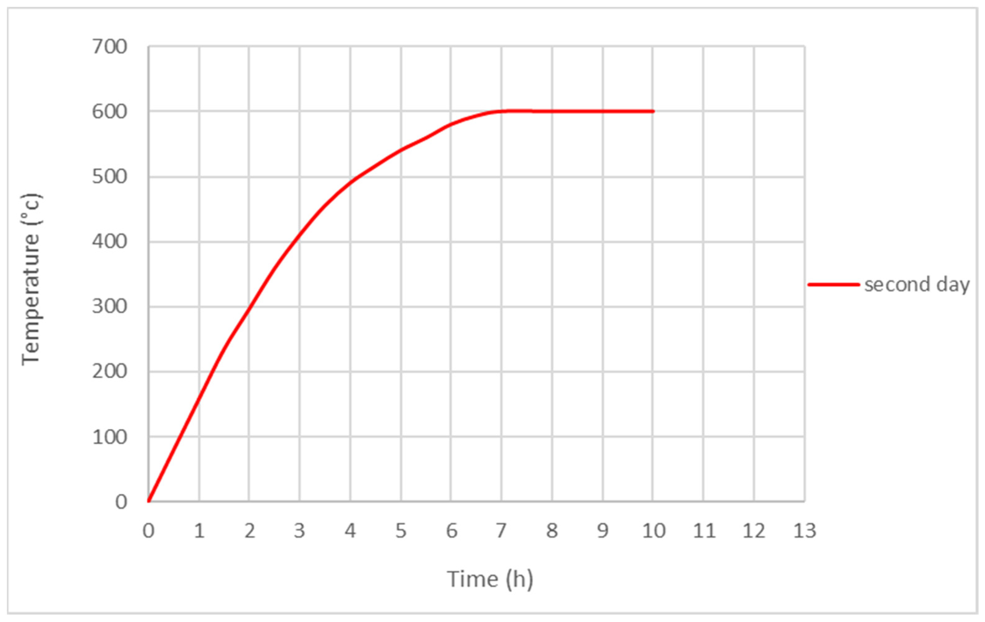
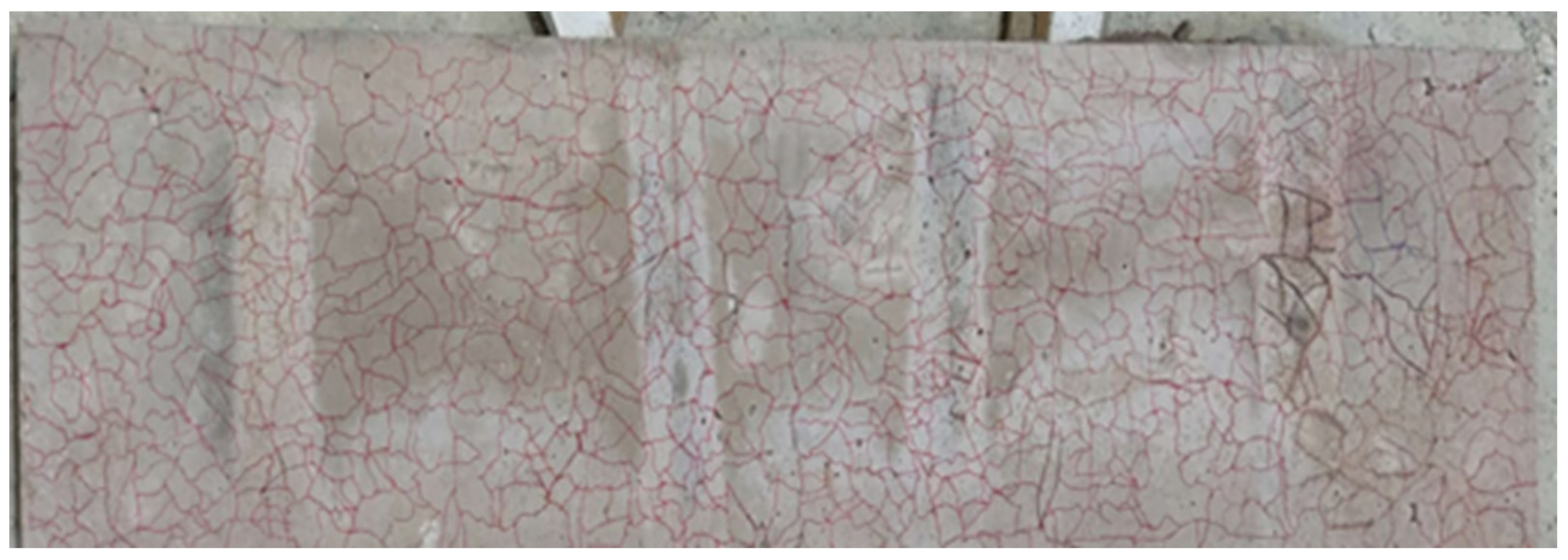
An oven with external dimensions of 1.7 m × 2.2 m × 0.7 m and internal dimensions of 2 m × 1.5 m × 0.6 m was utilized in the experiment. Seven out of the nine slabs and three cubes were exposed to a high temperature of 600 °C and maintained for three hours. After that, the slabs were rapidly cooled by immersion in a water tank for 15 min following the International Organization for Standardization (ISO) [47]. The temperature monitoring was performed by a digital temperature reader, as shown in Figure 5. The actual heating curve observed over the four days during which the samples were heated is presented in Figure 6. Accurate cracks were frequently observed due to the large change in temperature in a short time, as shown in Figure 7.

3.4. Test Matrix

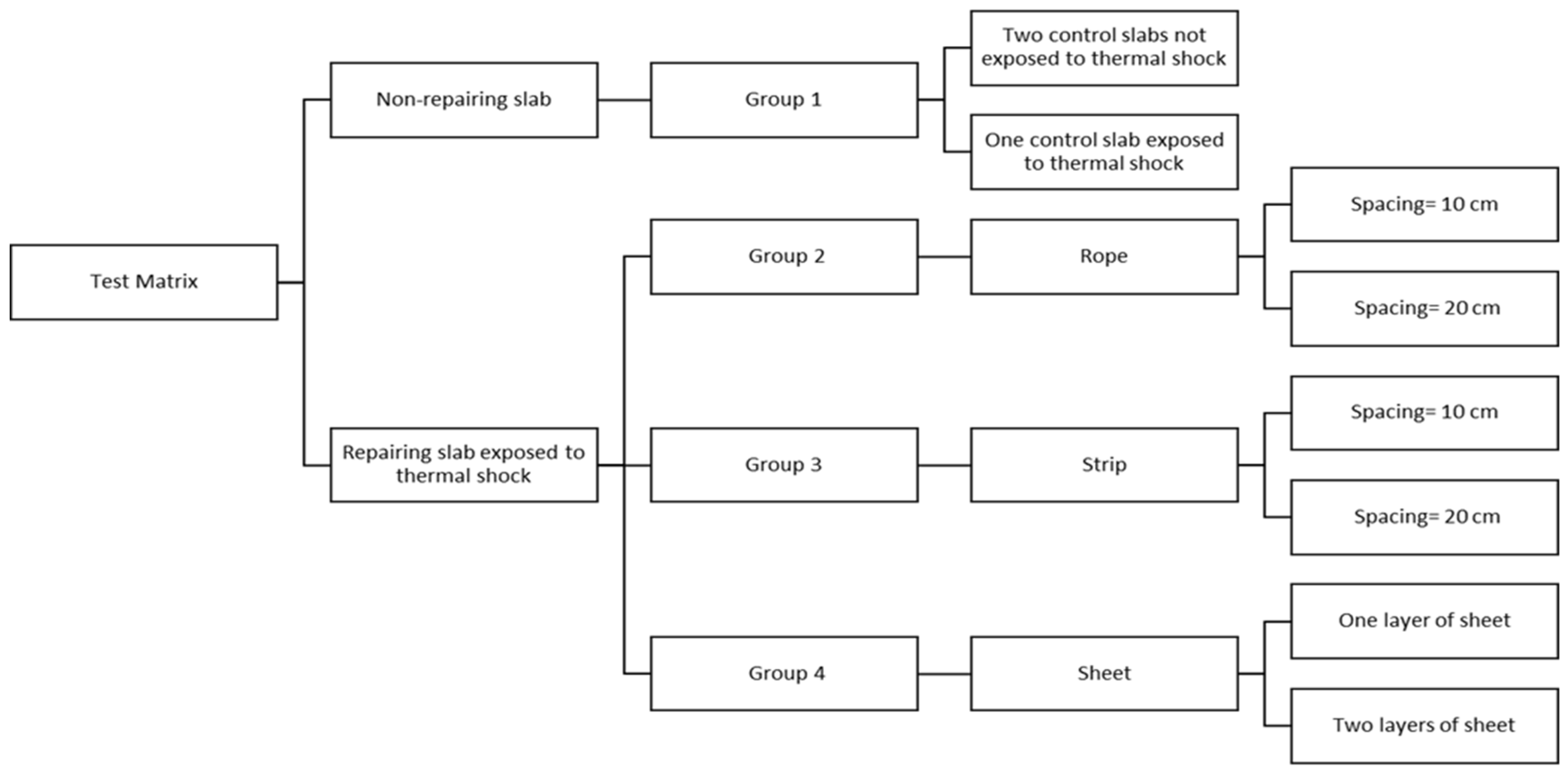
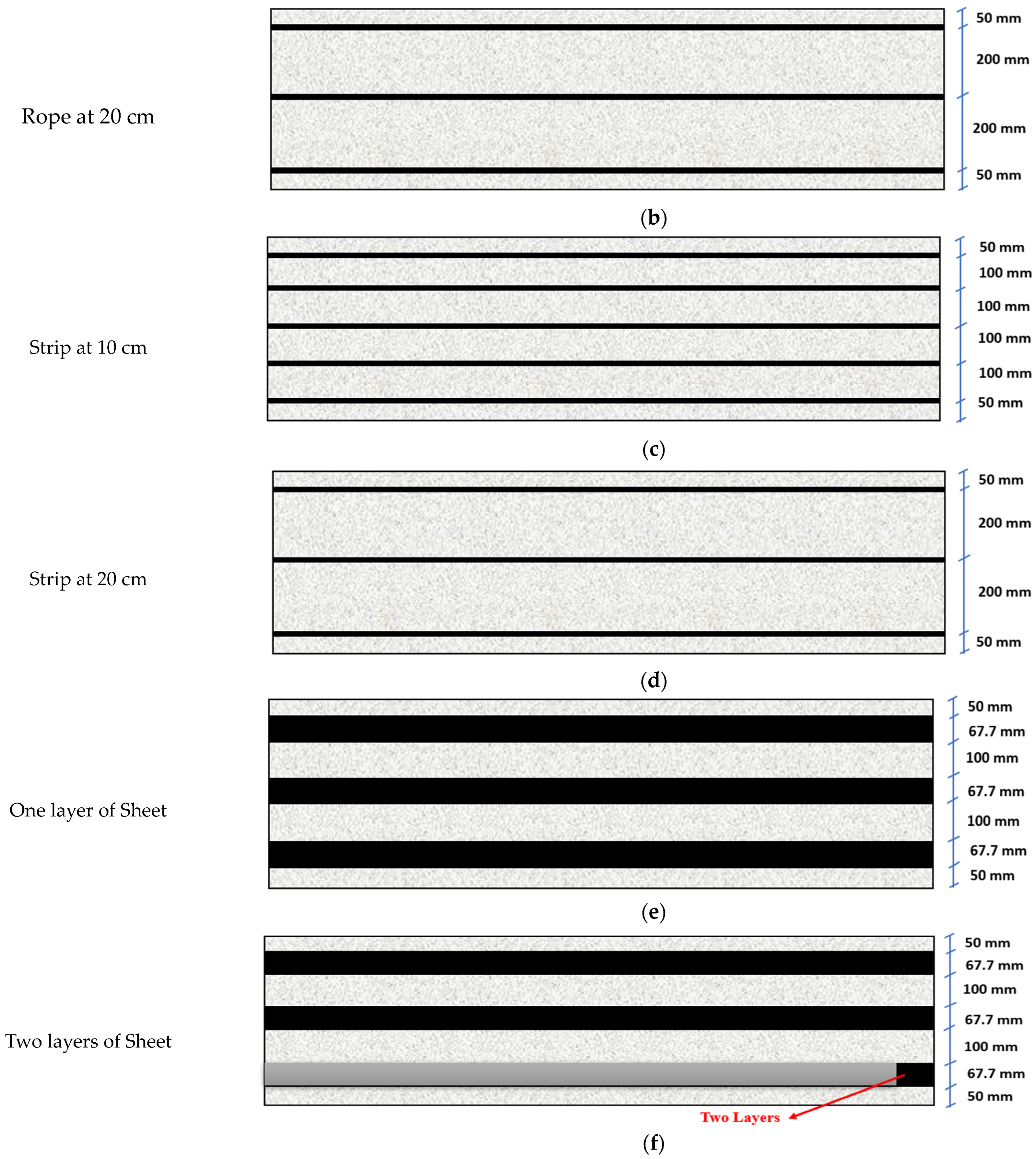
The experimental test matrix, as illustrated in Figure 8, was employed to assess the effectiveness of the NSM-CFRP technique for repairing RC one-way solid slabs subjected to thermal shock. Each repair configuration was tested using one sample. Symbols and indicators for the slabs can be found in Table 3, while details of the slabs are provided in Table 4. In addition, Figure 9 presents the repair configurations for slabs.

3.5. Installation of CFRP

3.5.1. CFRP Ropes and Strips Installation

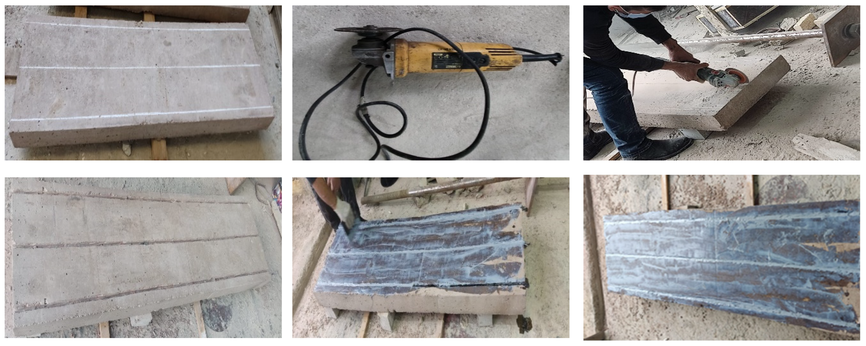
Initially, grooves were marked on the concrete surface with a width of 10 mm and a depth of 20 mm along the tensile surface of slab and then they were cut using an electric saw. After that, the grooves were cleaned by a vacuum cleaner of dust and dirt in preparation for filling the grooves with Sikandar®-330 epoxy to install ropes and strip in the grooves, anchoring them with epoxy and leveling the surface. The installation process for both ropes and strips are similar as shown in Figure 10, with the difference being that the ropes were immersed in Sikandar®-52 LP epoxy. Repair samples were left at laboratory temperature for 7 days to ensure full strength development, as recommended by the manufacturer.

3.5.2. CFRP Sheet Installation

A Carbon Fiber Reinforced Polymer (CFRP) sheet with a width of 66.7 mm was used along the tensile surface of the slab. The installation process of CFRP sheets involves surface roughening and cleaning to remove dust before applying Sikandar®-330 epoxy. The application of CFRP sheets is carried out externally using the same procedures mentioned in Section 3.5.1, as illustrated in Figure 11.

3.6. Test Setup

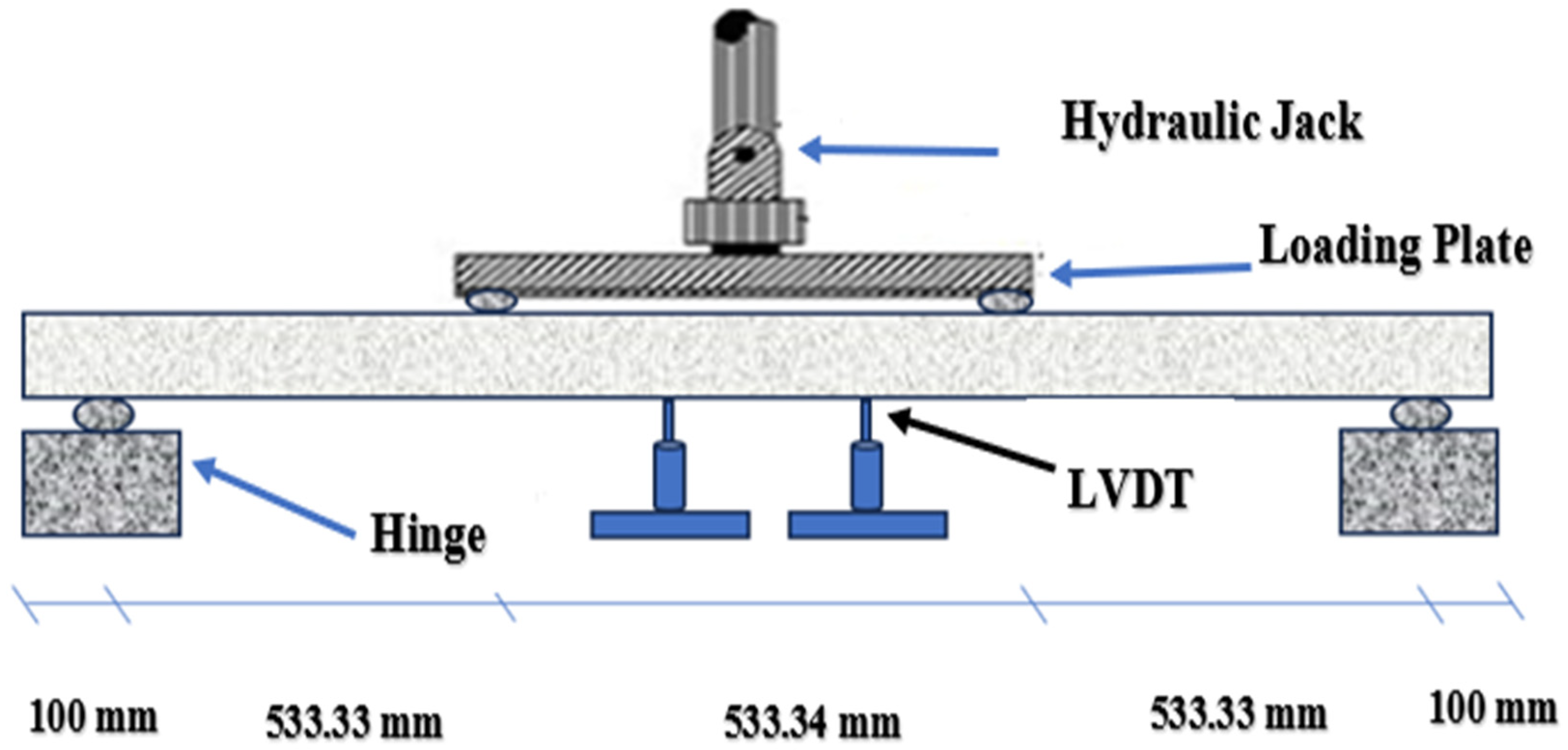
All RC slabs were tested under four loading points, with the slabs simply supported at 10 cm from the specimen ends. The second and third loading points were positioned at one-third of the free distance. The test was conducted using a hydraulic jack with a maximum capacity of 700 kN, where the load rate was applied at a constant rate of 5 kN/min. Additionally, two linear variable deflection transducers (LVDTs) were mounted in the middle band under the tensile surface of the slab to record deflection. Figure 12 shows the test setup.

4. Experimental Results

This section presents the results of the experimental work that was described in Section 3. Also, analyses of the results to investigate the effectiveness of the NSM-CFRP technique for all of the tested slabs compared to their respective control specimens are presented. Experimental observations included load-deflection curve, failure mode and stiffness, toughness, and deflection ductility factor for all specimens in detail.

4.1. Load-Deflection Curve

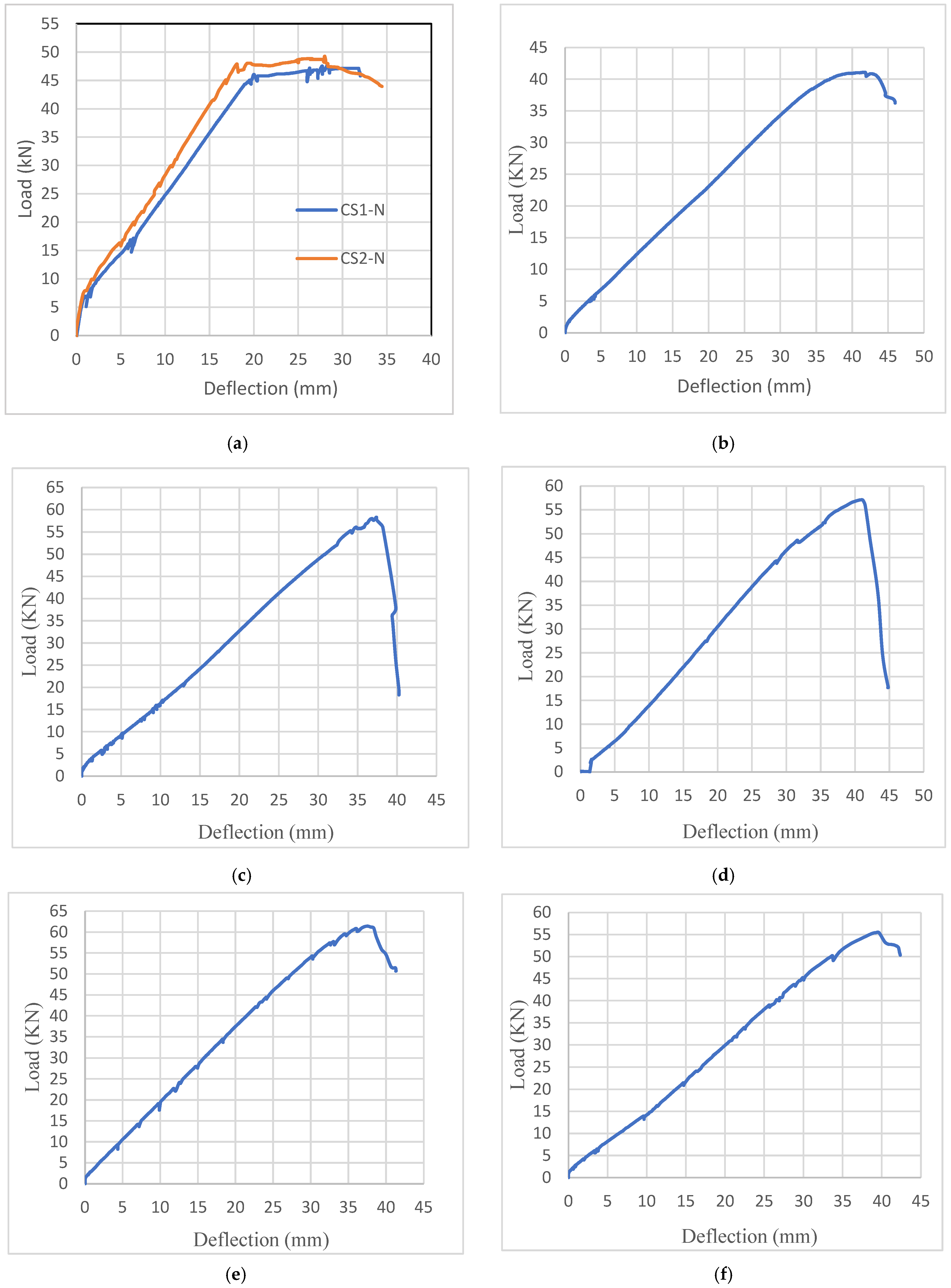
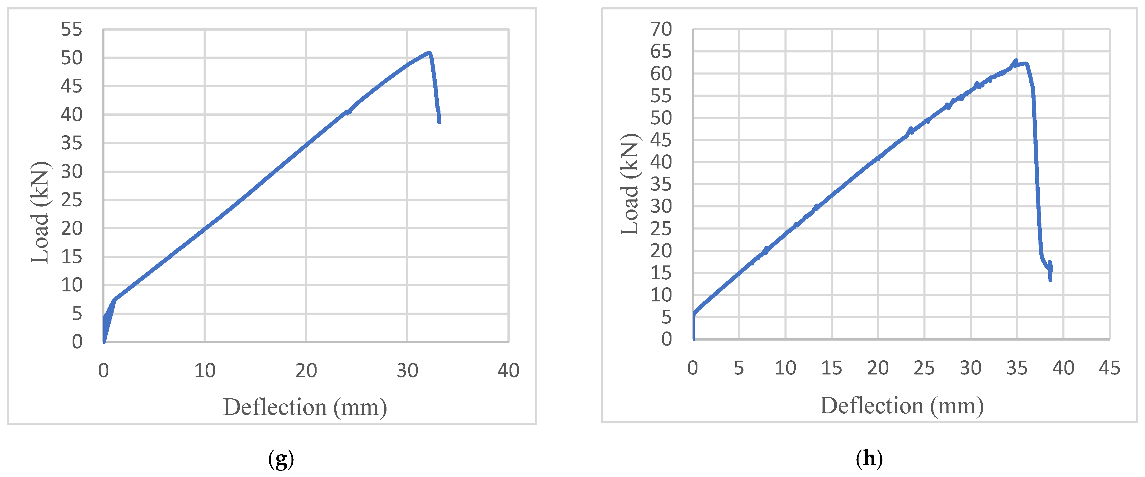
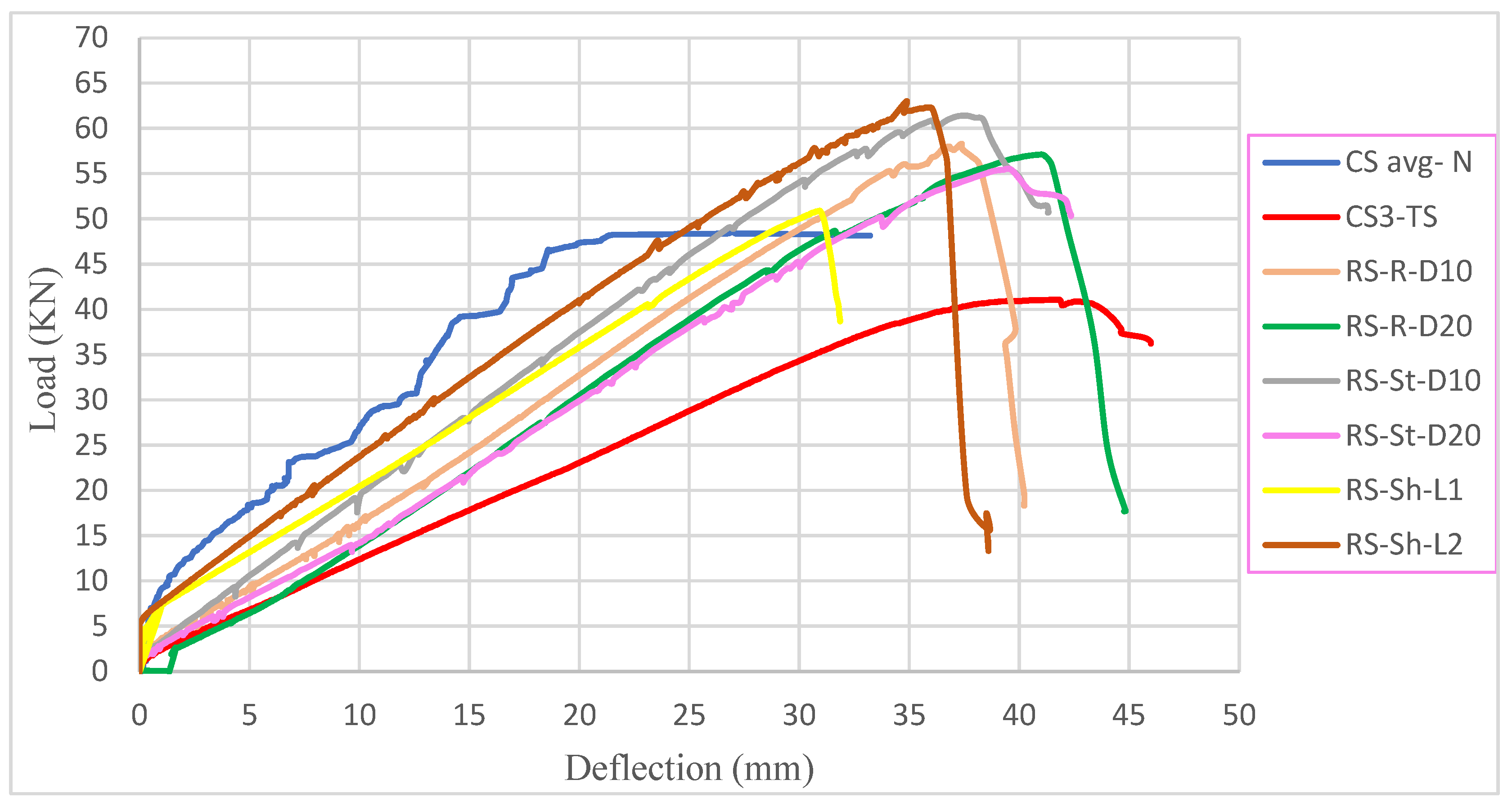
Figure 13 depicts load-deflection curves for all the slabs. These curves reveal three distinct phases of load-deflection behavior. The first phase, known as the pre-cracking phase, is characterized by an approximately linear relationship between load and deflection. The second phase is the pre-yielding stage, which is marked by a reduction in the slope of the load-deflection curve, indicating a decrease in the stiffness of the slab. This stage begins when the initial cracking of the section appears and concludes when the reinforcing steel exhibits inelastic behavior. The third phase is the fully plastic (nonlinear) stage, distinguished by the tension reinforcement reaching strain hardening. Table 5 presents various characteristics; these characteristics encompass the ultimate load, maximum deflection, failure mode, stiffness, toughness, and deflection ductility factor for all slabs. In addition, Table 6 presents the values compared to the CS3-TS sample.

4.2. Ultimate Load

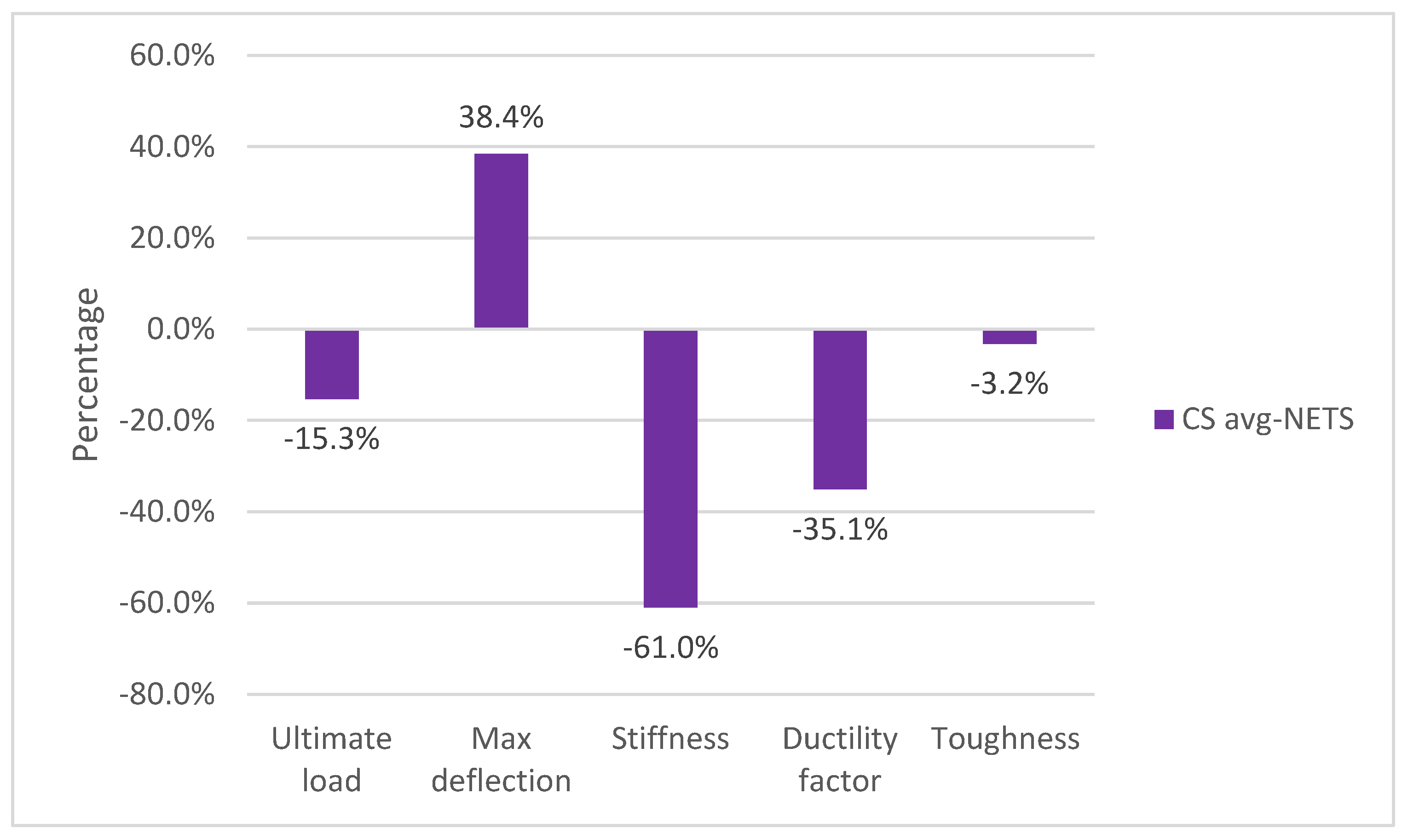
Referring to Figure 14 and Table 6, the ultimate load decreased due to thermal shock by 15.3% when compared to CSavg-N. However, slabs repaired using CFRP materials showed an increase in ultimate load ranging from 23.9% to 53.4% compared to CS3-TS. The maximum improvement in ultimate load was 53.4%, achieved using two sheets, while the minimum improvement was 23.9%, observed with using one sheet. Furthermore, the ultimate load of all slabs was restored after being exposed to thermal shock.

4.3. Maximum Deflection

Referring to Figure 14 and Table 6, the maximum deflection increases by 38.4% due to thermal shock when compared to CSavg-N. However, all slabs repaired using CFRP materials depict a decrease in maximum deflection ranging from 2.5% to 26.5% compared to CS3-TS. The highest improvement in deflection, 26.5%, was achieved using one sheet, while the minimum improvement was 2.5%, observed with using rope at a spacing of 20 cm. Furthermore, the maximum deflection of all repairing slabs was increased if compared to an unheated slab.

4.4. Failure Mode

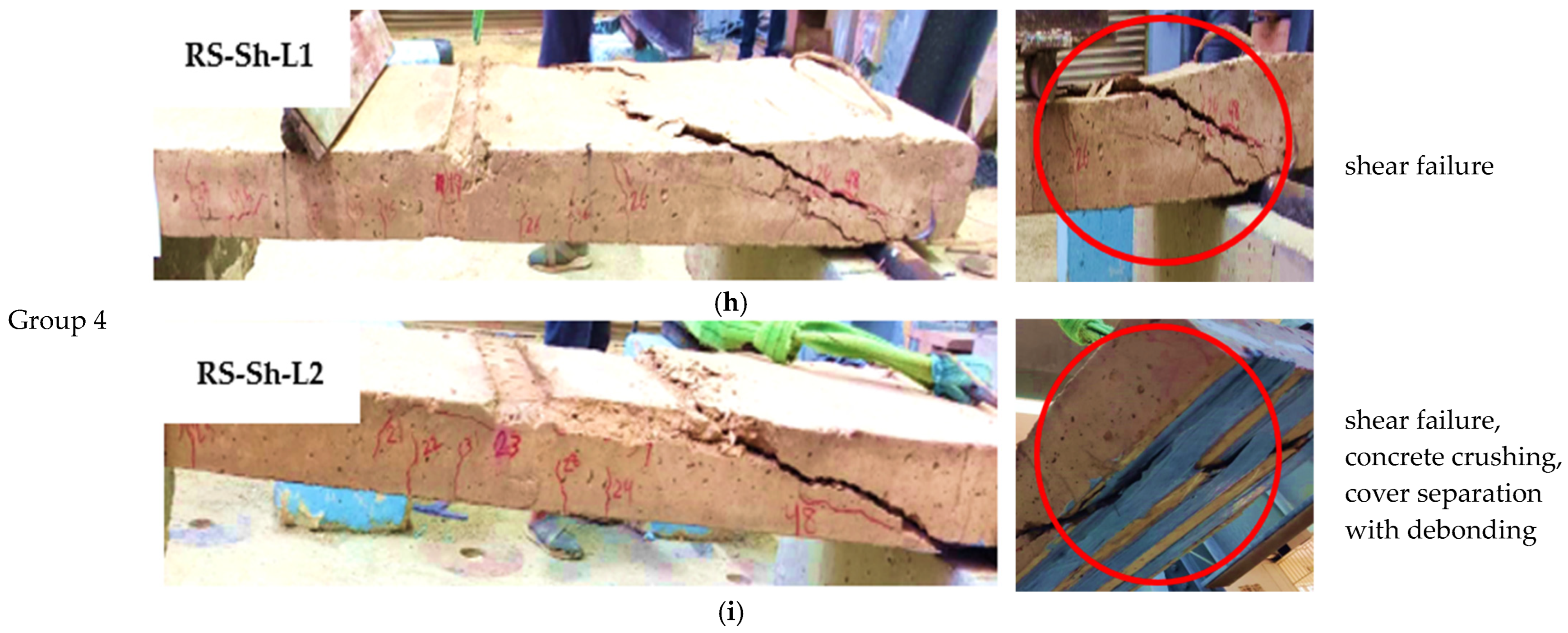
Many failure modes were observed in tested RC slabs samples such as flexure cracks, shear crack, debonding, concrete crushing, and cover separation, as shown in Figure 15. The failure mode of unheated control slabs was flexural failure. This flexural failure happened toward the midspan of the RC slab. As the external applied load increased, the additional cracks developed, as shown in Figure 15a,b. The failure mode of heated and repaired slab using the NSM-CFRP technique was shear failure as shown in Figure 15c–h; this can be explained when using CFRP, because the flexural capacity became greater than the shear capacity of the slab, and this led to brittle failure. Finally, the samples repaired using the CFRP-NSM technique exhibited shear cracks accompanied by the separation of the concrete cover, ultimately leading to debonding failure as shown in Figure 15d–h. This can be attributed to the increased stress concentration caused by CFRP confinement on the tensile surface. In addition, this phenomenon can be explained by the fact that the distance of the concrete cover, including the groove, was 20 mm; this distance led to increased tensile strength in that specific area resulting in elevated stress in the groove areas thereby increasing the probability of separation.

4.5. Stiffness

Stiffness determines how materials respond to externally applied loads and provides insight into the bond properties, as well as the mechanical and structural stability of an RC member. Mathematically, stiffness can be calculated by determining the slope of the linear portion of the load-deflection curve. Table 6 shows an increase in stiffness ranging from 32.7% to 65.5% compared to CS3-TS. The maximum improvement in stiffness was 65.5%, achieved using two layers of sheet, while the minimum stiffness was 32.7% observed with using strip at a spacing of 20 cm. It should be noted that the slabs repaired using CFRP-NSM were unable to restore the stiffness of the unheated slabs.

4.6. Ductility Factor

Ductility is the capacity of reinforced concrete members to undergo significant deflection before failure. This property can serve as an early warning of sudden failure and can also delay failure. The displacement ductility factor is calculated by dividing the maximum displacement value by the yielding displacement value. Table 6 shows a decrease in ductility ranging from 3.76% to 22.6% compared to CS3-TS. The maximum decrease in ductility was 22.6%, achieved using one layer of sheet, while the minimum decrease was 3.76%, observed with the use of strip and rope at a spacing of 20 cm. It should be noted that the slabs repaired using CFRP-NSM were unable to restore the ductility of the unheated slabs.

4.7. Toughness

Toughness is defined as the ability of a material to absorb energy and undergo plastic deformation without fracturing. Mathematically, toughness can be calculated as the area under the load-deflection curve by integrating the best fit to the load-deflection curve from zero to the maximum deflection. Table 6 shows an increase in toughness ranging from 0.4% to 28.6% compared to CS3-TS. The maximum improvement in toughness was 28.6%, achieved using strip at a spacing of 10 cm, while the minimum toughness was observed with using one layer of sheet. This is attributed to the repair with NSM-CFRP strips which enhances the slabs’ stiffness, enabling them to resist crack propagation more effectively. Consequently, a longer period to absorb more energy before reaching the fracture point is required.

5. Discussion of Experimental Results

5.1. Impact of Thermal Shock (at 600 ℃)

According to Figure 16, the ultimate load capacity of the slab exposed to thermal shock decreased by 15.3% and its maximum deflection increased by 38.4% compared to the unheated control slab. Also, the stiffness, ductility factor, and toughness of the slab exposed to thermal shock decreased by 61%, 35.1%, and 3.2%, respectively, compared to the unheated control slab. The decrease in these properties can be explained by the significant decrease in the compressive strength of the concrete, which is about 45.4%, and the decrease in the yielding strength of reinforcement steel by about 6.7% of its original values. These results are consistent with a study conducted by [8].

5.2. Impact of Spacing between CFRP Material

5.2.1. Impact of Spacing between Ropes

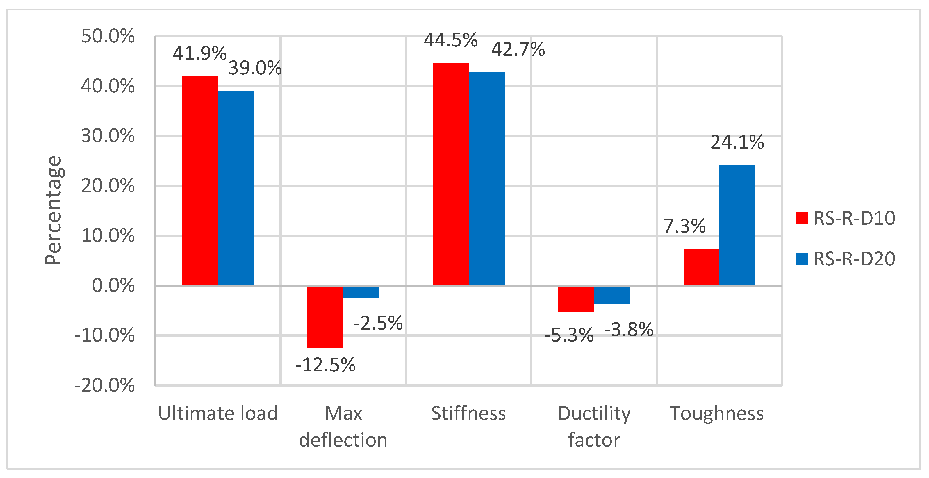
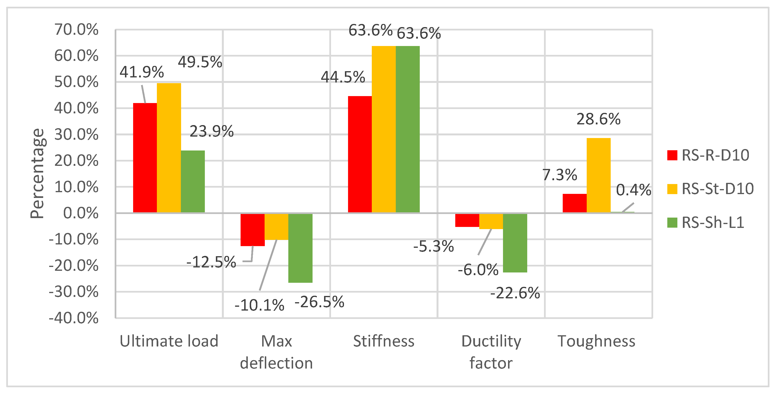
Figure 17 show characteristics of the load-deflection curve for slabs repaired with ropes; slab repaired at a distance of 10 cm showed better results than samples repaired at a distance of 20 cm compared to CS3 in terms of ultimate load, maximum deflection, and stiffness, improved by 41.9%, 12.5%, and 44.5%, respectively. While the ductility factor decreased by 8.5%, it should be noted that the maximum capacity at different distances was very close, and this is consistent with the results of the study conducted by [48].

5.2.2. Impact of Spacing between Strips

Figure 18 shows that samples repaired with strip at a distance of 10 cm showed better results than samples repaired at a distance of 20 cm at all parameters except for the ductility factor where the ultimate load, maximum deflection, stiffness, and toughness improved by 49.5%, 10.1%, 63.6%, and 28.6%, respectively. While the ductility factor decreased by 6%, it was observed that the maximum capacity at several distances was different on the opposite side when using rope and this is consistent with the results of [49].

5.3. Impact of Number of Sheet Layers

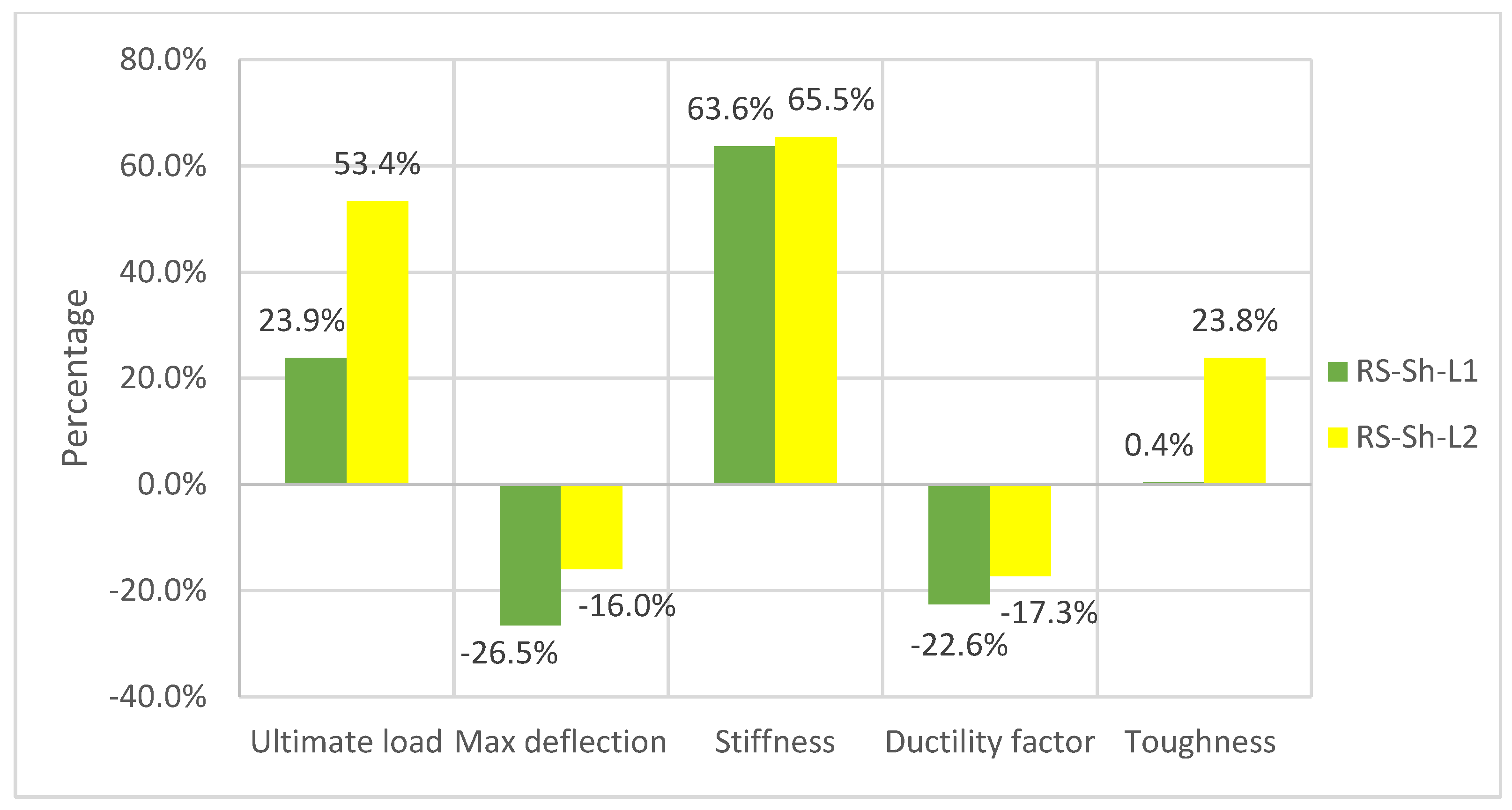
Figure 19 shows that the samples repaired with two layers of sheet exhibited better results than those repaired with one layer of sheet at all levels except for max deflection. The ultimate load, stiffness, and toughness for RS-Sh-L2 increased by 23.9%, 65.5%, and 23.8%, respectively, while the ductility factor decreased by 17.3%. Additionally, the max deflection for RS-Sh-L1 improved by 26.5%, which is consistent with the results of the study conducted by [50].

5.4. Impact of CFRP Form (Rope, Strip, Sheet)

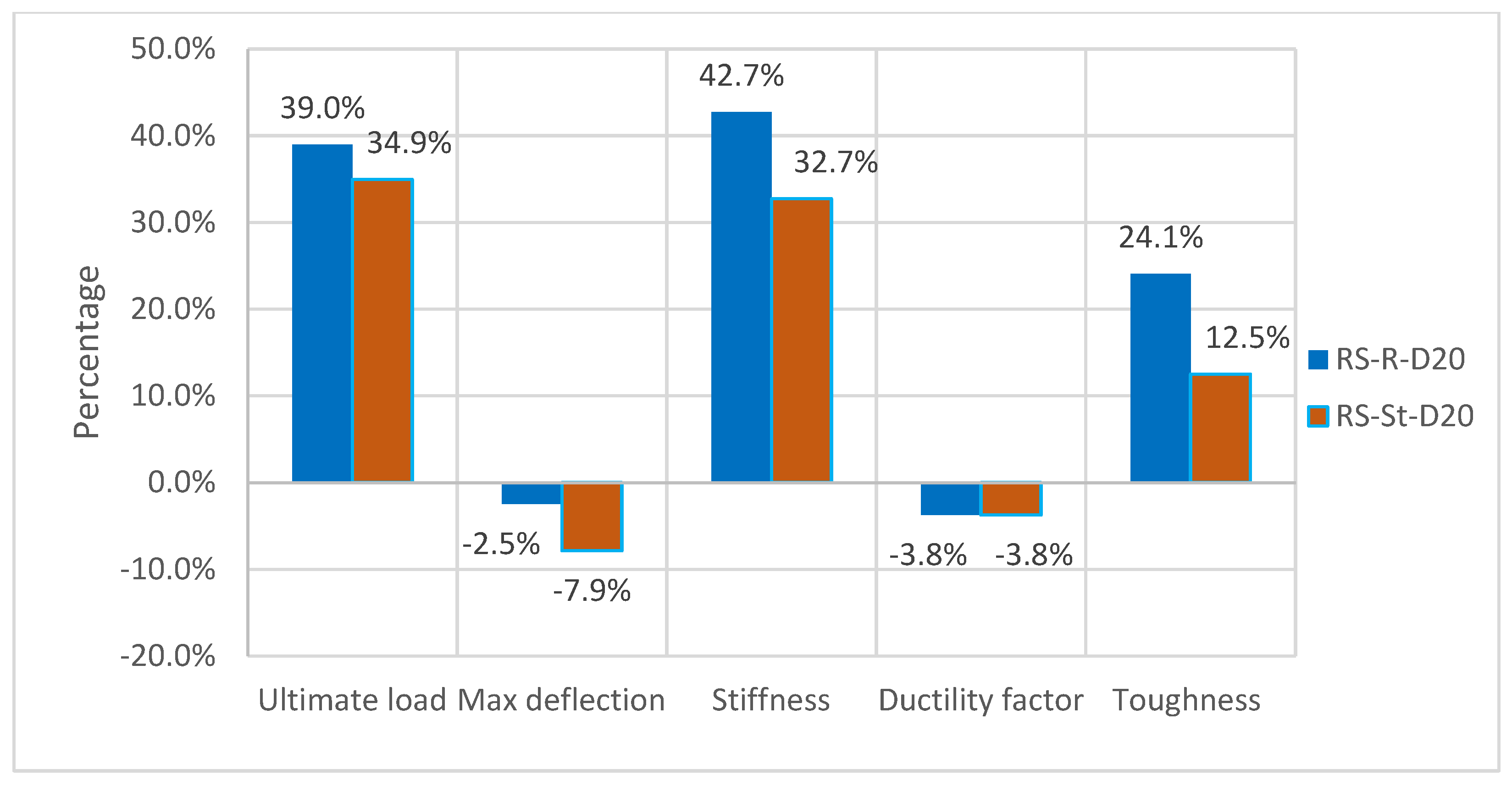
Stiffness and the ductility factor were close for strip and rope; regarding maximum deflection, the sheet achieved the most improvement by 26.5%. In addition, based on the results shown in Figure 20 and Figure 21, the performance of the materials changed when used at a distance of 20 cm. The rope exhibited better performance than the strips in terms of ultimate load, stiffness, and toughness, with improvements of 39%, 42.7%, and 24.1%, respectively. The ductility factor decreased equally by 3.8%. Regarding maximum deflection, the strip achieved the most improvement at 7.9%. This result is consistent with the results of the study conducted by [51].

6. Analytical Results

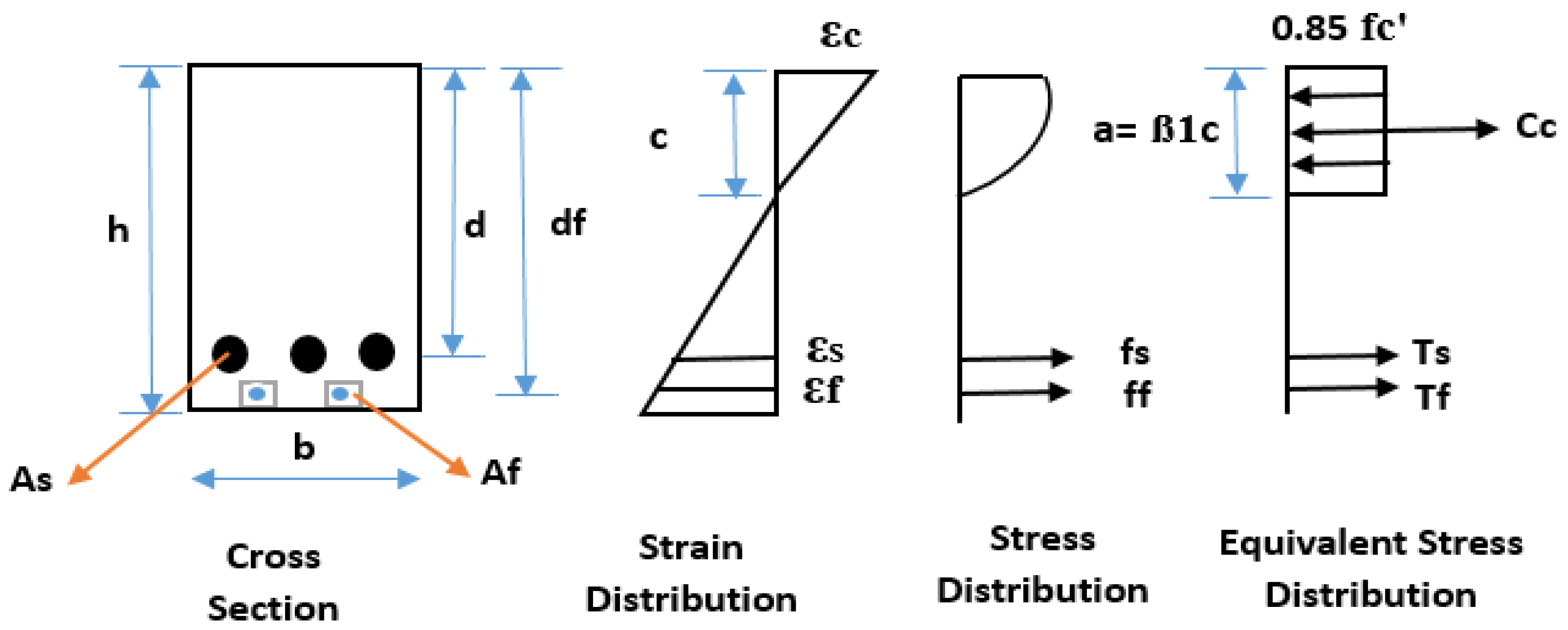
This section presents an analytical investigation of the repaired reinforced concrete one-way solid slabs exposed to thermal shock using the NSM-CFRP technique. The analysis is conducted in accordance with the design requirements outlined in ACI 318M-19 [46] and ACI 440.2R-17 [52]. To predict the flexural capacity, we utilized compatibility and equilibrium techniques as illustrated in Figure 22. Analytical deflection was calculated using the virtual work method, as described by Equation (2). It was computed for loads ranging from 1 kN to 64 kN. Also, Table 7 presents the experimental and theoretical results.
= L 3 L 2 M × m E c × I e
Shear strength in a structural member is determined by the average shear stress across the entire effective cross section. In cases where a member lacks shear reinforcement, the capacity for shear is carried by the concrete. Shear strengthening typically involves the installation of FRP systems with primary fibers oriented across potential shear cracks, often vertically or inclined within the slab. It is important to note that this research did not address shear strength enhancement. Consequently, the shear strength contribution from the FRP configuration was considered to be zero [53,54,55].
Theoretical results were compared with experimental results; the theoretical analysis can effectively estimate the flexural capacity of slabs when using various configurations of CFRP materials with identical areas. Notably, the analytical results were slightly higher than the experimental results, with percentage differences ranging from 0.07% to 12.88%. It is important to highlight that the ACI 440.2R-17 guidelines do not consider the length of CFRP materials in their recommendations. From what we can say, ACI 440.2R-17 [52] is considered a conservative guideline. As for calculating deflection values using the virtual work method, the control slabs showed a decrease ranging from 16.07% to 23.38%, while the repaired slabs showed a significant increase in max deflection ranging from 19.6 to 53.2%. This leads to the conclusion that the virtual work method may not be effective, especially for repaired slabs.

7. Numerical Analysis

7.1. Finite Element Method (FEM)

One method for addressing nonlinear simulations is the finite element method. ABAQUS software stands out as robust software in this domain and contains an extensive element library capable of modeling virtually any geometry. Furthermore, it offers a wide array of material models, making it suitable for simulating the behavior of various engineering materials such as concrete, metals, and polymers. Three-dimensional nonlinear finite element analyses using the ABAQUS software package was conducted to numerically simulate the repairing of RC one-way solid slabs exposed to thermal shock using CFRP [56,57,58]. The nonlinear finite element model established in ABAQUS software may include several thousand variables. To indicate the nonlinearity effect, the entire load must be divided into a series of load steps. One (kn) of the load was applied at each step. Additionally, ABAQUS updates the solution at the conclusion of each step and incorporates it for the following step to account for nonlinearity.

7.2. Model Description

The slabs were simulated in ABAQUS software, beginning with the creation of the slab part. The slab had a cross section measuring 1800 mm in length, 500 mm in width, and 100 mm in thickness. Following the slab, the steel reinforcement and CFRP rope were modeled as one-dimensional elements, while the CFRP strip and sheet were modeled as shell elements. Subsequently, the support plate and loading bar were designed to match the actual test setup, both having a length of 500 mm and being made of steel. Material properties for each part will be detailed in the next section. After assigning the material properties, the parts were assembled using the assembly module. Five instances of steel reinforcement were created in the longitudinal direction, and four instances in the transverse direction.
Next, the step module was defined as 1 s to reduce computation time. All models had the same step size, and all interactions were defined as tie constraints, except for the interaction between concrete and reinforcement, which was specified as an embedded region due to the assumption of a full bond with no slipping. Boundary conditions were then applied, and the load was applied to the nodes along the centerline of the two support plates under the slab to simulate roller and pin support. The load, being deflection-controlled rather than load-controlled, gradually increased linearly. This approach was chosen to avoid generating velocity and acceleration after exceeding the maximum load, as observed in load-controlled scenarios. Moving on to the mesh module, considering the slabs as the most critical part, a 25 mm cubic mesh with a hexagonal configuration was utilized with the aim of achieving accurate results and effectively visualizing cracks. Finally, in the output request, both field and history output were modified. One request was made for measuring load as an integrated output section, and two for measuring deflection. Subsequently, the job was created before submission.
Numerical results from the FEM simulation were compared with the experimental results and these results include the ultimate load, maximum deflection, and failure mode.

7.2.1. Parts

Based on the experimental work discussed in Section 3, this model consists of five main parts, namely concrete, steel reinforcement, support plate, loading plate, and CFRP form (rope, strip, and sheet). Table 8 shows the parts details.

7.2.2. Materials

  • Concrete
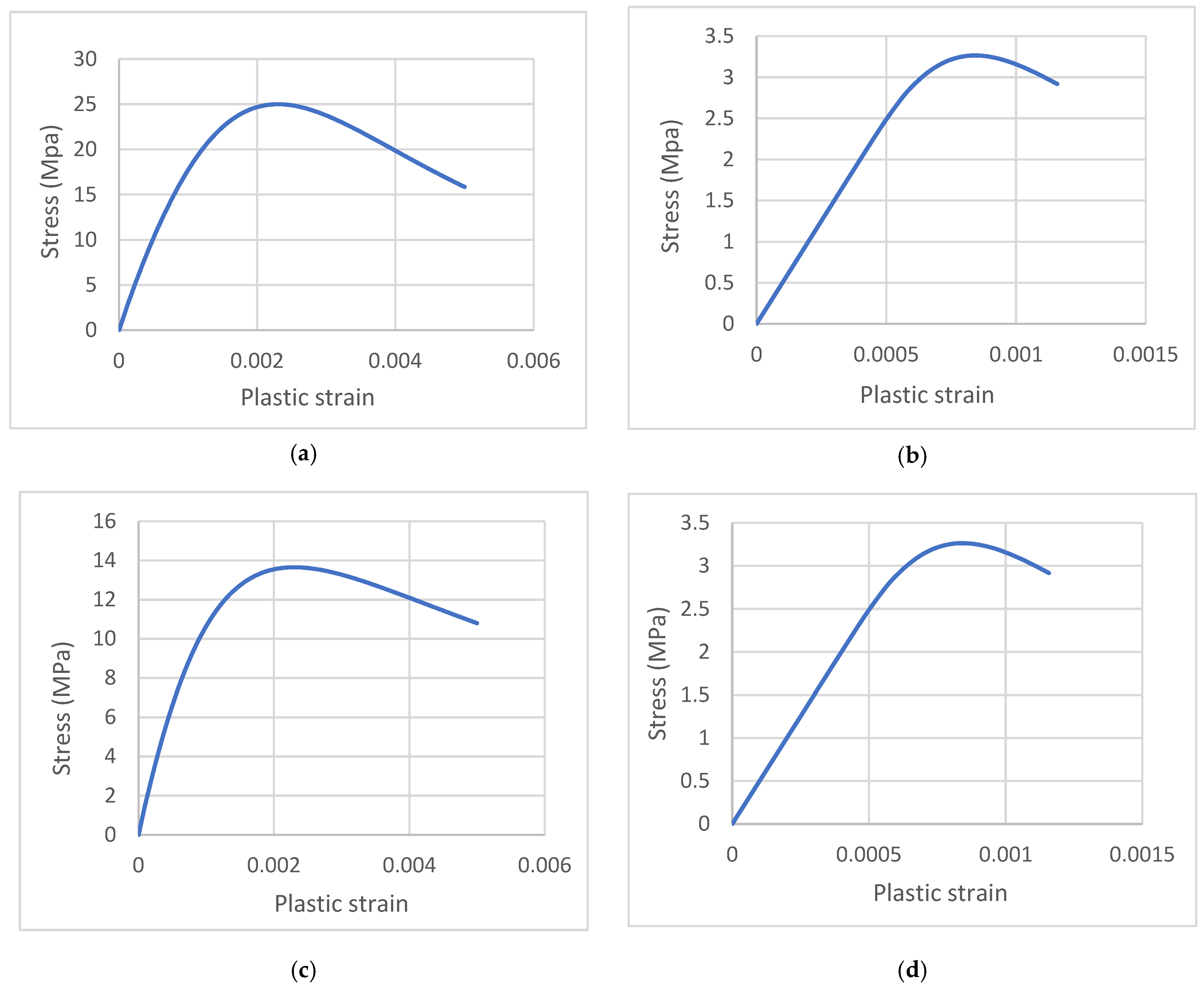
Tsai’s constitutive model equations were used to predict the compressive and tensile behavior of both unheated and heated slabs. The compressive strength was 25 MPa for the unheated slab and 13.6 MPa for the heated slab. The modulus of elasticity was 23,500 MPa for the unheated slab and 5000 MPa for the heated slab following (EN 1994-1-2) code [59]. Additionally, the Poisson’s ratio was 0.2. The compression and tension stress–strain curves are shown in Figure 23.
  • Concrete Damage Parameter (CDP)
Tension and compression damage parameters (dc, dt) with values ranging from zero to one can be used to represent the reduction in concrete stiffness and strength caused by tensile cracking and compressive crushing. The ABAQUS User’s Manual [60] states that the undamaged content is represented by zero and the entire loss of strength is represented by one. To compute the evolution of damage variables for concrete under uniaxial compression and stress, many formulae have been provided in the literature. The following equations were used to determine the two damage variables in this analysis.
d c = 1 σ c f c o
d t = 1 σ t f c t
where
  • σc: Concrete compressive stress along the descending stress–strain curve.
  • f′ co: Concrete compressive stress at the peak point.
  • σt: Concrete tensile stress along the descending stress–strain curve.
  • f′ ct: Concrete tensile stress at the peak point.
  • Steel reinforcement
The linear elastic–perfectly plastic model was used to represent the stress–strain relationships of steel reinforcement; the yielding stress of the steel reinforcement employed in the modeling was 537 MPa, the modulus of elasticity was 200 GPa, the mass density was 7.8 × 10⁹ kg/mm3, and the Poisson’s ratio was 0.3.
  • CFRP
The CFRP materials were modeled as linear elastic up to failure, with an ideal bond assumed between the CFRP material and the concrete surface using a tie connection [46]. Characteristics of CFRP materials for the elastic stage are listed in Table 9.

7.3. Numerical Results

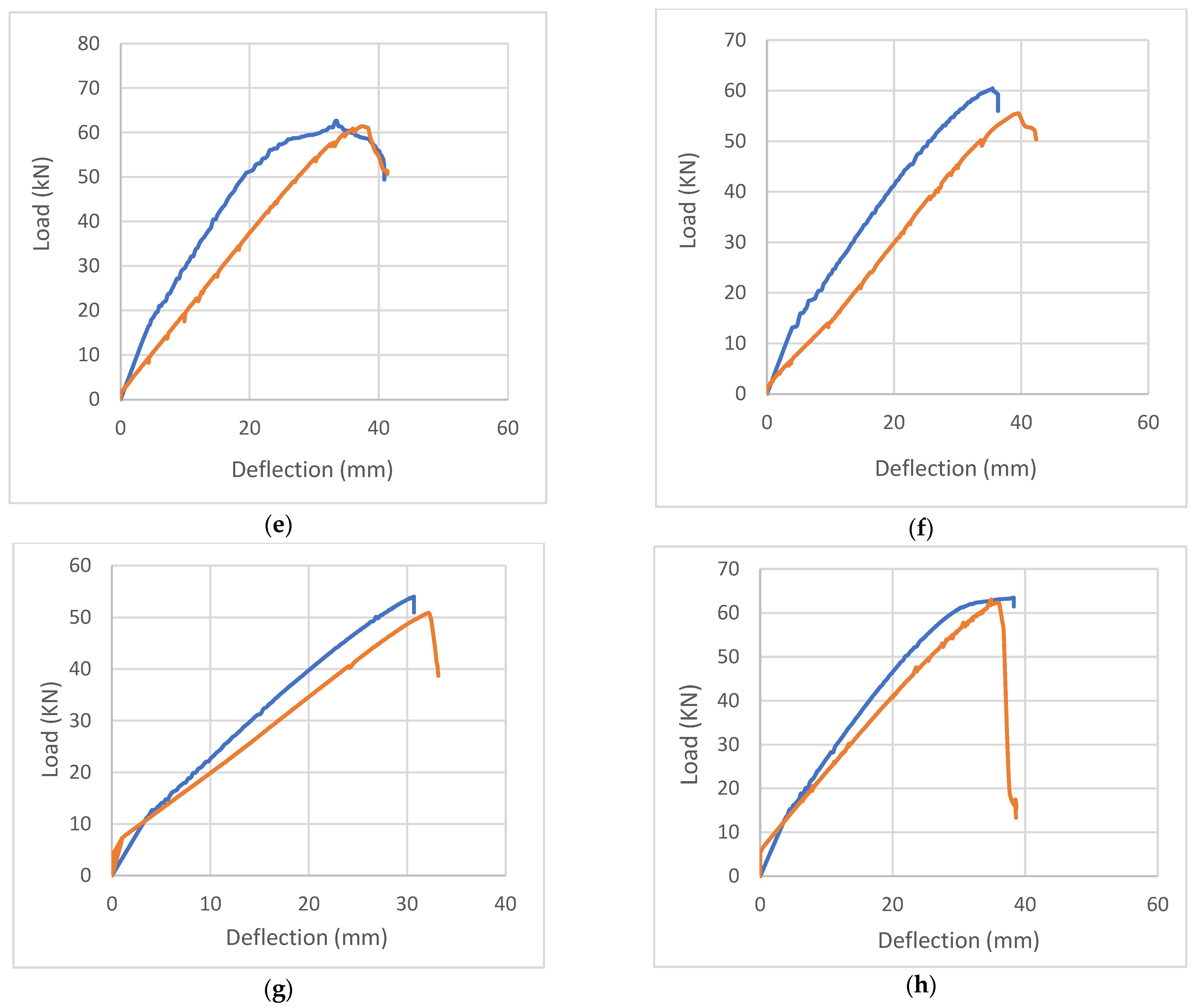
The load-deflection curves depicted in Figure 24 show a good match with the experimental results. Table 10 presents a summary of numerical results. Additionally, Table 10 displays the percentage of change in the numerical results when compared to the experimental and theoretical results, with regards to the ultimate load and maximum deflection, respectively.
The results presented in Table 11 demonstrate a clear similarity between the results obtained from the nonlinear finite element (FE) model with experimental results. The disparities observed in the ultimate load are relatively minor, ranging between 0.71% to 10.38% when compared to the experimental results. Additionally, the numerical results demonstrate a good match; a slight reduction was observed in the maximum deflection, ranging from 0.95% to 14.16%, if compared with the experimental results.
On the other hand, when comparing the numerical results with the theoretical results, a discrepancy became evident concerning the ultimate load; the percentage of difference ranged from −4.36% to 11.45%. Similarly, in terms of maximum deflection, there was a substantial difference, spanning from −35.81% to 20.87%. Several factors can account for these disparities. For instance, theoretical calculations often rely on linear assumptions, which may not accurately represent the behavior under large deformations. Additionally, theoretical calculations may assume simplified boundary conditions that do not precisely reflect real-world load and deflection constraints. Furthermore, numerical approximations also contribute to these differences.
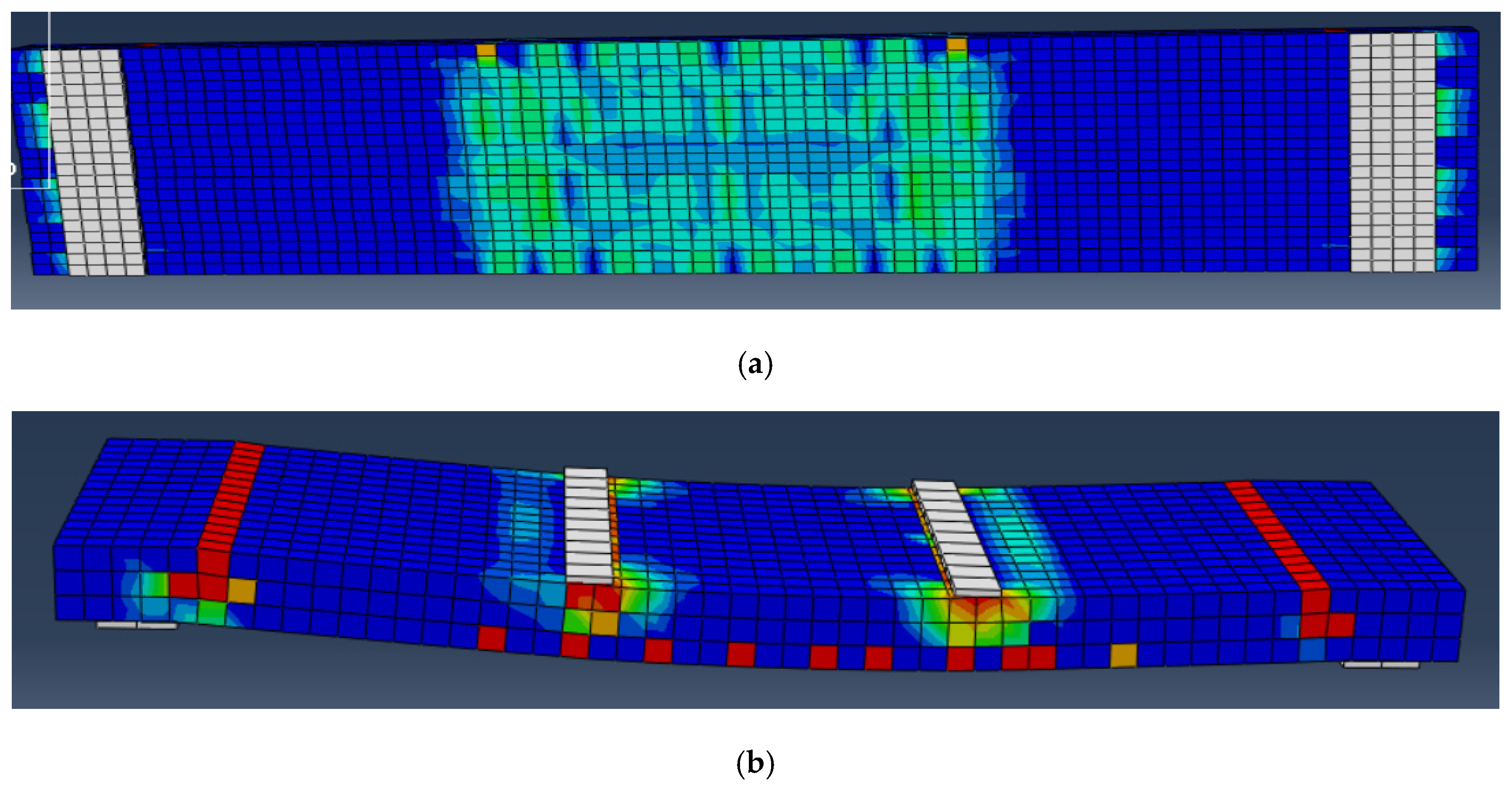
The calibration results showed good agreement with the experimental results in terms of failure mode. Figure 25 shows the failure of the slabs; the repaired slabs failed to shear where two cracks developed due to the symmetry of the setup, which is the theoretically expected failure mode. In an experimental test, a small detail led to imperfect symmetry leading to the crack developing only on one side alone and one main wide crack and some small cracks.

8. Conclusions

Based on the experimental and analytical results, the following conclusions can be drawn:
  • Exposure to thermal shock has an obvious and significant effect on mechanical properties. This effect is characterized by a decline in parameters such as compressive strength, elasticity, load capacity, toughness, and ductility.
  • Extensive cracks were observed to propagate across the concrete surface of thermally shocked slabs without spalling, a phenomenon attributed to water evaporation.
  • The use of carbon fiber-reinforced polymer showed a noteworthy enhancement of the mechanical and structural properties of thermally shocked slabs, particularly in terms of load capacity, stiffness, toughness, and deflection.
  • All rehabilitated slabs exhibited the ability to recover their initial capacity before being subjected to thermal shock. However, the repaired slabs were unable to regain their original stiffness, likely due to internal cracks.
  • The utilization of carbon fiber-reinforced polymer led to a reduction in the ductility property of thermally shocked slabs, possibly due to the brittle nature of the material.
  • This research demonstrated that decreasing the spacing between carbon fiber-reinforced polymer materials resulted in improved load capacity: 2.9% for ropes and 14.6% for strips. Similarly, stiffness increased by 1.8% for ropes and 29.9% for strips, with positive effects extending to deflection reduction. Similar enhancements were observed with an increase in the number of layers.
  • Thermal shock may have a negative effect on the failure mode of the slab. In this research, it shifted from flexural failure to brittle shear failure.
  • The theoretical analysis consistently demonstrated slightly superior performance compared to the experimental results. Therefore, it is advisable to incorporate a safety factor when evaluating the load capacity of a repaired slab.
  • The finite element method stands out as a potent tool for replicating experimental tests, and its results can be extrapolated to investigate scenarios that have not been examined experimentally, requiring significant cost and time.

9. Recommendation and Future Work

Based on previous research and to the best of the authors’ knowledge, there are knowledge gaps regarding the exposure of reinforced structural members to thermal shock and techniques for repairing them. For instance, a few studies have been conducted on thermally shocked beams and repairing them using CFRP, while even fewer have been carried out on slabs. Accordingly, we recommend conducting further research on concrete elements after exposure to thermal shock. Some potential future work may include the following:
  • No studies have investigated the effect of using various types of FRP, such as GFRP.
  • Temperature may play different roles in response and behavior; therefore, an in-depth understanding of the effect of temperature values and their correlations is needed.
  • Conducting more research on various structural elements such as columns and two-way solid slabs.
  • Using FRP with different configurations, such as orientation (45° and 90°), sheet widths (100 and 200 mm), CFRP rope and strip with different lengths, and more than one layer (2 and 3).

Author Contributions

Conceptualization, M.A.-J.; methodology, A.A.; validation, M.S. and A.A.; formal analysis, M.A.-J.; investigation, M.S.; resources, M.A.-J.; data curation, M.S.; writing—original draft preparation, M.S.; writing—review and editing, A.A. and M.A.-J.; visualization, M.A.-J. and A.A.; supervision, M.A.-J.; project administration, M.A.-J. and A.A. All authors have read and agreed to the published version of the manuscript.

Funding

The authors appreciate the financial support provided by the academic research deanship at the University of Jordan. Also, this study is supported via funding from Prince sattam bin Abdulaziz University project number (PSAU/2024/R/1445).

Data Availability Statement

The article includes all the research data.

Conflicts of Interest

The authors declare no conflicts of interest.

References

  1. Khan, Q.U.Z.; Ahmad, A.; Raza, A.; Labibzadeh, M.; Iqbal, M. Structural Performance of One-Way Slabs Reinforced with Steel and Polypropylene Fibers. J. Kejuruter. 2021, 33, 193–203. [Google Scholar] [CrossRef]
  2. Abdel-Jaber, M.; Shatarat, N.; Katkhuda, H.; Al-Zu’bi, H.; Al-Nsour, R.; Alhnifat, R.; Al-Qaisia, A. Influence of Temperature on Shear Behavior of Lightweight Reinforced Concrete Beams Using Pozzolana Aggregate and Expanded Polystyrene Beads. CivilEng 2023, 4, 1036–1051. [Google Scholar] [CrossRef]
  3. Faris, N.; Zayed, T.; Abdelkader, E.M.; Fares, A. Corrosion assessment using ground penetrating radar in reinforced concrete structures: Influential factors and analysis methods. Autom. Constr. 2023, 156, 105130. [Google Scholar] [CrossRef]
  4. Abdel-Jaber, M.; Shatarat, N.; El-Nimri, R. Influence of Using Expanded Polystyrene Beads on the Density and Compressive Strength of Hardened Concrete. Civ. Eng. Arch. 2023, 11, 3599–3611. [Google Scholar] [CrossRef]
  5. de Carvalho, E.F.T.; Neto, J.T.d.S.; Junior, P.R.R.S.; Maciel, P.d.S.; Fransozo, H.L.; Bezerra, A.C.d.S.; de Gouveia, A.M.C. Influence of cooling methods on the residual mechanical behavior of fire-exposed concrete: An experimental study. Materials 2019, 12, 3512. [Google Scholar] [CrossRef]
  6. Fehérvári, S. Effect of cooling methods on the residual properties of concrete exposed to elevated temperature. Results Eng. 2022, 16, 100797. [Google Scholar] [CrossRef]
  7. Abramowicz, M.; Kowalski, R. The influence of short time water cooling on the mechanical properties of concrete heated up to high temperature. J. Civ. Eng. Manag. 2005, 11, 85–90. [Google Scholar] [CrossRef]
  8. Obaidat, Y.; Barham, W.; Obeidat, R. Repair of thermally shocked reinforced concrete beams using near-surface mounted—Carbon fiber reinforced polymers ropes and strips. Constr. Build. Mater. 2023, 366, 130201. [Google Scholar] [CrossRef]
  9. Knyziak, P.; Kowalski, R.; Krentowski, J.R. Fire damage of RC slab structure of a shopping center. Eng. Fail. Anal. 2019, 97, 53–60. [Google Scholar] [CrossRef]
  10. Abdullah, A.; Al-Khazraji, S. Structural Behavior of High Strength Laced Reinforced Concrete One Way Slab Exposed to Fire Flame. Civ. Eng. J. 2019, 5, 2747–2761. [Google Scholar] [CrossRef]
  11. Abdel-Jaber, M.; Al-Nsour, R.; Shatarat, N.; Katkhuda, H.; Al-Zu’bi, H. Thermal Effect on the Flexural Performance of Lightweight Reinforced Concrete Beams Using Expanded Polystyrene Beads and Pozzolana Aggregate. Eng. Sci. 2023, 27, 1029. [Google Scholar] [CrossRef]
  12. Al-Zu’Bi, M.; Fan, M.; Al Rjoub, Y.; Ashteyat, A.; Al-Kheetan, M.J.; Anguilano, L. The effect of length and inclination of carbon fiber reinforced polymer laminates on shear capacity of near-surface mounted retrofitted reinforced concrete beams. Struct. Concr. 2021, 22, 3677–3691. [Google Scholar] [CrossRef]
  13. Al-Zu’Bi, M.; Fan, M.; Anguilano, L. Advances in bonding agents for retrofitting concrete structures with fibre reinforced polymer materials: A review. Constr. Build. Mater. 2022, 330, 127115. [Google Scholar] [CrossRef]
  14. Al-Zu’bi, H.; Abdel-Jaber, M.; Katkhuda, H. Flexural Strengthening of Reinforced Concrete Beams with Variable Compressive Strength Using Near-Surface Mounted Carbon-Fiber-Reinforced Polymer Strips [NSM-CFRP]. Fibers 2022, 10, 86. [Google Scholar] [CrossRef]
  15. Al-Zu’Bi, M.; Fan, M.; Anguilano, L. Composites Part C: Open Access Parametric investigation of flexural performance of concrete prisms retrofitted with near-surface mounted FRP bars. Compos. Part C Open Access 2023, 12, 100421. [Google Scholar] [CrossRef]
  16. Wang, Q.; Li, T.; Zhu, H.; Su, W.; Hu, X. Bond enhancement for NSM FRP bars in concrete using different anchorage systems. Constr. Build. Mater. 2020, 246, 118316. [Google Scholar] [CrossRef]
  17. Alexander, M.; Beushausen, H. Durability, service life prediction, and modelling for reinforced concrete structures—Review and critique. Cem. Concr. Res. 2019, 122, 17–29. [Google Scholar] [CrossRef]
  18. Abas Golham, M.; Al-Ahmed, A.H.A. Behavior of GFRP reinforced concrete slabs with openings strengthened by CFRP strips. Results Eng. 2023, 18, 101033. [Google Scholar] [CrossRef]
  19. Mohammed, S.A.; Said, A.M.I. Analysis of concrete beams reinforced by GFRP bars with varying parameters. J. Mech. Behav. Mater. 2022, 31, 767–774. [Google Scholar] [CrossRef]
  20. Sabbaghian, M.; Kheyroddin, A. Flexural strengthening of RC one-way slabs with high-performance fiber-reinforced cementitious composite laminates using steel and GFRP bar. Eng. Struct. 2020, 221, 111106. [Google Scholar] [CrossRef]
  21. Ayash, N.M.; Abd-Elrahman, A.M.; Soliman, A.E. Repairing and strengthening of reinforced concrete cantilever slabs using Glass Fiber–Reinforced Polymer (GFRP) wraps. Structures 2020, 28, 2488–2506. [Google Scholar] [CrossRef]
  22. Tan, K.Y.; Tumialan, G.; Nanni, A. Evaluation of Externally Bonded Cfrp Systems for the Strengthening of Rc Slabs. Fibre-Reinf. Polym. Reinf. Concr. Struct. 2003, 2, 417–426. [Google Scholar] [CrossRef]
  23. Niu, H.; Vasquez, A.; Karbhari, V.M. Effect of material configuration on strengthening of concrete slabs by CFRP composites. Compos. Part B Eng. 2005, 37, 213–226. [Google Scholar] [CrossRef]
  24. Elgabbas, F.; El-Ghandour, A.A.; Abdelrahman, A.A.; El-Dieb, A.S. Different CFRP strengthening techniques for prestressed hollow core concrete slabs: Experimental study and analytical investigation. Compos. Struct. 2010, 92, 401–411. [Google Scholar] [CrossRef]
  25. Saeed, Y.M.; Aules, W.A.; Rad, F.N. Flexural strengthening of RC columns with EB-CFRP sheets and NSM-CFRP rods and ropes. Compos. Struct. 2022, 301, 116236. [Google Scholar] [CrossRef]
  26. Seleem, M.; Megahed, F.; Badawy, A.; Sharaky, I. Performance of NSM and EB methods on the flexural capacity of the RC beams strengthened with reinforced HSC layers. Structures 2023, 56, 104950. [Google Scholar] [CrossRef]
  27. Hosseini, M.R.M.; Dias, S.J.E.; Barros, J.A.O. Behavior of one-way RC slabs flexurally strengthened with prestressed NSM CFRP laminates—Assessment of influencing parameters. Compos. Struct. 2020, 245, 112259. [Google Scholar] [CrossRef]
  28. Aghamohammadi, R.; Nasrollahzadeh, K.; Mofidi, A.; Gosling, P. Reliability-based assessment of bond strength models for near-surface mounted FRP bars and strips to concrete. Compos. Struct. 2021, 272, 114132. [Google Scholar] [CrossRef]
  29. Chen, J.; Teng, J. Shear capacity of FRP-strengthened RC beams: FRP debonding. Constr. Build. Mater. 2003, 17, 27–41. [Google Scholar] [CrossRef]
  30. Al-Saadi, N.T.K.; Mohammed, A.; Al-Mahaidi, R.; Sanjayan, J. A state-of-the-art review: Near-surface mounted FRP composites for reinforced concrete structures. Constr. Build. Mater. 2019, 209, 748–769. [Google Scholar] [CrossRef]
  31. Zhang, R.; Xue, X. A predictive model for the bond strength of near-surface-mounted FRP bonded to concrete. Compos. Struct. 2021, 262, 113618. [Google Scholar] [CrossRef]
  32. Sharaky, I.A.; Torres, L.; Comas, J.; Barris, C. Flexural response of reinforced concrete (RC) beams strengthened with near surface mounted (NSM) fibre reinforced polymer (FRP) bars. Compos. Struct. 2014, 109, 8–22. [Google Scholar] [CrossRef]
  33. Al-Nsour, R.; Abdel-Jaber, M.; Ashteyat, A.; Shatarat, N. Flexural repairing of heat damaged reinforced concrete beams using NSM-BFRP bars and NSM-CFRP ropes. Compos. Part C Open Access 2023, 12, 100404. [Google Scholar] [CrossRef]
  34. Ceroni, F.; Pecce, M.; Bilotta, A.; Nigro, E. Bond behavior of FRP NSM systems in concrete elements. Compos. Part B Eng. 2012, 43, 99–109. [Google Scholar] [CrossRef]
  35. da Costa, L.M.; Pires, T.A.d.C.; Silva, J.J.R. Shear strengthening of fire-damaged reinforced concrete beams using NSM CFRP laminates. Eng. Struct. 2023, 287, 116175. [Google Scholar] [CrossRef]
  36. De Lorenzis, L.; Teng, J.G. Near-surface mounted FRP reinforcement: An emerging technique for strengthening structures. Compos. Part B Eng. 2007, 38, 119–143. [Google Scholar] [CrossRef]
  37. Adheem, A.H.; Kadhim, M.M.; Jawdhari, A. Parametric study and improved capacity model for RC beams strengthened with side NSM CFRP bars. Structures 2022, 39, 1118–1134. [Google Scholar] [CrossRef]
  38. Jacobs, R.R.; Williams, C.S. Evaluation of flexural strengthening methods for beams with simulated deterioration using spike-anchored FRP externally bonded sheets and near-surface-mounted strips. Compos. Struct. 2023, 305, 116463. [Google Scholar] [CrossRef]
  39. Al-Rousan, R.Z. Anchored CFRP ropes for flexural capacity recovering of thermally damaged RC one-way slabs. Alex. Eng. J. 2023, 76, 757–774. [Google Scholar] [CrossRef]
  40. Al-Rousan, R. Behavior of strengthened concrete beams damaged by thermal shock. Mag. Civ. Eng. 2020, 2, 93–107. [Google Scholar]
  41. Assad, M.; Hawileh, R.A.; Abdalla, J.A. Modeling the behavior of CFRP-strengthened RC slabs under fire exposure. Procedia Struct. Integr. 2022, 42, 1668–1675. [Google Scholar] [CrossRef]
  42. Hamiruddin, N.A.; Razak, R.A.; Muhammad, K.; Zahid, M.Z.A.M. Repair of heat damaged reinforced concrete slab with High Strength Fibre Reinforced Concrete materials. In IOP Conference Series: Earth and Environmental Science; Institute of Physics Publishing: Bristol, UK, 2018. [Google Scholar] [CrossRef]
  43. Abdel-Jaber, M.; Abdel-Jaber, M.; Katkhuda, H.; Shatarat, N.; Sulaiman, A.; El-Nimri, R. Influence of Stirrup Spacing on the Strengthening and Rehabilitating of RC T-beams Using Near-Surface Mounted Carbon-Fiber-Reinforced Polymer Strips. Fibers 2022, 10, 103. [Google Scholar] [CrossRef]
  44. Gao, W.-Y.; Hu, K.-X.; Dai, J.-G.; Dong, K.; Yu, K.-Q.; Fang, L.-J. Repair of fire-damaged RC slabs with basalt fabric-reinforced shotcrete. Constr. Build. Mater. 2018, 185, 79–92. [Google Scholar] [CrossRef]
  45. Al-Rousan, R. Influence of opening sizes on the flexural behavior of heat-damaged reinforced concrete slabs strengthened with CFRP ropes. Case Stud. Constr. Mater. 2022, 17, e01464. [Google Scholar] [CrossRef]
  46. ACI 318M-19; Building Code Requirements for Structural Concrete. American Concrete Institute: Farmington Hills, MI, USA, 1989; Volume 2007.
  47. ISO, ISO 834-1:1999; Fire-Resistance Tests—Elements of Building Construction—Part 1, General Requirements. International Standard Organization: Geneva, Switzerland, 1999.
  48. Al-Khreisat, A.; Abdel-Jaber, M.; Ashteyat, A. Shear Strengthening and Repairing of Reinforced Concrete Deep Beams Damaged by Heat Using NSM–CFRP Ropes. Fibers 2023, 11, 35. [Google Scholar] [CrossRef]
  49. Houda, A.; Benbouras, M.; Zedira, H.; Redjel, B.; Lefilef, L. The Influence of Spacing Between Cfrp Strips on. Construction 2022, 13, 73–86. [Google Scholar]
  50. Al-Khafaji, A.; Salim, H. Flexural strengthening of RC continuous t-beams using CFRP. Fibers 2020, 8, 41. [Google Scholar] [CrossRef]
  51. Saadah, M.; Ashteyat, A.; Murad, Y. Shear strengthening of RC beams using side near surface mounted CFRP ropes and strips. Structures 2021, 32, 380–390. [Google Scholar] [CrossRef]
  52. ACI Committee 440; Guide for the Design and Construction of Externally Bonded FRP Systems for Strengthening Concrete ACI 440.2R-17. American Concrete Institute: Farmington Hills, MI, USA, 2017; p. 110.
  53. Pellegrino, C.; Modena, C. Fiber-reinforced polymer shear strengthening of reinforced concrete beams: Experimental study and analytical modeling. ACI Struct. J. 2006, 103, 720–728. [Google Scholar] [CrossRef]
  54. Sim, J.; Kim, G.; Park, C.; Ju, M. Shear strengthening effects with varying types of FRP materials and strengthening methods. Am. Concr. Institute ACI Spec. Publ. 2005, SP-230, 1665–1679. [Google Scholar] [CrossRef]
  55. Beramly, M.; Abdel-Jaber, M.; Katkhuda, H.; Shatarat, N.; Al-Diseet, M. Shear Strengthening and Rehabilitating of Reinforced Concrete T-Beams Using Externally Carbon Fiber Reinforced Polymer Sheets. J. Appl. Eng. Sci. 2022, 20, 498–510. [Google Scholar] [CrossRef]
  56. Yu, T.; Teng, J.; Wong, Y.; Dong, S. Finite element modeling of confined concrete-II: Plastic-damage model. Eng. Struct. 2010, 32, 680–691. [Google Scholar] [CrossRef]
  57. Abeje, Y.K. Numerical Study to Investigate the Effect of CFRP Sheet on Ductility of Reinforced Concrete Slab. Int. J. Eng. Res. Technol. 2022, 11, 142–153. [Google Scholar]
  58. Assad, M.; Hawileh, R.; Abdalla, J. Finite Element Simulation of FRP-Strengthened Thin RC Slabs. J. Compos. Sci. 2022, 6, 263. [Google Scholar] [CrossRef]
  59. CEN member, EN 1994-1-2 (2005); Eurocode 4: Design of Composite Steel and Concrete Structures—Part 1-2: General Rules—Structural Fire Design. ECS, European Committee for Standardization: Brussels, Belgium, 2011; Volume 1. (In English)
  60. Systèmes, D. Abaqus 6.12 analysis user’s manual: Prescribed conditions, constraints & interactions. Abaqus 2012, 5, 831. [Google Scholar]
Figure 1. CFRP materials: (a) rope; (b) strip; (c) sheet.
Fibers 12 00018 g001
Figure 2. Slabs fabricated.
Fibers 12 00018 g002
Figure 3. Slab dimensions.
Fibers 12 00018 g003
Figure 4. Reinforcement detail: (a) longitudinal direction; (b) transverse direction.
Fibers 12 00018 g004
Figure 5. Thermal shock process.
Fibers 12 00018 g005
Figure 6. Heating curve.
Fibers 12 00018 g006
Figure 7. Crack developed by thermal shock.
Fibers 12 00018 g007
Figure 8. Test matrix.
Fibers 12 00018 g008
Figure 9. Repair configuration: (a) RS-R-D10; (b) RS-R-D20; (c) RS-St-D10; (d) RS-St-D20; (e) RS-Sh-L1; (f) RS-Sh-L2.
Fibers 12 00018 g009aFibers 12 00018 g009b
Figure 10. CFRP ropes installation.
Fibers 12 00018 g010
Figure 11. CFRP sheet installation.
Fibers 12 00018 g011aFibers 12 00018 g011b
Figure 12. Test setup.
Fibers 12 00018 g012
Figure 13. Load-deflection curve of slabs: (a) CS1-N; CS2-N; (b) CS3-ETS; (c) RS-R-D10; (d) RS-R-D20; (e) RS-St-D10; (f) RS-St-D20; (g) RS-Sh-L1; (h) RS-Sh-L2.
Fibers 12 00018 g013aFibers 12 00018 g013b
Figure 14. Load-deflection curve for all specimens.
Fibers 12 00018 g014
Figure 15. Failure mode of slabs: (a) CS1-N; (b) CS2-N; (c) CS 3-ETS; (d) RS-R-D10; (e) RS-R-D20; (f) RS-St-D10; (g) RS-St-D20; (h) RS-Sh-L1; (i) RS-Sh-L2.
Fibers 12 00018 g015aFibers 12 00018 g015bFibers 12 00018 g015c
Figure 16. Percentage of the impact of thermal shock on the characteristics of the load-deflection curve.
Fibers 12 00018 g016
Figure 17. Percentage of the impact of the spacing between the ropes on the characteristics of the load-deflection curve.
Fibers 12 00018 g017
Figure 18. Percentage of the impact of the spacing between the strips on the characteristics of the load-deflection curve.
Fibers 12 00018 g018
Figure 19. Percentage of the impact of the number of sheet layers on the characteristics of the load-deflection curve.
Fibers 12 00018 g019
Figure 20. Percentage of the impact of CFRP form (rope, strip, and sheet) on the characteristics of the load-deflection curve at 10 cm.
Fibers 12 00018 g020
Figure 21. Percentage of the impact of CFRP form (rope and strip) on the characteristics of the load-deflection curve at 20 cm.
Fibers 12 00018 g021
Figure 22. Stress and strain compatibility of concrete rectangular cross sections strengthened by NSM-CFRP under flexural capacity.
Fibers 12 00018 g022
Figure 23. Stress–strain diagram: (a) compressive curve for unheated slab; (b) tensile curve for unheated slab; (c) compressive curve for heated slab; (d) tensile curve for heated slab.
Fibers 12 00018 g023
Figure 24. Load-deflection curve for experimental vs. numerical results: (a) CS avg-N; (b) CS3-TS; (c) RS-R-D10; (d) RS-R-D20; (e) RS-St-D10; (f) RS-St-D20; (g) RS-Sh-L1; (h) RS-Sh-L2.
Fibers 12 00018 g024aFibers 12 00018 g024b
Figure 25. Failure mode for slabs using FE model: (a) CS1-N; CS2-N; (b) CS 3-ETS; (c) RS-R-D10; (d) RS-R-D20; (e) RS-St-D10; (f) RS-St-D20; (g) RS-Sh-L1; (h) RS-Sh-L2.
Fibers 12 00018 g025aFibers 12 00018 g025b
Table 1. Characteristics of CFRP materials.
CharacteristicsCFRP Type
RopeStripSheet
Elasticit Modulus (GPa)240165230
Tensile Strength (MPa)400031004900
Fiber Density (g/cm3)1.821.61.8
Cross Section (mm2)2837.5167/m width
Elongation at Break≥1.6%≥1.7%1.7%
Table 2. Characteristics of epoxy.
CharacteristicsEpoxy Type
Sikandar®-330Sikandar®-52 LP
Packaging5 kg A + B (light grey)4 kg A + B (Yellowish brownish)
Density (Kg/L) 1.3 ± 0.11.06
Tensile Strength (MPa)3027
Elastic Modulus (MPa)45001100
Mixing RatioA:B = 4:1 part by weightA:B = 2:1 part by weight and by volume
Elongation at Break0.9%1.9%
Table 3. Symbol indicators.
SymbolIndicator
CSControl Slab
RSRepairing Slab exposed to thermal shock
NNatural
TSThermal Shock
RRope
StStrip
ShSheet
D10Distance = 10 cm
D20Distance = 20 cm
L1One Layer
L2Two Layers
Table 4. Slabs detail.
NO of
Sample
LabeledExposure to
Thermal Shock
Type of FRPParameterRepair Configuration
1CS1-NNonNonNonN/A
2CS2-NNonNonNonN/A
3CS3-TSExposedNonNonN/A
4RS-R-D10ExposedRopeSpacing (10 cm)Rope at 10 cm
5RS-R-D20ExposedRopeSpacing (20 cm)Rope at 20 cm
6RS-St-D10ExposedStripSpacing (10 cm)Strip at 10 cm
7RS-St-D20ExposedStripSpacing (20 cm)Strip at 20 cm
8RS-Sh-L1ExposedSheetOne LayerOne layer of sheet
9RS-Sh-L2ExposedSheetTwo LayersTwo layers of sheet
Table 5. Summary of slabs results.
NameUltimate Load
(KN)
Max Deflection
(mm)
Stiffness
(KN/mm)
Ductility FactorToughness
(KN.mm)
* Failure Mode
** CS avg-N48.533.222.862.051200.58FF
CS3-TS41.0845.981.11.331162.60SF and F-S
RS-R-D1058.340.231.591.261247.02SF and CC
RS-R-D2057.0944.841.571.281442.48SF and CS
RS-St-D1061.4241.331.81.251494.92SF, CC, CS, and DF
RS-St-D2055.4342.361.461.281308.06SF, CS, and DF
RS-Sh-L150.8833.81.81.031167.3SF
RS-Sh-L26338.631.821.11439.19SF, CC, CS, and DF
* FF: flexural failure; SF: shear failure; F-S: flexural-shear crack; CC: concrete crushing; CS: cover separation; DF: debonding failure. ** CS avg-N is average of CS1-N and CS2-N.
Table 6. Results compared with CS3-TS.
NameUltimate Load (%)Max
Deflection (%)
Stiffness (%)Ductility
Factor (%)
Toughness (%)
CSavg-N18.1−27.816054.13.23
RS-R-D1041.9−12.544.5−5.37.3
RS-R-D2039−2.542.7−3.824.1
RS-St-D1049.5−10.163.6−628.6
RS-St-D2034.9−7.932.7−3.812.5
RS-Sh-L123.9−26.563.6−22.60.4
RS-Sh-L253.4−1665.5−17.2323.8
Table 7. Comparison between theoretical and experimental results.
Name of SlabPn Exp (KN)Pn Theo (KN)Difference Ratio
Compared with
(Pn Exp) (%)
Deflection
Exp (mm)
Deflection
Theo (mm)
Difference Ratio
Compared with
(Deflection Exp) (%)
CSavg-N48.551.466.133.2226.38−20.59
CS3-TS41.0842.834.2645.9838.59−16.07
RS-R-D1058.365.8112.8840.2354.7636.12
RS-R-D2057.0959.624.4344.8453.6319.6
RS-St-D1061.4264.444.9241.3357.6939.58
RS-St-D2055.4358.816.142.3652.0722.92
RS-Sh-L150.8854.116.3533.841.450.03
RS-Sh-L26363.050.0738.6359.1853.2
Table 8. Parts details.
PartModeling SpaceElement TypeShape
Concrete3DC3D8R: An 8-node linear brick, reduced integration, hourglass control.Solid
Steel bars3DT3D2: A 2-node linear 3D truss.Wire
Load plate3DC3D8R: An 8-node linear brick, reduced integration, hourglass control.Solid
Support plate3DC3D8R: An 8-node linear brick, reduced integration, hourglass control.Solid
Rope3DT3D2: A 2-node linear 3D truss.Wire
Strip3DS4R: A 4-node doubly curved thin or thick shell, reduced integration, hourglass control, finite membrane strains.Shell
Sheet3DS4R: A 4-node doubly curved thin or thick shell, reduced integration, hourglass control, finite membrane strains.Shell
Table 9. Characteristics of CFRP materials for the elastic stage.
MaterialDensityElastic Modulus (Mpa)Poisson’s Ratio
Rope1.82 × 10−9 240,0000.2
Strip1.6 × 10−9 165,0000.2
Sheet1.8 × 10−9 230,0000.2
Table 10. Numerical results.
Name of SlabUltimate Load
Numerical (KN)
Max Deflection
Numerical (mm)
Failure Mode
CSavg-N53.1231.89FF
CS3-TS45.3443.88SF
RS-R-D1062.9436.28SF
RS-R-D2061.942.6SF
RS-St-D1062.6540.86SF
RS-St-D2060.4636.36SF
RS-Sh-L153.9830.68SF
RS-Sh-L263.4538.26SF
Table 11. Difference ratio of the numerical results compared to the experimental and theoretical results.
Name of SlabPn Compared to
Experimental Results (%)
Max Deflection Compared to Experimental Results (%)Pn Compared to
Theoretical Results (%)
Max Deflection
Compared to Theoretical Results (%)
CS avg-N9.54−4.016.4220.87
CS3-TS10.38−4.5811.4513.70
RS-R-D107.96−9.83−4.36−33.75
RS-R-D208.42−53.81−20.56
RS-St-D102.01−1.14−2.78−29.17
RS-St-D209.07−14.164.62−30.17
RS-Sh-L16.09−9.2−0.24−35.81
RS-Sh-L20.71−0.950.64−35.35
Disclaimer/Publisher’s Note: The statements, opinions and data contained in all publications are solely those of the individual author(s) and contributor(s) and not of MDPI and/or the editor(s). MDPI and/or the editor(s) disclaim responsibility for any injury to people or property resulting from any ideas, methods, instructions or products referred to in the content.