Article

Experimental and Numerical Study of Carbon Fibre-Reinforced Polymer-Strengthened Reinforced Concrete Beams under Static and Impact Loads

1
Building and Construction Engineering Techniques Department, Al-Mussaib Technical College, Al-Furat Al-Awast Technical University, Babylon 51009, Iraq
2
Department of Civil Engineering, Faculty of Engineering and Built Environment, Universiti Kebangsaan Malaysia, UKM Bangi, Bangi 43600, Malaysia
3
Centre for Infrastructural Monitoring and Protection, School of Civil and Mechanical Engineering, Curtin University, Kent Street, Bentley, WA 6102, Australia
*
Authors to whom correspondence should be addressed.
Fibers 2024, 12(8), 63; https://doi.org/10.3390/fib12080063
Submission received: 26 April 2024 / Revised: 14 June 2024 / Accepted: 26 July 2024 / Published: 31 July 2024

Abstract

:
This study aims to investigate the behaviour of reinforced concrete (RC) beams strengthened by Carbon Fibre-Reinforced Polymer (CFRP) under static and impact loads. A series of RC beams were tested and categorized into four groups, namely, unstrengthened RC beams (B1), RC beams strengthened with a CFRP longitudinal strip in the tension zone (B2), RC beams wrapped with CFRP fabric (B3), and RC beams strengthened with a combination of both CFRP longitudinal strips and wraps (B4). The results show that the average load–displacement capacity of RC beam group (B4) was improved by 84.88% as compared with the unstrengthened beam (B1) under static loads. The dynamic test results demonstrated an increase in the deflection resistance of RC beam group (B4) by −57.89% as compared with unstrengthened RC beam group (B1) under identical drop weights of 1 m. In addition, a collapse failure mode was noticed in the unstrengthened beams, while minor damage was recorded mainly in the case of RC beam group (B4). Furthermore, the numerical analysis conducted using LS-DYNA software (V 971 R6.0.0) proved that the adopted numerical models can efficiently predict the behaviour of RC beams under dynamic loads, with maximum differences reaching up to −12.5% compared with the experimental test results.

1. Introduction

Nowadays, the design of structural elements in buildings against blast loads has become essential due to the increase in terrorist threats, missile attacks, and accidental explosions [1,2,3,4]. Several studies have been carried out to investigate the behaviour of reinforced concrete beams under impact loads [5,6,7,8,9,10]. Localized damage to RC beams under impact loading, including penetration, scabbing, spalling, perforation, and punching shear, was the main finding identified by various scholars [11,12,13,14,15].
Cotsovos et al. [8,10] showed discontinuity in the deflected shape of the beam under impact loads as compared with static loads and stated that this response could be attributed to the inertia forces developed internally, which affected the member behaviour considerably. Similar crack failure mode patterns were observed for the RC beams tested in other studies [5,6,7,16]. Kishi et al. [5] observed that vertical flexural cracks developed near the mid-span of the beam at low-impact velocity, and the width of these cracks from the loading point to the support points significantly increased with the increase in the impact velocity, with severe damage seen in the main reinforcement bars up to the point when the RC beam split. Other researchers stated that shear mechanisms play an essential role in the overall impact response of RC structures [6,7,9,17,18]. Saatci and Vecchio [7] indicated that specimens with higher shear capacity are able to withstand impacts and absorb more energy as compared with other samples that had a smaller shear capacity; these suffered extensive damage under equal or smaller impact loads.
Today, scholars have studied the ability of bonding Fiber-Reinforced Polymers (FRPs) to the tension zones of beams to strengthen their shear and flexural resistance capacity under impact loads [19,20]. Three approaches have been utilized to strengthen the beams, namely, bonding the FRPs directly to the concrete, near-surface-mounted (NSM) FRP reinforcement, and spraying FRPs onto the concrete.
Numerous studies aimed to use drop weight tests to evaluate the response of RC beams to impulse loads [21,22,23,24]. Tang and Saadatmanesh [25] conducted a test series to study the behaviour of RC beams with dimensions of 203 × 95 mm wrapped by FRPs (carbon or Kevlar) on two sides of the beams using a drop weight machine through up to 30 drops. The results indicated that stiffer FRPs could increase the resistance of RC beams subjected to impact loading. Furthermore, no cracks were observed in the interface between the FRPs and the concrete, and the debonding strain of FRPs was about 4000 με, with the strain rate of the FRPs at about 1.4 s−1.
White et al. [26] experimentally tested nine RC beams with lengths of 3 m under approximately quasi-static loads, with strain rates reaching up to 6.9 × 10⁻³ s−1. The results indicated that the beams strengthened by FRPs failed as the FRPs debonded under a strain of 6200 με. Pham and Hao [27] suggested a new technique to strengthen the RC beams by modifying the beam section to have a curved soffit before bonding with FRP. This technique was tested by using a drop weight machine with a weight of 203.5 kg and a drop height of 2 m. The results indicated that the U-wrap FRPs could significantly delay the debonding of the longitudinal strips, which caused a great increase in the impact resistance of beams by eliminating the stress concentration and providing confining pressure on these strips. Moreover, the outcomes revealed that the local FRP strengthening of beams at the expected impact area prevented the shear failure, even though the shear-resistance capacity was about four times the flexural capacity.
Pham and Hao [28] tested RC beams with no stirrups to properly evaluate the effects of FRP strengthening on the shear-resistance capacity by using a drop-weight apparatus. The results proved that FRP strengthening was able to considerably enhance the shear capacity of RC beams under impact loads. Furthermore, the beams wrapped by inclined FRPs had a higher impact capacity compared with vertical FRP wraps. Soleimani et al. [29] evaluated the shear capacity of RC beams with dimensions of 150 × 150 mm strengthened with sprayed glass fibre-reinforced polymer (GFRPs) by using a drop weight test under impact velocity reaching up to 3.96 m/s. The outcomes proved that the sprayed GFRPs did not fracture, and the increase in the thickness of GFRPs, particularly for the three-sided samples, could significantly improve the shear capacity when compared with two-sided samples.
The bonding of FRPs and concrete under impact loads varied considerably more than under static conditions. Most prior studies reported that beams failed due to FRP debonding [22,23,27,29]. In the same context, the ACI 440.2R-08 [30] mentioned that FRP debonding can happen if the force on FRPs cannot be sustained by the substrate. Several studies illustrated that shear stress recorded high values at the interface between concrete and FRPs at or near the end of the FRPs [31]. Hamed and Rabinovitch [32] stated that cracking stress occurred at the edges of FRPs, which agrees with the behaviour exhibited during the static loads, while the shear stress occurred at different positions along the beam under impact loads. In addition, the peak axial force and bending moment occurred at different locations along the beam at various times.
According to the above studies, knowledge about using FRP-strengthening for RC beams under impact loads at high strain rates is still limited. This study aimed to evaluate the behaviour of RC beam-strengthening with CFRPs by using drop-weight impact tests with a hemispherical-headed projectile. Furthermore, static bending tests were performed by applying a concentrated load to the mid-span using a Baldwin Compression Machine. Besides the experimental tests, numerical models were created using LS-DYNA [33] to model the dynamic behaviour and damage to RC beams both with and without CFRP strengthening under impact loads. The strain rate effects of concrete and steel reinforcement are considered in the numerical simulations [34,35,36,37,38].

2. Methods and Materials

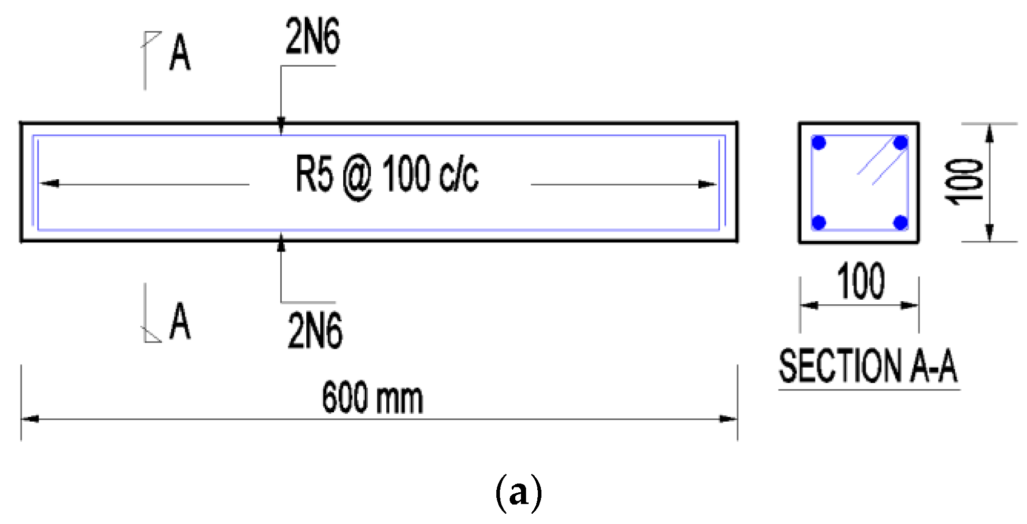
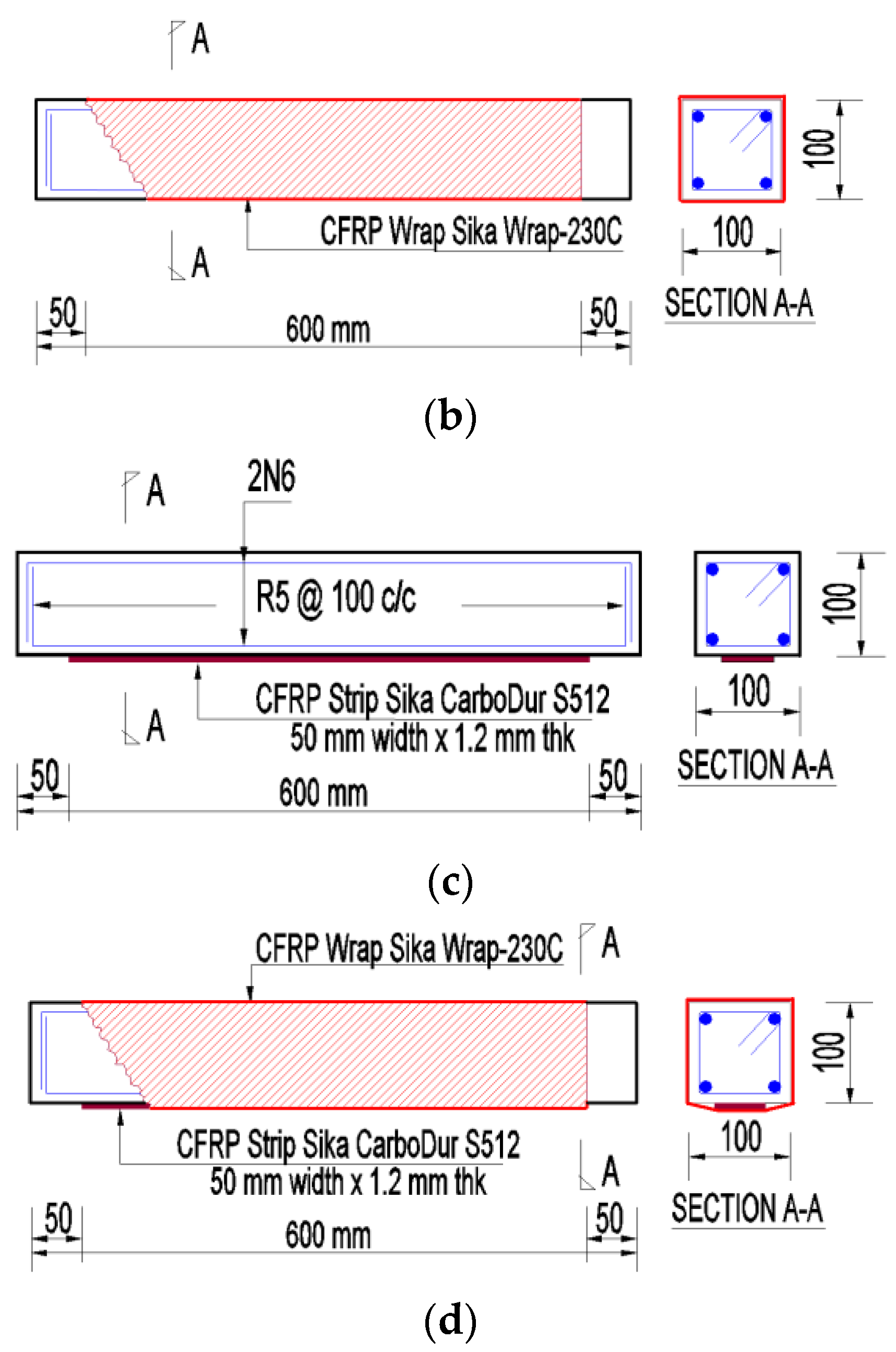
2.1. Preparation of RC Beam Samples and Reinforcement Details

Four groups of RC beams with dimensions of 600 × 100 × 100 mm were tested to evaluate the failure behaviour of the RC beams with and without CFRP strengthening under impact dynamic loads, as presented in Table 1.
All the beams were reinforced with two longitudinal bars 2N6 at the top and bottom, with shear links of R5 at 100 mm centre to centre, as presented in Figure 1. Three samples from each group were cast and tested; however, for the unstrengthened (B1) group, nine beams were cast, where three of them were tested under static conditions, and the rest were subjected to impact loads within different drop heights and denoted as (B1a and B1b) to determine the suitable drop height. The beams of group (B2) were wrapped with one layer of CFRP (Sika Wrap-230C, Sika, Baar, Switzerland) sheet to improve the shear strength of the beam and concrete confinement. On the other hand, the beams of group (B3) were strengthened with one layer of CFRP strip (Sika CarboDur S512, Sika, Baar, Switzerland) with a thickness of 1.2 mm, width of 50 mm, and length of 500 mm on the tension zone to increase flexural resistance of the beam. Lastly, the RC beams of group (B4) were strengthened with both CFRP wrap and strip. Bars class AS4671 N with a cross-sectional area of 28 mm2 and a nominal diameter of 6 mm were used as longitudinal reinforcement, while bars class R with a cross-sectional area of 19.6 mm2 and a diameter of 5 mm were utilized as a close stirrup.

2.2. Material Properties

The specimens were cast into two batches, where the beams of group (B1) were cast in the first batch, while the other groups were cast in the second batch with a target compressive strength of 35 MPa. Table 2 shows the results of cylindrical compressive strength and modulus of rupture for the tested samples. The CFRP (Sika CarboDur fabric) was used with a thickness of 0.13 mm to wrap the beam, and it was sticking on the beam concrete surface via epoxy type Sikadur-330, which consists of thixotropic epoxy-based impregnating resin and adhesive. The CFRP-type (Sika CarboDur S512) sheets were used as a longitudinal strip and stuck to the beam surface by using epoxy type Sikadur-30, which consists of epoxy resins with a special filler that might be used at temperature range of 8 °C to 35 °C. The details of the adopted materials are shown in Table 2.

2.3. Bonding Procedure of CFRP

Initially, the surface of all the beam samples was roughened via chisel and cutter to make it uneven and increase the adhesive strength between CFRP sheets and the beams. The dust particles were carefully cleaned and removed after the above procedure to avoid trapped dust in the epoxy layer.
After that, the epoxy layer was applied to the RC beams and strengthened with CFRP sheets. In the case of RC beam group (B2), a thin layer of epoxy-type Sikadur-330 with a thickness of about 2 mm was applied evenly across all the beam faces, and then the CFRP sheets were wrapped in the transverse direction of the beam. The main reason for beam wrapping was to evaluate its effects on the shear resistance of the RC beams and concrete confinement.
In the case of RC beam group (B3), the CFRP strips were stuck in the longitudinal direction of the beam to investigate its effects on the flexural resistance of the beam by using a thin layer of epoxy-type Sikadur-30 with a thickness of 2 mm. A small force was subjected to the CFRP strip to ensure that it was properly adhered to the beam surface. Finally, the RC beams of group (B4) were strengthened via both CFRP strips and wrap using the above procedures for groups B2 and B3.

2.4. Static Bending Test

The Baldwin Compression Machine was used during the static test, whereas the beam with a free span length of 500 mm was initially fixed on both sides of a metal frame of the compressive plates. The metal bar was placed on the beam centre-line to simulate a point load, as described in Figure 2. The top compressing metal plate of the Baldwin Compression Machine was pulled down to be in contact with the metal roller. A sensor linear variable differential transformer (LVDT) was utilized to measure the beam displacement at the mid-span. The test was performed via a gradual increment in the compressive force and stopped at the beam failure.

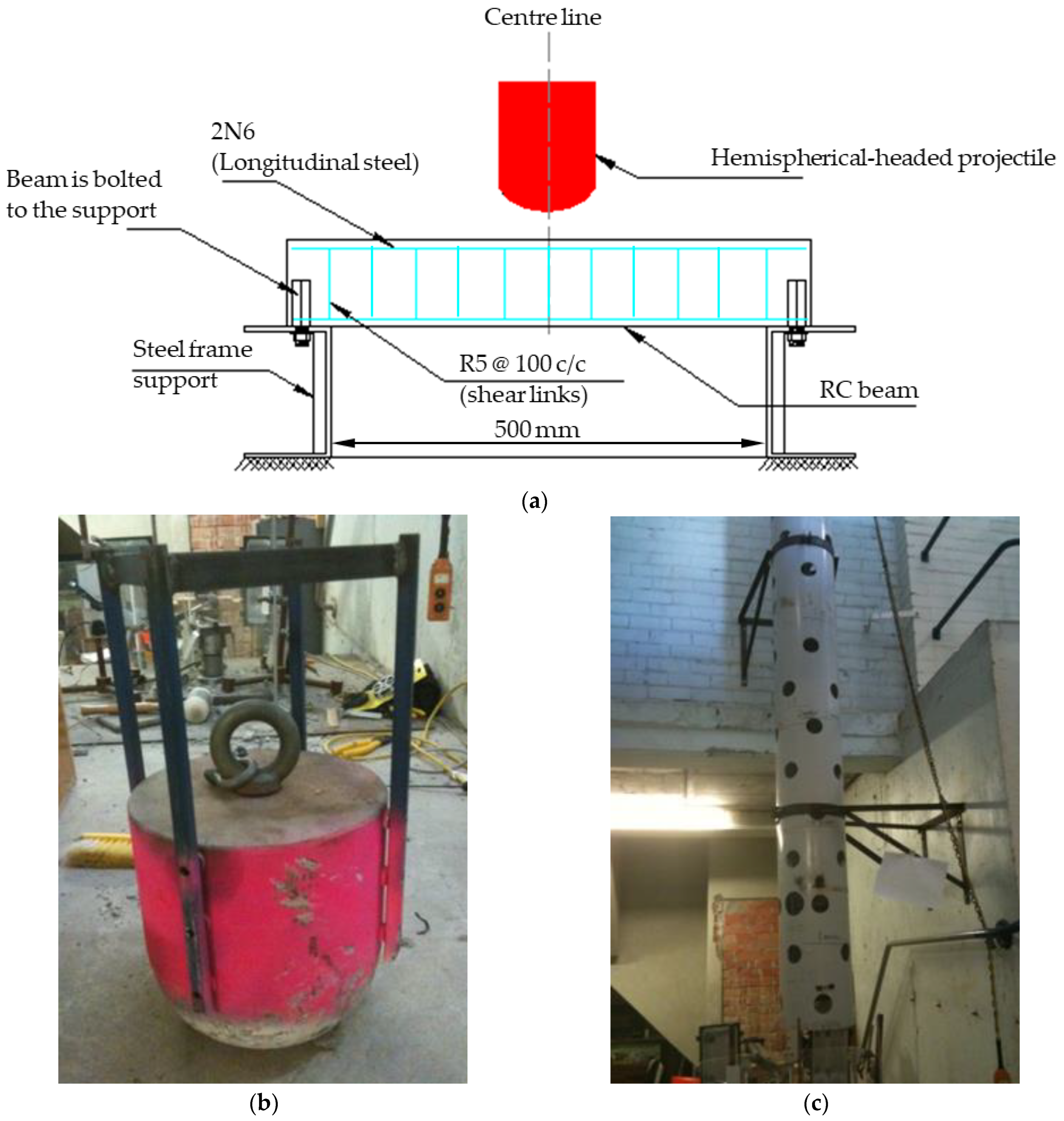
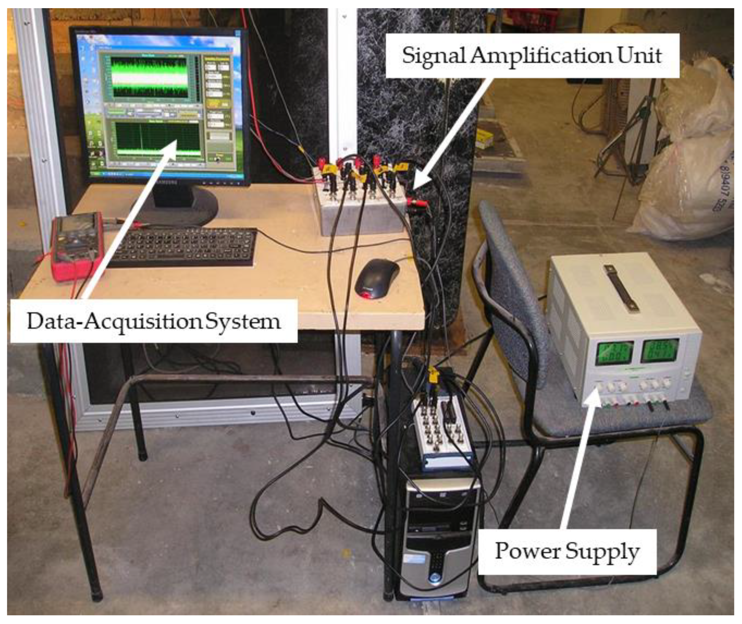
2.5. Drop Weight Test

The impact test was carried out by dropping a solid steel hemispherical-headed projectile weighing 92 kg on the concrete surface of the beam, as shown in Figure 3. The projectile dropped through a tunnel located above the tested sample. Similar to the static test, the sample with a free span of 500 mm was fixed to the steel frame on both sides to avoid the uplift of the sample during the impact. Furthermore, the pressures induced inside the guided tunnel during the impact were relieved and minimized by drilling holes around the tube tunnel section that could reduce the effects of these pressures on the drop speed of the projectile.
During the impact test, a high-speed data system with a maximum frequency of 2000 kHz and Ampere gain rate of 100–500 was used to record the laser LVDT measured displacement time history of the beam, as presented in Figure 4. The impact velocity during the test was measured by using a high-speed camera model MotionBLITZ® Cube 1.3 (SVS-Vistek, Gilching, Germany), up to 1000 frames per second with a recording time of 3.3 s at a full resolution of 640 × 512 pixels and a maximum speed at a reduced resolution reaching up to 32,000 frames per second.

3. Experimental Test Results

3.1. Results of Static Test

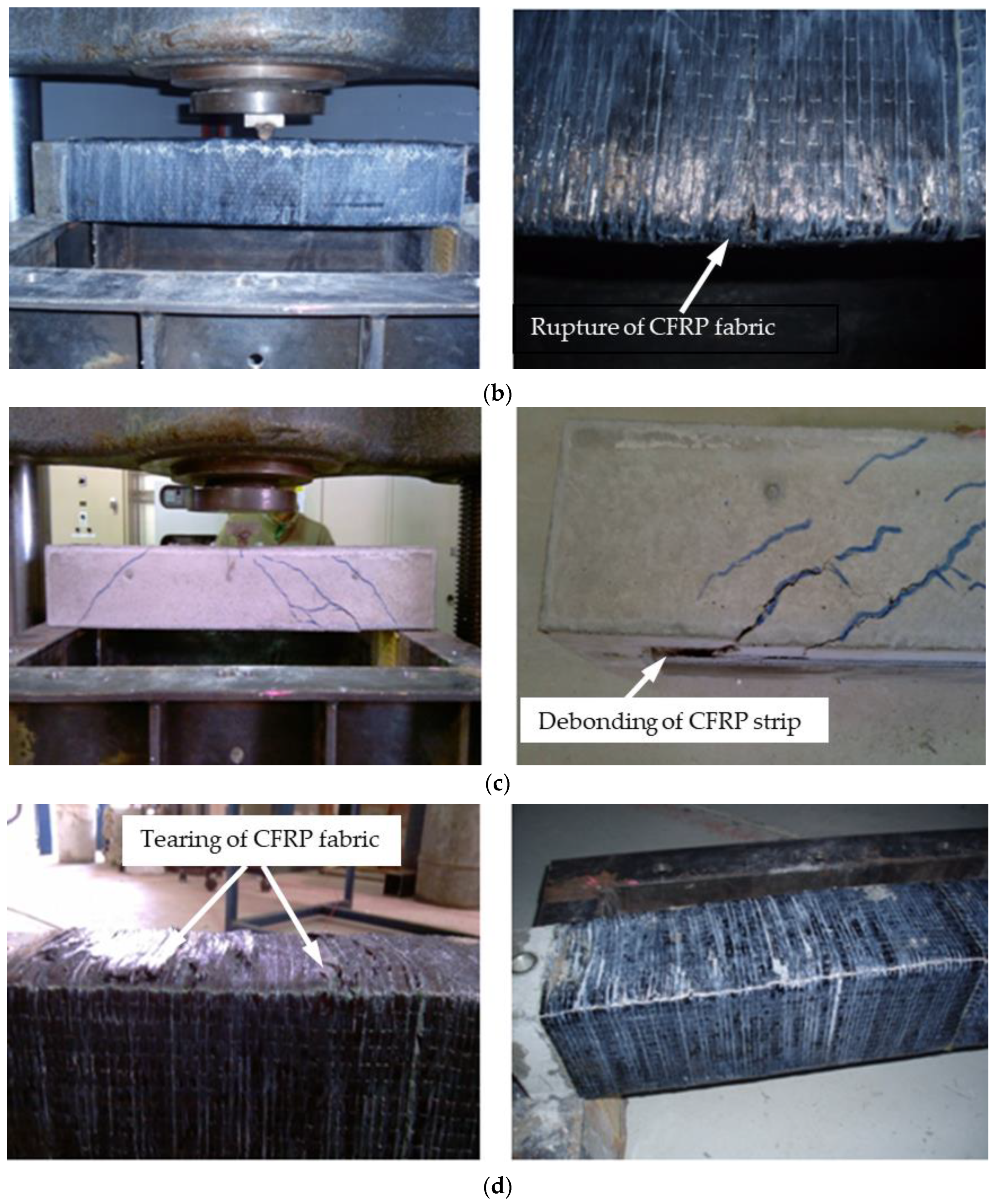
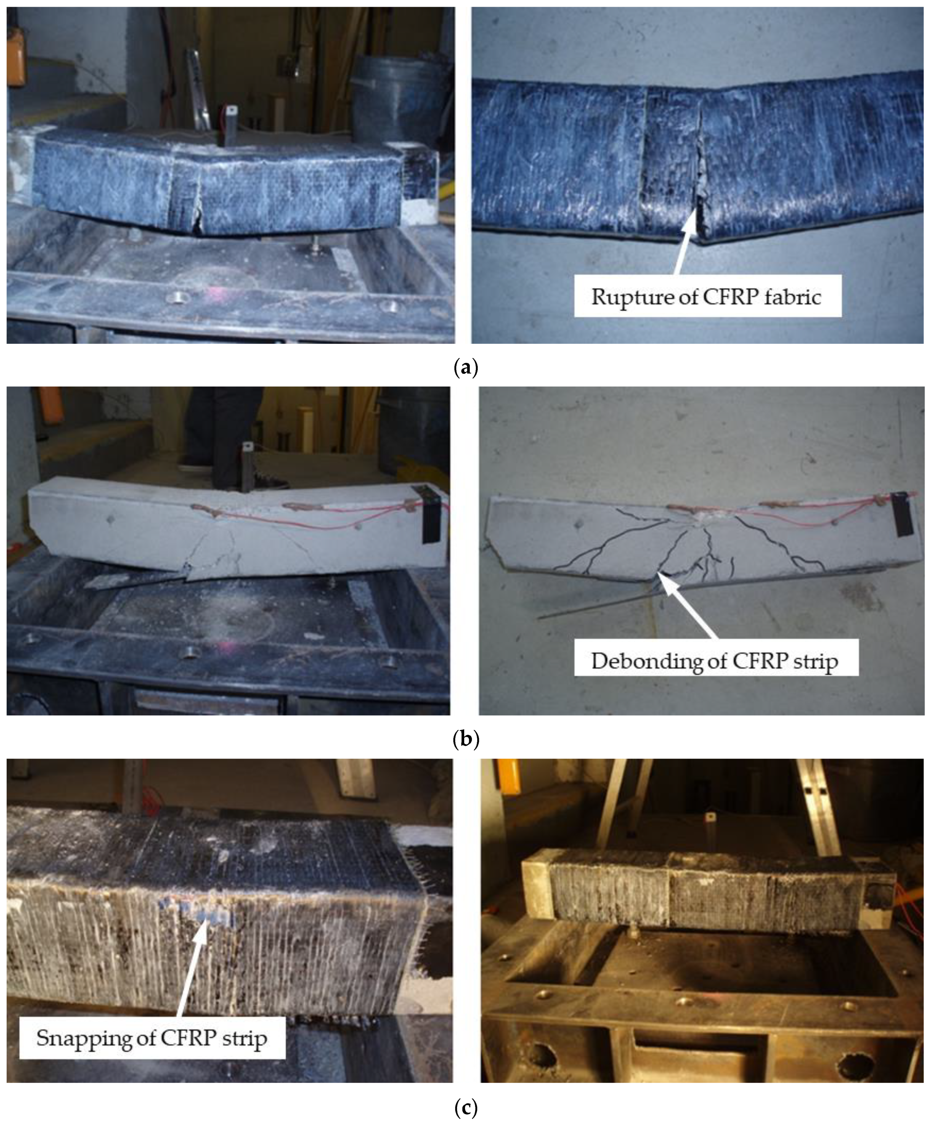
3.1.1. Failure Modes and Crack Pattern

The static test was performed by a Baldwin Compression Machine via gradual subjecting of the point load at the RC beam mid-span. A laser sensor (LVDT) recorded the maximum deflection at the mid-span during the test. In the case of unstrengthened RC beams group (B1), flexural cracks with a maximum width of 3 mm are observed at the beam mid-span, and these cracks gradually extend towards the supports, as shown in Figure 5a. The flexural cracks are also noted in the case of the RC beams of group (B2) at the beam mid-span with CFRP rupture, and these cracks spread upwards until beam failure with a maximum crack width of 3 mm at the middle of the beam, as observed in Figure 5b.
Figure 5c indicates that the CFRP strip of the RC beams of group (B3) deboned and caused beam failure. The deboning of CFRP sheets occurred at one side of the beam; therefore, the cracks initially observed at the locations of CFRP deboning and their propagation pattern are different than RC beams B1 and B2.
The cracks with a maximum depth of 2 mm are spread diagonally to the beam centre, and there was no obvious crack at the mid-span zone that reflected the role of the CFRP strip, which significantly developed the flexural resistance of the beam. In the case of the RC beams of group (B4), the flexural cracks were noted near the support at the locations of CFRP strip deboning signs. However, the CFRP wrap caused extra bonding and prevented premature debonding of the CFRP strip, as described in Figure 5d. Moreover, no cracks at the beam mid-span were observed, which again demonstrated the significant role of CFRP strengthening in enhancing the response of RC beams under impact loads.

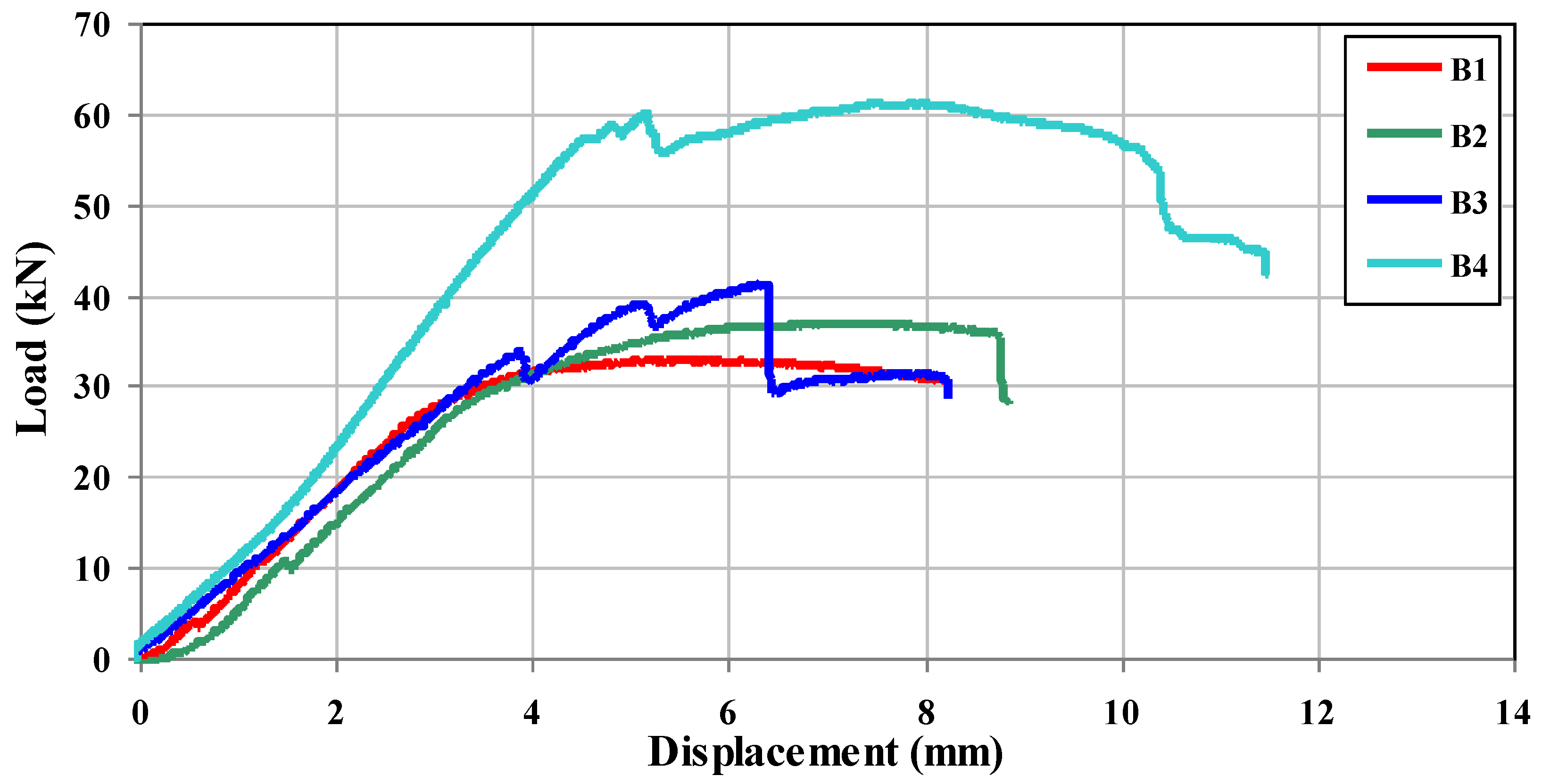
3.1.2. Load–Displacement Curves

The load–displacement curves of the tested beam samples were determined, as presented in Figure 6 and Table 3. The results revealed linear behaviour within the elastic zone until the yield point for all the tested beams. In the case of RC beam group (B1), the maximum average load recorded was approximately 33.07 kN, with an average mid-span deflection of 8 mm. On the other hand, the RC beams of group (B2) recorded a maximum average ultimate static load of 36.92 kN and an average deflection of 8.77 mm. The load–displacement curve of RC beam group (B2) showed a sharp section that might be attributed to the cracking of hardened epoxy. Generally, a slight improvement in the ultimate load capacity can be noted in the case of RC beam group (B2) compared to the unstrengthened beams (B1), which might attributed to the wrapping of the CFRP sheets on the beam surface.
The CFRP strengthened in the RC beam of the group (B3) increased the average ultimate load-carrying capacity of the beam by 24.80%, compared with the unstrengthened beams of the group (B1). A decrease in the load at a few locations can noted because the CFRP strips are de-bonding from the beam surface during the impact test. The beam recorded an average ultimate load of 41.27 kN with a maximum deflection of 8.24 mm, as shown in Table 3. The results proved a significant improvement in the flexural strength of the RC beam group (B4) by 84.88% compared with the RC beam of the group (B1), with a recorded maximum load of 61.14 kN and a deflection of 10.29 mm. The above results emphasized that the proper bonding of CFRP could considerably enhance the behaviour of RC beams under impact loads.

3.2. Results of the Impact Test

Figure 3 presents the drop weight testing system used to investigate the effect of using three different CFRP-strengthening schemes on the dynamic response of the RC beam under impact loads. The impact velocity during the test was determined via a high-speed camera model MotionBLITZ® Cube 1.3, while the sensor laser LVDT recorded the beam displacement at the mid-span. The RC beams of group (B1) were tested at different drop heights of 0.6 m and 1 m, respectively, to select the proper drop height that could cause significant beam damage. The results indicated minor damage with cracks at the mid-span with maximum and residual average displacements of 11.0 mm and 5.0 mm, respectively, for RC beam group (B1) at a drop height of 0.6 m, as described in Figure 7. A collapse in the RC beams of group (B1) was observed at a drop height of 1 m within an average crack width of 19 mm at the mid-span, which spread vertically upwards from the bottom of the beams. According to the above results, the drop height of 1 m was utilized in the subsequent tests to investigate the response of the RC beam with CFRP strengthening under impact loads.
Figure 8a indicates that the RC beams of group (B2) suffered significant damage at a drop height of 1 m, with an average crack width of 10 mm at the beam mid-span with CFRP rupturing along the fibre direction. Compared with the beams of group (B1), diagonal shear failure was not noted near the supports, which reflected the significant role of CFRP wrapping in enhancing the shear resistance of the RC beam under impact loads. In the case of RC beam group (B3), the CFRP strips were debonded at several locations, causing extensive flexural cracks at these locations only instead of the beam mid-span. Furthermore, shear failure occurred near the beam support. The above results proved that beam strengthening with CFRP strip is more effective than beam wrapping, especially in load capacity and deflection terms, which could significantly enhance the flexural beam strength.
The final impact test was performed on the RC beams of group (B4), as described in Figure 8c. The beams remained intact after the test, with only a slight residual deflection compared with other tests. A minor tearing in the CFRP wrap was observed at various locations, mainly near the supports, without CFRP rupture and flexural cracks or debonding. The results revealed the use of the CFRP strip and wrap efficiency to increase the strength of the beam under impact loading resistance.
Furthermore, the average deflection of the RC beams group (B4) showed a lower value than other beams tested at the same drop height and recorded at 8 mm, as shown in Table 4. Once again, these results indicated that using CFRP wrap combined with the strip is more effective in reducing the influences of impact loads than the other wrapping procedures tested above.

4. Finite Element Modelling

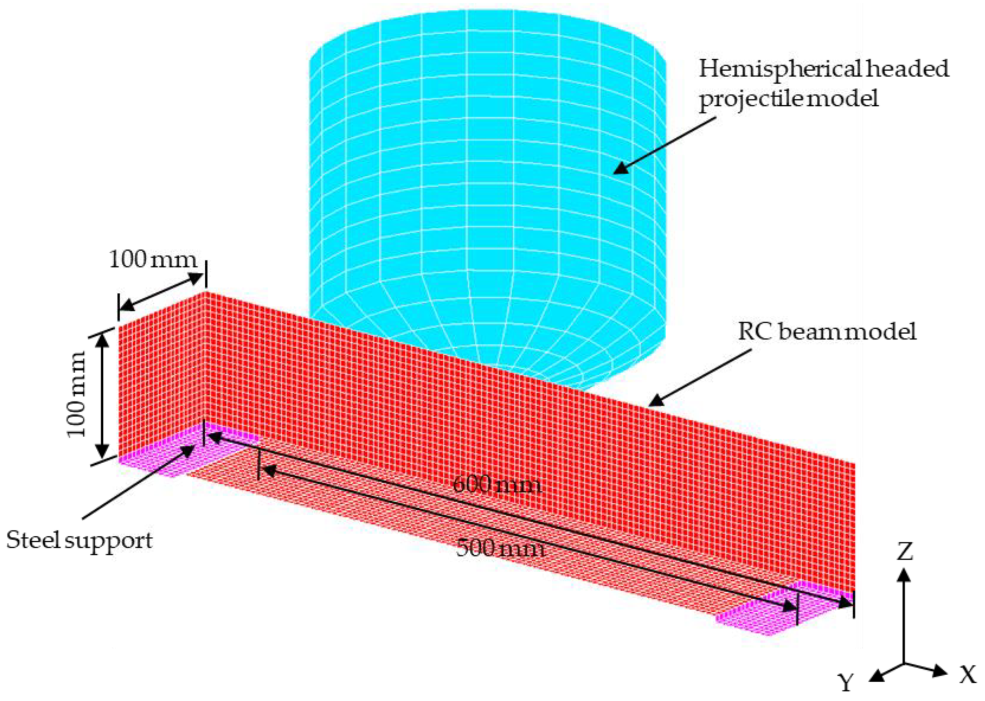
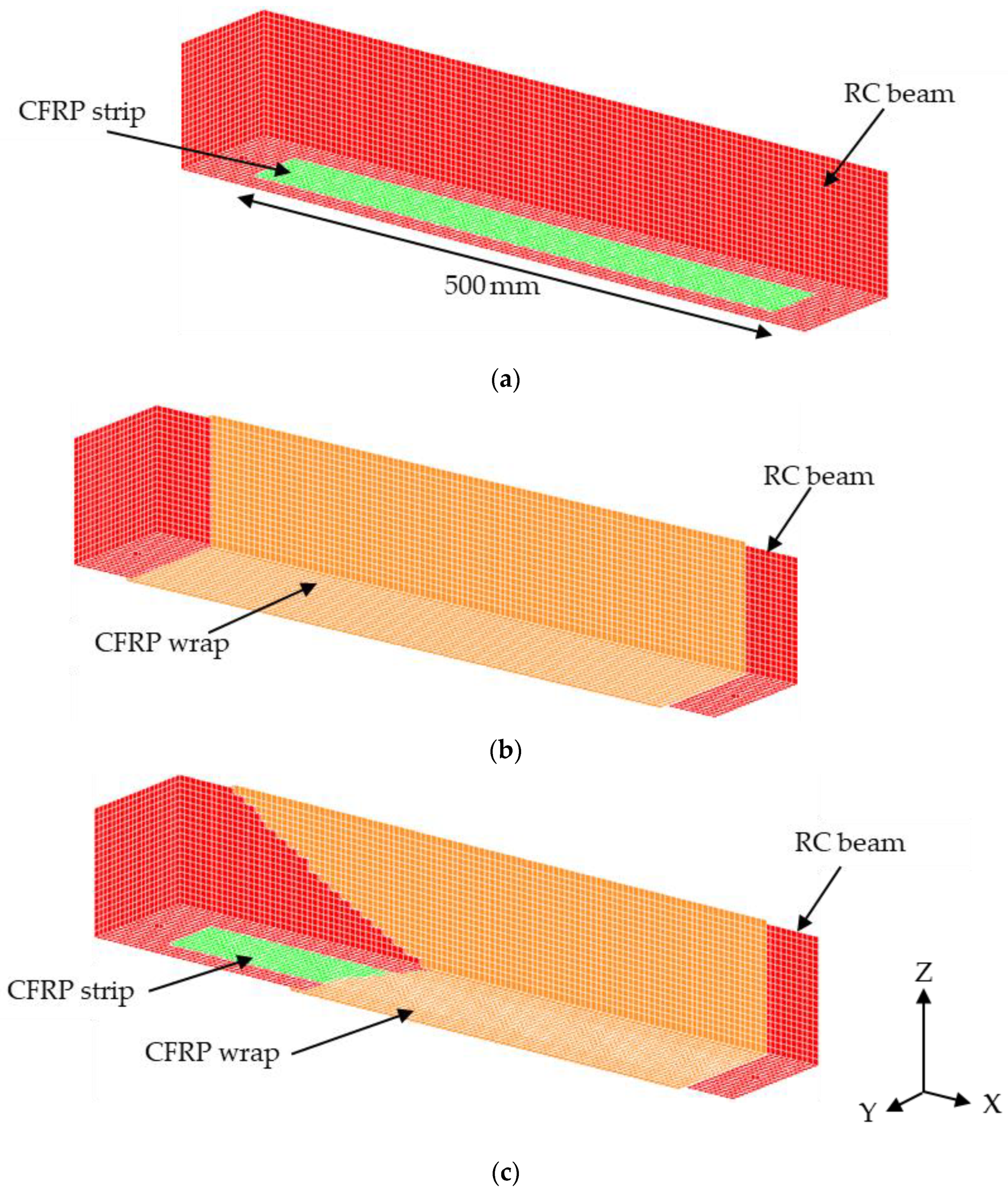
4.1. Geometry and Meshing

The finite element modelling was conducted by using LS-DYNA software to investigate the dynamic behaviour of RC beams under different loading conditions [33]. An eight-node element (SOLID 164) was adopted to simulate the concrete beam, hemispherical-headed projectile, and steel support, as shown in Figure 9. A default option (constant stress solid elements (ELFORM = 1)) was adopted, which utilized a reduced (one point) integration plus viscous hourglass control for faster element formulation.
The convergence test proved that a mesh size of 5 × 5 × 5 mm for RC beam and steel supports is efficient in terms of accuracy with less computational time and lower costs. The longitudinal steel reinforcements and shear links were simulated by using a two-node Hughes–Liu beam element with 2 × 2 Gauss quadrature integration. The CFRP strip of dimension 500 × 50 × 1.4 mm applied on the tension surface below the RC beam and the CFRP wrapping of the RC beam with and without the strip were simulated by using a Belytschko–Tsay 3D shell element [33], as shown in Figure 10.

4.2. Material Model

4.2.1. Concrete

The RC beams were modelled via Material Model 72Rel3 (MAT CONCRETE DAMAGE REL3) due to its capability to analyze the RC structure subjected to explosion loads with high accuracy and reliable outcomes [40,41]. The MAT_ADD_EROSION option was adopted to eliminate the elements that did not participate in the impact resistance of the beam during the analysis. The concrete mesh will disappear when the tensile stress reaches the values of the rupture modulus listed in Table 2 above. Careful usage of erosion is necessary to eliminate the concrete materials that resulted in a severe violation in the mass conservation of the structure [42].

4.2.2. Steel Reinforcement

The elastoplastic Material Model 24 (MAT PIECEWISE LINEAR PLASTICITY) is adopted to model the steel reinforcement, with properties shown in Table 2 above. This material model permits the user to input an effective stress versus an effective plastic strain curve and a curve defining the strain rate scaling effect on yield stress. Each point of effective plastic strain (EPS) corresponding to the yield stress (ES) is introduced based on the steel properties. Moreover, the effect of the strain rate on steel is considered by defining the (LCSR) option, which mainly depends on the values of the dynamic increase factor curve.

4.2.3. Hemispherical-Headed Projectile and Supports

The hemispherical-headed projectile and steel support are to be assumed rigid and simulated by using Material 20 (MAT_RIGID), available in the LS-DYNA library.

4.2.4. CFRP

Material model 54 (MAT ENHANCED COMPOSITE DAMAGE TITLE) was adopted to simulate the CFRP sheets [43,44]. The lamina failure criterion of this material was according to Chang–Chang failure, which includes four failure modes of CFRP fiber: the tensile mode, compressive mode, tensile matrix, and compressive matrix [33].

4.3. Boundary Condition and Contact

The nodes of bolt locations and steel support of the RC beam are fixed. The contact option “AUTOMATIC SURFACE-TO-SURFACE” available in the LS-Dyna library was used between the beam and the boundary elements to avoid the penetration of the distorted beam material into the steel support. The perfect bond between concrete and steel reinforcement might not give a reliable assessment of the RC beam behavior, particularly under impact loads [45]. Therefore, the CONTACT 1D option available in the LS-Dyna library was used to simulate the bond slip between the concrete and reinforcement bars with a default control option for static and dynamic friction coefficient. The bond between reinforcement bars and the concrete was assumed to have an elastic–plastic relationship with the maximum shear stress τmax. τmax was calculated by
τ m a x = G S u m a x e h d m g D
where G S is the modulus of bond shear, u m a x is the maximum elastic slip, h d m g is the damage curve exponent, and D is the damage parameter, which is introduced as the sum of the absolute values of the plastic displacement increments. Shi et al. [45] performed several parametric tests and stated that the values of the effect of h d m g and D values are insignificant and might be ignored. In this study, G S is taken as 20 MPa/mm, and u m a x is 1.0 mm according to the recommendation proposed by Shi et al. [45].
The adhesive contact between the concrete beam surface and the CFRP sheets was simulated by using an option “AUTOMATIC SURFACE TO SURFACE TIEBREAK” to simulate the expected delamination of the CFRP composite as well as the contact between the CFRP strip and wrap sheets. This contact option relies on the variables of the tensile and shear failure stresses (NFLS and SFLS) of epoxy. The NFLS and SFLS magnitudes were according to the bond strength of epoxy type “Sikadur-30” between concrete and CFRP strip sheets and the epoxy type “Sikadur-330” between concrete and CFRP wrap. Contact failure occurs if
σ n N F L S 2 + σ S S F L S 2 1
where σ n and σ S are the tensile and shear stresses at the interface, respectively. Various factors affect the defining of bond strength, which ranges between 4 MPa and 30 according to the applying quality of epoxy and CFRP sheets, curing days, and the temperature used during the curing after applying the CFRP sheets [39]. Simulation of the RC beam group (B3) was performed initially to determine these magnitudes due to the debonding of CFRP observed obviously during this test. The simulation did not stop until the debonding of CFRP sheets occurred. The NFLS and SFLS values were assumed to be 20 MPa for both parameters during the analysis of the RC beam group (B3); thus, those values were adopted in all the subsequent models of RC beams strengthened by CFRP sheets. The initial velocity of the hemispherical head projectile nodes was according to the initial velocity determined during the experimental impact tests, as shown in Table 5. As expected, the impact velocities during the experimental tests were slightly slower than the theoretical velocities due to the air resistance.

4.4. Dynamic Increase Factor (DIF)

The strain rate effects of steel and concrete are included by obtaining the DIF curves via the empirical equations suggested by prior studies [36,37]. On the other hand, several studies stated that the strain rate effects of CFRP are insignificant compared with concrete and steel materials [46,47]; therefore, its effects are ignored in the current study.

5. Comparison between Numerical and Experimental Results
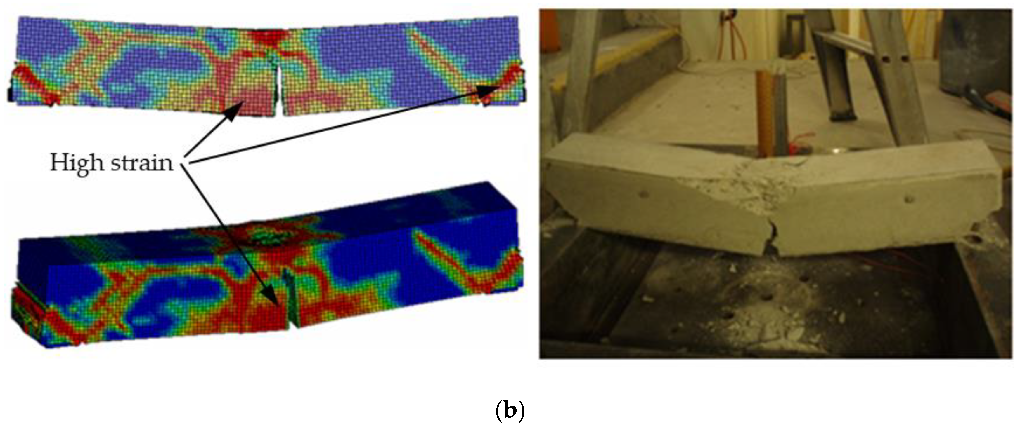
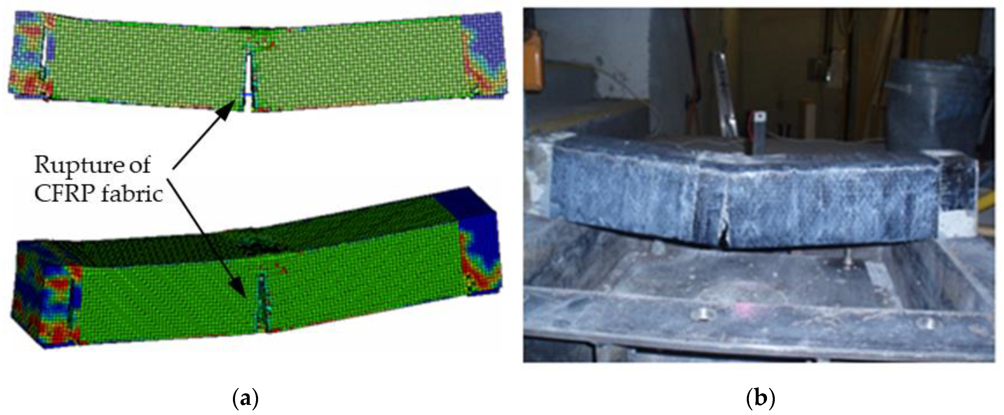
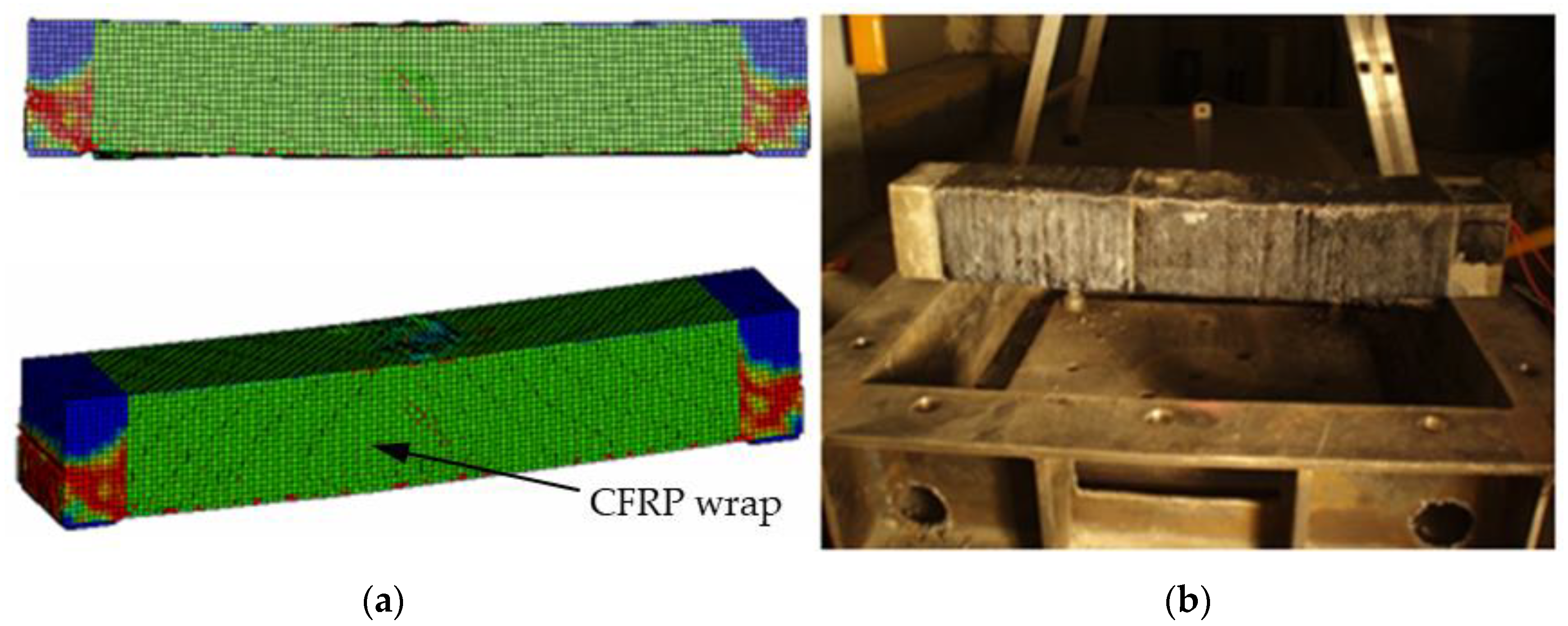
5.1. Failure Modes

A similar failure model was obtained for the simulated unstrengthened RC beams of group (B1) with the experimental failure mode within an impact load of 0.6 m and 1 m drop height, as shown in Figure 11. High strain values were observed around the beam mid-span where the headed projectile impacted the beam and at the boundary on which the beam was fixed to the steel frame support. The calculated plastic strain distribution agreed well with the cracks noted during the experimental test.
Figure 12 reveals that the CFRP of the RC beams of the group (B2) model at the mid-span is ruptured, similar to the experimental test at a drop height of 1 m, which might attributed to the location of the normal CFRP in the fibre direction, which is considered relatively weak.
Similar to the experimental results of the RC beams of group (B3), the debonding of the CFRP strip was captured at a drop height of 1.0 m during the numerical analysis, as shown in Figure 13. Debonding of the CFRP strip occurs after the prescribed failure criterion of the contact option between the RC beam and CFRP sheets is reached. Moreover, a high stress concentration and diagonal shear failure at the boundaries on both sides of the beam are noted during the numerical simulation.
Finally, the numerical results for the RC beams group (B4) revealed minor damage with a slight residual deflection compared to the experimental test, as shown in Figure 14. The above results reflected the efficiency of using the numerical simulation to closely resemble the test observations of RC beam strengthened by CFRP under impact load with high accuracy and less computational time and costs.

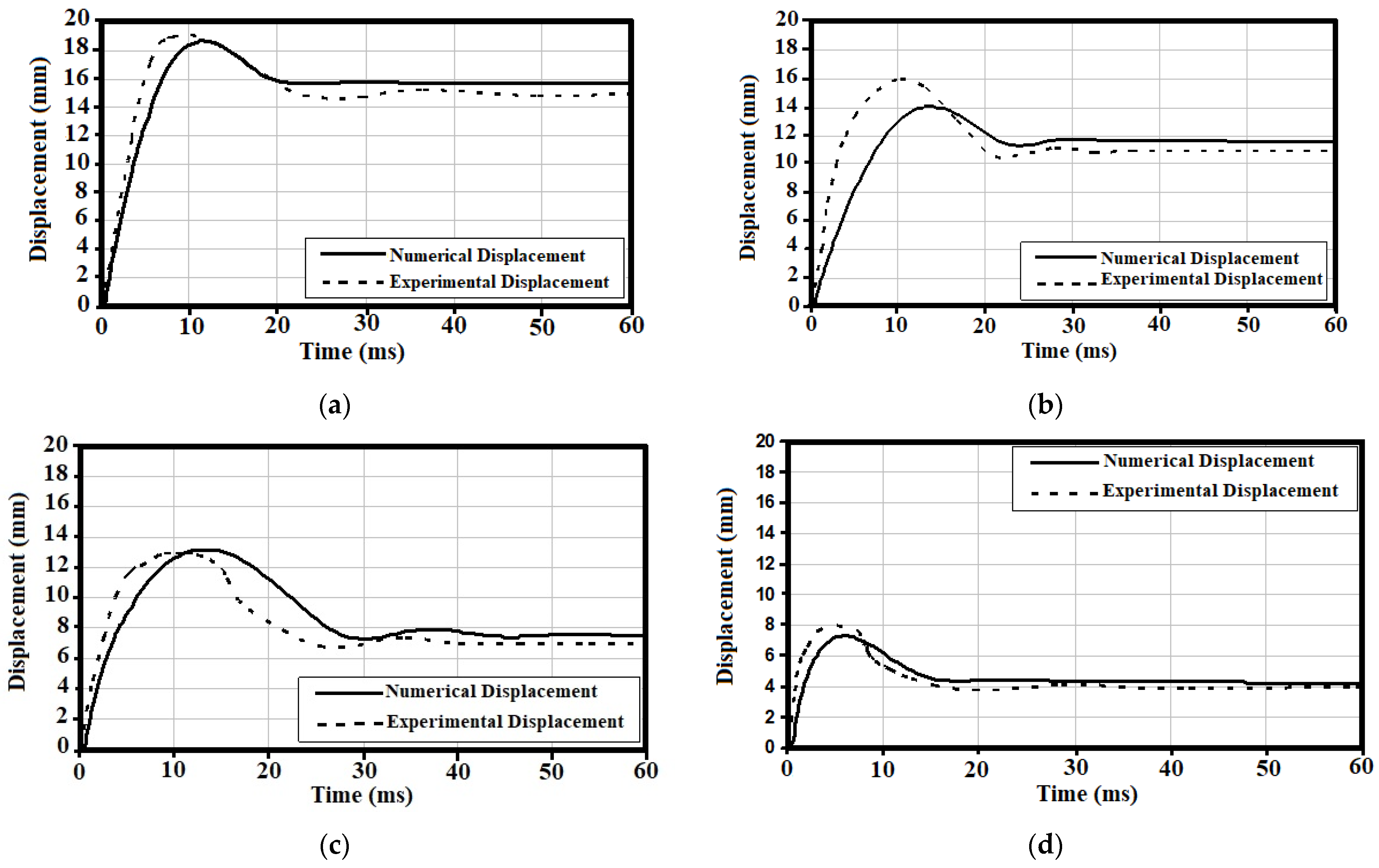
5.2. Load–Displacement Response

The average displacement–time response of the RC beams tested groups under a drop height of 1 m was determined to ensure the accuracy of the proposed numerical models, as shown in Figure 15.
The results proved a good agreement between numerical and experimental tests for the dynamic response behaviour within differences in maximum displacement at the mid-height of −12.5%, as shown in Table 6. These outcomes highlighted the reliability of the suggested numerical models in determining the response of RC beams under impact loads with less computation costs and time.

6. Conclusions

The results of this study can be summarized as follows:
  • The static test results proved that the beams of group (B4) strengthened via both a CFRP strip and wrap could significantly delay the debonding failure, within no cracks at the mid-span of the beam.
  • The results indicated that the average flexural strength of the RC beams of group (B4) strengthened with the CFRP strip and wrap increased by 84.88% compared with unstrengthened beam group (B1), with a recorded maximum load of 61.14 kN and a deflection of 10.29 mm.
  • The impact test results recorded a collapse in the unstrengthened beams of group (B1) during a drop weight test from a height of 1 m within an average maximum crack width at the mid-span of 19 mm, which spread vertically upwards from the bottom of the beam. At the same tested height, minor damage for RC beam group (B4) with an average maximum deflection of 8 mm was determined.
  • The numerical analysis results proved a good agreement with the experimental tests in terms of failure modes and the load–displacement response. The maximum differences of −12.5% reflect the capability of using these models to perform further parametric studies to obtain optimal CFRP strengthening for RC beams under impact loads for future investigations.
In conclusion, the above results proved the efficiency of using CFRP strengthening to increase the resistance capacities of RC beams under static and impact loads.

Author Contributions

Conceptualization, A.A.M.; Data curation, A.A.M.; Formal analysis, M.H.M.; Funding acquisition, H.H.; Investigation, M.H.M.; Methodology, M.H.M.; Project administration, H.H.; Resources, A.A.M. and H.H.; Supervision, A.A.M. and H.H.; Validation, M.H.M. and A.A.M.; Visualization, A.A.M.; Writing—original draft, M.H.M. and A.A.M.; Writing—review and editing, M.H.M. All authors have read and agreed to the published version of the manuscript.

Funding

The authors would like to thank Universiti Kebangsaan Malaysia (UKM) for providing financial support through projects DIP-2021-014 and FRGS/1/2021/TK0/UKM/02/26.

Data Availability Statement

The data presented in this study are available on request from the corresponding author.

Conflicts of Interest

The authors declare that they have no conflicts of interest.

References

  1. Zhang, C.; Gholipour, G.; Mousavi, A.A. State-of-the-art review on responses of RC structures subjected to lateral impact loads. Arch. Comput. Methods Eng. 2021, 28, 2477–2507. [Google Scholar] [CrossRef]
  2. Arsava, K.S.; Nam, Y.; Kim, Y. Nonlinear system identification of smart reinforced concrete structures under impact loads. J. Vib. Control 2016, 22, 3576–3600. [Google Scholar] [CrossRef]
  3. Liu, Y.; Dong, A.; Zhao, S.; Zeng, Y.; Wang, Z. The effect of CFRP-shear strengthening on existing circular RC columns under impact loads. Constr. Build. Mater. 2021, 302, 124185. [Google Scholar] [CrossRef]
  4. Mutalib, A.A.; Mussa, M.H.; Hao, H. Effect of CFRP strengthening properties with anchoring systems on PI diagrams of RC panels under blast loads. Constr. Build. Mater. 2019, 200, 648–663. [Google Scholar] [CrossRef]
  5. Kishi, N.; Mikami, H.; Matsuoka, K.; Ando, T. Impact behavior of shear-failure-type RC beams without shear rebar. Int. J. Impact Eng. 2002, 27, 955–968. [Google Scholar] [CrossRef]
  6. Saatci, S.; Vecchio, F.J. Nonlinear finite element modeling of reinforced concrete structures under impact loads. ACI Struct. J. 2009, 106, 717–725. [Google Scholar]
  7. Saatci, S.; Vecchio, F.J. Effects of shear mechanisms on impact behavior of reinforced concrete beams. ACI Struct. J. 2009, 106, 78–86. [Google Scholar]
  8. Cotsovos, D.M.; Stathopoulus, N.D.; Zeris, C.A. Behaviour of RC beams subjected to high rates of concentrated loading. J. Struct. Eng. 2008, 134, 1839–1851. [Google Scholar] [CrossRef]
  9. Bhatti, A.Q.; Kishi, N.; Mikami, H.; Ando, T. Elasto-plastic impact response analysis of shear-failure type RC beams with shear rebars. Mater. Des. 2009, 30, 502–510. [Google Scholar] [CrossRef]
  10. Cotsovos, D.M. A simplified approach for acessing the load-carrying capacity of reinforced concrete beams under concentrated load applied at high rates. Int. J. Impact Eng. 2010, 37, 907–917. [Google Scholar] [CrossRef]
  11. Ngo, T.; Mendis, P.; Gupta, A.; Ramsay, J. Blast loading and blast effects on structures—An overview. Electron. J. Struct. Eng. 2007, 7, 76–91. [Google Scholar] [CrossRef]
  12. Li, Q.M.; Reid, S.R.; Wen, H.M.; Telford, A.R. Local impact effects of hard missiles on concrete targets. Int. J. Impact Eng. 2005, 32, 224–284. [Google Scholar] [CrossRef]
  13. Bangash, M.Y.H. Impact and Explosion: Structural Analysis and Design; CRC Press: Boca Raton, FL, USA, 1993. [Google Scholar]
  14. Zhao, W.; Qian, J.; Jia, P. Peak response prediction for RC beams under impact loading. Shock Vib. 2019, 2019, 6813693. [Google Scholar] [CrossRef]
  15. Gholipour, G.; Zhang, C.; Mousavi, A.A. Loading rate effects on the responses of simply supported RC beams subjected to the combination of impact and blast loads. Eng. Struct. 2019, 201, 109837. [Google Scholar] [CrossRef]
  16. Zhao, D.-B.; Yi, W.-J.; Kunnath, S.K. Shear mechanisms in reinforced concrete beams under impact loading. J. Struct. Eng. 2017, 143, 04017089. [Google Scholar] [CrossRef]
  17. Yi, W.-J.; Zhao, D.-B.; Kunnath, S.K. Simplified Approach for Assessing Shear Resistance of Reinforced Concrete Beams under Impact Loads. ACI Struct. J. 2016, 113, 747–756. [Google Scholar] [CrossRef]
  18. Fu, Y.; Yu, X.; Dong, X.; Zhou, F.; Ning, J.; Li, P.; Zheng, Y. Investigating the failure behaviors of RC beams without stirrups under impact loading. Int. J. Impact Eng. 2020, 137, 103432. [Google Scholar] [CrossRef]
  19. Teng, J.G.; Chen, J.F.; Smith, S.T.; Lam, L. Behavior and strength of FRP-strengthened RC structures: A State-of-the-art review. Proc. Inst. Civ. Eng. Struct. Build. 2003, 156, 51–62. [Google Scholar] [CrossRef]
  20. Wu, Y.-F.; Huang, Y. Hybrid bonding of FRP to reinforced concrete structures. J. Compos. Constr. 2008, 12, 266–273. [Google Scholar] [CrossRef]
  21. Cantwell, W.J.; Smith, K. The static and dynamic response of CFRP-strengthened concrete structures. J. Mater. Sci. Lett. 1999, 18, 309–310. [Google Scholar] [CrossRef]
  22. Tang, T.; Saadatmanesh, H. Behavior of concrete beams strengthened with fiber-reinforced polymer laminates under impact loading. J. Compos. Constr. 2003, 7, 209–218. [Google Scholar] [CrossRef]
  23. Jerome, D.; Ross, C. Simulation of the dynamic response of concrete beams externally reinforced with carbon-fiber reinforced plastic. Comput. Struct. 1997, 64, 1129–1153. [Google Scholar] [CrossRef]
  24. Zhao, H.; Kong, X.; Fu, Y.; Gu, Y.; Wang, X. Numerical investigation on dynamic response of RC T-beams strengthened with CFRP under impact loading. Crystals 2020, 10, 890. [Google Scholar] [CrossRef]
  25. Tang, T.; Saadatmanesh, H. Analytical and experimental studies of fiber-reinforced polymer-strengthened concrete beams under impact loading. ACI Struct. J. 2005, 102, 139. [Google Scholar]
  26. White, T.W.; Soudki, K.A.; Erki, M.-A. Response of RC beams strengthened with CFRP laminates and subjected to a high rate of loading. J. Compos. Constr. 2001, 5, 153–162. [Google Scholar] [CrossRef]
  27. Pham, T.M.; Hao, H. Behavior of fiber-reinforced polymer-strengthened reinforced concrete beams under static and impact loads. Int. J. Prot. Struct. 2017, 8, 3–24. [Google Scholar] [CrossRef]
  28. Pham, T.M.; Hao, H. Impact behavior of FRP-strengthened RC beams without stirrups. J. Compos. Constr. 2016, 20, 04016011. [Google Scholar] [CrossRef]
  29. Soleimani, S.M.; Banthia, N.; Mindess, S. Sprayed GFRP shear-strengthened reinforced concrete Beams under Impact Loading. In Advances in Construction Materials 2007; Springer: Berlin/Heidelberg, Germany, 2007; pp. 279–286. [Google Scholar]
  30. Soudki, K.; Alkhrdaji, T. Guide for the Design and Construction of Externally Bonded FRP Systems for Strengthening Concrete Structures: ACI 440.2 R-08; American Concrete Institute: Farmington, MI, USA, 2008. [Google Scholar]
  31. Fujikake, K.; Li, B.; Soeun, S. Impact response of reinforced concrete beam and its analytical evaluation. J. Struct. Eng. 2009, 135, 938. [Google Scholar] [CrossRef]
  32. Hamed, E.; Rabinovitch, O. Dynamic behavior of reinforced concrete beams strengthened with composite materials. J. Compos. Constr. 2005, 9, 429–440. [Google Scholar] [CrossRef]
  33. LS-DYNA. Keyword User’s Manual V971; LSTC: Livermore, CA, USA, 2006. [Google Scholar]
  34. Asprone, D.; Cadoni, E.; Prota, A. Experimental analysis on tensile dynamic behavior of existing concrete under high strain rates. Struct. J. 2009, 106, 106–113. [Google Scholar]
  35. Comité Euro-International du Béton. CEB-FIP Model Code 1990; Thomas Telford Ltd.: London, UK, 1993. [Google Scholar]
  36. Malvar, L.J. Review of static and dynamic properties of steel reinforcing bars. Am. Concr. Inst. Mater. J. 1998, 95, 609–616. [Google Scholar]
  37. Malvar, L.J.; Ross, C.A. Review of strain rate effects for concrete in tension. Am. Concr. Inst. Mater. J. 1998, 95, 735–739. [Google Scholar]
  38. Yang, G.; Lok, T.-S. Analysis of RC Structures Subjected to Air-blast Loading Accounting for Strain Rate Effect for Steel Reinforcement. Int. J. Impact Eng. 2007, 34, 1924–1935. [Google Scholar] [CrossRef]
  39. Sika-Australia-Pty-Ltd. Structural Strengthening. Available online: https://aus.sika.com/en/construction/structural-strengthening.html (accessed on 1 January 2020).
  40. Malvar, L.J.; Crawford, J.E.; Wesevich, J.W.; Simons, D. A plasticity concrete material model for DYNA3D. J. Impact Eng. 1997, 19, 847–873. [Google Scholar] [CrossRef]
  41. Yonten, K.; Manzari, M.T.; Eskandarian, A.; Marzougui, D. An evaluation of constitutive models of concrete in LS-DYNA finite element code. In Proceeding of the 15th ASCE Engineering Mechanics Conference, New York, NY, USA, 2–5 June 2002. [Google Scholar]
  42. Tang, E.K.; Hao, H. Numerical simulation of a cable-stayed bridge response to blast loads, Part I: Model development and response calculations. Eng. Struct. 2010, 32, 3180–3192. [Google Scholar] [CrossRef]
  43. Han, H.; Taheri, F.; Pegg, N.; Lu, Y. A numerical study on the axial crushing response of hybbrid and ± braided tubes. Compos. Struct. 2007, 80, 253–264. [Google Scholar] [CrossRef]
  44. Mamalis, A.; Manolakos, D.; Ioannidis, M.; Kostazos, P. Crushing of hybrid square sandwich composite vehicle hollow bodyshells with reinforced core subjected to axial loading. Compos. Struct. 2003, 61, 175–186. [Google Scholar] [CrossRef]
  45. Shi, Y.; Li, Z.-X.; Hao, H. Bond slip modelling and its effects on numerical analysis of blast-induced responses of RC columns. Struct. Eng. Mech. 2009, 32, 251–267. [Google Scholar] [CrossRef]
  46. Welsh, L.M.; Harding, J. Dynamic tensile response of unidirectionally-reinforced carbon epoxy and glass epoxy composites. In Proceedings of the 5th International Conference on Composite Materials, San Diego, CA, USA, 29 July 1985. [Google Scholar]
  47. Kimura, H.; Itabashi, M.; Kawata, K. Mechanical characterization of unidirectional CFRP thin strip and CFRP cables under quasi-static and dynamic tension. Adv. Compos. Mater. 2001, 10, 177–187. [Google Scholar] [CrossRef]
Figure 1. Reinforcement and wrapping details of tested RC beams: (a) B1, (b) B2, (c) B3, (d) B4.
Fibers 12 00063 g001aFibers 12 00063 g001b
Figure 2. Static load test setup.
Fibers 12 00063 g002
Figure 3. Setup of impact test: (a) RC beam fixed to the steel frame support, (b) hemispherical headed projectile, and (c) guided cylindrical tube.
Fibers 12 00063 g003
Figure 4. Data-acquisition system.
Fibers 12 00063 g004
Figure 5. Static test results of RC beams: (a) B1, (b) B2, (c) B3, (d) B4.
Fibers 12 00063 g005aFibers 12 00063 g005b
Figure 6. The load–displacement curve at the static test for RC beams of groups B1, B2, B3, and B4.
Fibers 12 00063 g006
Figure 7. Drop test of RC beam (B1) at heights of (a) 0.6 m, (b) 1 m.
Fibers 12 00063 g007
Figure 8. Failure modes and cracks pattern during a 1 m drop weight impact test of RC beams of (a) B2, (b) B3, (c) B4.
Fibers 12 00063 g008
Figure 9. Finite element modelling of the impact test setup.
Fibers 12 00063 g009
Figure 10. Modelling of RC beams with (a) CFRP strip, (b) CFRP wrap, and (c) CFRP strip and wrap.
Fibers 12 00063 g010
Figure 11. Comparison between failure modes of the RC beams group (B1) at a drop height of (a) 0.6 m, (b) 1 m.
Fibers 12 00063 g011aFibers 12 00063 g011b
Figure 12. Comparison between failure modes of the RC beams group (B2) at a drop height of 1 m: (a) numerical analysis, (b) experimental test.
Fibers 12 00063 g012
Figure 13. Comparison between failure modes of the RC beams group (B3) at a drop height of 1 m: (a) numerical analysis, (b) experimental test.
Fibers 12 00063 g013
Figure 14. Comparison between failure modes of RC beam group (B4) at a drop height of 1 m: (a) numerical analysis, (b) experimental test.
Fibers 12 00063 g014
Figure 15. Comparison of displacement time history between numerical and experimental results at a drop height of 1 m for RC beam groups: (a) B1, (b) B2, (c) B3, and (d) B4.
Fibers 12 00063 g015
Table 1. Description of RC beam-strengthening schemes.
Group CodeDescription
B1Control: No strengthening
B2RC beam strengthened with one layer of CFRP (Sika Wrap-230C, Sika, Baar, Switzerland) wrap of 0.13 mm thickness
B3RC beam strengthened with one layer of 50 mm width and 500 mm long CFRP (Sika CarboDur S512, Sika, Baar, Switzerland) strip of 1.2 mm thickness provided by SIKA Australia PTY LTD, Wetherill Park, Australia, to the tension side of the beam
B4RC beam strengthened with the CFRP strip and then wrapped as described above
Table 2. Material properties of concrete, steel, CFRP, and epoxy.
Concrete Average   Compressive   Strength   f c (MPa) Modulus   of   Rupture   F R P (MPa)
B1, B1a, B1b37.785.97
B2, B3, B435.425.59
SteelYield stress f y (MPa)Young’s modulus E s (GPa)
Longitudinal steel506200
Shear stirrup305200
CFRP [39]Tensile strength f t (MPa)Young’s modulus E f (GPa)
Sika CarboDur S5122800165
Sika Wrap-230C3500230
Epoxy [39]Tensile strength f t (MPa)Young’s modulus E e (GPa)
Sikadur-303111.2
Sikadur-330304.5
Table 3. Comparison of the static test results between RC beams groups B1, B2, B2, and B4.
SpecimensMaximum Load (kN)Deflection (mm)Flexural Strength (MPa)Improvement in Strength (%)
B133.078.0029.76N/A
B236.928.7733.2211.64
B341.278.2437.1524.80
B461.1410.2955.0384.88
Table 4. Average deflection of tested RC beam groups under impact loads.
Tested BeamDrop Height (m)Average Deflection (mm)Average Residual Deflection (mm)Maximum Deflection Reduction (%)Residual Deflection (%)
B10.674.5--
11915--
B211611−15.79−26.67
B31137−31.58−53.33
B4184−57.89−73.33
Table 5. Impact velocity results during the experimental tests.
Tested GroupDrop Height (m)Experimental Impact Velocity (ms−1)Theoretical Impact Velocity (ms−1)
B1a0.63.323.43
B1b14.294.43
B214.304.43
B314.284.43
B414.344.43
Table 6. Differences of maximum displacement between numerical and experimental results at a drop height of 1 m.
Beam CodeMaximum Displacement (mm)Differences (%)
NumericalExperimental
B118.719−1.6
B21416−12.5
B313.2131.54
B47.38−8.76
Disclaimer/Publisher’s Note: The statements, opinions and data contained in all publications are solely those of the individual author(s) and contributor(s) and not of MDPI and/or the editor(s). MDPI and/or the editor(s) disclaim responsibility for any injury to people or property resulting from any ideas, methods, instructions or products referred to in the content.

