Abstract
In this study, we took a closer look at the thermal recyclability of CFRP composites used in the manufacture of high-pressure cylinders. Thermal analysis was used to determine the minimum temperature at which stable resin decomposition begins. The aim was to find temperature parameters and retention times with which the pyrolysis process is as economically viable as possible, and the recovered fibers retain optimum mechanical properties. The surface morphology of fibers annealed in both inert and oxidizing atmospheres was examined. In addition, the mechanical strengths under static as well as dynamic conditions of the newly manufactured laminates containing the recovered fibers were investigated. During research, it was found that reusing fibers is very difficult. The recycled carbon fibers were successfully compressed in an epoxy matrix in the form of a pre-impregnated carbon mat with the presence of air. The presence of oxygen during the thermal degradation of the composite severely damaged the surface and structure of the carbon fiber, causing composites made from these fibers to be mechanically weaker by more than 247%.
1. Introduction
Composites containing, inter alia, glass or carbon fiber-reinforced duroplastics, are materials that offer exceptional strength, stiffness, and lightness. Due to their properties, they are widely used in the automotive industry and aerospace, as well as railways, wind turbines, yachts, medical devices, sports equipment, and tanks for storing gases such as hydrogen [1,2,3]. The global carbon fiber-reinforced plastic market size was valued at USD 23.6 billion in 2022. It is estimated to grow at a compound annual growth rate (CAGR) of 7.2% between 2023 and 2030 [4]. The rapid growth of the market means that tonnes of used duroplastic matrix composites are currently being sent to landfill. Projections indicate that a total of 531,000 tonnes of waste will be produced in EU countries in 2025, taking into account only the five sectors generating the most waste, such as wind power (60,000 tonnes), marine (70,000 tonnes), transport (88,000 tonnes), electrical and electronics (112,000 tonnes), and building and construction (195,000 tonnes) [5,6,7]. Due to the compact structure of composites and the properties of the polymer matrix (cross-linked duroplastic) and fibers, a universal, low-energy, and environmentally unobtrusive method for recycling them is not known. In the literature, we find many studies on the thermal recycling of carbon composites; unfortunately, most of them do not include simulations involving the processing of mixed composite scrap but only pure, selected carbon composites. Such developed processing methods are difficult to scale up to address the real problem of used composites and their recycling.
In economic terms, it is currently most cost-effective to send this type of waste to landfills (postponing the problem of neutralizing this waste to a later date) or to incinerate it (a high-energy process, often with an energy deficit as the polymer matrix accounts for about 3–40% of the composite mass). Due to transformation throughout the EU aimed at tightening directives on the subject of environmental protection, such a solution will be banned in the near future, as it poses serious risks to the environment, for instance, causing soil and water pollution and the release of greenhouse gases [8,9,10,11,12,13,14,15].
Recycling fiber-reinforced composites is a complex process due to the heterogeneous nature of the material and the strong chemical bonds between the fibers and the polymer matrix. The nature of the problem of recycling composites is evidenced by both the increase in the number of scientific publications and the financial investment in research on this issue. The currently known decomposition methods can be divided into mechanical, thermal, and chemical methods. Thermal recycling is currently the most widely used methodology used on an industrial scale to recycle carbon fiber-reinforced composites, especially in duroplastic matrices. These methods are based on the thermal treatment of composites in an inert atmosphere or vacuum to effectively decompose and remove the polymer matrix, leaving valuable carbon fibers [12,16,17,18]. Despite higher initial costs, pyrolysis is more cost-effective in the long term, as it recovers valuable, high-quality carbon fibers compared to the low-value product of mechanical recycling, which is mainly used as an additive for building materials such as concrete. Chemical recycling also has high costs, due to the significantly increased process time and the use of aggressive (concentrated acids) and/or organic solvents and their subsequent disposal [16,19,20,21]. For thermal methods such as pyrolysis, the heating temperature is carefully controlled, typically in the range of 350 °C to 700 °C, and is chosen to achieve an efficient degree of matrix decomposition, usually to gaseous products, while ensuring that the integrity and quality of the carbon fibers are maintained. The refinement of the process conditions is crucial, due to the risk of deteriorating the mechanical properties of the recovered carbon fibers, ultimately limiting their potential for reuse in high-performance applications [11,22,23,24,25,26]. In this study, extensive testing and an investigation of the potential for thermal recycling of spent composite gas cylinders, challenging as a waste to current practices, were carried out.
2. Materials and Methods
2.1. Initial Materials
The tested materials were samples from a cylinder designed to hold compressed gases (Figure 1). A commercially available pressure cylinder was constructed of high modulus carbon fiber (7200 MPa)-reinforced composites with a duroplastic matrix (epoxy resin) and an estimated service life of about 5 years. All carbon cylinders were manufactured in accordance with ISO 11119-3:2013 [27] and EN 12245:2009+A1:2011 [28]. The back of the container ruptured after the strength tests, so it was an ideal waste product for recycling and conducting further research. Perpendicular rectangular samples of 80 × 10 × 4 dimensions were taken and cut with an angle grinder.
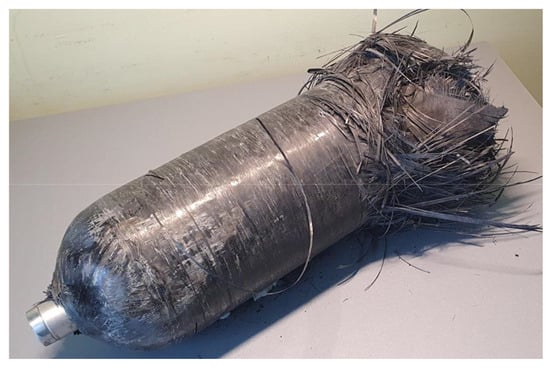
Figure 1.
The composite cylinder used for pressurized gas storage.
2.2. Pyrolysis Process and Composite Lamination
The first task carried out in this work was to test the composite’s resistance to the air and nitrogen atmosphere and check the surface quality of the obtained recycled fibers. For this purpose, TG (thermogravimetry) tests were carried out by heating composite scrap at 140, 400, 500, 600, and 700 °C in an air and nitrogen atmosphere. This study aimed to determine the resistance of fibers to storage at high temperatures over time.
Pyrolysis at an experimentally determined temperature of the composite was carried out in an oven (tunnel furnace with a quartz chamber with an argon flow of 50 mL/min) at a temperature of 460 °C. The heating rate was 10 °C/min, and after reaching the set temperature, the isothermal process time was 60 min. For the comparison and verification of the effect of conditions on the thermal process, pyrolysis was performed in both an inert atmosphere (nitrogen) and an oxidizing atmosphere (air).
The recovered fibers were cleaned in two stages using an ultrasonic cleaner, (Elmasonic S130H, Łomża, Poland) first for 20 min in acetone (15 mL/1 g sample) and then for another 20 min in distilled water (15 mL/1 g sample). In the next step, the fibers were dried in a vacuum dryer at 80 °C for 60 min. The dried fibers were cut into pieces about 3–4 cm long, some of which were delaminated into finer strands (Figure 2).
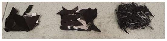
Figure 2.
Carbon fibers recovered after annealing in nitrogen atmosphere (left), air (center), and nitrogen after additional delamination into finer strands (right).
New composite laminates containing the recovered fibers were made in silicone molds using Epidian 652 (Ciech, Nowa Sarzyna, Poland) epoxy resin and an IDA hardener in a ratio of 100:50. A total of 6 types of composite samples were created containing fibers after pyrolysis in air and nitrogen, which were divided into 3 groups: The first two had a fiber-to-matrix ratio of 60:40 and 40:60, while the third group also had a ratio of 60:40, but the fibers used were delaminated into finer strands. The fabricated wafer laminates were gravity-compressed in molds and left for 24 h until fully cross-linked. Finally, the samples were cut into cuboidal pieces suitable for mechanical testing. A summary of the breakdown of the samples used in this study is shown in Table 1.

Table 1.
Description of composites created using recycled fibers.
2.3. Methods
In order to determine the effect of atmosphere and temperature during the pyrolysis process on the quality of the resulting fibers, thermal analysis tests and microscopic examinations were carried out using samples from the composite cylinder. Mechanical tests showing strength properties were carried out on the created laminates containing the fibers generated through the thermal recycling process.
2.3.1. Thermogravimetry Analysis (TGA)
The thermal analysis of the composites was carried out using DISCOVERY’s TGA550 apparatus (New Castle, DE, USA). The tests were carried out at a constant heating rate of 10 °C/min in an atmosphere of air and nitrogen. After reaching the final temperatures, namely 140, 400, 500, 600, and 700 °C, the samples were additionally held under isothermal conditions for 60 min. In the course of the research, an attempt was made to capture the temperature at which the thermal degradation process is sufficiently rapid to release the fibers while not damaging the fiber surface too rapidly.
2.3.2. Morphological Analysis by Scanning Electron Microscope (SEM)
Composite samples containing the released carbon fibers recovered after thermogravimetric analysis were subjected to microscopic examination using a Thermo Fisher Scientific Phenom Pharo scanning electron microscope (SEM) (Waltham, MA, USA). The aim of this study was to visualize the degree of fiber release from the matrix, investigate the surface quality after annealing, and compare the differences between the samples prepared under two atmospheres: nitrogen and air. Magnifications of 500 and 25,000 were used for all samples, and additional magnifications for temperature ranges of interest (400, 500, and 700 °C) were included.
2.3.3. Mechanical Strength—Bending Tests
The strength features of the static bending test were assessed according to the recommendations of the EN ISO 178 standards [29]. The tests were carried out on a Zwick/Roell 1445 RetroLine (Ulm, Germany) testing machine, series no.: 736.695. A preload of 0.1 MPa was set, the bending modulus speed was 2 mm/min, the test speed was 10 mm/min, and the support spacing was 64 mm. A normative specimen shape was used, with dimensions of 80 × 10 × 4 mm. The test was conducted at 23 °C and 51% RH (6 samples of each type were tested). Flexural testing involves both tensile and compressive stresses, as well as the interlaminar shear stress that is present in composite materials, and it is used to determine the durability of the interfacial bond in the composite. The bending test and the shear stress test are the best methods for testing delamination in a composite.
2.3.4. Dynamic Mechanical Analysis (DMA)
Dynamic mechanical analysis testing was carried out on a DISCOVERY DMA850 (New Castle, DE, USA) for cyclic bending. Samples of the created composite laminates using recycled fibers from the pyrolysis process were used. The dimensions of the samples were 60 × 10 × 4 mm. The reference for the composites was the cross-linked epoxy resin used to prepare the other samples. All analyses were performed in the air atmosphere, in the temperature range between 10 and 150 °C with a constant heating rate of 10 °C/min. The initial force was 5 N, amplitude 50 μm, frequency 10 Hz (3 samples for each type).
3. Results and Discussion
3.1. Thermal Decomposition/Stability of Composites
By carrying out a thermogravimetry study, it was possible to determine the thermal stability of the composite under various environmental conditions. The curves obtained, including the course of the first derivative after temperature, are shown in Figure 3, Figure 4, Figure 5, Figure 6 and Figure 7. For comparison purposes, the characteristic temperatures of the start and end of matrix decomposition and the amount of remaining material for each sample are noted in Table 2.
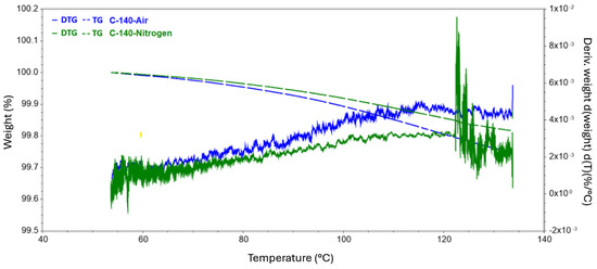
Figure 3.
Results of TG tests carried out to reach 140 °C conducted in a nitrogen and air atmosphere.
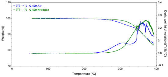
Figure 4.
Results of TG tests carried out to reach 400 °C conducted in a nitrogen and air atmosphere.

Figure 5.
Results of TG tests carried out to reach 500 °C conducted in a nitrogen and air atmosphere.
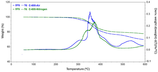
Figure 6.
Results of TG tests carried out to reach 600 °C conducted in a nitrogen and air atmosphere.
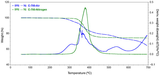
Figure 7.
Results of TG tests carried out to reach 700 °C conducted in a nitrogen and air atmosphere.
Table 2.
Summary of characteristic temperatures of the start and end of matrix decomposition and the amount of remaining material for each sample.
The analysis carried out up to a temperature of 140 revealed a slight decrease in the mass of the sample, while the release of the practical fibers itself had not yet begun. All changes in this regard were probably related to the evaporation of moisture from the surface of the test samples. In the second series of measurements, where the target temperature was 400 °C, the process of rapid mass loss started at 304 °C and 251 °C for the nitrogen and air atmospheres, respectively. The weight loss of the samples did not differ specifically between the atmospheres used and was around 15%. In the case of a measurement where the final temperature was 500 °C, the first greater difference was observed in the remaining mass of the tested samples. The residual mass of the composite annealed in nitrogen was 80.837%, while that of the sample in the oxidizing atmosphere was 77.301%. The temperature for both samples at which the rapid change in mass loss stopped, and the process became more stable was also recorded. Subsequently, for temperatures of 600 °C and 700 °C, greater mass loss was observed, involving the appearance of new matrix decomposition stages and increasingly significant discrepancies in the amount of residual substance between the atmospheres used. For 600 °C, the difference was 7.774 percentage points, while for 700 °C, the corresponding difference was 9.514 percentage points.
Of interest in the context of this analysis is the sheer characterization of the intensity of the various stages of matrix decomposition. For each sample, the inert atmosphere had a delayed effect on the onset of the mass loss process. Moreover, the degradation process in nitrogen had a strongly enhanced intensity in the region of 380–395 °C, which was best documented for the sample annealed to 700 °C, while in the case of the air atmosphere, there was a breakdown of the decomposition intensity into several stages. Notably, the range above 462 °C, where the next two visible stages of decomposition began, was only considered for the sample in the air atmosphere. In the case of an inert atmosphere, no visible changes were observed in the derivative curve obtained for the mass distribution. This fact is most likely indicative of the onset of degradation of the carbon fibers themselves in the presence of an oxidizing environment and high temperature. Degradation under an air atmosphere is much more rapid compared to the process carried out in nitrogen. The oxygen present in the air atmosphere causes the oxidation of the matrix as well as the decomposition of its products to the oxides of the matrix-building elements (including their size). In the case of pyrolysis in a nitrogen atmosphere, the decomposition process is more gradual, and liquid decomposition products such as phenolic and aromatic compounds or esters, acids, and benzyl compounds may also be formed [5,11,30].
A further stage of the study involved analyzing the isotherms formed from holding the samples at a specific temperature. The resulting curves are shown in a summary form in Figure 8 and Figure 9. Table 3 details the annealing weight loss and residual material for each of the tested samples. The effect of holding the sample at 140 °C resulted in a slight loss of mass but reached more than double that of nitrogen in the case of the air atmosphere. At 400 °C, the weight loss was 4.6% and 6.1%, respectively, relative to the initial value, but the residual mass differed by only about 0.4%. At 500 °C, a greater difference was observed due to the atmospheres used. In nitrogen, the decrease in mass was less than that obtained at 400 °C. This fact may indicate that a greater degree of matrix decomposition occurred before reaching 500 °C. In contrast, in atmospheres involving oxygen, the mass loss was at a similar level to that occurring at 400 °C. At 600 °C, a significant decrease of about 20% was recorded in the air atmosphere, and consequently, 50% of the initial mass of the composite remained at the end of the test. In a nitrogen atmosphere, the mass loss occurred to a much lesser extent, at a level close to the values achieved at 400 and 500 °C. A holding temperature of 700 °C in air resulted in a sample loss of almost 64%, thus reducing the remaining mass to less than 1%. In contrast to this is the result obtained for annealing the composite in the presence of nitrogen, where the degree of mass loss was 0.223% and the residual mass was not very different from that obtained at 600 °C, i.e., 74.203%.
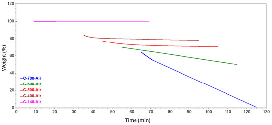
Figure 8.
Isotherms generated at different temperatures in an air atmosphere.
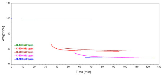
Figure 9.
Isotherms generated at different temperatures in a nitrogen atmosphere.
Table 3.
Values of mass losses considering the isotherms generated in the tested atmospheres.
Since the temperature of the end of the mass distribution for the samples was in the range between 456 and 462 °C, we also took a closer look at the isotherms formed for temperatures of 400 and 500 °C. The resulting curves, along with a plot of the first derivatives after time, are shown in Figure 10 and Figure 11. It is easy to see that the greatest changes occurred during the first ten minutes after reaching the set temperature. This phenomenon is particularly evident for the sample annealed at 500 °C in an air atmosphere.
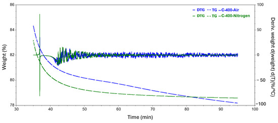
Figure 10.
Results of TGA tests during isothermal heating at 400 °C carried out in a nitrogen and air atmosphere.
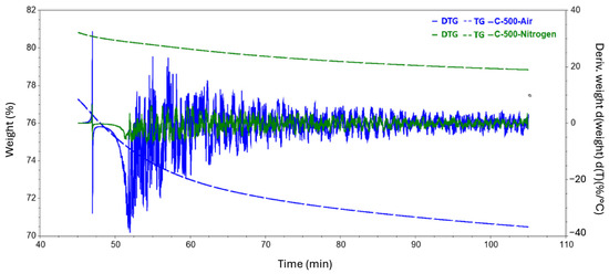
Figure 11.
Results of TGA tests during isothermal heating at 500 °C carried out in a nitrogen and air atmosphere.
Based on the analyses performed and the established temperature values at which the rate of change in the mass of the samples stabilized, 460 °C was determined to be a suitable temperature for the pyrolysis of CFRPs obtained from a waste composite cylinder (the obtained value is close to the optimum distribution temperatures referred to by the authors of other publications [11,23,31]). This was considered to be the smallest temperature at which the fibers would be freely released without rapid transformations. It is also the temperature that will allow for a reasonably rapid release, which, on an industrial scale, will reduce the time it takes to anneal the fibers, thereby reducing the energy supplied to the furnace.
3.2. Morphological Analysis
The samples recovered after thermogravimetric analysis were examined under a scanning electron microscope. The aim of this examination was to visualize the process of fiber release from the resin, assess the surface quality after annealing, and compare the differences resulting from the specific atmosphere used during thermogravimetric analysis. The results of the SEM morphological analysis are presented below in the form of the images taken (Figure 12, Figure 13, Figure 14, Figure 15, Figure 16, Figure 17, Figure 18 and Figure 19). Each set of images in the figures below shows two samples after TGA analysis carried out under isothermal conditions at a specific holding temperature. The left column (A,C) shows the samples held in a nitrogen atmosphere, and the right column (B,D) shows samples in an oxidizing atmosphere. Each figure contains successive magnifications ranging from 500× to 150,000×.
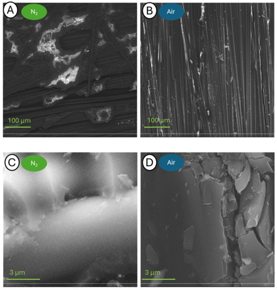
Figure 12.
Pictures of samples C-140-N (A,C) and C-140-A (B,D) taken at a blow-up of 500× (A,B) and 25,000× (C,D).
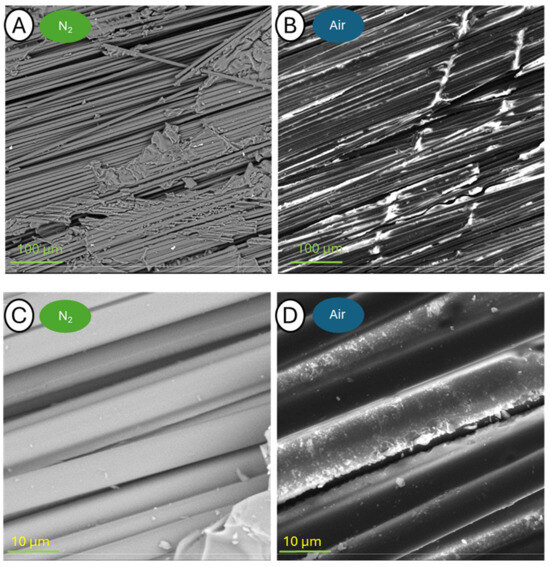
Figure 13.
Pictures of samples C-400-N (A,C) and C-400-A (B,D) taken at a blow-up of 500× (A,B) and 5000× (C,D).
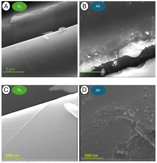
Figure 14.
Pictures of samples C-400-N (A,C) and C-400-A (B,D) taken at a blow-up of 25,000× (A,B) and 150,000× (C,D).
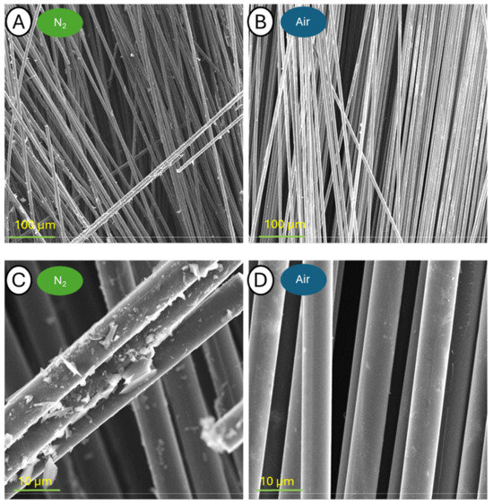
Figure 15.
Pictures of samples C-500-N (A,C) and C-500-A (B,D) taken at a blow-up of 500× (A,B) and 5000× (C,D).

Figure 16.
Pictures of samples C-500-N (A,C) and C-500-A (B,D) taken at a blow-up of 25,000× (A,B) and 150,000× (C,D).
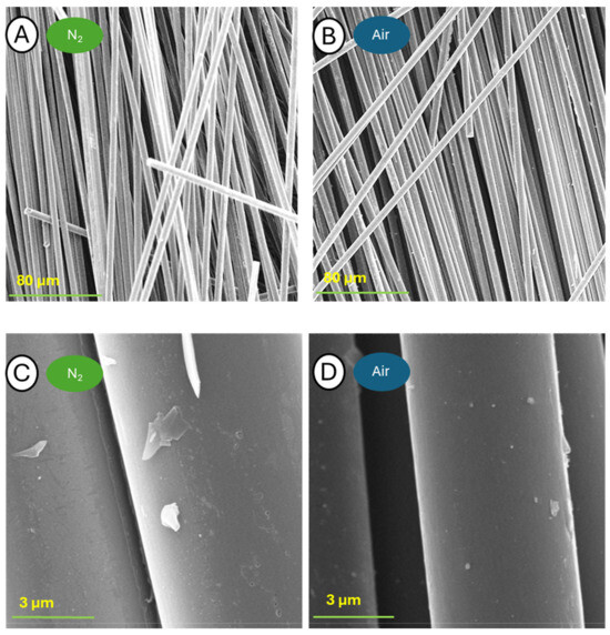
Figure 17.
Pictures of samples C-600-N (A,C) and C-600-A (B,D) taken at a blow-up of 1000× (A,B) and 25,000× (C,D).
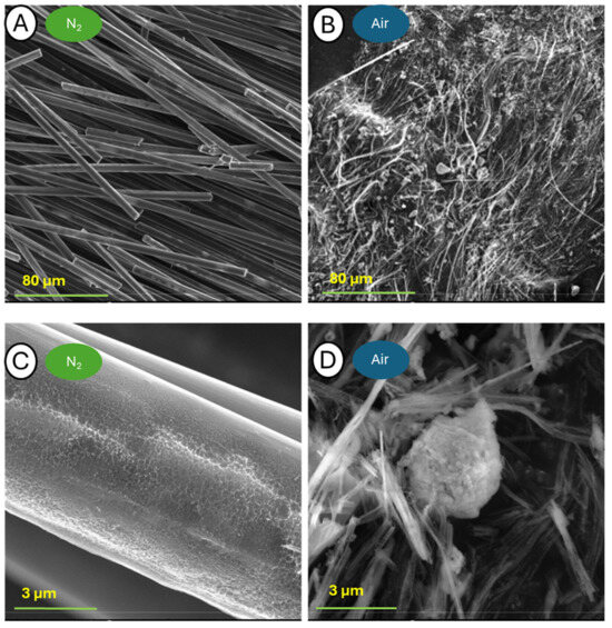
Figure 18.
Pictures of samples C-700-N (A,C) and C-700-A (B,D) taken at a blow-up of 500× (A,B) and 25,000× (C,D).
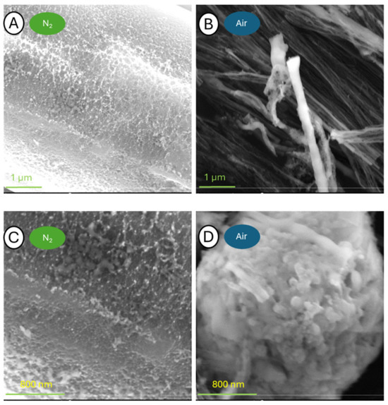
Figure 19.
Pictures of samples C-700-N (A,C) and C-700-A (B,D) taken at a blow-up of 50,000× (A,B) and 100,000× (C,D).
The samples annealed at 140 °C have a virtually intact structure. At 500× magnification, a great amount of resin residue can be seen on the fibers, especially on the sample from the analysis in nitrogen. The brighter areas in the images of the samples analyzed in nitrogen also indicate the presence of resin on the fiber surface, and using the Secondary Electron Detector (SED), it can be seen that the convex areas are brighter than the flat ones. Further approximations show fibers glued together, and it is not possible to distinguish the individual fibers released. The only noticeable difference between the samples annealed in the presence of different atmospheres is the presence of cracks on the surface of the composite in contact with the oxidizing environment.
The samples annealed at 400 °C are characterized by relatively large fragments of resin residue on the fiber surface. The use of the SED allowed more details to be identified. In the case of larger blow-up images, it is possible to observe the effective beginning of the fiber release process, which can be singularly detailed. It is noteworthy that the fiber topography itself appears to be intact after thermogravimetry testing in a nitrogen atmosphere, whereas those analyzed in the air have small depressions on the surface.
Microscopic observations of both samples annealed at 500 °C at the lowest magnification of 500× show a single, released carbon fiber. Higher magnifications, however, revealed many small epoxy resin residues on the fibers released in the nitrogen atmosphere, but importantly, no damage was observed. In the case of the sample held in an oxidizing atmosphere, the fibers were almost completely freed from the resin. It is worth noting, however, that the first defects appeared on their surface, already visible at 25,000× magnification and detailed at higher image zooms.
The samples pyrolyzed at 600 °C are characterized by the complete release of fibers from the matrix. At higher image blow-ups, only trace residues of matrix decomposition products are observed. The surface topography mostly exhibits defects in both cases. The sample after TGA analysis in nitrogen at the last two magnifications shows a large number of small cracks in many places. The sample subjected to TGA in oxygen is already characterized by a high level of imperfection density at 12,000× magnification. Enlargement to 100,000× particularly showed the virtually complete destruction of the fiber surface.
The greatest differences in surface morphology were observed when tests were conducted at 700 °C. The first magnification showed a significant difference between the two samples. While in the case of the sample analyzed in a nitrogen atmosphere, the appearance and shape of the fibers were preserved, the sample after TG analysis in the air was completely degraded. In the case of the fibers annealed in nitrogen, the structure in the volume was preserved, while the entire surface exhibited severe defects. A photograph of the sample held in air taken at 1000× magnification reveals only the delaminated fiber remnants tangled together. Larger blow-ups reveal that the fibers were broken and torn throughout. With an image zoom of 100,000×, the individual graphite lobes that build up the individual carbon fibers can be seen.
3.3. Mechanical Strength—Flexural Tests
The mechanical properties of the fabricated composites were determined using a static bending test. A summary of the stress–strain curves obtained for sample specimens from each test is shown in Figure 20. Table 4 shows the results of the average values of Young’s modulus in bending, bending strength, and maximum strain.
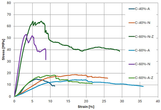
Figure 20.
Stress–strain diagram obtained for bending test of composite specimens.
Table 4.
Stress-bending results of composite specimens.
The flexural strength of the obtained laminates is also significantly lower than the values reported by manufacturers of new, non-recycled fibers. This fact may have been influenced by the phenomenon of poor seepage of fibers through the matrices, resulting in a deterioration of mechanical properties. Comparing the samples annealed in different atmospheres, it can be seen that composites containing the fibers recovered in the presence of nitrogen exhibit visibly higher strength in all cases. The highest values were achieved for materials containing 60% fibers. In addition, the process of grinding the fibers recovered from the pyrolysis process had a positive effect on the extensibility properties. This relationship is evident in the case of both nitrogen and air application, as an increase in tensile strength by 21% and 28%, respectively, was obtained relative to samples in which the fibers were not fragmented.
Analyzing the strain values of the samples, it can be seen that fibers recovered in an air atmosphere are characterized by higher strain, making them more flexible. This relationship is evident for the obtained values of modulus, where composites containing the recovered fibers in the presence of an inert atmosphere are characterized by higher values of this parameter relative to their counterparts derived from annealing in an oxidizing atmosphere. The samples characterized by the highest values of modulus were C-60%-N and C-60%-N-Z, reaching values of 2051.7 and 1834.7 MPa.
3.4. Results of Dynamic Mechanical Analysis (DMA)
The results of the DMA measurements are presented in the form of summary plots of the conservative modulus, loss modulus, and loss factor for each type of composite (Figure 21 and Figure 22). All graphs were plotted as a function of temperature. The summarized collection of the values of the storage modulus, the loss modulus of the samples obtained for room temperature (22 °C), and the temperature at the maximum value of the tangent of the angle of mechanical loss are included in Table 5.
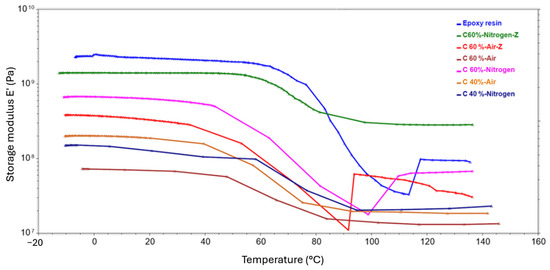
Figure 21.
DMA test results showing the temperature dependence of the storage modulus obtained for composite samples.
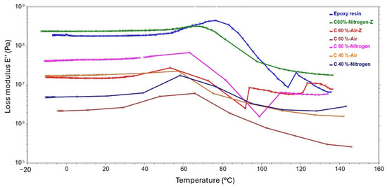
Figure 22.
DMA test results showing the temperature dependence of the loss modulus obtained for composite samples.
Table 5.
DMA test values for the composites.
The graphs for the storage modulus showed a downward trend with increasing temperature in all cases. Worth noting is the point at which the function becomes inflected, and there is then a sharp drop in modulus. This point was detected in the temperature range from 40 °C to 60 °C, depending on the sample, and is related to the glass transition temperature. It is also usually the maximum temperature at which the material can operate while retaining all its mechanical properties. Among the samples pyrolyzed in a nitrogen atmosphere, a laminate with 60% ground fiber content achieved the highest storage modulus. The highest modulus of the samples recovered in the air was achieved by a laminate with 60% shredded fiber content. Comparing samples with the same carbon content and prepared in the same way, the better values of the conservative modulus were obtained by laminates with fibers pyrolyzed in the presence of an inert atmosphere. Furthermore, for both atmospheres, the effect of fragmenting the fibers prior to composite formation increased the modulus. It is noteworthy that all composites obtained lower values than the reference sample, which was a cross-linked epoxy resin. This fact can be explained by the occurrence of insufficient bonding at the fiber–matrix interface, and the presence of defects.
The curve of the loss modulus as a function of temperature is similar in character to that of the conservative modulus. This relationship was observed for all samples, with the onset of a sharp increase also observed in the 40–60-degree range. Similarly, the highest values were obtained for the sample containing 60% shredded fibers from the recycling process carried out in nitrogen and for the composite with 60% recycled shredded fibers in air. The graphs also show characteristic peaks that occur for the glass transition temperature of the sample, which is the temperature at which the rigid composite becomes more ductile. Table 6 presents the determined values of the glass transition temperature for each of the laminates and for the resin. The glass transition temperatures are indirectly related to the values of the loss modulus; the higher the loss modulus, the higher the glass transition temperature. An exception is the sample with 60% fiber content obtained in an air atmosphere, which had the highest glass transition temperature of 65.7 °C among the laminates. In contrast, the pure resin sample had the highest glass transition temperature overall.
Table 6.
Values of the glass transition temperature for each of the laminates and resin.
The tan δ diagrams (Figure 23) as a function of temperature reveal to what extent the energy in the material is dissipated under the applied stress. With the exception of specimen C-60%-A-Z, the graphs obtained have a characteristic appearance with a single, distinct peak in the vicinity of the glass transition temperature. The analysis can therefore be performed by comparing tan δ values before and after the glass transition temperature. High energy absorption before the glass transition temperature was achieved by the samples made of fibers recycled in a nitrogen atmosphere, with the exception of the sample with lower fiber content. Among the fiber laminates heated in air, the sample with 40% fiber content showed the highest energy absorption. When the glass transition temperature was reached, a slight decrease in function was observed in the graphs of the fiber laminates recovered in nitrogen and for the C40P sample. This demonstrates the good energy absorption properties in relation to stress. The graph of sample C-60%-A after reaching the glass transition temperature is characterized by a sharp decrease, which indicates poor energy absorption properties at higher temperatures. The graph obtained for the C-60%-A-Z sample after the glass transition indicates an initial decrease and then the curve is almost constant, followed by a rapid increase. This tendency is probably due to partial damage to the sample during the test.
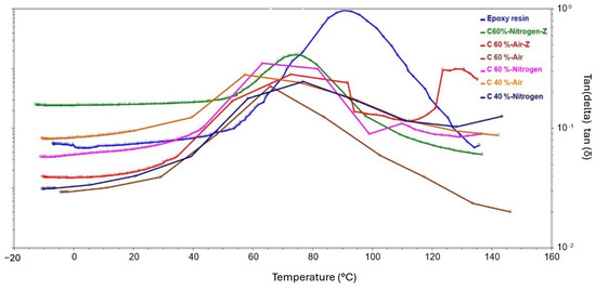
Figure 23.
DMA test results showing the temperature dependence of the loss factor (tan δ) obtained for composite samples.
4. Conclusions
In conclusion, this study investigated the possibility of recycling carbon fiber-reinforced composites by pyrolysis. The thermal analysis of the composite samples made it possible to investigate the influence of temperature and atmosphere on the process of fiber release from the matrix. The thermogravimetry study revealed a decomposition mechanism of the resin matrix that involved several stages, and a strongly degrading effect of the oxidation process on the carbon fibers particularly occurring at high temperatures. Microscopic observations of the samples recovered after the test showed released fibers in most cases, but the fibers annealed in the presence of air showed a significantly degraded surface quality relative to the samples pyrolyzed in nitrogen. Reaching a temperature of 700 °C and isothermally holding the samples in the presence of oxygen resulted in the almost complete degradation of the fibers, as evidenced by the results from the thermal analysis and the images taken with a scanning electron microscope. The tests carried out made it possible to select a pyrolysis temperature of 460 °C and a time of 60 min to carry out further operations. Recycling should be carried out at the lowest possible temperature at which all composite constituents except the fibers are broken down into gaseous and solid products. The use of temperatures higher than 460 °C is energetically unjustified and is associated with an increased risk of fiber deterioration.
Analyzing the obtained results of mechanical properties for composites made using recycled fibers, it can be concluded that the strength parameters obtained for the samples deviate from the expected values. This fact may have been influenced by the poor level of fiber permeation and the formation of air bubbles and other defects after cross-linking. This fact illustrates the need for additional steps in the preparation of composites containing recovered fibers, such as pressing. Leading the way, however, is the dependence on achieving higher strength parameters for composites containing fibers recovered in nitrogen. The inert atmosphere proved to be crucial in protecting the fibers from excessive surface deterioration. Samples containing 60% recycled carbon fiber, pyrolyzed in nitrogen, exhibited an average 247% higher bending strength compared to samples containing 40% recycled carbon fiber and 260% higher density compared to samples containing 60% recycled carbon fiber in an air atmosphere.
Analogous conclusions were drawn from DMA tests in which samples were subjected to cyclic bending. An additional relationship observed was that the fragmentation of the recovered fibers facilitated the formation of better adhesion bonds at the fiber–matrix interface, which also resulted in an increase in the strength of the composites. It is worth mentioning, however, that thermally recovered fibers can have a significantly altered surface structure relative to virgin fibers. Physiochemical modification (e.g., re-silanization) may be necessary to achieve better adhesion with the epoxy matrix when reusing the recyclate. However, this research proved the effectiveness of the thermal recycling process of CFRP composites itself and provided insights for further developments in the reuse of materials considered waste and the policy of sustainability itself.
Samples containing 60% recycled carbon fiber, pyrolyzed in nitrogen, exhibited a higher storage modulus compared to samples containing 40% recycled carbon fiber (an increase of 537%) and a higher density compared to samples containing 60% recycled carbon fiber in an air atmosphere (an increase of 426%). The characteristics of the resulting material changed from a densified composite to a porous nonwoven fabric, where the fibers and resin formed a composite matrix with a high content of open porosity.
Recycling carbon fibers from composite materials has significant environmental implications, primarily in reducing waste and minimizing the carbon footprint associated with producing virgin fibers. Recycling carbon fiber-reinforced composites helps divert waste from landfills. This is crucial as CFRPs are challenging to dispose of due to their durability and resistance to degradation.
Author Contributions
Conceptualization, P.S. and R.T.; methodology, P.S. and R.T.; software, P.S. and R.T.; validation, P.S. and R.T.; formal analysis, P.S. and R.T.; investigation, P.S. and R.T.; resources P.S. and R.T.; data curation, P.S. and R.T.; writing—original draft preparation, P.S. and R.T.; writing—review and editing, P.S. and R.T.; visualization, P.S. and R.T.; supervision, P.S. and R.T.; project administration, P.S. and R.T.; funding acquisition, P.S. and R.T. All authors have read and agreed to the published version of the manuscript.
Funding
This work was supported from the subsidy of the Ministry of Education and Science for the AGH University of Krakow (Project No. 16.16.160.557).
Data Availability Statement
The data used to support the findings of this study are included within the article. Additional data are available from the corresponding author upon request.
Conflicts of Interest
The authors declare no conflicts of interest.
References
- Zhang, J.; Chaisombat, K.; He, S.; Wang, C.H. Glass/Carbon Fibre Hybrid Composite Laminates for Structural Applications in Automotive Vehicles. In Sustainable Automotive Technologies 2012; Springer: Berlin/Heidelberg, Germany, 2012; pp. 69–74. [Google Scholar]
- Rajak, D.K.; Wagh, P.H.; Linul, E. Manufacturing Technologies of Carbon/Glass Fiber-Reinforced Polymer Composites and Their Properties: A Review. Polymers 2021, 13, 3721. [Google Scholar] [CrossRef] [PubMed]
- Park, S.-J.; Kim, B.-J. Carbon Fibers and Their Composites; Springer: Dordrecht, The Netherlands, 2015; pp. 275–317. [Google Scholar]
- Carbon Fiber Reinforced Plastic Market Size, Share & Trends Analysis Report by Raw Material, by Product (Thermosetting, Thermoplastic), by Application, by Region, and Segment Forecasts, 2023–2030. Available online: https://www.grandviewresearch.com/industry-analysis/carbon-fiber-market (accessed on 18 August 2024).
- Chen, P.-Y.; Feng, R.; Xu, Y.; Zhu, J.-H. Recycling and Reutilization of Waste Carbon Fiber Reinforced Plastics: Current Status and Prospects. Polymers 2023, 15, 3508. [Google Scholar] [CrossRef] [PubMed]
- Lunetto, V.; Galati, M.; Settineri, L.; Iuliano, L. Sustainability in the Manufacturing of Composite Materials: A Literature Review and Directions for Future Research. J. Manuf. Process. 2023, 85, 858–874. [Google Scholar] [CrossRef]
- Griffith, D.T.; Cao, D.; Lu, H.; Qian, D. Composite Materials in Wind Energy: Design, Manufacturing, Operation, and End-of-Life. IOP Conf. Ser. Mater. Sci. Eng. 2023, 1293, 012002. [Google Scholar] [CrossRef]
- Lefeuvre, A.; Garnier, S.; Jacquemin, L.; Pillain, B.; Sonnemann, G. Anticipating In-Use Stocks of Carbon Fiber Reinforced Polymers and Related Waste Flows Generated by the Commercial Aeronautical Sector until 2050. Resour. Conserv. Recycl. 2017, 125, 264–272. [Google Scholar] [CrossRef]
- Isa, A.; Nosbi, N.; Che Ismail, M.; Md Akil, H.; Wan Ali, W.F.F.; Omar, M.F. A Review on Recycling of Carbon Fibres: Methods to Reinforce and Expected Fibre Composite Degradations. Materials 2022, 15, 4991. [Google Scholar] [CrossRef]
- Asmatulu, E.; Twomey, J.; Overcash, M. Recycling of Fiber-Reinforced Composites and Direct Structural Composite Recycling Concept. J. Compos. Mater. 2014, 48, 593–608. [Google Scholar] [CrossRef]
- Karuppannan Gopalraj, S.; Kärki, T. A Review on the Recycling of Waste Carbon Fibre/Glass Fibre-Reinforced Composites: Fibre Recovery, Properties and Life-Cycle Analysis. SN Appl. Sci. 2020, 2, 433. [Google Scholar] [CrossRef]
- Pickering, S.J. Recycling Technologies for Thermoset Composite Materials—Current Status. Compos. Part A Appl. Sci. Manuf. 2006, 37, 1206–1215. [Google Scholar] [CrossRef]
- Pakdel, E.; Kashi, S.; Varley, R.; Wang, X. Recent Progress in Recycling Carbon Fibre Reinforced Composites and Dry Carbon Fibre Wastes. Resour. Conserv. Recycl. 2021, 166, 105340. [Google Scholar] [CrossRef]
- Song, H.; He, G.; He, Y.; Huang, L.; Gao, Z.; Zhang, R.; Zhang, L.; Liu, H.; Liu, C. Effects of Surface Modification on Mechanical Properties and Electromagnetic Interference Shielding Properties of Carbon Fiber/Silk Fiber Hybrid Composites. Polym. Compos. 2024, 45, 10276–10289. [Google Scholar] [CrossRef]
- He, Y.; Chen, Q.; Wu, D.; Zhou, M.; Wang, T.; Lu, C.; Zhang, L.; Liu, H.; Liu, C. Effect of Multiscale Reinforcement by Fiber Surface Treatment with Polyvinyl Alcohol/Graphene Oxide/Oxidized Carbon Nanotubes on the Mechanical Properties of Reinforced Hybrid Fiber Composites. Compos. Sci. Technol. 2021, 204, 108634. [Google Scholar] [CrossRef]
- Witik, R.A.; Teuscher, R.; Michaud, V.; Ludwig, C.; Månson, J.-A.E. Carbon Fibre Reinforced Composite Waste: An Environmental Assessment of Recycling, Energy Recovery and Landfilling. Compos. Part A Appl. Sci. Manuf. 2013, 49, 89–99. [Google Scholar] [CrossRef]
- Oliveux, G.; Dandy, L.O.; Leeke, G.A. Current Status of Recycling of Fibre Reinforced Polymers: Review of Technologies, Reuse and Resulting Properties. Prog. Mater. Sci. 2015, 72, 61–99. [Google Scholar] [CrossRef]
- Schinner, G.; Brandt, J.; Richter, H. Recycling Carbon-Fiber-Reinforced Thermoplastic Composites. J. Thermoplast. Compos. Mater. 1996, 9, 239–245. [Google Scholar] [CrossRef]
- Ozdemir, T.; Deitzel, J.M.; Crane, R.; Yarlagadda, S.; Blackwell, C.; Davis, M.; Emmerich, R.; Heider, D. Carbon Fiber Composites Recycling Technology Enabled by the TuFF Technology. Recycling 2024, 9, 11. [Google Scholar] [CrossRef]
- Smoleń, J.; Olesik, P.; Jała, J.; Adamcio, A.; Kurtyka, K.; Godzierz, M.; Kozera, R.; Kozioł, M.; Boczkowska, A. The Use of Carbon Fibers Recovered by Pyrolysis from End-of-Life Wind Turbine Blades in Epoxy-Based Composite Panels. Polymers 2022, 14, 2925. [Google Scholar] [CrossRef] [PubMed]
- Ren, Y.; Xu, L.; Shang, X.; Shen, Z.; Fu, R.; Li, W.; Guo, L. Evaluation of Mechanical Properties and Pyrolysis Products of Carbon Fibers Recycled by Microwave Pyrolysis. ACS Omega 2022, 7, 13529–13537. [Google Scholar] [CrossRef] [PubMed]
- Onwudili, J.A.; Miskolczi, N.; Nagy, T.; Lipóczi, G. Recovery of Glass Fibre and Carbon Fibres from Reinforced Thermosets by Batch Pyrolysis and Investigation of Fibre Re-Using as Reinforcement in LDPE Matrix. Compos. B Eng. 2016, 91, 154–161. [Google Scholar] [CrossRef]
- Wei, Y.; Hadigheh, S.A. Enhancing Carbon Fibre Recovery through Optimised Thermal Recycling: Kinetic Analysis and Operational Parameter Investigation. Mater. Today Sustain. 2024, 25, 100661. [Google Scholar] [CrossRef]
- Deng, J.; Xu, L.; Zhang, L.; Peng, J.; Guo, S.; Liu, J.; Koppala, S. Recycling of Carbon Fibers from CFRP Waste by Microwave Thermolysis. Processes 2019, 7, 207. [Google Scholar] [CrossRef]
- Hao, S.; He, L.; Liu, J.; Liu, Y.; Rudd, C.; Liu, X. Recovery of Carbon Fibre from Waste Prepreg via Microwave Pyrolysis. Polymers 2021, 13, 1231. [Google Scholar] [CrossRef] [PubMed]
- Meyer, L.O.; Schulte, K.; Grove-Nielsen, E. CFRP-Recycling Following a Pyrolysis Route: Process Optimization and Potentials. J. Compos. Mater. 2009, 43, 1121–1132. [Google Scholar] [CrossRef]
- ISO 11119-3:2013; Gas Cylinders—Refillable Composite Gas Cylinders and Tubes—Design, Construction and Testing—Part 3: Fully Wrapped Fibre Reinforced Composite Gas Cylinders and Tubes Up to 450 L with Non-Load-Sharing Metallic or Non-Metallic Liners. International Organization for Standardization: Geneva, Switzerland, 2013.
- EN 12245:2009+A1:2011; Transportable Gas Cylinders—Fully Wrapped Composite Cylinders. European Committee for Standardization: Brussels, Belgium, 2011.
- ISO 178:2019; Plastics—Determination of Flexural Properties. International Organization for Standardization: Geneva, Switzerland, 2019.
- Yatim, N.M.; Shamsudin, Z.; Shaaban, A.; Sani, N.A.; Jumaidin, R.; Shariff, E.A. Thermal Analysis of Carbon Fibre Reinforced Polymer Decomposition. Mater. Res. Express 2020, 7, 015615. [Google Scholar] [CrossRef]
- Matielli Rodrigues, G.G.; Faulstich de Paiva, J.M.; Braga do Carmo, J.; Botaro, V.R. Recycling of Carbon Fibers Inserted in Composite of DGEBA Epoxy Matrix by Thermal Degradation. Polym. Degrad. Stab. 2014, 109, 50–58. [Google Scholar] [CrossRef]
Disclaimer/Publisher’s Note: The statements, opinions and data contained in all publications are solely those of the individual author(s) and contributor(s) and not of MDPI and/or the editor(s). MDPI and/or the editor(s) disclaim responsibility for any injury to people or property resulting from any ideas, methods, instructions or products referred to in the content. |
© 2024 by the authors. Licensee MDPI, Basel, Switzerland. This article is an open access article distributed under the terms and conditions of the Creative Commons Attribution (CC BY) license (https://creativecommons.org/licenses/by/4.0/).