1. Introduction
Carbon fiber-reinforced plastic (CFRP) materials have remarkable specific mechanical properties, especially regarding the modulus-to-weight and strength-to-weight ratios. This explains their popularity and their increasing use in the transportation sector (aeronautics, rail and automotive), where reducing the weight of a structure enables significant energy savings.
Despite the continuous improvement of molding methods to produce laminated parts, a trimming operation is still necessary to remove excess material on part edges to achieve the functional dimensions required by specifications. Machining methods commonly used for metal are tested on composite materials. Laser machining was investigated by many researches and it was found that this method induces significant thermal damage to the material [
1,
2,
3]. The cutting water jet was also investigated and it was found to introduce a very poor surface finish of the trimmed components [
4,
5]. Conventional trimming using cutting tools remains the simplest and least detrimental method for the material and will be studied in this work.
Unlike metals, the machining of composites is difficult and inevitably generates defects such as delamination, fiber pull-out, matrix cracking, and plastic deformation on the machined edges [
6,
7]. These defects depend substantially on cutting parameters and machining configuration [
8]. High cutting speed and low feed rate is the best combination in terms of surface integrity and surface roughness for CFRP machining [
6,
9]. Other authors confirm the same conclusion and also report that cutting forces are, as well, lowest for this combination [
10,
11,
12,
13,
14,
15,
16]. The fiber orientation also has an influence on the surface finish. Pecat et al. [
17] found that a smooth surface was seen when milling with 0° and +45° orientations, while under −45° and 90° their micrographs showed severe damage in the form of cracks. Chatelain et al. [
18] also studied the effect of the ply orientation on roughness for the trimming process of quasi-isotropic aerospace CFRP laminates. They found that each ply orientation had its own “typical” roughness profile. The surface roughness across the laminate was measured for different fiber orientations (0°, 45°, 90° and −45°) of the CFRP laminate using the longitudinal method. The −45° ply orientation showed the worst surface roughness. Other research also confirmed that the worst surface roughness is observed on the plies oriented at −45° [
15,
18,
19].
As with mechanical damage, cutting parameters influence thermal damage and tool wear. The cutting temperature decreases with an increase of the cutting speed and a decrease of the feed rate. The same trend is observed for tool wear [
20,
21,
22,
23]. The cutting temperature decreases with increasing cutting speed because the contact time between the work piece and the tool is reduced and the chip size increases. Under these conditions, the material flow rate increases and the temperature is more easily reduced by the chips [
21,
23]. Finally, the cutting temperature increases with increasing tool wear [
6,
20,
24]. These results show how important it is to control the cutting parameters in order to limit the cutting forces, tool wear and cutting temperature, reducing the size and quantity of defects.
The addition of very abrasive materials such as carbon fibers (sometimes more abrasive than the tool itself) makes the machining of such materials difficult. These fibers cause rapid tool wear which increases the cutting temperature [
6,
12,
20,
25]. The tool wear in particular affects the quality of trimmed surfaces. As opposed to metals, Hamedanianpour [
20] showed that tool wear increase means better surface finish due to the softening and spreading of the epoxy matrix on the surface of trimmed CFRP parts. Composites also have a low thermal conductivity (due to the resin properties). So, the heat generated by the machining operation and tool wear is concentrated on the cutting zone and does not propagate to the rest of the work piece. The cutting temperature is problematic when it exceeds the glass transition temperature T
g of the resin. This degrades the matrix and possibly leads to losses of mechanical performance [
26]. However, for the machining of composites, the influence of temperature on their mechanical performance has not been explicitly demonstrated. The objective of this work is to show how thermal degradation during machining reduces the tensile strength and modulus of the laminate. It also aims to determine a relationship between the tool wear, the cutting temperature and their impact on surface finish and tensile properties.
2. Experimental Procedure
2.1. Machining
Trimming operations were conducted to produce rectangular tensile test coupons of two different widths, 12 mm and 6 mm, each being 250 mm in length. Two tools were used (new and worn) to produce different thermal damage. The ASTM standard recommends a specimen width of 25 mm. This dimension is required to eliminate the influence of edge defects induced by the cutting operation, thus ensuring representative material tensile properties. However, in the present case, and to highlight the influence of edge defects on machining quality, 6 mm and 12 mm wide test specimens were cut in order to amplify the influence of edge defects on the measured properties. The intention was to use the tensile coupon not to evaluate the material itself but instead to evaluate how the machined defects influence the tensile properties, which become reference properties in the absence of defects (or when the coupon is large enough to make the influence of defects negligible). This can be done here considering the laminate is composed of thin unidirectional layers. It would be different in the case of plies made of woven fabrics, for which the coupon width must be adjusted to encompass enough unit fabric cells to be representative of the material.
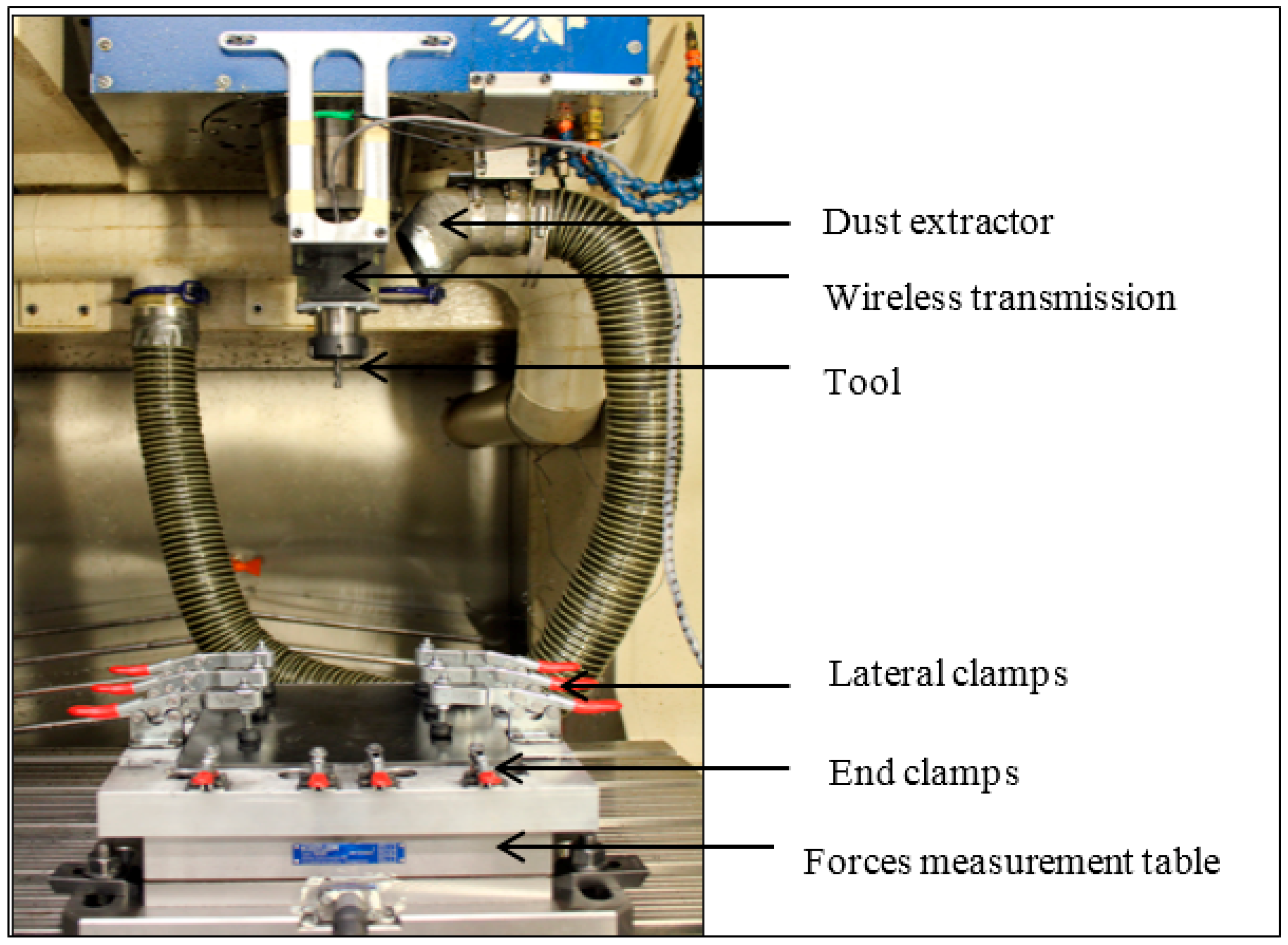
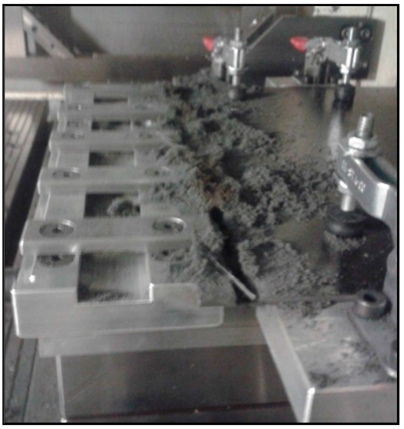
To trim the tensile test coupons, a 3-axis computer numerical control (CNC) HURON K2X10 high-speed machining center and special setup was used (
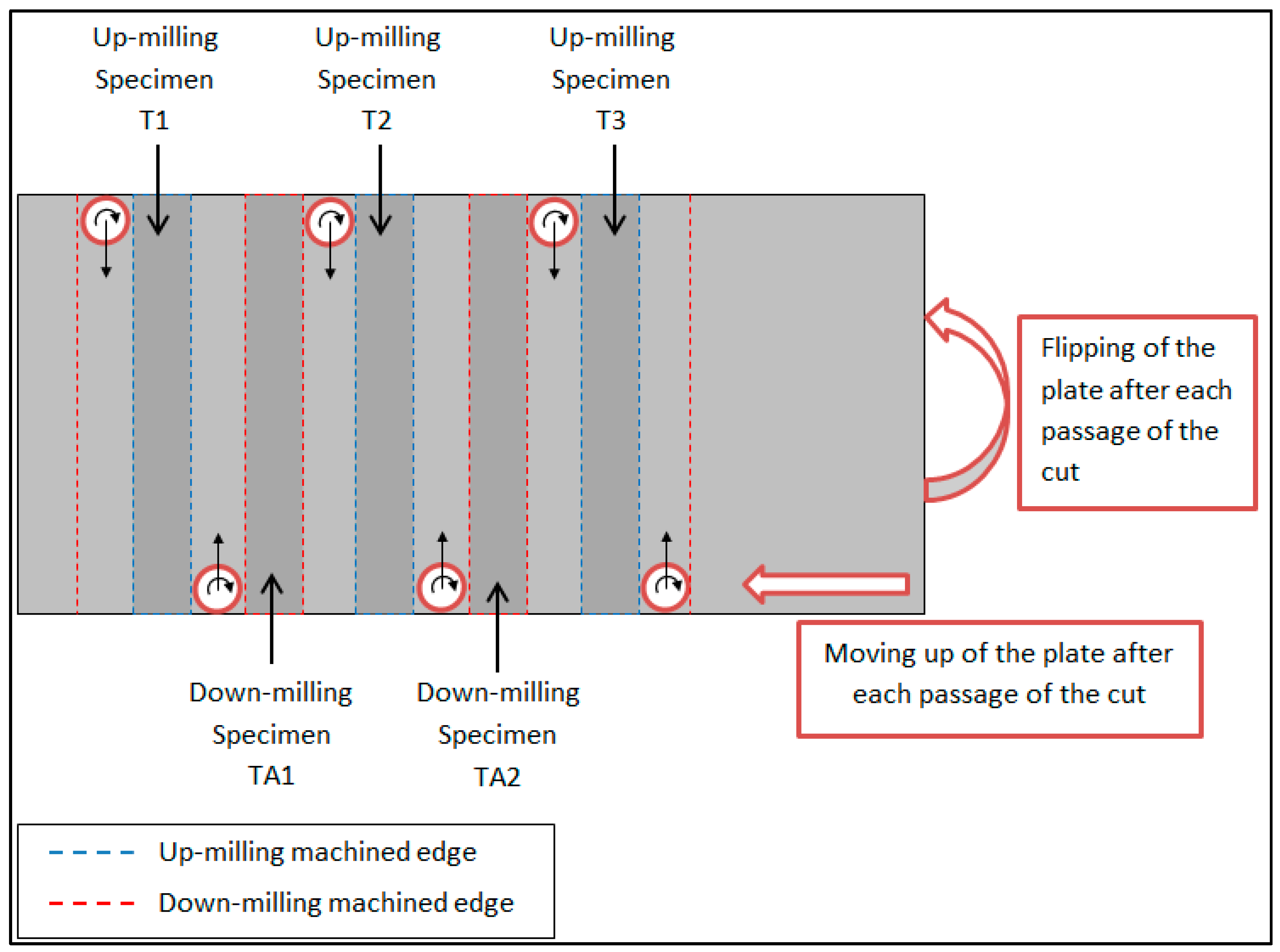
Figure 1). This setup included lateral clamps to maintain the plate during machining, and end clamps to maintain the specimen to be cut. After each pass of the tool, the plate was turned to have a symmetrical temperature profile for each side of the specimen (
Figure 2). Moreover, with this arrangement, the same extra material was obtained for each test specimen. This material corresponded to a specimen with edges machined using the down-milling machining mode rather than the up-milling mode. This meant there were (n − 2) specimens machined in the down-milling mode and n specimens machined in up-milling mode (
Figure 2). All these specimens were kept and compared to one another. Finally, the extremities of the specimens were cut to the desired length of 250 mm (10 ‘) with an abrasive saw. A total of 60 tensile-test specimens were produced as indicated in
Table 1. The specimens were made in four iterations (T1 to T6; T7 to T12; T13 to T22 and T23 to T34). The thermocouples provided the cutting temperature profiles at the cutting edge of the teeth for each sample, except for the following specimens, T3, T11 and T12, where the thermocouples broke through the effect of centrifugal force, and were peeled off due to the flow of chips. Cutting forces were measured using a 3-axis dynamometer table (Kistler 9255B) (
Figure 1).
The specimens were machined in full axial (full-plate thickness) and radial depth of cut to generate the maximum heat during cutting. It was also decided to machine in up-milling configuration because this configuration provides the least mechanical damage. The cutting parameters (
Table 2) were kept constant for all tests and were selected to generate low cutting forces and low tool wear [
20,
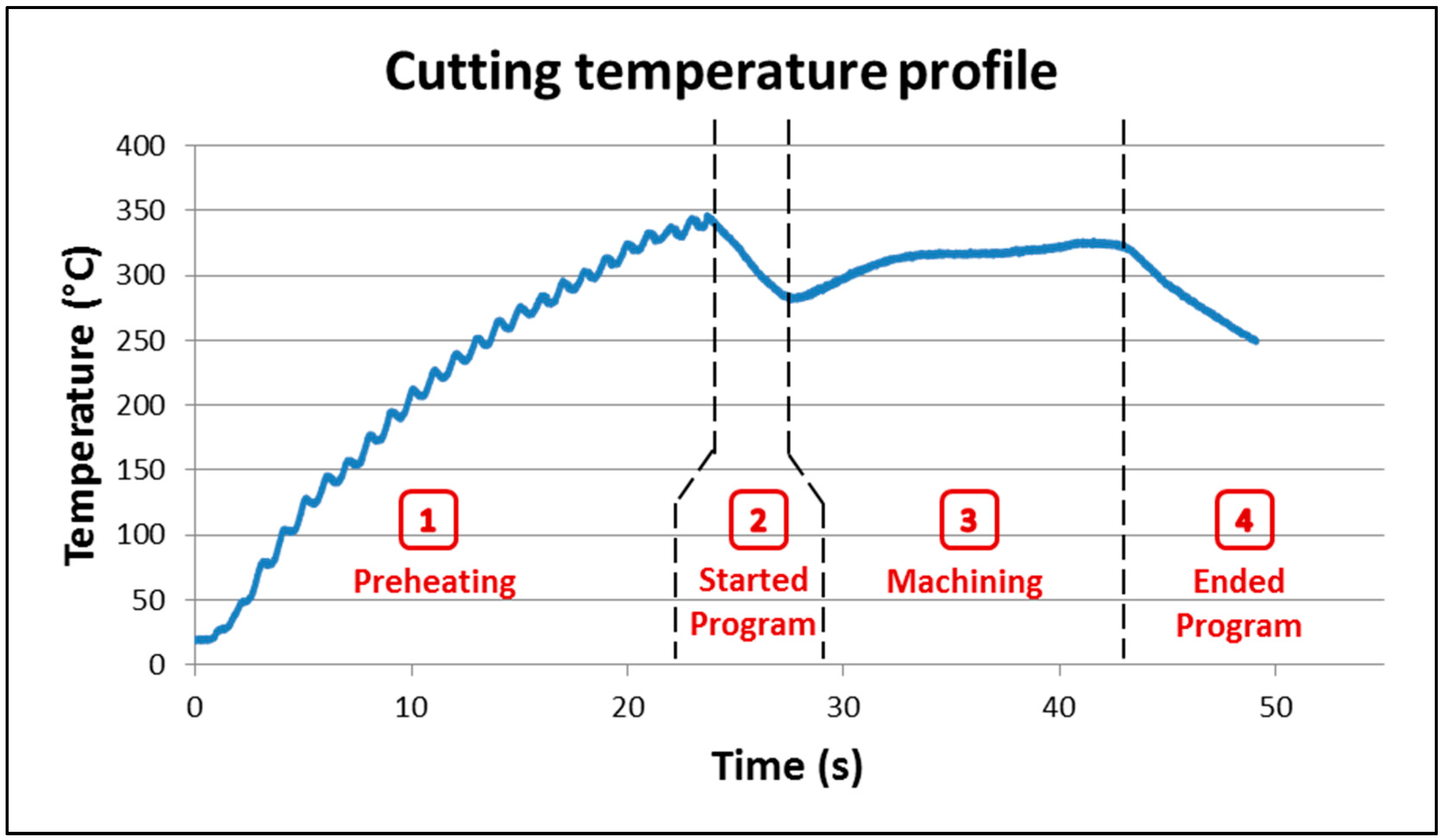
24]. A constant surface temperature was maintained during machining. The cutting temperature reached a constant level after a transient period, of a logarithmic form, occurring when the tool started cutting. This transient period had to be avoided to study the thermal damage at a given temperature along the cutting edge. We wanted the coupon edges for mechanical tests cut with constant temperature as much as possible to reduce variability in the results. For this reason, the tool was pre-heated using a blowtorch to the expected cutting temperature before starting the cutting tests. In fact, preliminary tests confirmed that 300 °C was the appropriate pre-heating temperature for the new tool while 475 °C was appropriate for the worn tool. Once the pre-heat temperature was reached, the machining program was quickly started.
A typical temperature profile was divided into four stages as shown in
Figure 3:
- -
Stage 1: The tool was pre-heated using a blowtorch, the temperature increased up to the required pre-heated temperature.
- -
Stage 2: The CNC doors were closed, the machining program was started, the tool moved from its origin to the part piece. The temperature decreased during this movement.
- -
Stage 3: The tool cut the material. An increase in the temperature up to stabilization was observed.
- -
Stage 4: The machine program ended and the tool came back to its origin. The temperature slowly decreased to ambient temperature.
2.2. Material
The material was a multidirectional quasi-isotropic 24-ply CFRP laminate, shaped into plates of 3.6 mm average thickness. The plates were produced using the manual prepreg lay-up technique, followed by autoclave curing. The stacking sequence of the laminate was [(90°, −45°, 45°, 0°, 45°, −45°, 45°, −45°, 0°, −45°, 45°, 90°)] with a fiber volume fraction of 64%. The high-performance epoxy resin had a curing temperature of 177 °C and a glass-transition temperature of 212 °C.
2.3. Cutting Tool
A six-flute CVD diamond-coated carbide end mill with a diameter of 9.50 mm was used for the trimming experiments. The tool characteristics are shown in
Table 3.
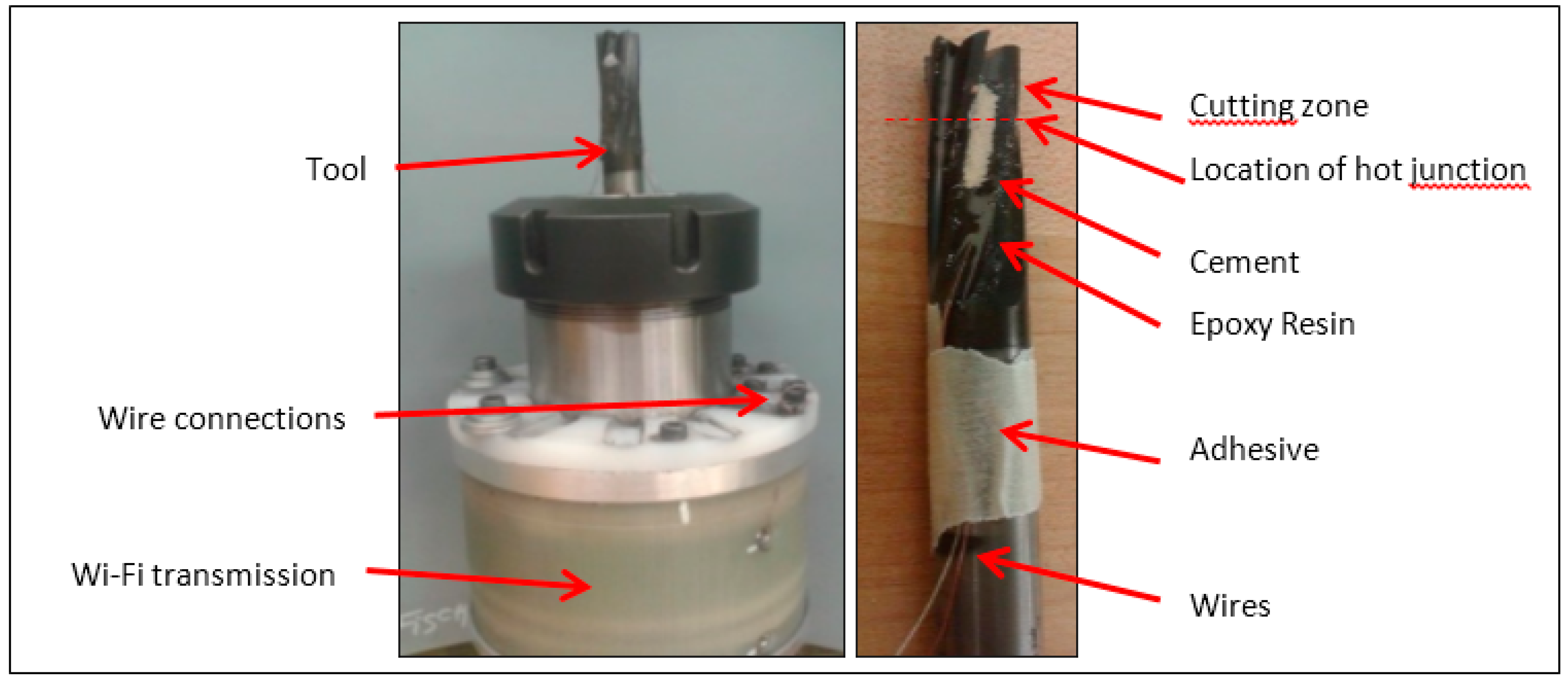
To measure the cutting temperature, the tool was equipped with two embedded K-type thermocouples placed at 180°. They were placed against the cutting edge closest to the cutting area and bonded with OMEGABOND
® 400 # OB-400 cement, which is an excellent thermal conductor and covered with epoxy resin enabling the thermocouple to remain in place during the cutting process. Preliminary tests by Mullier [
24] showed that a distance of 1.7 mm from the cutting edge enables the holding of thermocouple on the tool despite the combined effect of the chip flow and temperature variation (
Figure 4). The tool was then installed in a special mandrel (type M-320, manufactured by Michigan Scientific Corporation), using special connections for thermocouples, and the data was transmitted wirelessly (Wi-Fi) to the data-acquisition system (
Figure 4).
2.4. Tool Wear Measurement
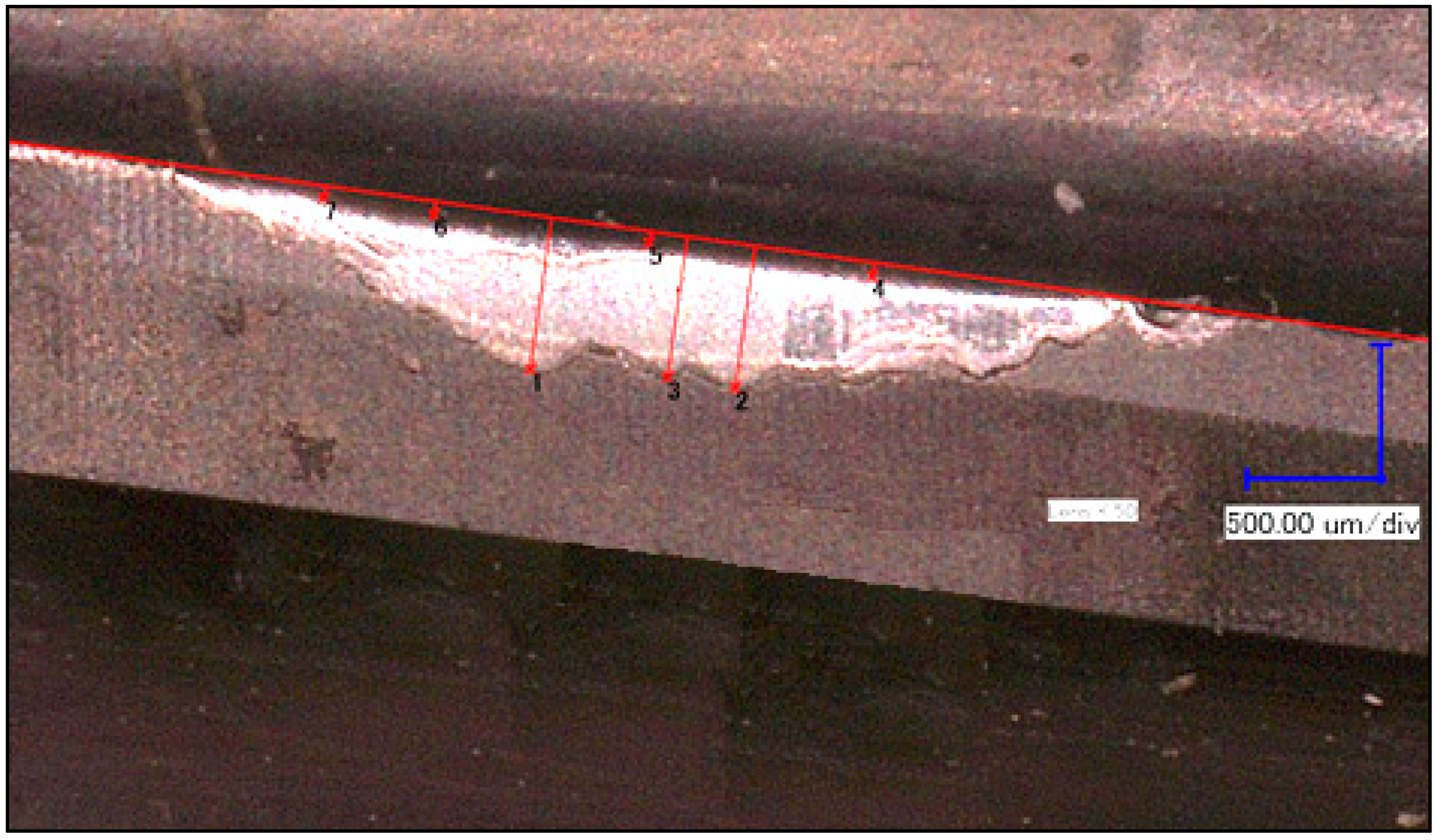
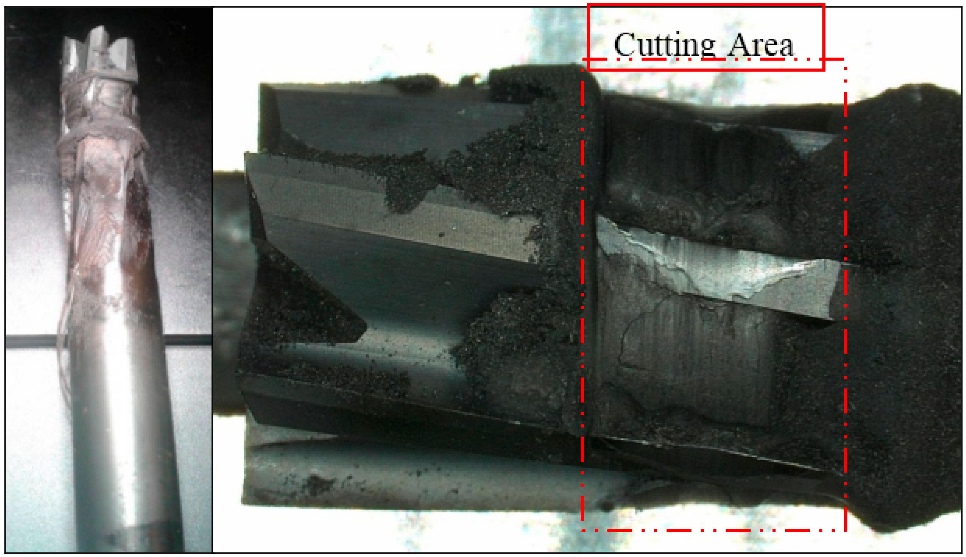
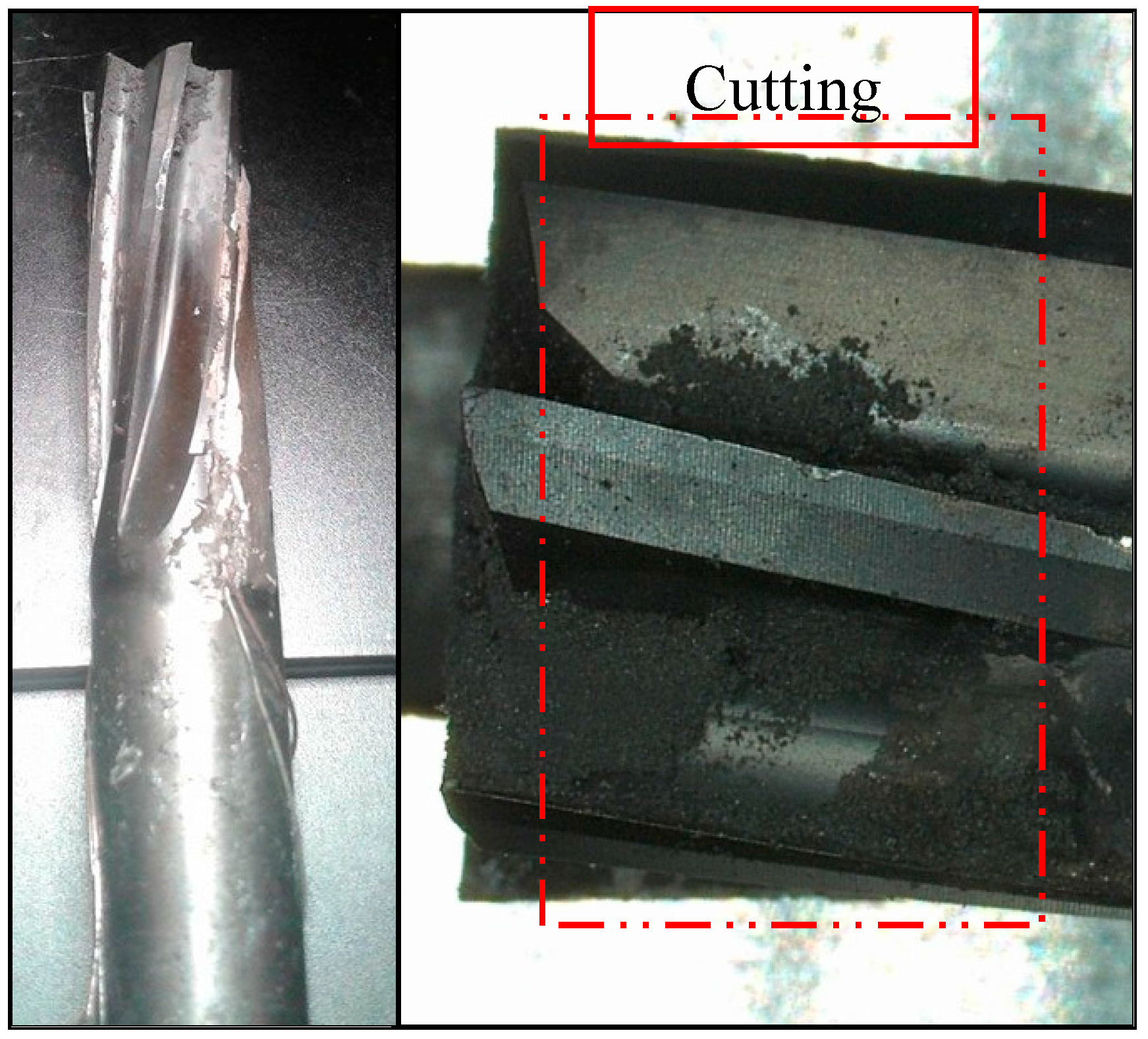
For the trimming operations, a new tool and a worn tool (Vb = 50 μm before machining) were used (
Figure 5). Tool wear has a significant influence on the cutting temperature, thus this approach will show the influence of the cutting temperature on the mechanical properties of the coupons. The tool wear was measured using a Keyence VHX-500FE optical microscope equipped with image-processing software. Regarding the worn tool, the measurement of the initial flank wear (Vb) resulted to 50 µm (wear of the coating and substrate), and we observed a removal of about 550 μm of the diamond coating.
2.5. Surface Roughness Measurement System
The roughness measurement aims to show if the tool wear and the cutting temperature have an influence on the surface roughness. The measurements were made using a Surftest SJ-400 profilometer, from Mituyo, equipped with a 2 µm-radius diamond tip with a 90° angle in combination with SURFPAK-SJ acquisition software. To improve measurement accuracy, a Keyence VHX-500FE optical microscope was used to control the exact position of the profilometer diamond tip.
Following similar studies, the roughness measurements were performed on the plies oriented at −45°. The measurement parameters used are shown in
Table 4 according to the ASME B46.1-2009 standard:
To determine the number of measurements to take on each sample, it is necessary to define the precision of the measuring machine and the operation’s repeatability. For this purpose, three measurements were made on the same specimen and at the same location. Then, 12 measurements were performed on the same sample but at different locations on the edge to determine the repeatability. A deviation of 0.019 µm was found for the precision of the measurement system, and 2.119 µm for the repeatability of the measure. This shows that the measurement process was accurate, but the repeatability of the measure remained limited. This, however, enabled the observation of a trend in the results. To minimize the uncertainty of roughness measurements, it was thus decided to make a large number of measurements. For each test coupon, three random roughness measurements (on the −45° ply) were performed on each machined edge of the coupons. There were two machined edges per coupon which meant six roughness measurements per specimen. A total of 360 measurements were performed (6 × 60 specimens).
2.6. Tensile Testing
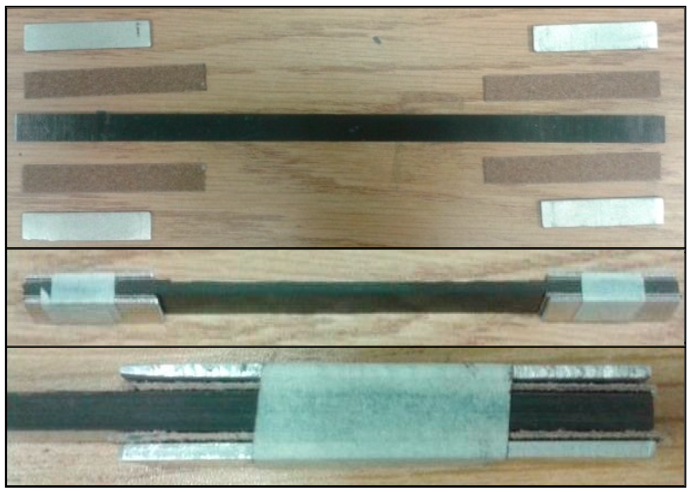
The tensile tests were performed on an Alliance RF/200 testing machine. They were performed according to the ASTM D3039/D3039M-00 standard. The test specimens were clamped in the grips of a length of 50 mm at each end, as recommended by the standard. The use of aluminum tabs bonded at the end of the coupon was adopted to limit the number of coupons breaking in the grips. Aluminum tabs of 12 mm × 50 mm or 6 mm × 50 mm (depending of sample width) were used. To prevent slippage between the specimen and the aluminum tabs, double-face sandpaper with medium grain (100) was placed between the specimen and the tab (
Figure 6).
This test was destructive and only the tensile strength was measured. Therefore, no instrumentation was required on the sample (gauges or extensometer). The confidence intervals related to the test are given in
Table 5. The tensile strength was calculated by dividing the maximum tensile force recorded by the coupon cross-section measured before testing. The cross-section was measured at three locations along the coupon and the mean value was used for calculations.
4. Conclusions
The objective of this study was to study the influence of the cutting temperature caused by a new tool and a worn tool on the ultimate tensile strength. For this, samples of 3.6 × 12 × 250 mm and 3.6 × 6 × 250 mm in carbon/epoxy quasi-isotropic 24-ply laminate composite were machined using a trimming operation. The low specimen width was intended to amplify the influence of thermal damage to the specimen’s edge that was created when cutting. Two cutting configurations were considered: up-milling and down-milling; and two tools were used: a new and a worn to produce different cutting temperatures. The main conclusions are:
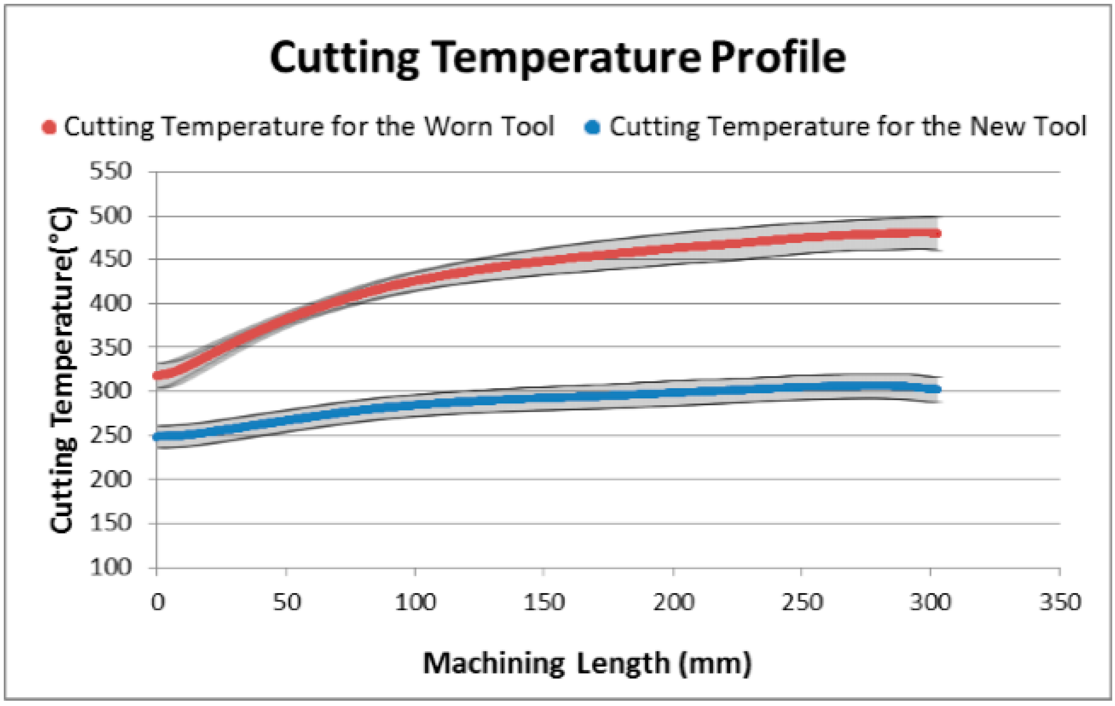
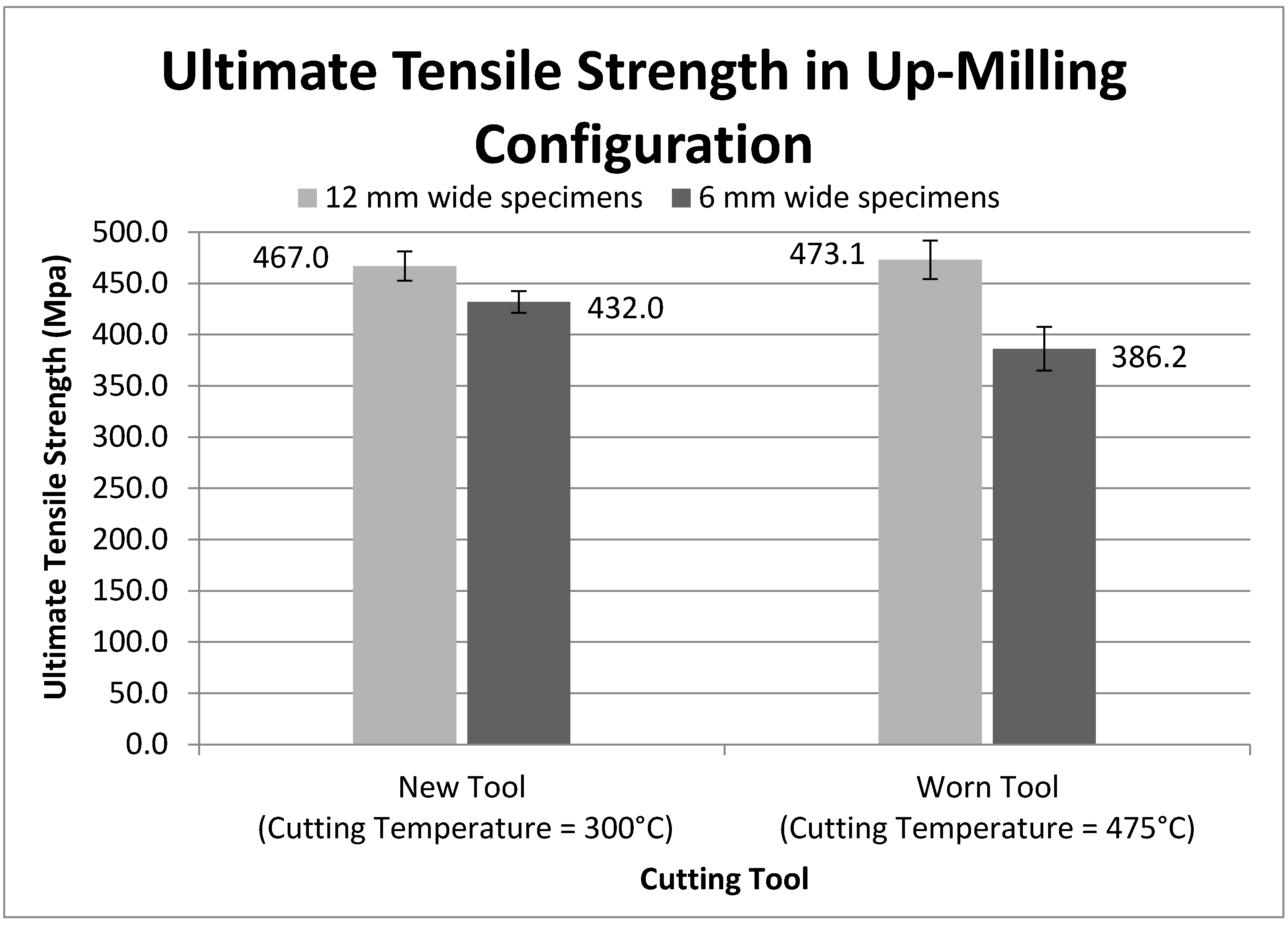
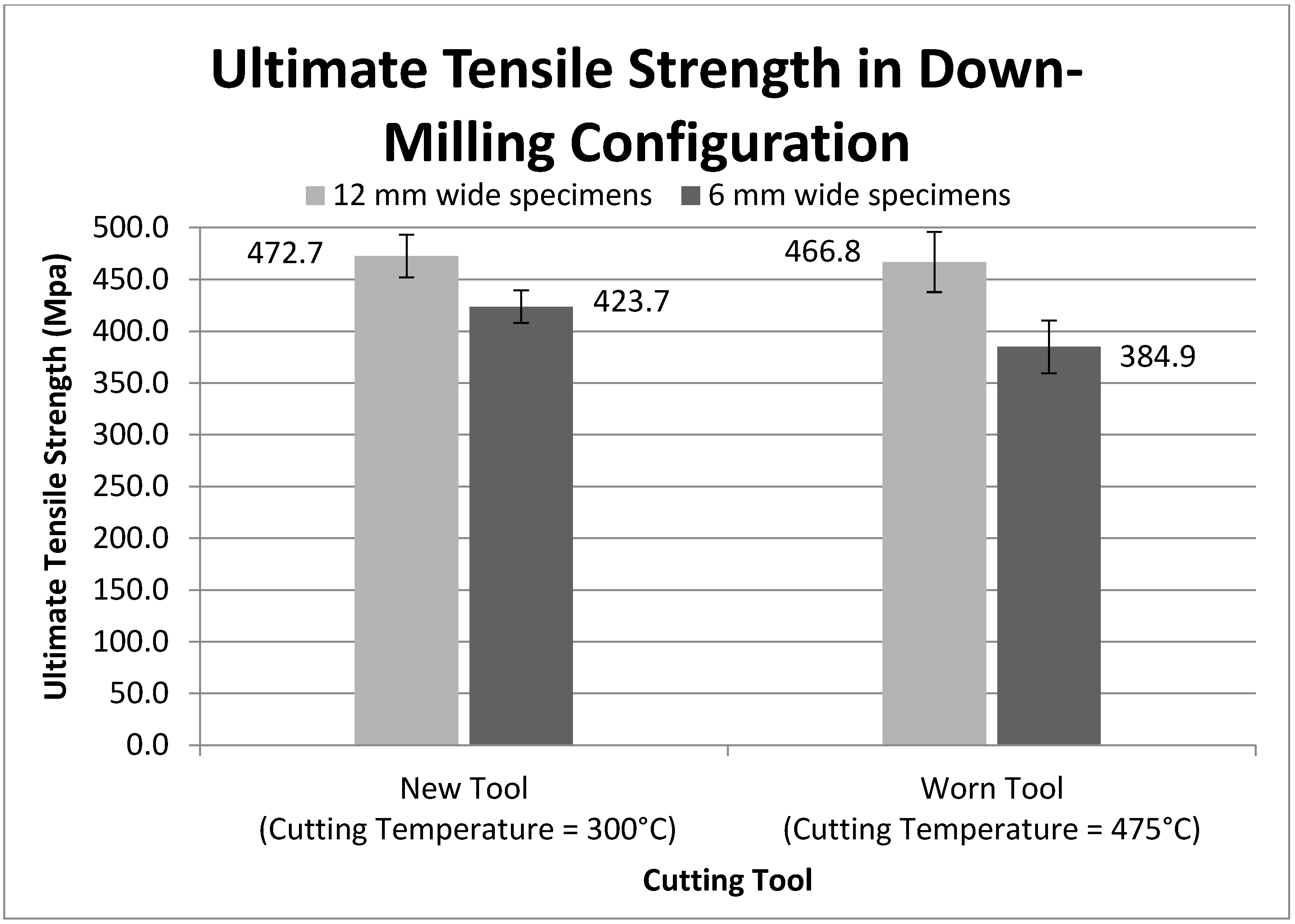
Concerning the cutting-temperature profile, the new tool was pre-heated to 350 °C and an almost constant cutting temperature of 300 °C was reached. The temperature was almost constant throughout the test (step), which was very encouraging. The second tool (worn tool) was pre-heated to 400 °C for a cutting temperature of 475 °C. For each condition, the temperature profiles among the samples were globally the same.
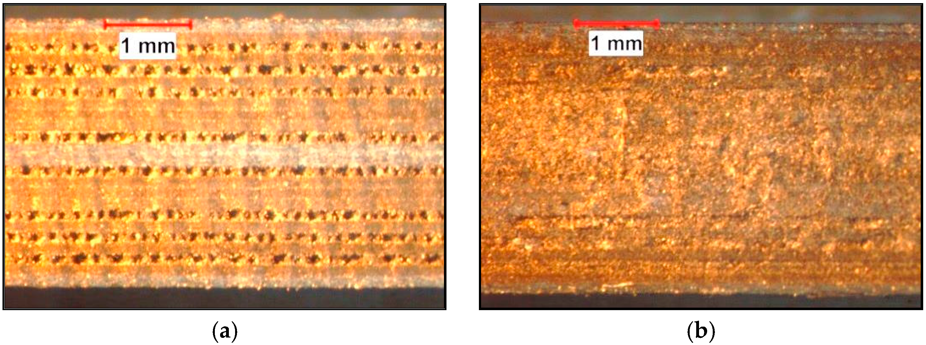
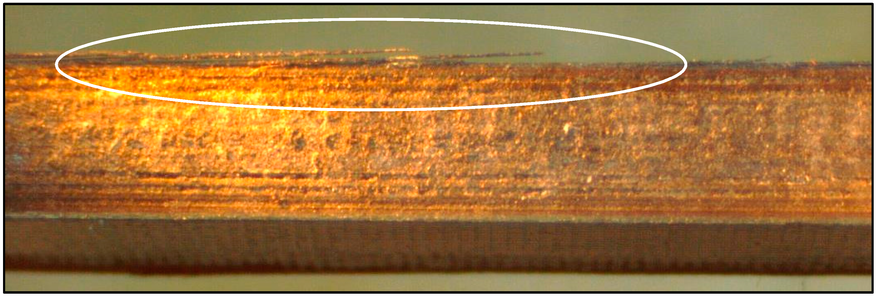
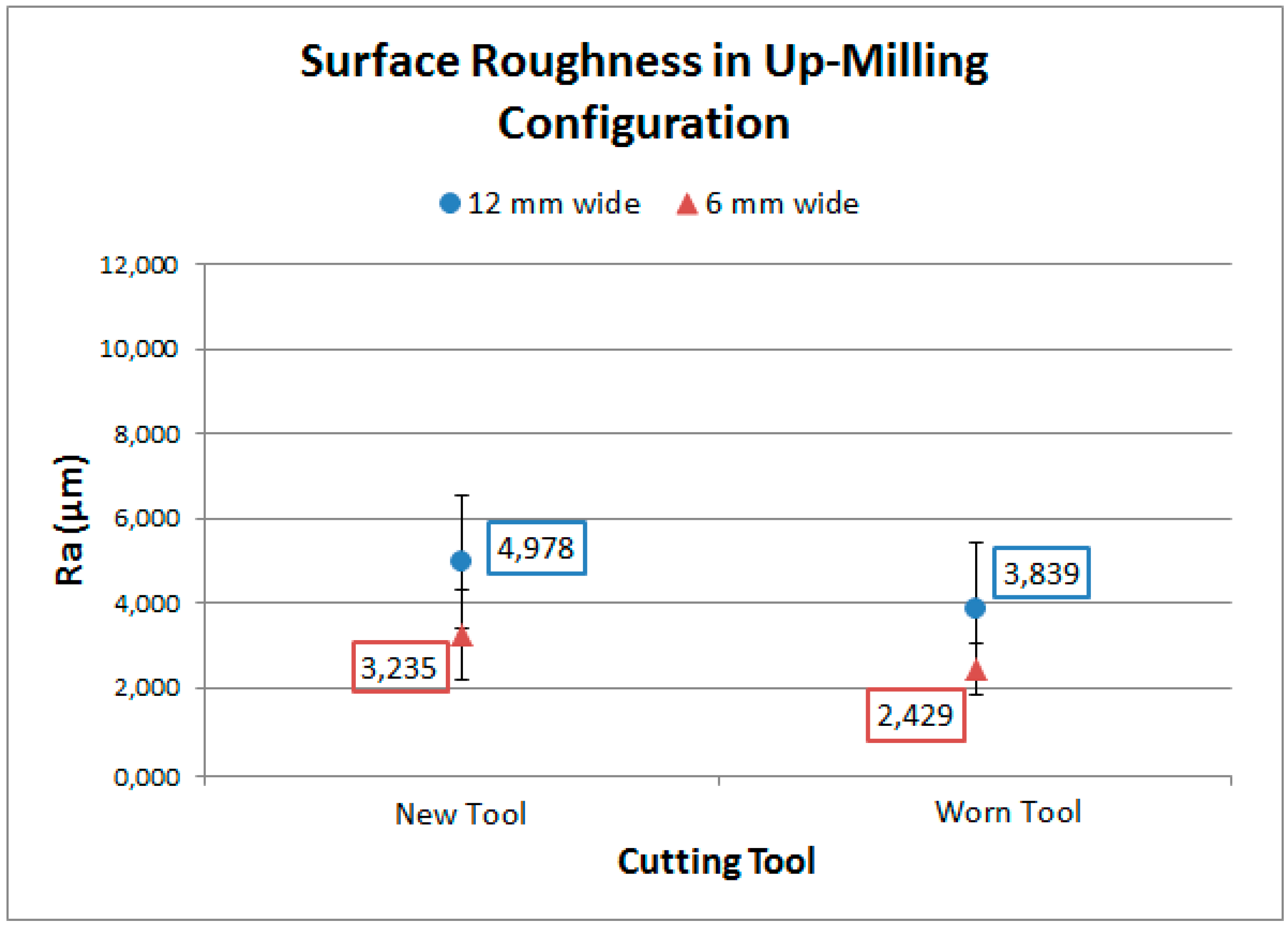
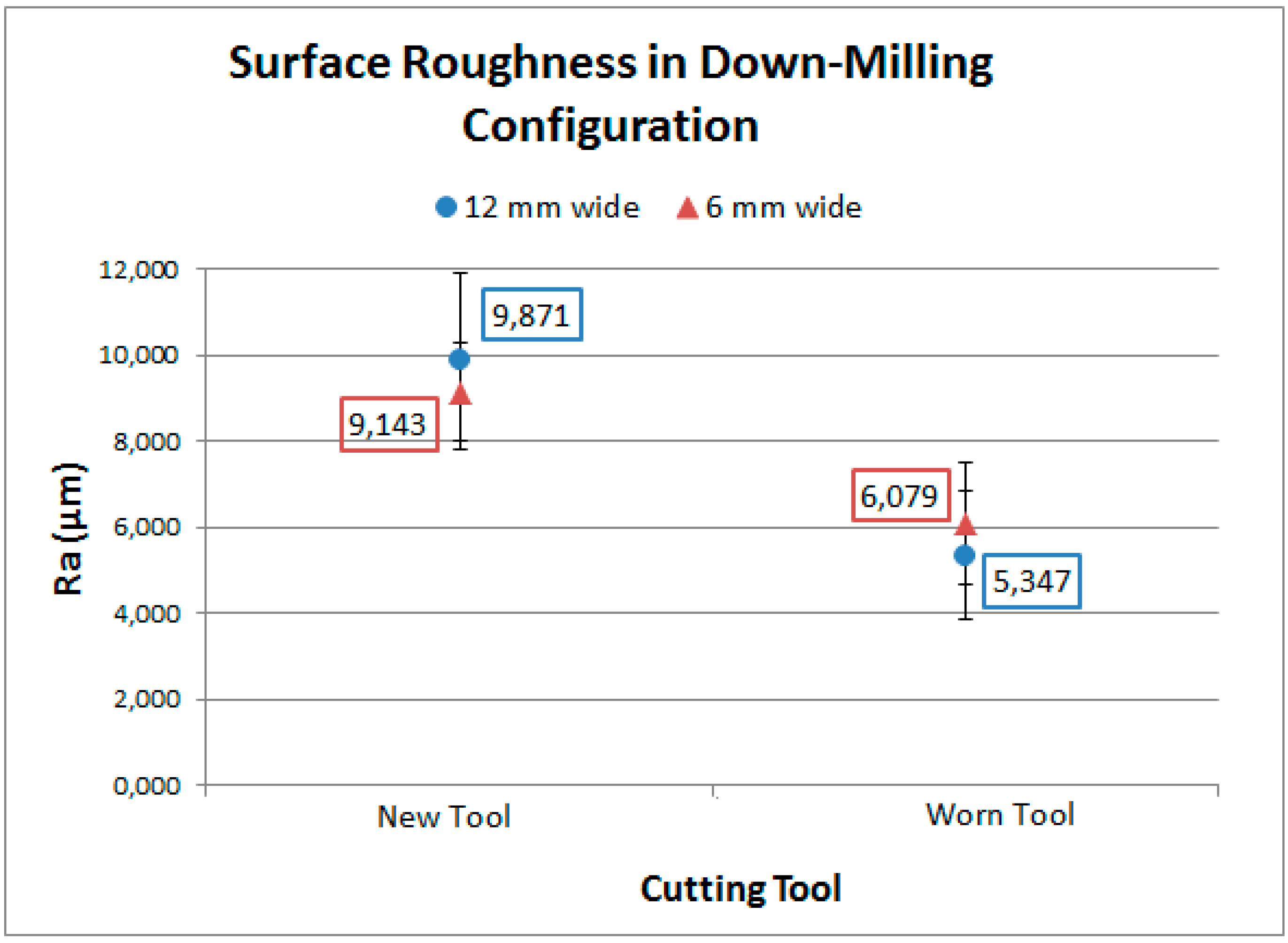
The analysis of the cutting surface with a binocular microscope showed a clear surface and a clear distinction between the plies on the surface machined with a new tool. The most mechanical damage was observed on the plies oriented at −45°. Moreover, the surface did not appear to have been thermally damaged. The most probable explanation was that the majority of the heat generated by cutting was dissipated by the tool and the chip, and was not transmitted to the work piece. For samples machined using the worn tool, a relatively smooth surface was observed, there was no ply distinction. The glass-transition temperature of the resin matrix was definitely reached on the machined surface, resulting in a smooth surface. The matrix was carbonized and the molten resin culminated in a “blur” and smoothing. Uncut fibers or fiber pull-out were also observed for the plies oriented at 0° and −45° for the samples machined with the worn tool in the down-milling configuration.
The roughness measurement showed that the down-milling cutting configuration was not recommended because it produced the worst results and more mechanical damage was noticed. There was also a better roughness for samples machined using the worn tool in both cutting modes.
There was little variation in tensile strength for 12 mm-wide specimens whatever the machining configuration or tool used. A significant decrease of 10% of the tensile strength for the 6 mm-wide test specimens machined by a worn tool was identified compared to those machined with a new tool. It appeared that the edge defects caused by the cutting temperature influenced the mechanical properties at a critical size at which the defect became significant. However, it was difficult to determine whether this decline was due to mechanical or thermal defects. Future development aims to succeed in cooling the tool to room temperature in order to differentiate the mechanical and thermal damage and hence determine which is predominant.
The most relative result of this research regards the performance decrease, which was observed only on small-dimension specimens. This demonstrates that the thermal defects caused during cutting become significant on the mechanical performance of thin parts or thin walls found when holes are located near part edges. This result should be qualified, as the influence of edge defects becomes insignificant as the width of parts or walls exceeds a critical value.


