Article

Multi-Camera Extrinsic Calibration for Real-Time Tracking in Large Outdoor Environments

by
Paolo Tripicchio
1,*,
Salvatore D’Avella
1,
Gerardo Camacho-Gonzalez
1,
Lorenzo Landolfi
2,
Gabriele Baris
1,
Carlo Alberto Avizzano
1 and
Alessandro Filippeschi
1
1
Mechanical Intelligence Institute, Department of Excellence in Robotics & AI, Scuola Superiore Sant’Anna, 56100 Pisa, Italy
2
Istituto Italiano di Tecnologia (IIT), 16163 Genoa, Italy
*
Author to whom correspondence should be addressed.
J. Sens. Actuator Netw. 2022, 11(3), 40; https://doi.org/10.3390/jsan11030040
Submission received: 13 June 2022 / Revised: 22 July 2022 / Accepted: 23 July 2022 / Published: 29 July 2022
(This article belongs to the Section Actuators, Sensors and Devices)

Abstract

:
Calibrating intrinsic and extrinsic camera parameters is a fundamental problem that is a preliminary task for a wide variety of applications, from robotics to computer vision to surveillance and industrial tasks. With the advent of Internet of Things (IoT) technology and edge computing capabilities, the ability to track motion activities in large outdoor areas has become feasible. The proposed work presents a network of IoT camera nodes and a dissertation on two possible approaches for automatically estimating their poses. One approach follows the Structure from Motion (SfM) pipeline, while the other is marker-based. Both methods exploit the correspondence of features detected by cameras on synchronized frames. A preliminary indoor experiment was conducted to assess the performance of the two methods compared to ground truth measurements, employing a commercial tracking system of millimetric precision. Outdoor experiments directly compared the two approaches on a larger setup. The results show that the proposed SfM pipeline more accurately estimates the pose of the cameras. In addition, in the indoor setup, the same methods were used for a tracking application to show a practical use case.

1. Introduction

Vision sensors have been employed in many fields, and are perhaps the most widely adopted kind of sensors. Several manufacturing processes make use of industrial robot arms, and for reaching industrial quality standards in terms of accuracy, precision, and flexibility they regularly exploit vision sensors. Such vision sensors are cameras used to guide a robot in picking and placing [1], performing measurements, or other tasks. There is a need to relate the cameras’ 2D projections with the 3D positions of the robot’s coordinate system in order to accomplish the manufacturing tasks. Therefore, a calibration process is necessary. Other manufacturing processes employ only cameras, for example, to perform quality inspection [2]; in such scenarios, camera calibration is an essential step to identify the defects accurately. The need for camera calibration is more demanding for surveillance in large areas, for example when there is a risk of collision among agents in the scene [3]. In these cases, multiple sensors distributed over a network are needed, along with 3D tracking capabilities of the agents in the area.
A complete calibration procedure computes the camera’s intrinsic and extrinsic parameters and pose with regard to the robot or other cameras. A camera calibration typically determines the camera’s internal geometrical characteristics, i.e., its intrinsic parameters, and the 3D transformation (position and orientation) between the camera’s and the world’s coordinate systems, i.e., the extrinsic parameters, as well as the lenses’ distortion coefficients. Camera calibration can be classified into two categories: photogrammetric calibration and self-calibration. The first [4] relies on an object with a 3D geometry that is precisely known. In the second [5], objects are not known and the camera moves in a static scene, constraining the intrinsic equation. Photogrammetric calibration is more stable and efficient; while self-calibration is more flexible, it is less reliable. When using multiple cameras, it is necessary to relate all of the measurements to a common reference frame, achieving the relative position of all the cameras. Many techniques have been proposed in the literature regarding extrinsic camera calibration. A common approach is based on the use of fiducial markers.
With this approach, special markers are detected in the camera images and their relative poses are estimated by matching markers between multiple cameras. The most common types of markers are ARtag, AprilTag, and CALTag. ARtag markers are binary square markers that have been introduced to apply augmented reality to captured scenes [6]. Their inner binary codification makes them robust for pose detection. AprilTags introduces an increased number of barcodes and reduces false positives and confusion between the tags [7]. ARtag and AprilTag markers, however, have demonstrated high sensitivity to edge occlusion [8]. The CALTag marker has proved to be more robust to overlapping and rotations of the markers thanks to its design and recognition algorithm. Many other fiducial markers are present in the literature, and employ different marker shapes [9].
In the several last years marker-based techniques have seen increasing use, and they are now considered state-of-the-art standards for extrinsic camera calibration. However, considering the research on autonomous vehicles in localization and mapping, valid candidates to achieve more accurate and robust camera calibration can be derived. The motion of a camera can be estimated from Visual Odometry (VO) [10], which can be considered as the estimation process that tries to incrementally obtain a camera pose by measuring the changes in the captured images due to its ego-motion. Therefore the reconstructed trajectory shows only local consistency; when global consistency is necessary, VO algorithms can be used as part of Simultaneous Localization And Mapping (SLAM) procedures [11,12]. Lately, similar methods with single camera inputs have been introduced with the aim of recovering both the relative camera poses and the environment structure. This kind of study is known in the literature under the name of Structure from Motion (SfM) [13]. SfM algorithms are able to reconstruct the relative motion of the camera from unordered sets of images, thus being more general than VO. These algorithms have been widely studied for many years now, and researchers have successfully recovered long-range trajectories from both perspective and omni-directional cameras [14,15,16].
Considering the camera as fixed and the objects in the environments as in motion, such methods can be used to first detect keypoints in the images of different camera views and then match the keypoint features across views in order to obtain 2D–2D point correspondences and solve the camera pose using multi-view geometry.
To the authors’ knowledge, there has been no comparison of these different camera calibration approaches in the literature thus far, specifically when applied to large outdoor environments in which a distributed system of camera nodes is necessary for 3D tracking. Hence, the proposed work presents a novel network of IoT camera nodes and compares the performance of two approaches for automatically estimating their poses in both indoor and outdoor environments. The first approach follows the SfM pipeline, while the other is marker-based. To this end, a network of synchronized camera nodes was designed and implemented. In addition, a fiducial object was designed for the proposed calibration algorithm based on SfM. Figure 1 shows the proposed concept along with the two calibration methods used for comparison. The performance assessment was based on an indoor experiment and an outdoor experiment in a large environment. The indoor experiment was conducted to assess the performance of the two methods with ground truth measurements, employing a commercial tracking system of millimetric precision. Outdoor experiments directly compared the two approaches on a larger setup with uncontrolled illumination. The results show that the proposed SfM pipeline more accurately estimates the pose of the cameras. In addition, the same methods were used for a tracking application in the indoor setup to show a practical use case. The main contributions of this work are as follows:
  • Distributed IoT node architecture for synchronized visual perception of the environment;
  • A comparison of camera calibration algorithms, the former marker-based and the latter based on SfM;
  • A novel and simple calibration tool for the SfM technique.
The remainder of the paper is organized as follows: Section 2 presents related methods in the literature and the problem statement; Section 3 explains the background concepts related to camera calibration (intrinsic and extrinsic); Section 4 provides an overview of the proposed methods; Section 5 shows the experimental setup of the indoor and outdoor scenarios; Section 6 discusses the results obtained from the experiments and the limitations of the proposed approach; and finally, Section 8 concludes the work.

2. State of the Art

Methods for solving the relative camera pose estimation problem can be categorized into geometric methods using the SfM pipeline [17], sometimes called Maker-based [18], and end-to-end deep pose regressors. In the following, both categories of methods are briefly discussed along with the background relative to geometric methods; in particular, state-of-the-art concepts that relate to the Multiple View Geometry field are presented.
Geometric methods estimate the camera pose using a two-stage framework: first, 2D point correspondences among cameras are obtained, then the camera pose is solved by employing a geometric pipeline. Keypoints (Harris [19], FAST [20], etc.) are detected in the images of different views and described with hand-crafted features (SIFT [21], ORB [22], etc.). Such keypoints are matched (BFM [23], FLANN [24], etc.) across images to obtain point correspondences. It is worth noticing that recently many deep learning techniques simultaneously solve the keypoints’ detection and description using neural networks (SuperPoint [25], UR2KiD [26], D2-net [27]). Finally, the poses of the cameras are obtained using a multiview geometry pipeline, which first uses the N-point algorithm [28,29], usually inside a RANSAC [30] loop, to solve for the essential matrix that is then decomposed to the camera rotation and an up-to-scale camera translation [31]. Finally, bundle adjustment [32] is used to further optimize the 3D poses of all cameras. While geometric methods are quite mature, they can present difficulty in feature matching across camera views when the distance between cameras is large. In the presented work, balls attached to the extremities of a wand were used to obtain correspondences for the camera pose estimations.
Deep pose regressors for relative camera pose estimation are quite recent [33,34], and take inspiration from PoseNet [35], which was first applied in absolute camera pose estimation and solved the problem by employing a convolutional neural network [36] trained on data labeled using SfM [37]. It was based on GoogLeNet, with two output branches to regress translations and rotations. Followups of PoseNet include Baysian PoseNet [38], which inputs a pair of images into a Siamese network architecture for extracting deep features from which the camera poses are regressed; Posenet-LSTM [39], where LSTM is used to model the context of the images; and Geometric-PoseNet [40], where the loss is calculated using the re-projection error of the coordinates using the predicted pose and the ground truth. A different approach [41] showed that an end-to-end neural network can be trained to regress to infer the homography between two images. In [42], a regressor network is proposed to produce an essential matrix, which can be then used to find the relative pose. Although an end-to-end process is convenient, the performance of deep regressors has not reached that of geometric methods [43]. In addition, they require images taken from moving cameras for training. In the proposed scenario, the cameras are static, making such approaches inapplicable. A recent work [44] which employs fixed cameras used people in the scene as ‘keypoints’ and associated them across different camera views using re-identification for obtaining correspondences. This method associates human bounding boxes across cameras and converts bounding box correspondences to point correspondences.
Considering the existing literature, Table 1 compares examples of recent research. For each approach, the table reports its underlying method, the features used for matching elements in image pairs, the number of cameras employed in the experiments or that can be supported by the method, whether the method is based on fixed or moving cameras, and whether it is scalable to larger setups. However, none of these approaches considered multiple calibration methods, few in the literature address multiple camera setups, and many are limited to indoor environments. On the contrary, the approach presented in here exploits a custom, low-cost, and easily realizable wand for obtaining correspondences across different camera views that are more robust features for recognition in a scene. Moreover, it compares two different calibration methods, and is shown to be functional and scalable in both indoor and outdoor scenarios.

Problem Statement

The target problem is the estimation of the relative pose of any number of cameras in a common reference frame. The ambition of this work is to solve this problem in large outdoor environments independently of the camera distribution and environmental disturbances.

3. Background on Camera Models

This section introduces the mathematical models underlying standard calibration algorithms, which constitute the background to the proposed methods.

3.1. Intrinsic Calibration with Pinhole Cameras

Everything in the following assumes the use of cameras that follow the pinhole model. Pinhole cameras suffer from distortions introduced by the lenses, and thus require calibration to can determine the relationship between the camera’s natural units (pixels) and the real-world units (meters).
The pinhole model is characterized by a projection matrix, i.e., the camera matrix, and by radial and tangential distortion coefficients. The distortion coefficients do not depend on the scene viewed. On the contrary, the projection matrix changes according to the captured image resolution. Such a matrix is composed of the image’s principal point ( c x , c y ) , which usually is located at the image’s center, and the focal lengths ( f x , f y ) expressed in pixel units.
u v 1 = f x 0 c x 0 f y c y 0 0 1 x u y u 1 = K x u y u 1
The undistorted coordinates ( x u , y u ) are obtained by applying the distortion coefficient to the normalized coordinates ( x n , y n ) , and the normalized coordinates are achieved by dividing the camera-related coordinates by the z coordinate. Finally, the camera-related coordinates are found by transforming the 3D point in the world coordinates with the extrinsic matrix [ R t ] .
x u y u 1 = undistort x n y n 1
x n y n 1 = x / z y / z 1
x y z = R X Y Z + t
This calibration process is usually accomplished using a chessboard or a matrix of circular element patterns captured at different poses: first, the corner of the squares or the centers of the circles composing the chessboard are computed in each view, then an optimization that minimizes the re-projection error in pixel coordinates is used to extract the intrinsic parameters.

3.2. Epipolar Geometry and Essential Matrices

Referring to Figure 2, a 3D point P is projected into two image planes located at different positions, resulting in the projected point image coordinates p = ( x , y , z ) and p 1 = ( x 1 , y 1 , z 1 ) . Using a calibrated camera and undistorted images, normalized coordinates that are independent of the camera model can be used. It is necessary to project back the image points into a unit sphere (for omnidirectional cameras) or into the projection frustum (for perspective cameras) in order to obtain normalized coordinates.
The relationship between the two unknown cameras’ positions to the coordinates of the images is provided by the epipolar constraint:
p 1 T E p = 0 .
Here, E is the essential matrix and can be derived as E = [ T ] x R , where T = [ T x , T y , T z ] = O O 1 is the relative position between the two cameras images, R is the corresponding relative rotation, and [ T ] x is the skew-symmetric matrix, defined as follows:
[ T ] x = 0 T z T y T z 0 T x T y T x 0 .
Therefore, with a set of image correspondences, the epipolar constraint (5) can be used to obtain the relative camera pose.
A different approach to recovering the essential matrix, assuming calibrated cameras and undistorted images, is to use the fundamental matrix [45], as it is more robust for rejecting possible sources of error caused by noisy inputs. Considering the fundamental matrix F 1 2 from camera 1 to camera 2, the corresponding essential matrix E 1 2 is provided by
E 1 2 = K 2 T F 1 2 K 1 ,
where K x is the matrix containing the focal lengths and the principal points of camera x.

3.3. Outliers Removal with RANSAC

In order to obtain a good estimation from the input data, outliers, i.e., feature points with wrong data associations which could corrupt the estimated model, should be removed. The method most widely diffused in the literature to find outliers during model estimation is the Random Sample Consensus (RANSAC) method [30].
In the case of SfM, the model to be estimated is the relative motion between two frames, which can be represented by the motion components R (rotation matrix) and T (translation vector) as estimated from feature correspondences. The RANSAC procedure begins by analyzing minimal sets of data sampled at random, generates model hypotheses from them, then in a second step tests the generated hypotheses on the remaining data elements. Finally, the highest consensus hypothesis which has been obtained is chosen as the best estimation. The number of iterations required to obtain a good solution depends on different factors, such as the number of a minimal set of data points used to formulate a hypothesis, the number of data points, the percentage of outliers in the available data, and the chosen probability of success [30].

3.4. Motion Estimation

After outliers have been removed, Singular Value Decomposition (SVD) is applied to the essential matrix to obtain possible pose hypotheses. The camera pose consists of six degrees-of-freedom (DOF), namely, the rotation (roll, pitch, and yaw) and translation (X, Y, Z) of the camera with respect to the world. Four possible camera pose configurations can be computed: ( C 1 , R 1 ) , ( C 2 , R 2 ) , ( C 3 , R 3 ) , and ( C 4 , R 4 ) , where C R 3 is the camera center and R S O ( 3 ) is the rotation matrix. When applying SVD to a generic matrix A, the decomposition U S V T would be obtained, with U and V orthonormal matrices and a diagonal matrix S that contains the singular values. The four pose configurations can be computed from the essential matrix, being E = U D V T and W = 0 1 0 1 0 0 0 0 0 , as follows:
  • C 1 = U ( : , 3 ) and R 1 = U W V T
  • C 2 = U ( : , 3 ) and R 2 = U W V T
  • C 3 = U ( : , 3 ) and R 3 = U W T V T
  • C 4 = U ( : , 3 ) and R 4 = U W T V T
Such ambiguity should be removed by checking the chirality condition that verifies whether the triangulated 3D points have positive depth [46], i.e., whether the reconstructed points are in front of the cameras.

3.5. Scale Determination

It is not feasible to compute the scale of translation among the camera frames by analyzing the images acquired in sequential poses by cameras. However, it is possible to estimate the relative scales for subsequent transformations. A possible approach is to perform 3D points triangulation from two subsequent image pairs, first obtaining the corresponding 3D points and then measuring the relative distances between them. The scale can be obtained by computing the distance ratio r between a pair of points in P x y z and P x y z , as follows:
r = p i p j p i p j .
The mean of scale ratios obtained from many points should be considered in order to achieve robust results.
Alternatively, a bundle adjustment technique can be used to solve scales between several points using Levenberg–Marquard optimization [47].

4. Methods

This section presents the implementation details of the proposed algorithms. In the first step, each camera is calibrated to obtain the intrinsic parameters and distortion coefficients using checkerboards and the standard algorithm [48]. Two approaches for extrinsic camera calibration are proposed to estimate the orientation and position of each camera in accordance with a chosen world reference frame; one follows the SfM pipeline, while the other is marker-based.

4.1. Marker-Based Camera Pose Estimation

In this approach, a marker is selected from an Aruco dataset [6], printed over a paper sheet, and attached to a rigid plate. An Aruco marker is a binary square fiducial marker formed by a wide black border and an inner binary matrix that determines its identifier. The black border enables its fast detection in the image, and the inner binary codification makes it especially robust, allowing for the possibility of applying error detection and correction techniques. The main benefit of these markers is that a single marker provides enough correspondence, i.e., its four corners, to obtain the camera pose. Aruco markers are divided into dictionaries. The main properties of a dictionary are the dictionary size and the marker size. The first is the number of markers that compose the dictionary, and the former is the size of those markers. Another important dictionary parameter is the inter-marker distance, which represents the minimum distance among its markers and determines the error detection and correction capabilities of the dictionary. In general, smaller dictionary sizes and larger marker sizes increase the inter-marker distance, and vice versa. Therefore, depending on the target environmental space it is important to choose suitable dimensions for the fiducial marker that are adequately visible from all of the cameras. In the proposed work, a square marker of 26.5 cm width was used for the indoor setup, while a square marker of 80 cm width was employed for the outdoor setup. The latter guarantees at least 48 pixels per edge of the marker when its normal is aligned to a camera’s principal axis. OpenCV library functions were used to detect the marker in the image frames. With an image containing ArUco markers, the detection process returns a list of detected markers that includes the position of the four corners in the image and its identifier for each marker. The detection process exploits the binary codification, and should be able to determine the original rotation of the marker in order to correctly number the four corners. Such a detection process first analyzes the image to find square shapes as marker candidates, using adaptive thresholding to segment the markers and extracting the contours from the thresholded image. Wrong markers are filtered out by checking the convexity, the square shape, and the dimensions of the contours. In addition, the final markers are extracted from candidate markers by analyzing their inner codification. Therefore, a perspective transformation can be applied to obtain the marker in its canonical form, and the canonical image is thresholded using the Otsu algorithm to separate white and black bits. Then, the number of black or white pixels in each cell is counted to determine whether it is a white or a black bit, and the bits are analyzed to determine whether the marker belongs to the specific dictionary.
In order to obtain the camera pose from the information provided by the ArUco marker detection (the four corners), the Perspective-n-Point problem needs to be solved. The projection formula is provided by
u v w = K R t X Y Z W
where R = [ r 1 r 2 r 3 ] is the rotation matrix representing the orientation of the camera and t is the translation. With the ArUco markers, the four points lie on a plane. Therefore, transformation from the world to the image plane becomes a homograph; to know the pose of the camera with respect to the tag knowing that the tag is on a plane, the world coordinate has the coordinate Z = 0 . Therefore, the projection Formula (9) becomes
u v w = K R t X Y W
where R = [ r 1 r 2 ] . The objective is to find the homography H = [ R t ] that encompasses the pose of the camera, where the two unknowns are R and t. Being K 1 H = [ h 1 h 2 h 3 ] , the rotation matrix R can be computed as [ h 1 h 2 h 1 × h 2 ] , and the translation t can be computed as t = h 3 | | h 1 | | .
The obtained transformation T i m represents the pose estimation of marker m in the frame of camera i. By computing such transformations for all the cameras, it is possible to relate the poses of the cameras to the marker itself. In particular, assuming that a marker m is visible in both cameras, the homogeneous transformation matrix T from camera i to camera j is provided by
T i j = T i m ( T j m ) 1 .
A similar procedure is repeated for several different marker positions inside the environment under analysis in order to verify the correct reconstruction of the poses of the cameras.

4.2. SFM-Based Camera Pose Estimation

An SfM algorithm is composed of the following steps:
  • Feature extraction
  • Feature matching/tracking
  • Outlier removal
  • Motion/Pose estimation
  • Bundle adjustments
Each step of the proposed SfM method is discussed below in detail.

4.2.1. Feature Extraction

The proposed approach exploits a custom wand for the calibration procedure allowing complete control over the selection of feature points. Even for this method, it is important to select the size of the wand in accordance with the target environmental scenario in order to guarantee fair vision for all the cameras. The wand was realized by placing two colored balls (green and orange, with a 6 cm radius in the indoor setup and a 12.5 cm radius in the outdoor setup) at the extremities of two staffs 100 cm long and 140 cm long, respectively. A software package was responsible for finding the balls and estimating their centers. The detection of the balls occurred on the basis of their colors, which were selected in order to be relatively easy to identify in the outdoor scenario. In particular, the detection algorithm worked as follows: the camera image was converted in Hue Saturation Value (HSV) color space in such a way that the light changes typical of outdoor imaging did not affect the balls’ color descriptions. Then, masks in the specific color range for the selected green and orange colors were employed to filter the image and find the circular blobs, and the largest blob with a radius considered to be feasible was selected as the correct candidate. Finally, the center of the chosen blob was computed from principal image moments M * * as follows:
x , y = M 10 M 00 , M 01 M 00

4.2.2. Feature Matching

The wand confers an advantage in the feature matching phase, as for every wand position in the 3D environment the position in the image space of the two balls at its extremities is computed for each camera and compared among the cameras directly. Whenever a misdetection occurs, it is discarded by the subsequent estimation steps.

4.2.3. Pose Estimation

As already discussed, the estimation of the cameras’ poses can be obtained by computing the relative transformations among the cameras and defining a common frame of reference. The proposed approach computes the fundamental matrix for each pair of cameras using the RANSAC algorithm, which allows for discarding the wrong feature matches and offers the possibility of choosing a desired maximum reprojection error for the estimation. The latter aspect can play a crucial role, as the images can be noisy, the quality of the camera optics may not be high, and approximation of the pinhole could introduce possible errors during the projection calculations. Then, the essential matrix is computed from the fundamental matrix and the relative camera pose candidates are generated via SVD decomposition. As mentioned above, while four solutions exist, only one, i.e., the one that allows points to be reprojected in front of both cameras, is correct. In our implementation, feature points in the 3D space were obtained via triangulation, and the solution that projected all of the points in a positive depth space (z-coordinate of the first camera reference frame) was selected as the correct one. At this point, the transformation is correct up to a scale factor. The proposed implementation can rely on the fact that the distance between the features belongs to a wand 88 cm long in the indoor setup and 115 cm long in the outdoor setup. Therefore, the scale factor can be computed by dividing the exact measurement m 0 by the mean, median, or mode of all the computed distances of the detected features. These three statistical measures are usually not very different from each other in practice. However, it could be possible that the distribution of the computed distances is not Gaussian due to external noise. By computing a histogram of the obtained distances, as shown in Figure 3, a peak is found at a certain value, suggesting that the mode could better approximate the correct measure. As an example, Figure 3 shows two parts of this pipeline: the reconstruction of reprojected wand trajectories and the selectable metrics for estimation of the wand length in the distance histogram.

4.2.4. Bundle Adjustments

After computing the relative transformations between two consecutive images and concatenating the transformation to recover a complete trajectory of the camera, it is possible to perform an iterative refinement considering both the previous pose and the last n poses to increase the accuracy of the local trajectory estimation. Such an approach is called windowed bundle adjustment (BA) [32]. In addition, the selection of good keyframes is important for reducing the drift during 3D triangulation, which is necessary for estimating the re-projection error. Windowed BA reduces the drift compared to 2-view VO, as it incorporates constraints between several frames. In addition, loop detection algorithms [49] can largely improve the estimation of the motion. It is worth noting that in the proposed method it is not the camera that moves around; rather, it is the wand that moves in front of the camera. The underlying mathematical problem is the same, and a solution can be found by triangulating the wand extremities between two cameras or using BA to optimize both the reprojected points and the cameras’ positions by considering all the cameras together.

4.3. IoT Camera Nodes

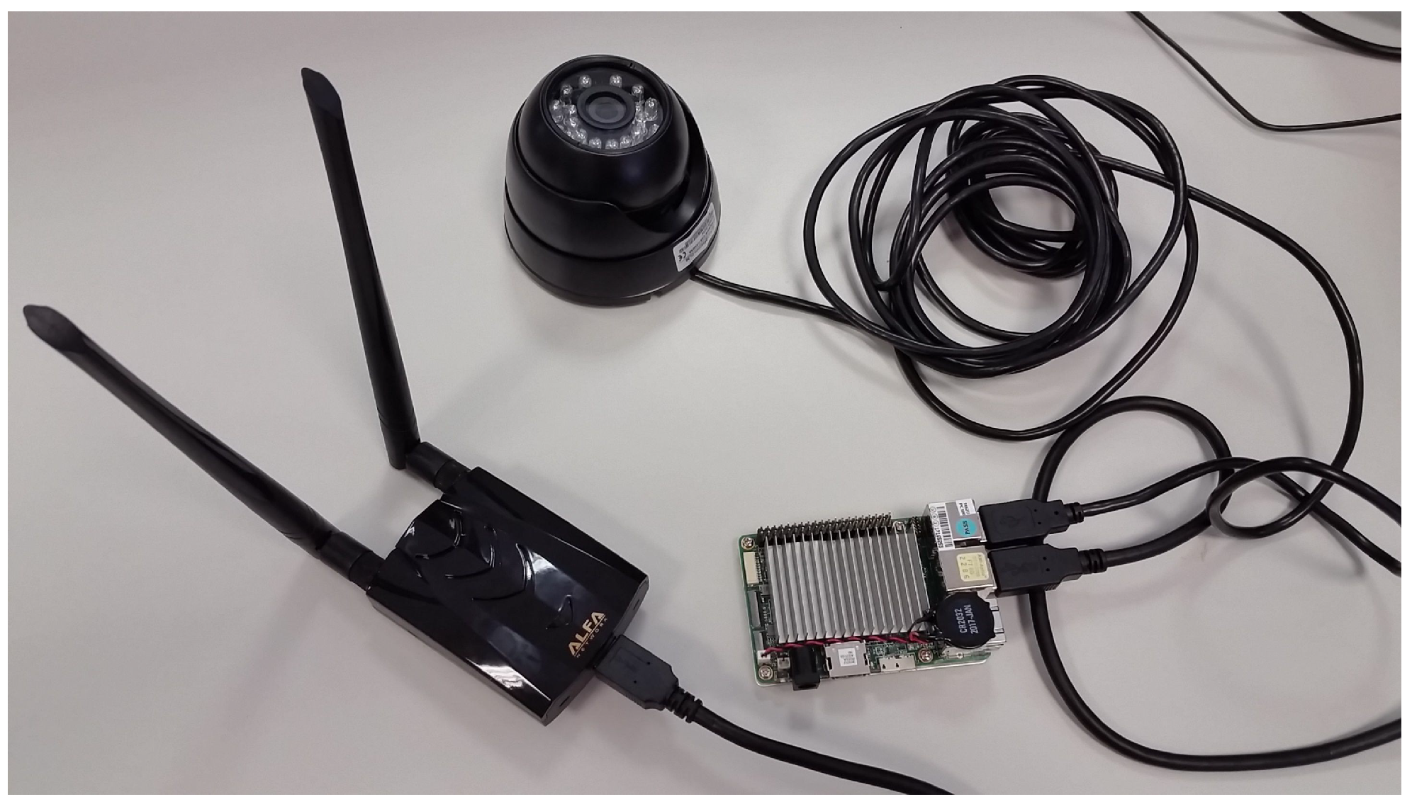
The hardware infrastructure relies on a distributed network of IoT camera nodes, four in the indoor setup and five in the outdoor setup. A node consists of a USB camera and its edge computing device. Such nodes communicate through a wireless network. In particular, we used off-the-shelf low-cost hardware; detailed information is reported in Table 2. Figure 4 shows an example of the type of IoT camera node used in the experiments.
The cost per node was bounded by low-cost cameras equipped with low-quality optical lenses suffering from high distortion, making the calibration more difficult. The cost could be reduced even further by substituting the up-board and router with cheaper devices (e.g., a Raspberry Pi or a lower-end NETGEAR model, respectively). Potentially, the cost could be reduced to less than USD 50 per node. In the presented scenario, the cost of the whole system, excluding the master node, was approximately USD 300. Both the master node and the up-boards ran the Linux operating system. Note that the results reported in Section 6 are only affected by the quality of the cameras, and the choice of the remaining hardware is agnostic to the calibration procedure.

4.3.1. Software System

A software package was developed to control the distributed network of nodes from the master node. Communication among the nodes was based on web sockets [50], a protocol that allows for two-way communication among the nodes of a network through HTTP. The code executed by the master node was written in NodeJS [51], while the code executed by the computing nodes was written in python, exploiting the python-socketio library. In addition, a minimal web interface was developed to start the calibration procedure and gather images in the master node as well as to receive visual feedback on the quality of the captured images and the field of view of the cameras. Finally, the NodeJS architecture allowed for fast recovery of the WebSockets connection between the nodes and the master in case of a failure of the master.

4.3.2. Synchronization Algorithm

A protocol for synchronizing the frames among the cameras was developed in order to guarantee that feature matching would happen among the same frames across cameras. This protocol was made of the following steps:
  • The user sets a number N of images requested to be taken by each camera;
  • A TAKE(i) message is broadcast from the master to the nodes, triggering the acquisition of a frame;
  • An acknowledgment message (ACK) is sent by each node to the master after the acquisition;
  • The master waits for the ACK message to be received from each node, then it broadcasts a TAKE(i+1) message;
  • Steps 2 to 4 are repeated until N desired number of acquisitions are reached.
Figure 5 shows a possible execution of the synchronization protocol described above using four camera nodes.

5. Testing Environments and Setups

This section details the experimental setups in the indoor and outdoor scenarios.

5.1. Indoor Setup

In the indoor setup, four cameras were attached to four columns over a reticular structure at a height of about two meters, pointing down towards the center of the floor enclosed by the structure. The longer side of the rectangle was 7.4 m long, while the shorter side measured 3.7 m. Figure 6 shows an example of the synchronized images acquired from this setup.

5.2. Outdoor Setup

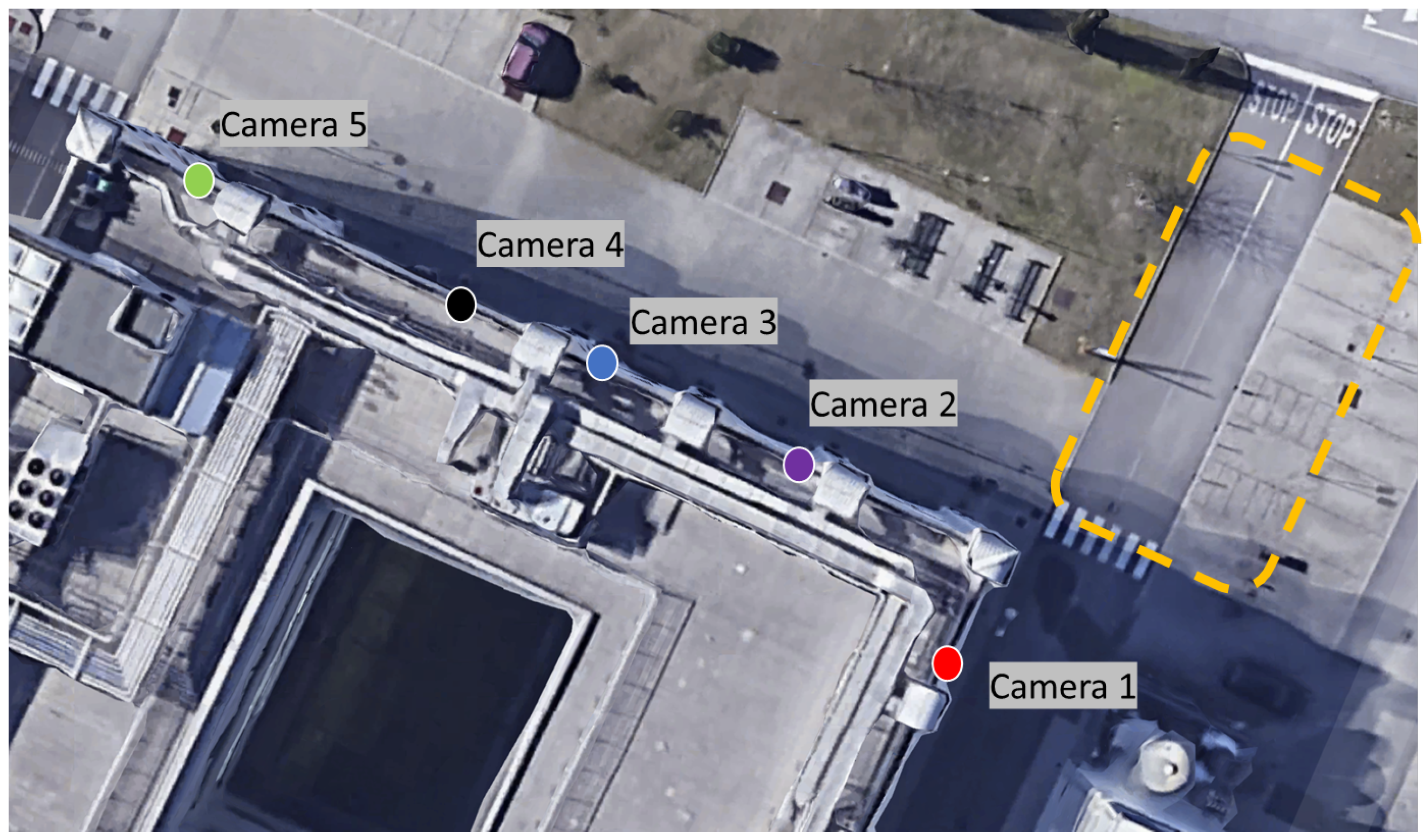
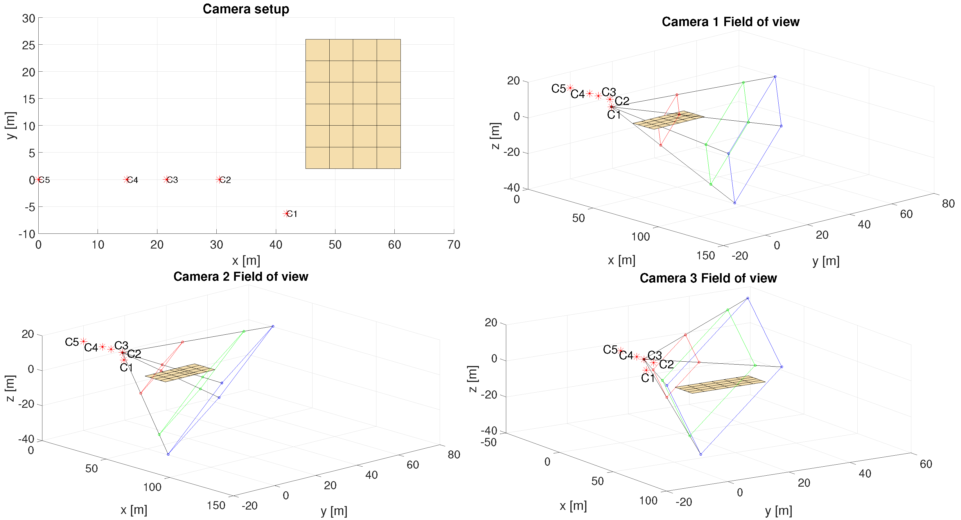
The outdoor setup involved five cameras placed over the roof of a tall building (nearly 11 m high) and pointing down to the area close to the building entrance. Figure 7 shows the theoretical geometric setup. This setup was chosen to stress the capability of the proposed approach in coping with a strict field of view and collinear camera setups, which usually cause issues in the calibration step. Figure 8 depicts examples of frames captured by the cameras during the calibration steps involving both the Aruco Marker and the wand. As mentioned before, for the outdoor scenario the radius of the wand spheres and the size of the marker were increased in order to improve the visibility of the features, considering the greater distance from the cameras. In particular, the Aruco markers were printed on a rigid carton plate with a side of 800 mm, and the wand length was increased to 140 cm with a ball diameter of 25 cm. Low-cost (up to 10 $ each) camera lenses were selected to guarantee sufficient coverage of the area and a minimum density of 60 ppm in the covered area. Figure 9 shows the frustum and pixel density for each camera in the outdoor setup.

6. Results

In this section, we report the results of the experiments carried out to assess the performance of the proposed calibration methods.

6.1. Ground Truth

For the preliminary study in the indoor setup, a ground truth trajectory in a three-dimensional metric space using a VICON (https://www.vicon.com/software/nexus/, accessed on 12 June 2022) system was generated. The VICON was installed on the same reticular structure where the cameras are placed, avoiding any occlusions. An Aruco marker was placed on a wooden table, over which a set of VICON sensors having a known topology were attached. The center of this topology coincided with the center of the marker. The marker was tracked along the trajectory by both the VICON tracking system and the proposed marker-based method. It was decided to stop the tracked object in n predefined positions in order to avoid synchronization issues, as the capture frequency of VICON is much higher than the frequency of the cameras. In each position, the VICON measurement was sampled to obtain a set of ground truth measurements G = { g i R 3 : i [ 1 , n ] } ; the positions of the same set of points were then estimated by exploiting the marker-based calibration and the SfM, achieving A = { a i R 3 : i [ 1 , n ] } and S = { s i R 3 : i [ 1 , n ] } , respectively.

6.2. Indoor Setup

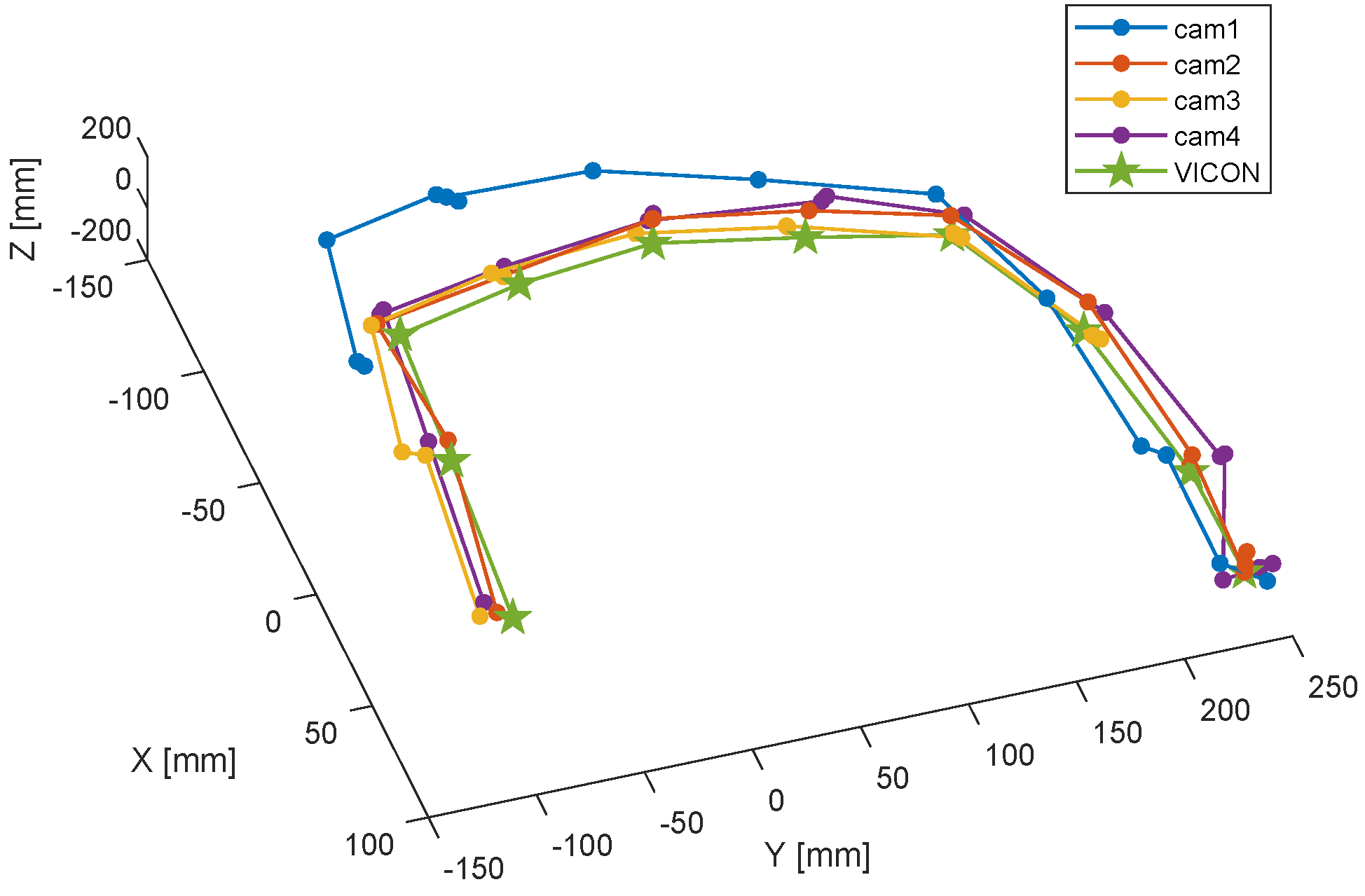
In this section, the comparison between a trajectory reconstructed through the cameras and the VICON system is discussed. The ground truth trajectory is depicted in Figure 10 along with the sampled points acquired by the system of cameras. Each black point in the figure represents the ground truth position of the center of the marker for a t and s t estimations, where t is the time index. Figure 11 shows the reconstruction of the marker trajectory by assuming to know the transformation between the Aruco reference frame and VICON for the first detected point.

6.3. Outdoor Setup

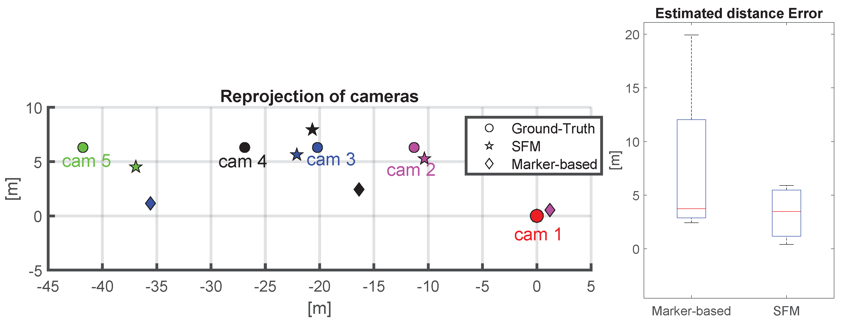
To estimate the cameras’ poses in the outdoor scenario, a capture of 500 frames each was acquired. The synchronized images depicting the wand motion in a small portion of the outdoor environment that was visible from all the cameras’ view frustums were then used to compute a pose estimation through the SfM approach. On the contrary, only a single captured frame for each camera was necessary for marker-based estimation. Additionally, the marker was moved on a tridimensional trajectory within the outdoor environment to capture the motion trajectory. This trajectory was used to verify the capability of the marker-based approach to reconstructing coherent tracking motions from multiple cameras. The results depicted in Figure 12 show that the SfM approach provides a better estimation concerning the camera poses in the environment. Wrong pose estimations could depend on the different camera lenses used (see Table 3), which probably did not correctly fit on the pinhole model, and certainly on depend on the resolution and clarity of the marker image as perceived from a long distance. In the SfM case, this computational error is mitigated by triangulation and optimization being carried out on several frames. However, referring to Figure 13, even if the estimation of the marker-based approach is not accurate, the resulting tracking motion captured from different cameras has a bounded reconstruction error; thus, considering the knowledge of the environment under surveillance, the error in the height estimation can be reduced using a projection on the plane of motion.

7. Discussion

The indoor setup experiment showed that the proposed SfM method is feasible and achieves very good reconstruction performance. In fact, the average position error in the comparison against the VICON system is about 5 mm. The main results of the experiments are related to the camera pose estimation in outdoor conditions, and show that the SfM method achieves better performance than the marker-based method. The challenging conditions of the experiment stressed the weaknesses of both methods. These conditions included camera alignment, illumination, and poor quality of the cameras and the lenses. The camera alignment made it difficult for both methods to perform triangulation, especially for cameras farther from the target volume. Reflexes due to illumination and background colors had detrimental effects on the recognition of the fiducial object in the SfM pipeline. Under these conditions, the limitations of the marker-based method, mainly due to its need for recognition of several corners and relatively stronger need for high resolution, caused very high errors in the reconstruction of the camera poses. The SfM method performed better, even if it resulted in errors on the order of 1 to 5 m. The proposed fiducial object proved to be more suitable than markers to address the needs of a larger setup without requiring additional cameras. This makes the proposed method much more scalable for large areas than marker-based alternatives. In addition to camera pose estimation, the trajectory tracking performance shows the coherence of the reconstruction among cameras for both the SfM and the marker-based approaches, which finally provides evidence of the usability of these methods for 3D trajectory tracking in outdoor environments.

Limitations

This work was limited to testing five cameras, although no theoretical limitations are present as each camera was provided with its own computation node. However, possible limitations may arise due to the required bandwidth in the whole communication system. A second possible limitation is due to environmental conditions potentially affecting either the communication channel or the image acquisition process.

8. Conclusions

Vision sensing is a mature technology, and its use in large outdoor scenarios is envisaged in both the industrial and social worlds. In particular, in many application scenarios there is the need to track and analyze the motion or behavior of human personnel and machines in order to guarantee people’s safety and restrict access control. In this context, the present manuscript introduced a network of camera nodes and compared two alternative methods that enable multi-camera calibration and tracking in large outdoor environments. The experimental setup employed low-cost cameras inside IoT nodes; the results show that even with cost-effective optics and sensors, an extrinsic calibration can be achieved allowing for proper tracking of objects. The method employing SfM algorithms proved to be more accurate in camera pose reconstruction compared to the classical marker-based approach. These results demonstrate that in changing lighting conditions typical of outdoor environments, and with low-resolution features from a few pixels to sub-pixel point correspondence, the proposed approach enables object and people tracking in large outdoor setups.

Author Contributions

Conceptualization, P.T. and A.F.; investigation, P.T., S.D., G.C.-G., L.L., G.B. and A.F.; methodology, P.T., S.D., L.L. and A.F.; project administration, A.F.; resources, C.A.A. and A.F.; software, P.T., S.D., G.C.-G., L.L. and A.F.; supervision, P.T. and A.F.; validation, P.T., S.D., L.L. and A.F.; writing—original draft, P.T. and L.L.; writing—review and editing, P.T., S.D., C.A.A. and A.F. All authors have read and agreed to the published version of the manuscript.

Funding

This research was funded by INAIL (National Institute for Insurance against Accidents) grant number BRIC2016-ID24.

Institutional Review Board Statement

Not applicable.

Informed Consent Statement

Not applicable.

Data Availability Statement

Not applicable.

Conflicts of Interest

The authors declare no conflict of interest.

References

  1. D’Avella, S.; Tripicchio, P.; Avizzano, C.A. A study on picking objects in cluttered environments: Exploiting depth features for a custom low-cost universal jamming gripper. Robot. Comput.-Integr. Manuf. 2020, 63, 101888. [Google Scholar] [CrossRef]
  2. Tripicchio, P.; Camacho-Gonzalez, G.; D’Avella, S. Welding defect detection: Coping with artifacts in the production line. Int. J. Adv. Manuf. Technol. 2020, 111, 1659–1669. [Google Scholar] [CrossRef]
  3. Filippeschi, A.; Pellicci, M.; Vanni, F.; Forte, G.; Bassani, G.; Landolfi, L.; De Merich, D.; Campo, G.; Avizzano, C.A.; Bergamasco, M. The Sailport Project: A Trilateral Approach to the Improvement of Workers’ Safety and Health in Ports. In Advances in Safety Management and Human Factors, Proceedings of the International Conference on Applied Human Factors and Ergonomics, Washington, DC, USA, 24–28 July 2019; Springer: Berlin/Heidelberg, Germany, 2019; pp. 69–80. [Google Scholar]
  4. Zhang, Z. Flexible camera calibration by viewing a plane from unknown orientations. In Proceedings of the Seventh IEEE International Conference on Computer Vision, Kerkyra, Greece, 20–27 September 1999; Volume 1, pp. 666–673. [Google Scholar]
  5. Luong, Q.T.; Faugeras, O.D. Self-calibration of a moving camera from point correspondences and fundamental matrices. Int. J. Comput. Vis. 1997, 22, 261–289. [Google Scholar] [CrossRef]
  6. Garrido-Jurado, S.; Muñoz Salinas, R.; Madrid-Cuevas, F.; Marín-Jiménez, M. Automatic Generation and Detection of Highly Reliable Fiducial Markers Under Occlusion. Pattern Recognit. 2014, 47, 2280–2292. [Google Scholar] [CrossRef]
  7. Olson, E. AprilTag: A robust and flexible visual fiducial system. In Proceedings of the 2011 IEEE International Conference on Robotics and Automation, Shanghai, China, 9–13 May 2011; pp. 3400–3407. [Google Scholar]
  8. Sagitov, A.; Shabalina, K.; Sabirova, L.; Li, H.; Magid, E. ARTag, AprilTag and CALTag Fiducial Marker Systems: Comparison in a Presence of Partial Marker Occlusion and Rotation. In Proceedings of the 14th International Conference on Informatics in Control, Automation and Robotics (ICINCO), Madrid, Spain, 26–28 July 2017; pp. 182–191. [Google Scholar] [CrossRef]
  9. Daftry, S.; Maurer, M.; Wendel, A.; Bischof, H. Flexible and User-Centric Camera Calibration using Planar Fiducial Markers. In Proceedings of the British Machine Vision Conference, Bristol, UK, 9–13 September 2013. [Google Scholar]
  10. Scaramuzza, D.; Fraundorfer, F. Visual odometry [tutorial]. IEEE Robot. Autom. Mag. 2011, 18, 80–92. [Google Scholar] [CrossRef]
  11. Yousif, K.; Bab-Hadiashar, A.; Hoseinnezhad, R. An Overview to Visual Odometry and Visual SLAM: Applications to Mobile Robotics. Intell. Ind. Syst. 2015, 1, 289–311. [Google Scholar] [CrossRef]
  12. Tripicchio, P.; Unetti, M.; Giordani, N.; Avizzano, C.A.; Satler, M. A lightweight slam algorithm for indoor autonomous navigation. In Proceedings of the Australasian Conference on Robotics and Automation (ACRA 2014), Melbourne, Australia, 2–4 December 2014. [Google Scholar]
  13. Hartley, R.I.; Zisserman, A. Multiple View Geometry in Computer Vision, 2nd ed.; Cambridge University Press: Cambridge, UK, 2004; ISBN 0521540518. [Google Scholar]
  14. Konolige, K.; Agrawal, M.; Solà, J. Large-Scale Visual Odometry for Rough Terrain. In Robotics Research: The 13th International Symposium ISRR; Kaneko, M., Nakamura, Y., Eds.; Springer: Berlin/Heidelberg, Germany, 2011; pp. 201–212. [Google Scholar] [CrossRef] [Green Version]
  15. Corke, P.; Strelow, D.; Singh, S. Omnidirectional visual odometry for a planetary rover. In Proceedings of the 2004 IEEE/RSJ International Conference on Intelligent Robots and Systems (IROS) (IEEE Cat. No.04CH37566), Sendai, Japan, 28 September–2 October 2004; Volume 4, pp. 4007–4012. [Google Scholar] [CrossRef] [Green Version]
  16. Forster, C.; Pizzoli, M.; Scaramuzza, D. SVO: Fast semi-direct monocular visual odometry. In Proceedings of the 2014 IEEE International Conference on Robotics and Automation (ICRA), Hong Kong, China, 31 May–7 June 2014; pp. 15–22. [Google Scholar]
  17. Yi, G.; Jianxin, L.; Hangping, Q.; Bo, W. Survey of structure from motion. In Proceedings of the 2014 International Conference on Cloud Computing and Internet of Things, Changchun, China, 13–14 December 2014; pp. 72–76. [Google Scholar] [CrossRef]
  18. Korthals, T.; Wolf, D.; Rudolph, D.; Hesse, M.; Rückert, U. Fiducial Marker based Extrinsic Camera Calibration for a Robot Benchmarking Platform. In Proceedings of the 2019 European Conference on Mobile Robots (ECMR), Prague, Czech Republic, 4–6 September 2019; pp. 1–6. [Google Scholar] [CrossRef]
  19. Harris, C.; Stephens, M. A combined corner and edge detector. In Proceedings of the Alvey Vision Conference, Manchester, UK, 31 August–2 September 1988; Volume 15, pp. 10–5244. [Google Scholar]
  20. Rosten, E.; Drummond, T. Machine learning for high-speed corner detection. In Proceedings of the European Conference on Computer Vision; Springer: Berlin/Heidelberg, Germany, 2006; pp. 430–443. [Google Scholar]
  21. Lowe, D.G. Distinctive image features from scale-invariant keypoints. Int. J. Comput. Vis. 2004, 60, 91–110. [Google Scholar] [CrossRef]
  22. Rublee, E.; Rabaud, V.; Konolige, K.; Bradski, G. ORB: An efficient alternative to SIFT or SURF. In Proceedings of the 2011 International Conference on Computer Vision, Barcelona, Spain, 6–13 November 2011; pp. 2564–2571. [Google Scholar]
  23. Jakubović, A.; Velagić, J. Image feature matching and object detection using brute-force matchers. In Proceedings of the 2018 International Symposium ELMAR, Zadar, Croatia, 16–19 September 2018; pp. 83–86. [Google Scholar]
  24. Muja, M.; Lowe, D. Flann-Fast Library for Approximate Nearest Neighbors User Manual; Computer Science Department, University of British Columbia: Vancouver, BC, Canada, 2009; Volume 5. [Google Scholar]
  25. DeTone, D.; Malisiewicz, T.; Rabinovich, A. Superpoint: Self-supervised interest point detection and description. In Proceedings of the IEEE Conference on Computer Vision and Pattern Recognition Workshops, Salt Lake City, UT, USA, 18–22 June 2018; pp. 224–236. [Google Scholar]
  26. Yang, T.Y.; Nguyen, D.K.; Heijnen, H.; Balntas, V. Ur2kid: Unifying retrieval, keypoint detection, and keypoint description without local correspondence supervision. arXiv 2020, arXiv:2001.07252. [Google Scholar]
  27. Dusmanu, M.; Rocco, I.; Pajdla, T.; Pollefeys, M.; Sivic, J.; Torii, A.; Sattler, T. D2-net: A trainable cnn for joint description and detection of local features. In Proceedings of the IEEE/CVF Conference on Computer Vision and Pattern Recognition, Long Beach, CA, USA, 15–20 June 2019; pp. 8092–8101. [Google Scholar]
  28. Li, H.; Hartley, R. Five-point motion estimation made easy. In Proceedings of the 18th International Conference on Pattern Recognition (ICPR’06), Hong Kong, China, 20–24 August 2006; Volume 1, pp. 630–633. [Google Scholar]
  29. Nistér, D. An efficient solution to the five-point relative pose problem. IEEE Trans. Pattern Anal. Mach. Intell. 2004, 26, 756–770. [Google Scholar] [CrossRef] [PubMed]
  30. Fischler, M.A.; Bolles, R.C. Random Sample Consensus: A Paradigm for Model Fitting with Applications to Image Analysis and Automated Cartography. Commun. ACM 1981, 24, 381–395. [Google Scholar] [CrossRef]
  31. Georgiev, G.H.; Radulov, V. A practical method for decomposition of the essential matrix. Appl. Math. Sci. 2014, 8, 8755–8770. [Google Scholar] [CrossRef]
  32. Triggs, B.; McLauchlan, P.F.; Hartley, R.I.; Fitzgibbon, A.W. Bundle adjustment—A modern synthesis. In Proceedings of the International Workshop on Vision Algorithms, Corfu, Greece, 21–22 September 1999; pp. 298–372. [Google Scholar]
  33. Balntas, V.; Li, S.; Prisacariu, V. Relocnet: Continuous metric learning relocalisation using neural nets. In Proceedings of the European Conference on Computer Vision (ECCV), Munich, Germany, 8–14 September 2018; pp. 751–767. [Google Scholar]
  34. Ding, M.; Wang, Z.; Sun, J.; Shi, J.; Luo, P. CamNet: Coarse-to-fine retrieval for camera re-localization. In Proceedings of the IEEE/CVF International Conference on Computer Vision, Seoul, Korea, 27 October–2 November 2019; pp. 2871–2880. [Google Scholar]
  35. Kendall, A.; Grimes, M.; Cipolla, R. Posenet: A convolutional network for real-time 6-dof camera relocalization. In Proceedings of the IEEE International Conference on Computer Vision, Santiago, Chile, 11–18 December 2015; pp. 2938–2946. [Google Scholar]
  36. Gu, J.; Wang, Z.; Kuen, J.; Ma, L.; Shahroudy, A.; Shuai, B.; Liu, T.; Wang, X.; Wang, G.; Cai, J.; et al. Recent advances in convolutional neural networks. Pattern Recognit. 2018, 77, 354–377. [Google Scholar] [CrossRef] [Green Version]
  37. Ullman, S. The interpretation of structure from motion. Proc. R. Soc. Lond. Ser. B Biol. Sci. 1979, 203, 405–426. [Google Scholar]
  38. Melekhov, I.; Ylioinas, J.; Kannala, J.; Rahtu, E. Relative camera pose estimation using convolutional neural networks. In Proceedings of the International Conference on Advanced Concepts for Intelligent Vision Systems, Auckland, New Zealand, 10–14 February 2017; pp. 675–687. [Google Scholar]
  39. Walch, F.; Hazirbas, C.; Leal-Taixe, L.; Sattler, T.; Hilsenbeck, S.; Cremers, D. Image-based localization using lstms for structured feature correlation. In Proceedings of the IEEE International Conference on Computer Vision, Venice, Italy, 22–29 October 2017; pp. 627–637. [Google Scholar]
  40. Kendall, A.; Cipolla, R. Geometric loss functions for camera pose regression with deep learning. In Proceedings of the IEEE Conference on Computer Vision and Pattern Recognition, Honolulu, HI, USA, 21–26 July 2017; pp. 5974–5983. [Google Scholar]
  41. Rocco, I.; Arandjelovic, R.; Sivic, J. Convolutional neural network architecture for geometric matching. In Proceedings of the IEEE Conference on Computer Vision and Pattern Recognition, Honolulu, HI, USA, 21–26 July 2017; pp. 6148–6157. [Google Scholar]
  42. Yi, K.M.; Trulls, E.; Ono, Y.; Lepetit, V.; Salzmann, M.; Fua, P. Learning to find good correspondences. In Proceedings of the IEEE Conference on Computer Vision and Pattern Recognition, Salt Lake City, UT, USA, 18–22 June 2018; pp. 2666–2674. [Google Scholar]
  43. Shavit, Y.; Ferens, R. Introduction to camera pose estimation with deep learning. arXiv 2019, arXiv:1907.05272. [Google Scholar]
  44. Xu, Y.; Li, Y.J.; Weng, X.; Kitani, K. Wide-Baseline Multi-Camera Calibration using Person Re-Identification. In Proceedings of the IEEE/CVF Conference on Computer Vision and Pattern Recognition, Nashville, TN, USA, 20–25 June 2021; pp. 13134–13143. [Google Scholar]
  45. Luong, Q.T.; Faugeras, O.D. The fundamental matrix: Theory, algorithms, and stability analysis. Int. J. Comput. Vis. 1996, 17, 43–75. [Google Scholar] [CrossRef]
  46. Nister, D. An efficient solution to the five-point relative pose problem. In Proceedings of the Computer Vision and Pattern Recognition, Madison, WI, USA, 16–22 June 2003; Volume 2, pp. 195–202. [Google Scholar] [CrossRef]
  47. Lourakis, M.L.A.; Argyros, A.A. Is Levenberg-Marquardt the most efficient optimization algorithm for implementing bundle adjustment? In Proceedings of the Tenth IEEE International Conference on Computer Vision (ICCV’05), Beijing, China, 17–21 October 2005; Volume 2, pp. 1526–1531. [Google Scholar] [CrossRef] [Green Version]
  48. Tsai, R. A versatile camera calibration technique for high-accuracy 3D machine vision metrology using off-the-shelf TV cameras and lenses. IEEE J. Robot. Autom. 1987, 3, 323–344. [Google Scholar] [CrossRef] [Green Version]
  49. Bazeille, S.; Filliat, D. Combining Odometry and Visual Loop-Closure Detection for Consistent Topo-Metrical Mapping. RAIRO—Oper. Res. 2011, 44, 365–377. [Google Scholar] [CrossRef] [Green Version]
  50. Fette, I.; Melnikov, A. The WebSocket Protocol. RFC 6455, RFC Editor. 2011. Available online: http://www.rfc-editor.org/rfc/rfc6455.txt (accessed on 12 June 2022).
  51. Dahl, R. Node. js: Evented I/O for v8 Javascript. Available online: https://www.nodejs.org (accessed on 12 June 2022).
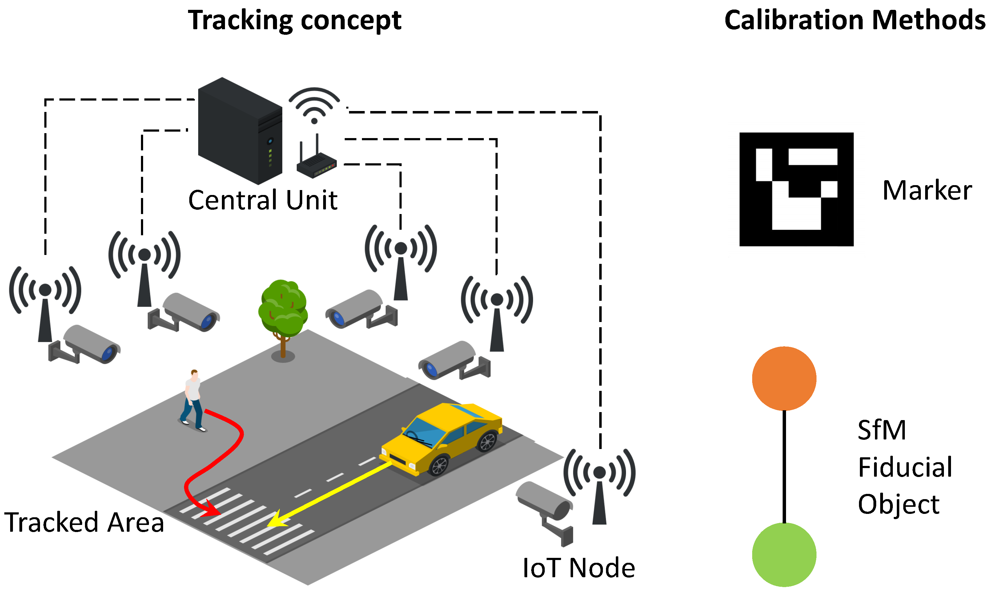
Figure 1. Schematic representation of the IoT node architecture along with an outdoor target area and two tracked agents.
Jsan 11 00040 g001
Figure 2. Schematic representation of a 3D point P as seen from two different camera positions, that is, alternatively as the p projection or the p 1 projection. The points e and e 1 are the epipoles of the two recorded images, l and l 1 are the respective epipolar lines, and the triangle = O P O 1 ^ represents the epipolar plane.
Jsan 11 00040 g002
Figure 3. (Left): Example of a trajectory performed by the wand for two-camera calibration as reprojected by a pair of cameras. (Right): Histogram of computed distances between wand features, with marked statistical measures obtained from the sequence of wand movements. The green dot indicates the mode, the magenta dot is the median, the cyan dot indicates the result of LM optimization, and the red dot indicates the mean of the distribution.
Jsan 11 00040 g003
Figure 4. Hardware of a single capture node.
Jsan 11 00040 g004
Figure 5. UML diagram of the synchronization protocol used to acquire synchronized frames.
Jsan 11 00040 g005
Figure 6. Images taken by the four cameras in the indoor setup.
Jsan 11 00040 g006
Figure 7. Aerial view of the outdoor scenario and setup of the cameras. An orange line encircles the capture space, while theoretical camera node positions are shown over the roof edge.
Jsan 11 00040 g007
Figure 8. Images taken by the five cameras in the outdoor setup; the first row shows the results with wand calibration, while the second row shows the results with Aruco markers.
Jsan 11 00040 g008
Figure 9. Frustum and pixel density obtained by lens selection for the outdoor setup. The red rectangle was captured with a 125 ppm density and the green one with 62 ppm, which are the minimum values suggested in the EN 62676-4 norm for recognition and observation purposes, respectively.
Jsan 11 00040 g009aJsan 11 00040 g009b
Figure 10. (Left): Scatter plot of VICON trajectory in 3D. (Right): Plot of VICON trajectory split by axis. Black points correspond to acquisitions by the camera system.
Jsan 11 00040 g010
Figure 11. Reconstruction of VICON trajectory by imposing equivalence of the first VICON point with marker-based estimation.
Jsan 11 00040 g011
Figure 12. Estimation of the cameras’ poses with both the SfM and marker-based methods compared to the ground truth positions (left). Error boxplot (right). Camera 5 reconstructed with the marker-based method is not shown because it was out of scale compared to the others.
Jsan 11 00040 g012
Figure 13. Reconstruction of the marker-based trajectories.
Jsan 11 00040 g013
Table 1. A short summary of methods reported in the literature. The columns describe the method used for camera calibration, the features matched between images, the supported number of cameras, the use of fixed or moving cameras, and the scalability of the approach to larger environments.
NameMethodFeaturesN CamerasMotionScalability
Korthals et al. [18]MarkerArucoMultipleFixedyes
based indoor only
RelocNet [33]DNNFrustum2Movingyes
overlap
CamNet [34]DNNFrustum2Movingyes
overlap
Yi et al. [42]MLPSIFT2Movingyes
Xu et al. [44]SfMpeople2Fixedno
bounding box
This PaperMarkerArucoMultipleFixedyes
SfMWand
Table 2. Hardware description of the capture system.
TypeName
Computing nodeUp Board with Intel(R) Atom(TM) x5-Z8350
CameraELP-usbfhd04h-dl36
Wifi dongleALFA AWUS036ACH
Wifi routerNETGEAR XR500
Master nodeDesktop with Intel(R) i7-5930K
Table 3. Camera optics.
Camera 1Camera 2Camera 3Camera 4Camera 5
Optics [mm]881263.6
Publisher’s Note: MDPI stays neutral with regard to jurisdictional claims in published maps and institutional affiliations.