Article

High-Transparency Linear Actuator Using an Electromagnetic Brake for Damping Modulation in Physical Human–Robot Interaction

by
Zahid Ullah
1,
Thachapan Sermsrisuwan
2,
Khemwutta Pornpipatsakul
1,
Ronnapee Chaichaowarat
1,2,* and
Witaya Wannasuphoprasit
1
1
Department of Mechanical Engineering, Faculty of Engineering, Chulalongkorn University, Bangkok 10330, Thailand
2
International School of Engineering, Faculty of Engineering, Chulalongkorn University, Bangkok 10330, Thailand
*
Author to whom correspondence should be addressed.
J. Sens. Actuator Netw. 2024, 13(5), 65; https://doi.org/10.3390/jsan13050065
Submission received: 10 September 2024 / Revised: 2 October 2024 / Accepted: 7 October 2024 / Published: 10 October 2024
(This article belongs to the Section Actuators, Sensors and Devices)

Abstract

:
Enhancing the transparency of high-transmission-ratio linear actuators is crucial for improving the safety and capability of high-force robotic systems having physical contact with humans in unstructured environments. However, realizing such enhancement is challenging. A proposed solution for active body weight support systems involves employing a macro–mini linear actuator incorporating an electrorheological-fluid brake to connect a high-force unit with an agile, highly back-drivable unit. This paper introduces the use of an electromagnetic (EM) brake with reduced rotor inertia to address this challenge. The increased torque capacity of the EM brake enables integration with a low-gear-ratio linear transmission. The agile translation of the endpoint is propelled by a low-inertia motor (referred to as the “mini”) via a pulley-belt mechanism to achieve high transparency. The rotor of the EM brake is linked to the pulley. Damping modulation under high driving force is achieved through the adjustment of the brake torque relative to the rotational speed of the pulley. When the brake is engaged, it prevents any relative motion between the endpoint and the moving carrier. The endpoint is fully controlled by the ball screw of the high-force unit, referred to as the “macro”. A scaled prototype was constructed to experimentally characterize the damping force generated by the mini motor and the EM brake. The macro–mini linear actuator, equipped with an intrinsic failsafe feature, can be utilized for active body weight support systems that demand high antigravity force.

1. Introduction

Medical studies have revealed that individuals with spinal cord injuries and other neurological conditions who experience difficulty walking can regain mobility through repetitive and rhythmic training [1,2,3]. Active body weight support (BWS) systems have been devised to aid these individuals in rehabilitation. Such systems typically consist of a harness worn by the individual, a cable connected to the harness, and a component partially supporting their weight [4]. The active BWS system is pivotal in neurorehabilitation therapy for individuals with lower limb neurological impairments. These systems play a crucial role for therapists, facilitating patient training across various therapeutic methods, from manual to robot-assisted therapies. Their primary objective is to alleviate the weight load on patients during walking, thereby improving both the ease and safety of their movements [5].
In the field of gait training, precise force control within BWS systems is paramount. This requires the utilization of various types of actuators, such as hydraulic [6,7], pneumatic [8,9], and electrorheological-fluid [10] actuators. Among these, series elastic actuators (SEAs) are frequently employed in rehabilitation systems due to their ability to interact effectively with the human body. These actuators integrate an elastic interface between the user and the actuator, allowing for force control by manipulating the displacement of this interface. In SEA systems, the force control error can be effectively managed by adjusting the displacement of this soft interface, obviating the necessity for a separate force sensor [11,12]. Decreasing the spring stiffness while upholding overall system performance can enhance accuracy in force control systems. Safety is paramount in operating robots near human counterparts and within unstructured environments [13,14]. Mitigating effective inertia poses a significant challenge in this context. For instance, systems such as the whole-arm manipulation system described in [15] utilize cable transmission to position actuators at the base, thus minimizing link inertia. Nevertheless, inertia reflected from actuators, calculated as the rotor’s inertia multiplied by the square of the gear ratio, frequently exceeds that of the link [16]. SEA incorporates compliant elements to decouple this reflected actuator inertia from the link, inherently ensuring safety without requiring complex active control. Methods such as variable impedance in variable stiffness actuators have been investigated to achieve a balance between safety and performance in robotic arms [17,18]. The data-driven method was applied for controlling the antagonistic variable stiffness actuator (AVSA) [19]. The data-driven learning was applied for optimizing the H-infinity control system [20]. A model based on an artificial neural network (ANN) was developed to estimate joint stiffness using EMG and joint movement data [21]. For robotic systems featuring variable stiffness joints and exposed to model uncertainties, an adaptive neural network control using a disturbance observer has been suggested [22]. Sensing devices that detect changes in stiffness are utilized across various applications, such as accelerometers [23], strain sensors [24], pressure sensors [25], and force gradient sensors [26].
Efforts to expand the controllable bandwidth of actuators have resulted in adopting a distributed macro–mini actuation approach [27]. This method leverages series elastic actuation [28,29,30], integrating spring coupling between a high-torque motor and the output. Additionally, it extends the capabilities of parallel elastic actuation by incorporating an adjustable equilibrium position to support a high-frequency, low-torque motor directly linked to the output. Moreover, an additional approach known as series damping actuation has been proposed, replacing the spring with a damper to enhance impact absorption by dissipating energy [31]. This method effectively incorporates coupling with variable damping coefficients, enabling the integration of highly back-drivable units with high-transmission-ratio units in high-force linear actuators within BWS systems.
In achieving successful physical human–robot interaction [32], appropriately adjusting mechanical impedance is paramount. The mechanical impedance describing how much a linear actuator resists motion created by a human consists of three parameters: inertia (kg or N·s2/m), damping (N·s/m), and stiffness (N/m). This adjustment can be accomplished through two primary methods: feedback control and physical modification of actuator properties. Such adjustments are particularly critical when designs featuring low mechanical impedance and low-force output are inadequate. For instance, high-force actuators are indispensable in active BWS systems for gait rehabilitation [33,34]. These systems must enable patients to move freely while also possessing the strength to support a patient if they stumble. Achieving high performance in BWS systems, with precise control over the interaction force between a human and a robot, hinges on effectively adjusting and controlling mechanical impedance [35]. However, high gear ratios and properties such as friction and reflected inertia, in high-force actuators can pose challenges in designing actuators with the low impedance necessary in certain situations. Feedback control [36] and the inherent variation of mechanical impedance [37,38,39,40,41,42] could offer a better balance, addressing the challenge of achieving low mechanical impedance in high-force actuators, particularly when environmental dynamics are not fully known.
In this study, we present an innovative approach to enhance the controllable bandwidth of high-force linear actuators through a macro–mini actuation concept, which incorporates an electromagnetic (EM) brake [43] as a variable damping coefficient coupling. In a previous study, an electrorheological (ER)-fluid brake customized for optimal rotor inertia was employed to regulate the friction torque for engaging the high-force unit with the agile and highly back-drivable unit of the macro–mini linear actuator [44]. However, limitations occurred owing to the reduction ratio inherent in the Roh’Lix transmission that was chosen to accommodate the torque capacity of the ER-fluid brake, which impedes achieving high transparency at the endpoint. In this paper, the transparency refers to the quality of a robotic system being unobtrusive or unnoticeable to the user; essentially, the robot does not interfere natural movements. To overcome this obstacle, we introduced an EM brake that provides higher torque with very low rotor inertia, thereby enabling dynamic adjustment of damping properties based on rotational speed [45]. The setup entails the end effector being propelled by a high-frequency, low-torque motor (the “mini”) linked to the low-inertia brake rotor. The brake stator is positioned on the moving part (referred to as the “carrier”) of the high-force actuator (referred to as the “macro”). The brake friction can be adjusted through the regulation of the minimum voltage necessary to activate the brake, thereby modulating the mechanical impedance. This configuration replaces the conventional fluid clutch and brake, providing zero viscous energy dissipation. The distributed real-time control architecture [46] can be applied for improving performance of the macro–mini actuator system.
Figure 1 presents the network flow diagram of the system. The desired damping is directed into Arduino mega 2560 microcontroller (ATmega2560). The macro and mini actuator along with their sensors (encoders), forming an integrated network. The mini actuator, macro actuator, and EM brake, collectively make up another network that adjusts damping through rotational speed monitoring. The encoder measures the rotational speed and position of the mini actuator, which shares a common axis with the EM brake, thus aligning their rotational speeds. The Arduino reads the rotational speed, position, and current (corresponding to instant torque). The rotational speed of the EM brake rotor is read and a reference τ r e f is computed, and a voltage signal is applied to the EM brake to adjust damping as required.
For the low impedance, the end effector is driven by a high-frequency low-torque mini actuator via a pulley-belt mechanism. For minimal force operations, the brake stays unengaged. For high impedance, brake torque is adjusted to modulate damping. With the brake fully engaged, the position of the end effector is controlled by a high-force macro actuator, allowing precise and rapid adjustments in mechanical impedance. The Arduino computes the appropriate pulse width modulation (PWM) command and transmits it to the DC motor driver (Smile Robotics’ PRIK-THAI) to provide the necessary voltage to the EM brake, adjusting damping to the desired level. At the system’s end effector, a force sensor measures the force, which is amplified by the HX711 amplifier. The HX711 interfaces directly with a bridge sensor and is essential for accurately reading the low-voltage output from the force sensor and transforming it into usable data. These processed data are then transmitted to the Arduino, which outputs the signals, effectively utilizing this integrated sensor-network configuration.
This study is structured as follows: Section 2 presents the design concept and the prototype of the macro–mini linear actuator based on the EM brake. Section 3 presents the hardware characterization through the operation of the mini motor. Section 4 outlines the experimental setup and presents the validation results of employing the EM brake for damping modulation, while Section 5 summarizes the key findings.

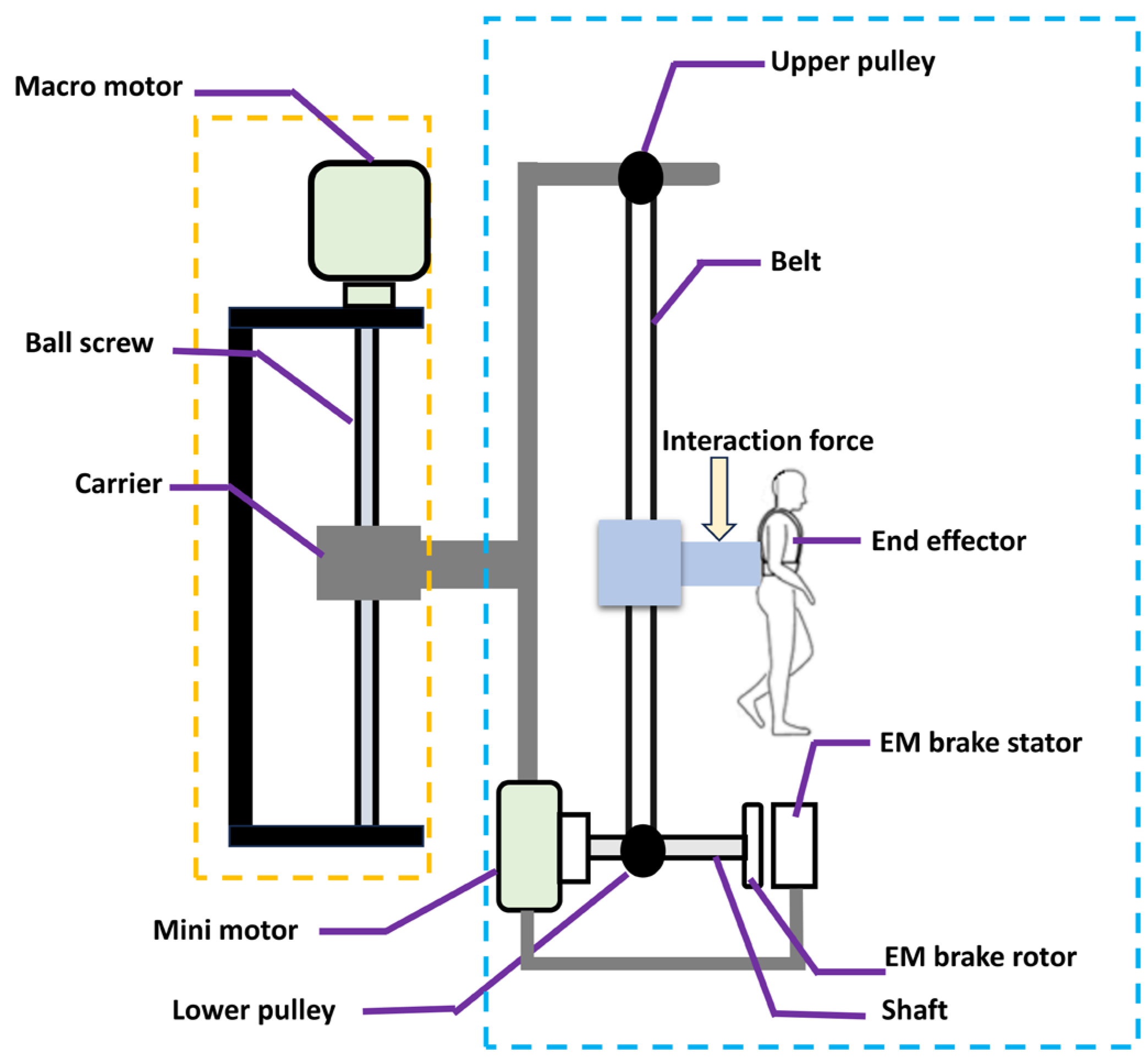
2. Macro–Mini Linear Actuation Concept

2.1. Operating Principle

Figure 2 depicts the concept of the macro–mini linear actuator employing the EM brake. The actuator comprises the high-force unit (macro) and the low-impedance unit (mini). The macro motor propels the vertical displacement of the carrier via the high-force (non-back-drive) ball screw. The end effector is driven by the (low-inertia) mini motor through the highly back-drivable pulley-belt mechanism for high-frequency motion. For an active body-weight-support system for gait training, the end effector of the actuator is connected to a patient’s body through harnesses. The interaction force from the human is applied to the actuator at the end effector. The EM brake rotor is concentrically connected to the same pulley as the mini motor. The stator of the EM brake and the mini motor are mounted on the moving carrier.
For high-transparency (low-force) operation, the brake remains unactuated. The mini motor exclusively propels the end effector through the pulley-belt mechanism, resulting in significantly low mechanical impedance. When a moderate force beyond the capacity of the mini motor is required at the end effector, the damping is modulated by controlling the brake torque against the speed. When the brake is fully locked, no relative motion is allowed between the end effector and the carrier. Therefore, the end effector position is governed by the high-force ball screw. This approach facilitates rapid impedance modulation, enabling full control over the end effector position across the impedance range. Moreover, considering that the macro carrier carries the mini, the system integrates safety measures. The mini unit is integrated with the macro unit to address scenarios where the mini unit faces an abrupt increase in load beyond its capacity or in the event of EM brake failure. In such cases, the end effector gently descends and settles at the lower limit of the carrier. This concept holds significant promise for applications like BWS systems, where robust force support for patients is necessary while allowing freedom of movement.
A dynamic model of the macro–mini linear actuator is derived by considering the diagram in Figure 3. The total displacement at the endpoint x ( t ) is the linear combination between the controlled position x M of the carrier by the macro linear actuator and the translation of the endpoint x m ( t ) with respect to the carrier, as shown in Equation (1).
x ( t ) = x M + x m ( t )
The effective inertia at the endpoint is computed from the endpoint mass m and the moment of inertia J of the rotating components, i.e., EM brake rotor, mini-motor rotor, and pulleys, via the gear ratio of the mini system R . The gravitational force m g , the static friction f , and the viscous damping c 0 are intrinsic properties of the system. The direction of the friction is opposite to the moving direction of the endpoint with respect to the carrier. For a desired damping coefficient c b , the damping force is adjusted by the EM brake proportionally to the translation of the endpoint x m t . By the mini motor, the damping coefficient c m , the torsional stiffness k m , and the equilibrium position x 0 of the endpoint with respect to the carrier can be adjusted. Considering the interaction force at the endpoint F ( t ) and the feedforward torque actuated by the mini motor τ , the equation of motion of the system is obtained by Equation (2).
m + J R 2 x ¨ + c 0 + c b + c m x ˙ + k m x m x 0 = τ R + F t m g f

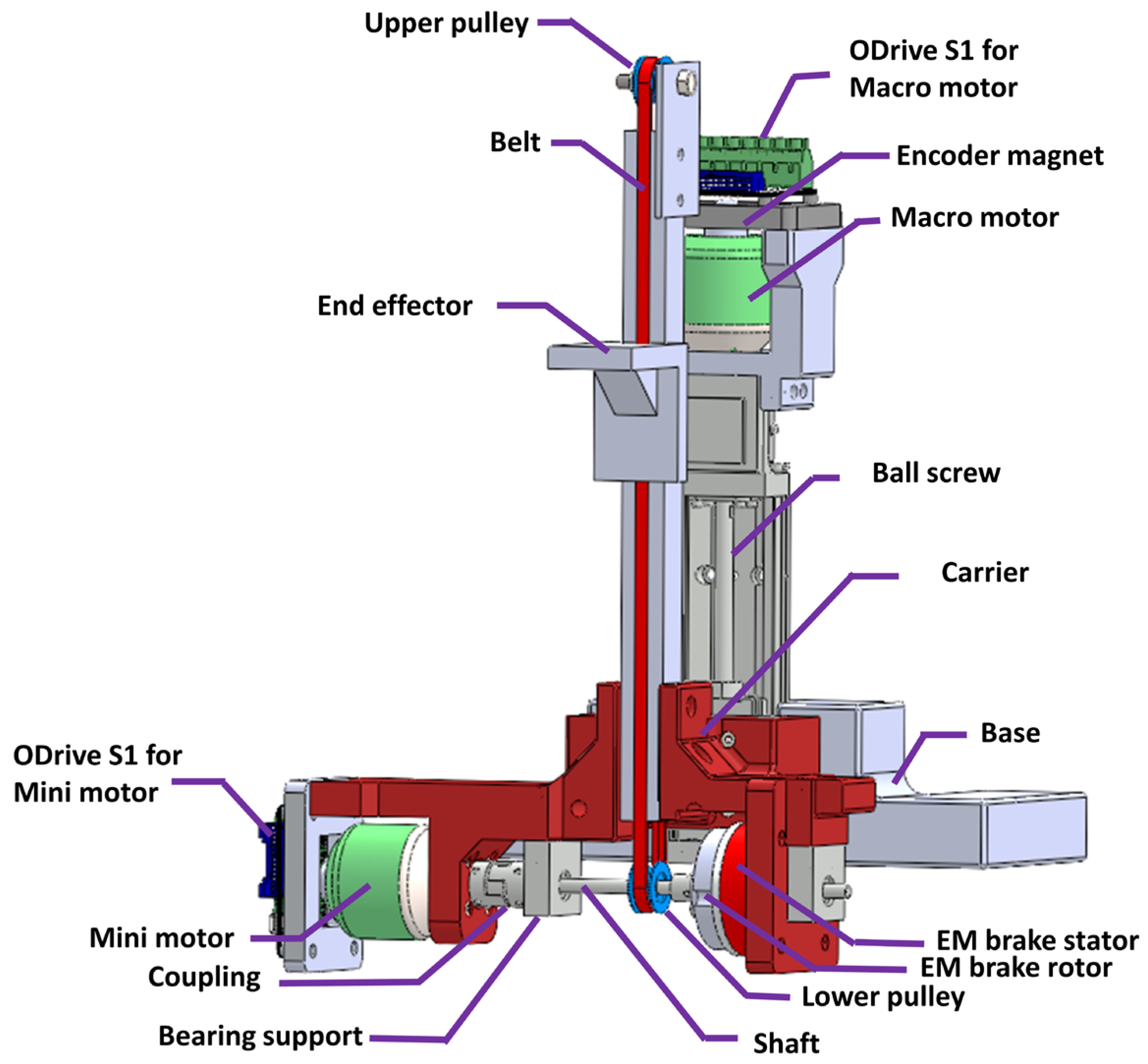
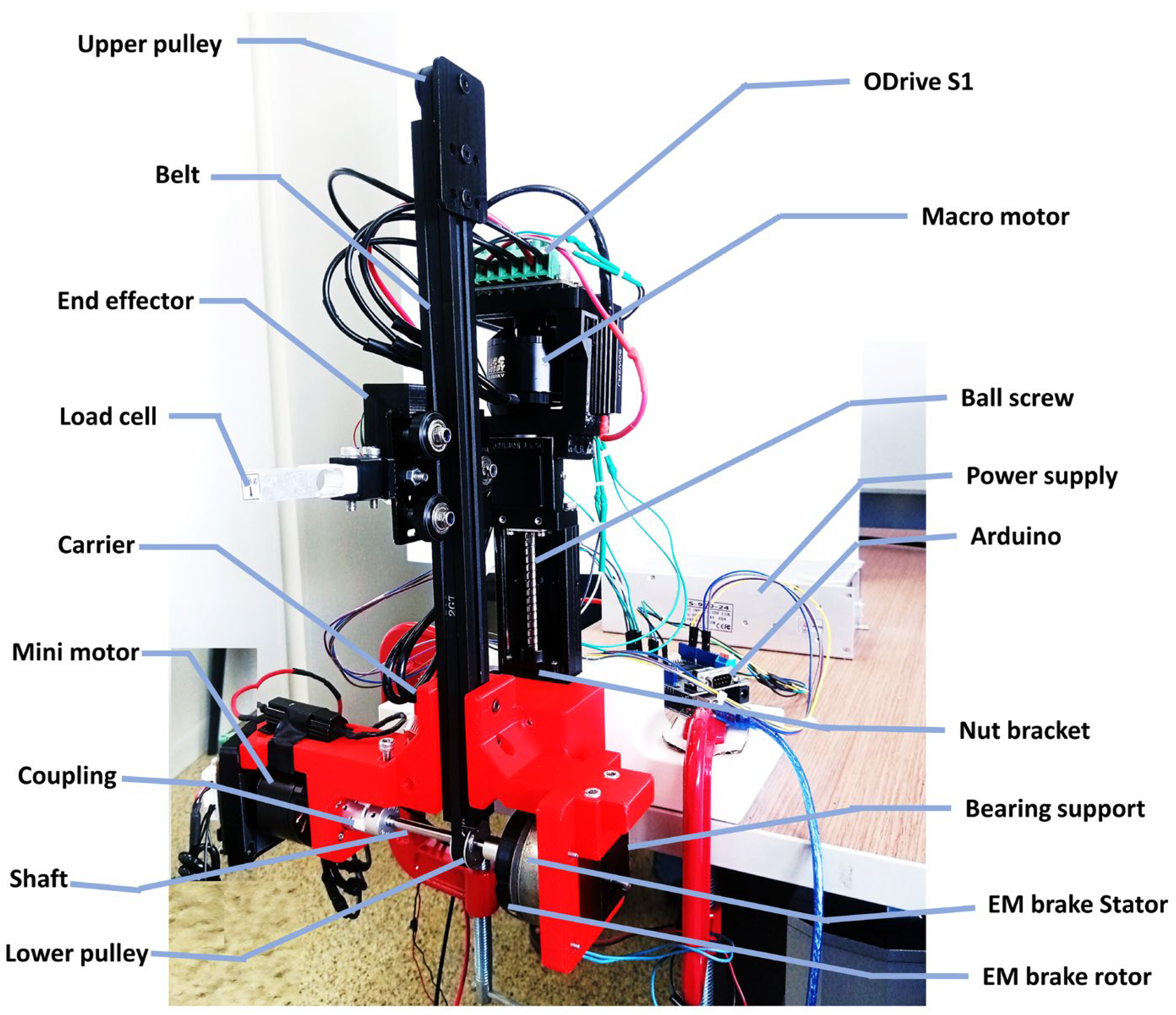
2.2. Hardware Prototype

Figure 4 displays the CAD rendering of the macro–mini linear actuator. For the macro unit, a single-axis actuator (MISUMI’s LX2605, Tokyo, Japan) with a screw shaft diameter of 8 mm, a lead length of 5 mm, and an effective stroke of 72 mm is selected. A custom housing is designed to mount a brushless DC motor (Surpass Hobby’s C5055, Shenzhen, China) for driving the ball screw. The mini assembly is mounted on the carrier, which is affixed to the nut bracket of the ball screw of the macro unit. A pulley-belt mechanism employing a 10 mm radius for both pulleys is utilized on the moving carrier. The vertical translation of the end effector is facilitated by a three-roller slider traveling along the slot of the aluminum extrusion. With this design parameter, the end effector travels around 62.8 mm per revolution of the mini motor’s (or the EM brake rotor’s) rotation. The transmission ratio of the mini system is significantly lower than that of the macro system (around 12.6 times, when considering the 5 mm lead length). For an actual scaled prototype designed for supporting the body weight of a human, the lead length of the ball screw should be decreased (to achieve higher force from the macro system) while the radius of the pulleys can be maintained (or slightly increased), which results in higher differences between the gear ratios of the macro and the mini systems.
The upper pulley is equipped with a bearing to ensure smooth belt operation. The lower pulley is driven by another brushless DC motor (Surpass Hobby’s C5055) via a horizontal shaft with a jaw coupling. Approximately 20 N of force can be exerted at the end effector, while the mini motor delivers 0.2 N·m of torque. The EM brake (SINFONIA’s NB-0.3, Tokyo, Japan) is selected for impedance modulation when the force demanded at the end effector exceeds the capability of the mini motor. With a brake torque of 3 N·m, the maximum load supported at the end effector by the pulley-belt mechanism is approximately 300 N. The EM brake rotor is linked to the horizontal shaft through a custom-designed coupling. The EM brake stator is positioned on the carrier. An appropriate gap (approximately 0.2 mm) between the rotor and stator of the EM brake is necessary to ensure unhindered rotation when the brake is inactive. Two bearing supports are installed for the shaft on both sides of the lower pulley. The hollow structure of the EM brake permits insertion of the shaft, passing through the brake’s rotor and stator to accommodate the bearing support at the end of the shaft.
The alpha prototype of the macro–mini linear actuator was constructed for initial experiments, as depicted in Figure 5. Two brushless motor controllers (ODrive’s S1, El Sobrante, CA, USA) are employed to regulate the macro and mini motors. An encoder magnet is affixed to the rotor shaft of each motor. The ODrive S1, equipped with a 12-bit on-board magnetic encoder (Monolithic Power Systems’ MagAlpha MA702, San Jose, CA, USA), offers real-time data on the motor’s angular position, rotational speed, and current (corresponding to instant torque). During high-transparency operation, the ODrive S1 controls the mini motor, enabling the attainment of the desired stiffness and damping. The end effector driven by the pulley-belt mechanism exhibits extremely low inertia. To engage the EM brake for damping modulation when higher force is needed at the end effector, the rotational speed of the mini motor, matching that of the EM brake rotor, is monitored through the ODrive S1. The Arduino calculates the appropriate PWM command. It transmits to the DC motor driver to supply the corresponding voltage to the EM brake. Detailed information regarding the variation of EM brake torque against rotational speed was presented in our previous study [45].
In this study, position control of the macro carrier is accomplished using the ODrive S1. However, alternative drive solutions may be employed for more straightforward applications. Owing to limitations in the mini motor’s capacity to characterize the damping force generated by the EM brake, we adjusted the setup to enable the macro unit to drive the end effector against the resistance torque of the EM brake, as detailed in Section 4.

3. Hardware Characterization of Mini Unit

A crucial characteristic of the mini actuation unit is back-drivability. The system exhibits high back-drivability when the endpoint inertia, static, and dynamic friction are minimal. Vibration tests were conducted to assess the mini actuation unit’s inertia and damping. The total inertia comprises the inertia of the mini motor’s rotor, the brake rotor, the horizontal shaft, the pulley-belt mechanism, and the end effector. Damping arises from the viscous fluid in the mini motor and all the bearings. Additionally, constant speed tests were conducted at various speeds to validate damping, assess static friction, and examine the effect of gravity.

3.1. Vibration Test

In this experiment, the angular stiffness of the mini motor was configured to 0.1 N·m/rad, while the damping command was adjusted to 0, 0.001, 0.002, and 0.003 N·m·s/rad for the ODrive S1. With this stiffness setting, approximately 20 N of force is needed to displace the end effector 2 cm away from equilibrium (this range is estimated by considering the vertical shift of the body’s center of gravity in the gait cycle of a healthy individual). Each setup was subjected to four repeated experiments. The end effector was displaced from equilibrium and then released suddenly. Subsequently, the end effector vibrated under the influence of virtual spring force, with the vibration gradually diminishing over time. Time-series data of the angular displacement of the mini motor, as observed from the ODrive S1, were recorded. The collected data underwent fitting processes using a linear second-order model. This methodology comprehensively evaluates the system’s dynamic characteristics, providing valuable insights into its inertia and damping.
Figure 6 illustrates the estimated damping plotted against the commanded damping. A positive relationship is evident from the linear trendline. Although the slope of the trendline is not precisely equal to 1, it remains within the same order. The intrinsic damping of the system (stemming from viscous components such as bearings) is discernible from the intersection with the vertical axis, ~0.0025 N·m·s/rad. As depicted in Figure 7, the estimated inertia of the mini actuation system is ~3.9 × 10⁻⁴ kg·m2. The variation in the commanded damping has a negligible influence on the system’s inertia (as indicated by the nearly horizontal trendline).

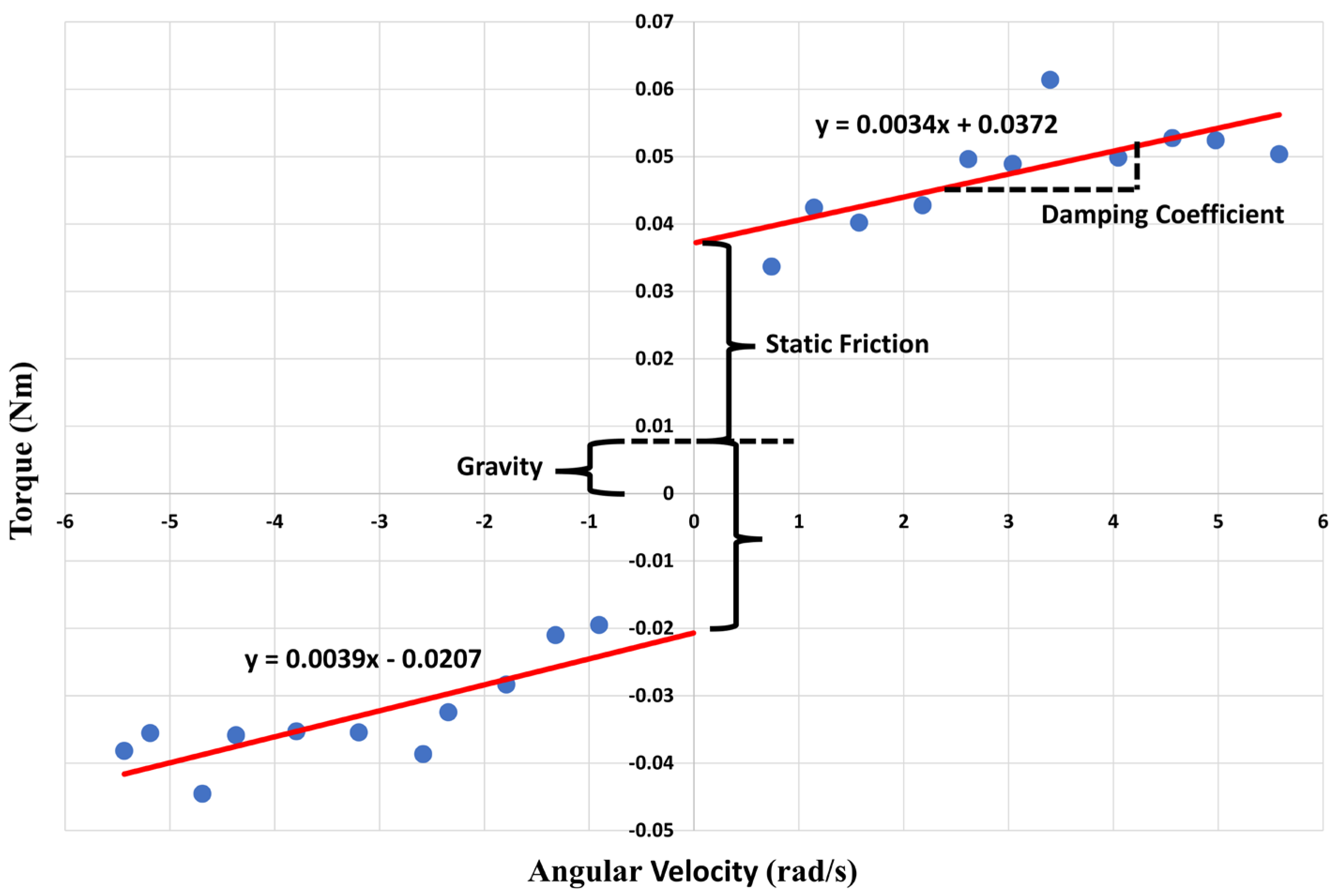
3.2. Constant Speed Test

During this experiment, the mini actuation system was controlled by the ODrive S1 to move the end effector at constant speeds in both upward and downward directions. The torque required from the mini motor to sustain these constant speeds was recorded using the ODrive S1. The average torques obtained from various test speeds are depicted in Figure 8. The slopes of the linear trendlines correspond to the viscous damping coefficients, which are nearly identical (0.0034 N·m·s/rad for upward motion and 0.0039 N·m·s/rad for downward motion). They are similar to the intrinsic damping derived from the vibration test. Since the experiment cannot be conducted at zero speed, extrapolating the linear trendlines from the results of non-zero speed tests can estimate the torque needed from the mini motor to initiate the movement of the end effector from zero speed in both upward and downward directions. For this prototype, static friction is estimated at 0.029 N·m, accounting for half of the offset between the intersections of the upward and downward trendlines with the vertical axis. The static friction is significantly smaller compared to the capacity of the mini actuation system (0.2 N·m). Our system operates vertically under gravity’s influence. The starting torque’s vertical shift is attributed to gravity, approximately equivalent to 0.008 N·m. Without gravity’s effect, the starting torques should be equal for both upward and downward motions.

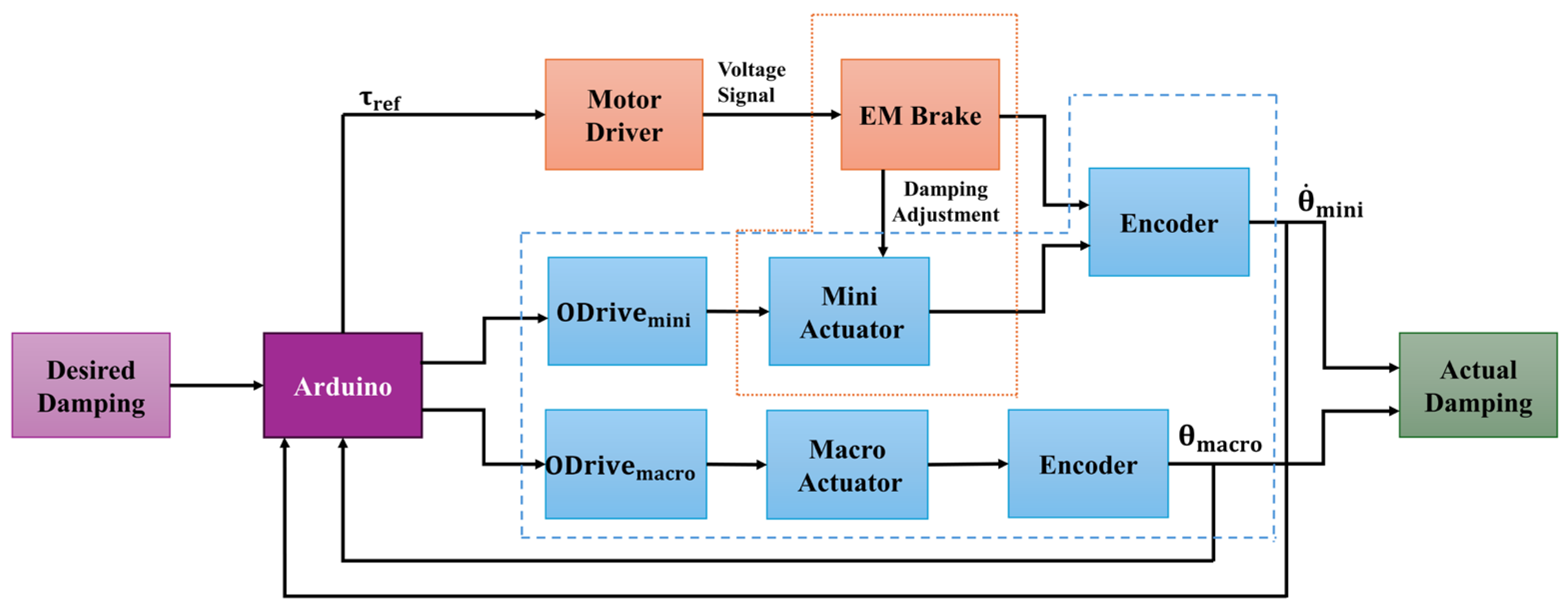
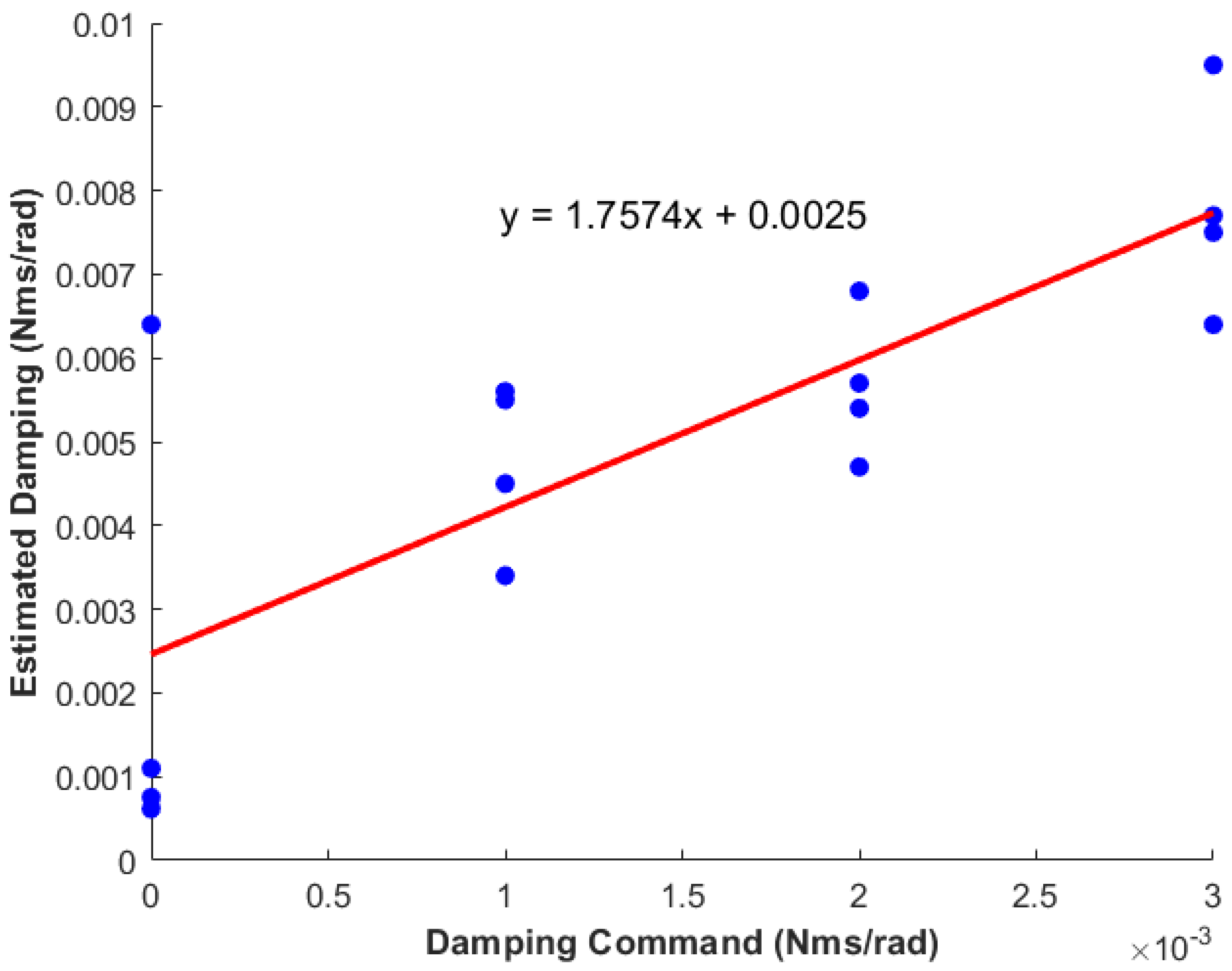
4. Damping Modulation Using an EM Brake

In operational scenarios necessitating force beyond the capacity of the mini actuation system, the EM brake engages the end effector with the high-force unit (macro). The EM brake is regulated to adjust the braking torque following the rotational speed, mimicking the behavior of a mechanical damper. Drawing from our previous study [45], the technical know-how on controlling the EM brake according to the minimum voltage required for its activation is applied in this study.

4.1. Experimental Setup

Owing to the mini motor’s limitation in providing sufficient torque to drive the EM brake across the torque range required for comprehensive characterization, the macro motor was configured to rotate the EM brake. In the initial setup (see Figure 5), a load cell was installed at the endpoint of the mini system to measure the human interaction force. In the setup employed in this section (see Figure 9), the root of the load cell remained mounted on the end effector, while the tip of the load cell was secured to the stationary base. The movement of the endpoint relative to the carrier Y e n d p o i n t c a r r i e r corresponds to the carrier’s movement relative to the base Y c a r r i e r b a s e with an equal magnitude to that of the carrier but an opposite direction to that of the carrier. The motion of the endpoint Y e n d p o i n t c a r r i e r is related to the rotation of the EM brake Δ θ m i n i via Equation (3) for the lower pulley’s radius r p u l l e y . The motion of the carrier Y c a r r i e r b a s e is driven by the rotation of the macro motor Δ θ m a c r o through the ball screw with the lead length “ l e a d ” via Equation (4).
Y e n d p o i n t c a r r i e r = r p u l l e y Δ θ m i n i
Y c a r r i e r b a s e = l e a d 2 π Δ θ m a c r o
The ODrive S1 regulates the desired velocity of the macro motor. This study primarily concentrates on the constant velocity reference and the sinusoidal velocity reference. The rotational speed of the EM brake is determined by monitoring the speed of the mini motor (which shares the same rotational axis as the EM brake rotor). This speed is measured using a 12-bit magnetic encoder and another ODrive S1.
Drawing from our previous study [45], the brake torque τ is related to the commanded pulse-width modulation P W M incorporating the minimum pulse-width P W M o and the initial torque τ 0 , via Equation (5).
τ = s l o p e P W M P W M o + τ 0
For any desired damping coefficient c , the brake torque τ must be proportional to the rotating speed θ ˙ .
τ = c θ ˙
When the required torque is more than the initial torque of the brake, the appropriate pulse-width command PWM is related to the rotating speed of the brake as follows.
P W M = P W M o τ 0 s l o p e + c s l o p e θ ˙
Therefore, the control of the EM brake torque variation against rotational speed is achieved through voltage modulation using the PWM signal. The minimum pulse-width is necessary for EM brakes to generate EM force surpassing the spring force and initiate brake actuation. Additionally, the initial torque of the brake (determined at the minimum PWM) exhibits an offset from zero. The mini actuation unit described in the previous section can meet the demand for low force.

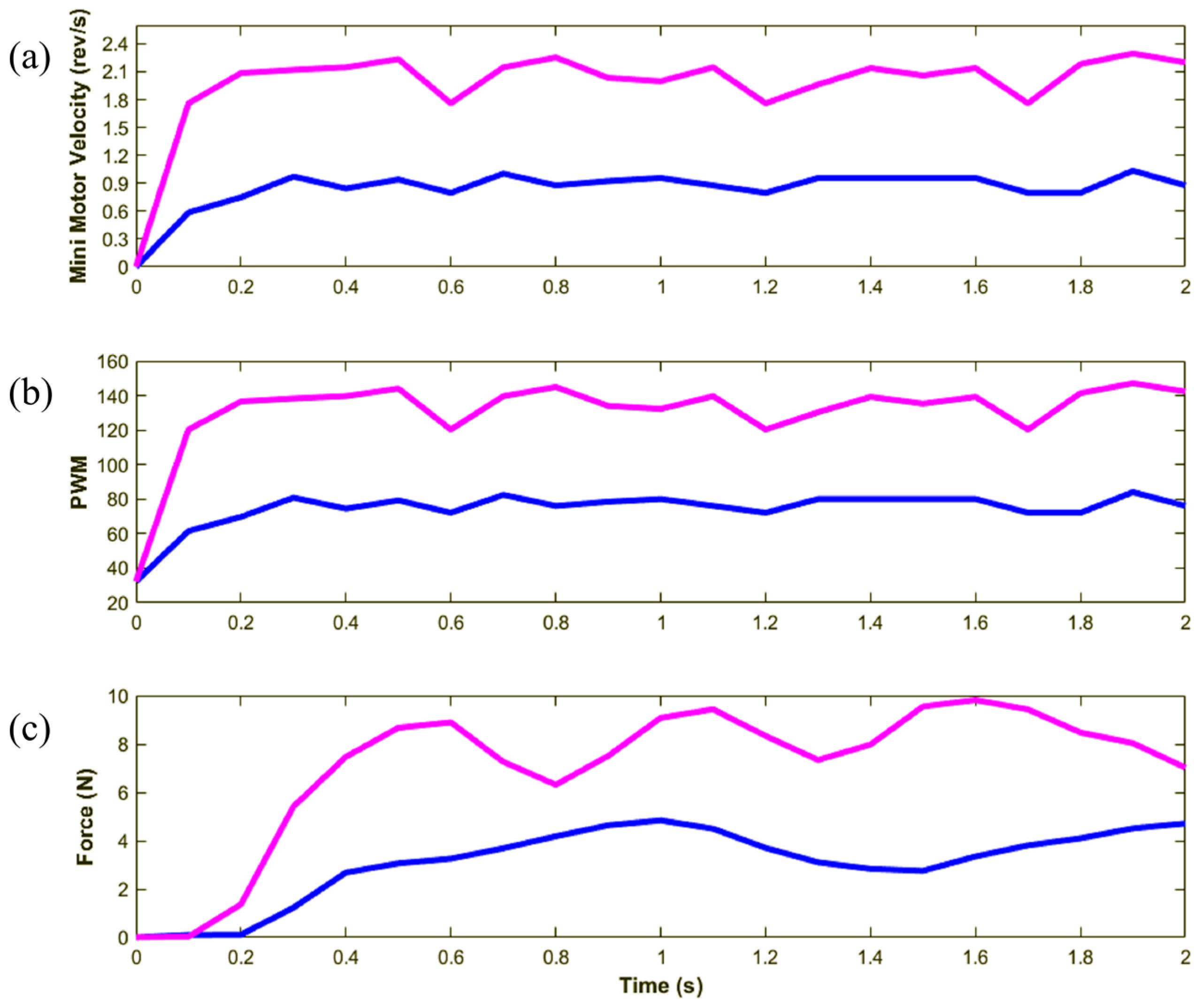
4.2. Constant Velocity Reference

This experiment utilized the macro motor to elevate the carrier at two distinct speeds. Owing to the fixed position of the end effector, linear motion was induced in the pulley-belt mechanism. The rotational speed of the mini motor, which is equivalent to that of the brake rotor, was recorded, as plotted in Figure 10a. The brake torque was adjusted to achieve the desired damping value, with the PWM command computed using Equation (5) and plotted in Figure 10b. At the beginning, when the speed was very low, the computed PWM began from a non-zero value following the first term of Equation (7). The interaction force measured at the stationary endpoint is depicted in Figure 10c. The force increased with increasing speed with a response time of approximately 0.5 s. The force plots exhibited uneven profiles owing to the slight misalignment between the rotor and the brake stator. The frequencies of these fluctuations corresponded to the rotating speeds of the brake.

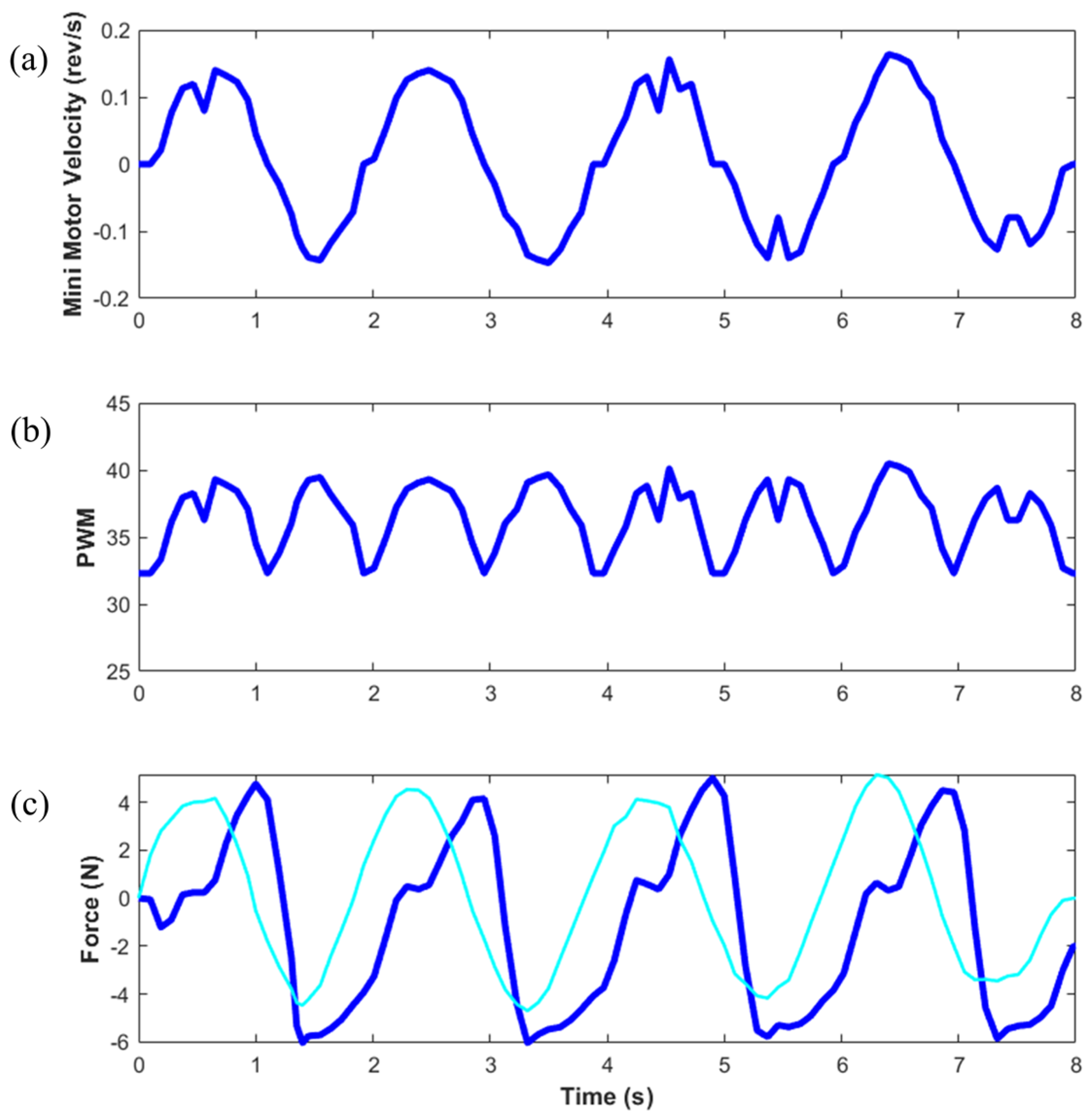
4.3. Sinusoidal Velocity Reference

To validate the damping modulation against a continuous variation in speed, the macro motor was controlled to move the carrier in both upward and downward directions following a sinusoidal pattern, with frequencies of 0.1 and 0.5 Hz. The carrier’s sinusoidal motion closely resembled a human gait cycle. The EM brake torque was modulated based on the real-time speed of the mini motor to simulate an active BWS system. The response of the system to the low-frequency velocity reference (0.1 Hz) was observed for 20 s, as depicted in Figure 11. As shown in Figure 11a, the rotational speed of the mini motor varies between −0.2 and 0.2 rev/s with a period of 10 s. Figure 11b illustrates the PWM command determined solely by the velocity magnitude for clockwise and counterclockwise rotations, as the EM brake consistently generated torque opposite to its rotation. As shown in Figure 11c, the interaction force at the fixed endpoint tracked the sinusoidal velocity reference with a delay (noticeable from the phase shift compared to the ideal force plotted in cyan). The system’s response to the high-frequency velocity reference (0.5 Hz) was observed for 8 s, as depicted in Figure 12. A smoother force response was observed. The load cell measured the endpoint force, which was fixed at one end. A combination of the endpoint weight and the brake torque was converted to the resistant force via the pulley-belt mechanism, resulting in an asymmetric force.
In this study, the different load conditions were applied in terms of the different frequencies of the velocity input to the mini system. The effective control of the EM brake allows the system to adapt the brake torque resulting in the force measured by the load cell at the endpoint that corresponds to the speed variation.

5. Conclusions

This paper introduces a novel concept of a macro–mini linear actuator tailored for supporting human body weight during gait rehabilitation, with a focus on achieving high back-drivability and dynamic modulation of the damping force. The actuator comprises a high-force, non-back-drivable unit (macro), and a low-impedance unit (mini), and it employs a low-inertia motor to drive the pulley-belt mechanism. The mini actuation unit was characterized via vibration and constant speed testing to verify its intrinsically low inertia and friction (static friction and viscous damping). The integration of the EM brake is crucial for enabling the dynamic adjustment of damping. By carefully modulating the EM brake torque in response to speed variations, the actuator demonstrates the capability to promptly and accurately adjust the damping force. Experimental validation is conducted using constant and sinusoidal velocity references. The results reveal a clear relationship between force and speed, underscoring the ability of the actuator to dynamically adjust the damping force across different frequencies.
This approach holds promise for supporting human body weight in rehabilitation settings. Through frequency variation, the proposed actuator can address both elderly individuals’ biomechanical needs at lower frequencies and the needs of physically fit individuals at higher frequencies. The adaptability of the actuator suggests potential integration into various clinical scenarios. Further research is expected to enhance the effectiveness of the actuator across diverse contexts. The prototype presented in this work has a maximum capacity of 300 N while considering the maximum torque provided by the EM brake to engage the low impedance to the high-force units. For an actual scaled prototype of the active body-weight-support system requiring more than 1000 N, around 3–4 times the maximum braking force is required. A more powerful EM brake is suggested in combination with a higher-gear-ratio pulley-belt transmission. A higher torque is also required from the mini motor. The driving force capacity of the mini motor must be traded off with its back-drivability. As compared to high-force actuators using high-gear-ratio transmission with less complexity, the major advantage of this proposed macro–mini linear actuation concept is that the force generated from the mini system might be designed up to 30–40 percent of the macro system’s capacity while maintaining its high transparency. Although in this primary study, the load cell was applied for validation, for practical use in future development, the load cell is a key component gathering interaction force data for switching the mode between low-to-high and high-to-low impedance modes.
It is worth mentioning that the application of this proposed concept of a high transparency linear actuator is not limited to active body-weight-support systems. The macro–mini linear actuator always connecting the mini motor to the endpoint could offer accurate position control for industrial applications, including when high-speed motion is demanded.

Author Contributions

Conceptualization, Z.U., T.S. and R.C.; methodology, Z.U., T.S. and R.C.; software, Z.U. and K.P.; validation, Z.U., T.S. and R.C.; formal analysis, Z.U., K.P. and R.C.; investigation, Z.U., K.P. and R.C.; resources, R.C. and W.W.; data curation, Z.U., K.P. and R.C.; writing—original draft preparation, Z.U. and R.C.; writing—review and editing, Z.U. and R.C.; visualization, Z.U. and K.P.; supervision, R.C. and W.W.; project administration, R.C.; funding acquisition, Z.U., R.C. and W.W. All authors have read and agreed to the published version of the manuscript.

Funding

This research project is partly supported by the Second Century Fund (C2F), Chulalongkorn University, and Thailand Science Research and Innovation Fund, Chulalongkorn University.

Data Availability Statement

The data presented in this study are available on request from the corresponding author. The data are not publicly available due to privacy.

Conflicts of Interest

The authors declare no conflicts of interest.

References

  1. Frey, M.; Colombo, G.; Vaglio, M.; Bucher, R.; Jorg, M.; Riener, R. A novel mechatronic body weight support system. IEEE Trans. Neural Syst. Rehab. Eng. 2006, 14, 311–321. [Google Scholar] [CrossRef] [PubMed]
  2. Wessels, M.; Lucas, C.; Eriks, I.; de Groot, S. Body weight-supported gait training for restoration of walking in people with an incomplete spinal cord injury: A systematic review. J. Rehabil. Med. 2010, 42, 513–519. [Google Scholar] [CrossRef] [PubMed]
  3. Lu, Q.; Liang, J.; Qiao, B.; Ma, O. A New Active Body Weight Support System Capable of Virtually Offloading Partial Body Mass. IEEE ASME Trans. Mechatron. 2013, 18, 11–20. [Google Scholar] [CrossRef]
  4. Van Thuc, T.; Yamamoto, S.-I. Development of a body weight support system using pneumatic muscle actuators: Controlling and validation. Adv. Mech. Eng. 2016, 8, 1–13. [Google Scholar] [CrossRef]
  5. Jungwon, Y.; Novandy, B.; Chul-Ho, Y.; Ki-Jong, P. A 6-DOF Gait Rehabilitation Robot with Upper and Lower Limb Connections That Allows Walking Velocity Updates on Various Terrains. IEEE ASME Trans. Mechatron. 2010, 15, 201–215. [Google Scholar] [CrossRef]
  6. Stienen, A.H.A.; Hekman, E.E.G.; ter Braak, H.; Aalsma, A.M.M.; van der Helm, F.C.T.; van der Kooij, H. Design of a Rotational Hydroelastic Actuator for a Powered Exoskeleton for Upper Limb Rehabilitation. IEEE Trans. Biomed. Eng. 2010, 57, 728–735. [Google Scholar] [CrossRef] [PubMed]
  7. Song, C.; Yang, Y. Nonlinear-Observer-Based Neural Fault-Tolerant Control for a Rehabilitation Exoskeleton Joint with Electro-Hydraulic Actuator and Error Constraint. Appl. Sci. 2023, 13, 8294. [Google Scholar] [CrossRef]
  8. Yap, H.K.; Lim, J.H.; Nasrallah, F.; Goh, J.C.; Yeow, R.C. A soft exoskeleton for hand assistive and rehabilitation application using pneumatic actuators with variable stiffness. In Proceedings of the 2015 IEEE International Conference on Robotics and Automation (ICRA), Seattle, WA, USA, 26–30 May 2015; pp. 4967–4972. [Google Scholar]
  9. Chen, H.; Ma, Y.; Chen, W. Design and Optimization of an Origami-Inspired Foldable Pneumatic Actuator. IEEE Robot. Autom. Lett. 2024, 9, 1278–1285. [Google Scholar] [CrossRef]
  10. Davidson, J.R.; Krebs, H.I. An electrorheological fluid actuator for rehabilitation robotics. IEEE ASME Trans. Mechatron. 2018, 23, 2156–2167. [Google Scholar] [CrossRef]
  11. Kong, K.; Bae, J.; Tomizuka, M. Control of rotary series elastic actuator for ideal force-mode actuation in human–robot interaction applications. IEEE ASME Trans. Mechatron. 2009, 14, 105–118. [Google Scholar] [CrossRef]
  12. Kong, K.; Bae, J.; Tomizuka, M. A compact rotary series elastic actuator for human assistive systems. IEEE ASME Trans. Mechatron. 2011, 17, 288–297. [Google Scholar] [CrossRef]
  13. Abdullahi, A.M.; Haruna, A.; Chaichaowarat, R. Hybrid Adaptive Impedance and Admittance Control Based on the Sensorless Estimation of Interaction Joint Torque for Exoskeletons: A Case Study of an Upper Limb Rehabilitation Robot. J. Sens. Actuator Netw. 2024, 13, 24. [Google Scholar] [CrossRef]
  14. Arents, J.; Abolins, V.; Judvaitis, J.; Vismanis, O.; Oraby, A.; Ozols, K. Human–robot collaboration trends and safety aspects: A systematic review. J. Sens. Actuator Netw. 2021, 10, 48. [Google Scholar] [CrossRef]
  15. Yuan, W.; Hang, K.; Song, H.; Kragic, D.; Wang, M.Y.; Stork, J.A. Reinforcement learning in topology-based representation for human body movement with whole arm manipulation. In Proceedings of the 2019 International Conference on Robotics and Automation (ICRA), Montreal, QC, Canada, 20–24 May 2019; pp. 2153–2160. [Google Scholar]
  16. Hirzinger, G.; Bals, J.; Otter, M.; Stelter, J. The DLR-KUKA success story: Robotics research improves industrial robots. IEEE Robot. Autom. Mag. 2005, 12, 16–23. [Google Scholar] [CrossRef]
  17. Wolf, S.; Hirzinger, G. A new variable stiffness design: Matching requirements of the next robot generation. In Proceedings of the IEEE International Conference on Robotics and Automation, Pasadena, CA, USA, 19–23 May 2008; pp. 1741–1746. [Google Scholar]
  18. Tsagarakis, N.G.; Sardellitti, I.; Caldwell, D.G. A new variable stiffness actuator (CompAct-VSA): Design and modelling. In Proceedings of the IEEE/RSJ international conference on intelligent robots and systems, San Francisco, CA, USA, 25–30 September 2011; pp. 378–383. [Google Scholar]
  19. Javadi, A.; Haghighi, H.; Pornpipatsakul, K.; Chaichaowarat, R. Data-Driven Position and Stiffness Control of Antagonistic Variable Stiffness Actuator Using Nonlinear Hammerstein Models. J. Sens. Actuator Netw. 2024, 13, 29. [Google Scholar] [CrossRef]
  20. Zhao, J.; Wang, Z.; Lv, Y.; Na, J.; Liu, C.; Zhao, Z. Data-driven learning for H∞ control of adaptive cruise control systems. IEEE Trans. Veh. Technol. 2024, 1–15. [Google Scholar] [CrossRef]
  21. Kim, H.K.; Kang, B.; Kim, B.; Park, S. Estimation of multijoint stiffness using electromyogram and artificial neural network. IEEE Trans. Syst. Man Cybern.-Part A Syst. Hum. 2009, 39, 972–980. [Google Scholar] [CrossRef]
  22. Zhang, L.; Li, Z.; Yang, C. Adaptive neural network based variable stiffness control of uncertain robotic systems using disturbance observer. IEEE Trans. Ind. Electron. 2016, 64, 2236–2245. [Google Scholar] [CrossRef]
  23. Seshia, A.A.; Palaniapan, M.; Roessig, T.A.; Howe, R.T.; Gooch, R.W.; Schimert, T.R.; Montague, S. A vacuum packaged surface micromachined resonant accelerometer. J. Microelectromech. Syst. 2002, 11, 784–793. [Google Scholar] [CrossRef]
  24. Azevedo, R.G.; Jones, D.G.; Jog, A.V.; Jamshidi, B.; Myers, D.R.; Chen, L.; Fu, X.-A.; Mehregany, M.; Wijesundara, M.B.; Pisano, A.P. A SiC MEMS resonant strain sensor for harsh environment applications. IEEE Sens. J. 2007, 7, 568–576. [Google Scholar] [CrossRef]
  25. Petersen, K.; Pourahmadi, F.; Brown, J.; Parsons, P.; Skinner, M.; Tudor, J. Resonant beam pressure sensor fabricated with silicon fusion bonding. In Proceedings of the TRANSDUCERS’91: 1991 International Conference on Solid-State Sensors and Actuators, Digest of Technical Papers, San Francisco, CA, USA, 24–27 June 1991; pp. 664–667. [Google Scholar]
  26. Dürig, U.; Gimzewski, J.; Pohl, D. Experimental observation of forces acting during scanning tunneling microscopy. Phys. Rev. Lett. 1986, 57, 2403. [Google Scholar] [CrossRef] [PubMed]
  27. Sardellitti, I.; Park, J.; Shin, D.; Khatib, O. Air muscle controller design in the distributed macro-mini (DM 2) actuation approach. In Proceedings of the IEEE/RSJ International Conference on Intelligent Robots and Systems, San Diego, CA, USA, 29 October–2 November 2007; pp. 1822–1827. [Google Scholar]
  28. Sensinger, J.W.; Weir, R.F.F. Improvements to series elastic actuators. In Proceedings of the IEEE/ASME International Conference on Mechatronic and Embedded Systems and Applications, Beijing, China, 13–16 August 2006; pp. 1–7. [Google Scholar]
  29. Paine, N.; Oh, S.; Sentis, L. Design and Control Considerations for High-Performance Series Elastic Actuators. IEEE ASME Trans. Mechatron. 2014, 19, 1080–1091. [Google Scholar] [CrossRef]
  30. Lee, H.; Lee, J.; Keppler, M.; Oh, S. Robust Elastic Structure Preserving Control for High Impedance Rendering of Series Elastic Actuator. IEEE Robot. Autom. Lett. 2024, 9, 3601–3608. [Google Scholar] [CrossRef]
  31. Zhou, W.; Chew, C.-M.; Hong, G.-S. Design of series damper actuator. Robotica 2009, 27, 379–387. [Google Scholar] [CrossRef]
  32. Scibilia, A.; Pedrocchi, N.; Fortuna, L. Human control model estimation in physical human–machine interaction: A survey. Sensos 2022, 22, 1732. [Google Scholar] [CrossRef]
  33. Goncalves, R.S.; Krebs, H.I. MIT-Skywalker: Considerations on the Design of a Body Weight Support System. J. Neuroeng. Rehab. 2017, 14, 88. [Google Scholar] [CrossRef]
  34. Abdullahi, A.M.; Chaichaowarat, R. Sensorless estimation of human joint torque for robust tracking control of lower-limb exoskeleton assistive gait rehabilitation. J. Sens. Actuator Netw. 2023, 12, 53. [Google Scholar] [CrossRef]
  35. Chaichaowarat, R.; Nishimura, S.; Nozaki, T.; Krebs, H.I. Work in the Time of COVID-19: Actuators and Sensors for Rehabilitation Robotics. IEEJ J. Ind. Appl. 2022, 11, 256–265. [Google Scholar] [CrossRef]
  36. Nishimura, S.; Chaichaowarat, R.; Krebs, H.I. Human-robot interaction: Controller design and stability. In Proceedings of the IEEE RAS/EMBS International Conference for Biomedical Robotics and Biomechatronics, New York, NY, USA, 29 November–1 December 2020; pp. 1096–1101. [Google Scholar]
  37. Chaichaowarat, R.; Nishimura, S.; Krebs, H.I. Design and modeling of a variable-stiffness spring mechanism for impedance modulation in physical human–robot interaction. In Proceedings of the IEEE International Conference on Robotics and Automation, Xi’an, China, 30 May–5 June 2021; pp. 7052–7057. [Google Scholar]
  38. Braun, D.J.; Chalvet, V.; Chong, T.; Apte, S.S.; Hogan, N. Variable stiffness spring actuators for low-energy-cost human augmentation. IEEE Trans. Robot. 2019, 35, 1435–1449. [Google Scholar] [CrossRef]
  39. Wu, Y.; Lan, C. Linear variable-stiffness mechanisms based on preloaded curved beams. J. Mech. Des. 2014, 136, 122302. [Google Scholar] [CrossRef]
  40. Choi, J.; Hong, S.; Lee, W.; Kang, S. A variable stiffness joint using leaf springs for robot manipulators. In Proceedings of the IEEE International Conference on Robotics and Automation, Kobe, Japan, 12–17 May 2009; pp. 4363–4368. [Google Scholar]
  41. Groothuis, S.S.; Carloni, R.; Stramigioli, S. A novel variable stiffness mechanism capable of an infinite stiffness range and unlimited decoupled output motion. Actuators 2014, 3, 107–123. [Google Scholar] [CrossRef]
  42. Wu, X.; Zhao, Z.; Wang, J.; Xu, D.; Chen, W. A novel design of variable stiffness linkage with distributed leaf springs. In Proceedings of the 2016 IEEE Conference Industrial Electronics and Applications, San Francisco, CA, USA, 27 June–2 July 2016; pp. 789–794. [Google Scholar]
  43. Chaichaowarat, R.; Macha, V.; Wannasuphoprasit, W. Passive knee exoskeleton using brake torque to assist stair ascent. In Proceedings of the 2020 IEEE Region 10 Conference (TENCON), Osaka, Japan, 16–19 November 2020; pp. 1165–1170. [Google Scholar]
  44. Chaichaowarat, R.; Nishimura, S.; Krebs, H.I. Macro-Mini Linear Actuator Using Electrorheological-Fluid Brake for Impedance Modulation in Physical Human–Robot Interaction. IEEE Robot. Autom. Lett. 2022, 7, 2945–2952. [Google Scholar] [CrossRef]
  45. Ullah, Z.; Chaichaowarat, R.; Wannasuphoprasit, W. Variable Damping Actuator Using an Electromagnetic Brake for Impedance Modulation in Physical Human–Robot Interaction. Robotics 2023, 12, 80. [Google Scholar] [CrossRef]
  46. Jleilaty, S.; Ammounah, A.; Abdulmalek, G.; Nouveliere, L.; Su, H.; Alfayad, S. Distributed real-time control architecture for electrohydraulic humanoid robots. Robot. Intell. Autom. 2024, 4, 607–620. [Google Scholar] [CrossRef]
Figure 1. System network flow diagram illustrating the configuration of a control system that uses an Arduino Mega 2560 microcontroller to process the data. The orange dashed lines indicate the network comprising the EM brake and the mini actuator, responsible for dynamic damping adjustments. The blue dashed lines denote the network involving the mini and the macro actuators along with their respective sensors (encoders), highlighting the systems’ integrated sensor-network configuration.
Jsan 13 00065 g001
Figure 2. Conceptual design of a high transparency linear actuator utilizing the EM brake to engage the high-force unit (macro) and the low-impedance unit (mini).
Jsan 13 00065 g002
Figure 3. Dynamic model of the macro–mini linear actuator using an EM brake for damping modulation.
Jsan 13 00065 g003
Figure 4. CAD rendering of the macro–mini linear actuator using an EM brake.
Jsan 13 00065 g004
Figure 5. Alpha prototype of the macro–mini linear actuator using an EM brake.
Jsan 13 00065 g005
Figure 6. Damping estimated from the vibration test. At zero damping command, the estimated damping represents an intrinsic property of the system attributed to the viscous components. The total damping exhibits a linear increase with the commanded damping of the mini motor.
Jsan 13 00065 g006
Figure 7. Inertia estimated from the vibration test. The estimated inertia is another intrinsic property of the system, which is constant against the commanded damping of the mini motor.
Jsan 13 00065 g007
Figure 8. Driving torque required from the mini motor to move the end effector at constant speeds. Positive angular velocity corresponds to upward motion and vice versa. The slope of the velocity–torque relationship reflects the intrinsic damping. Static friction is estimated from half of the offset between the intersections of the trendlines with the vertical axis. The influence of gravity is evident in the vertical shift of the starting torque.
Jsan 13 00065 g008
Figure 9. Experimental setup with a fixed end effector to enable the macro motor to generate motion against the EM brake torque. The root of the load cell is positioned on the end effector, while the tip of the load cell is anchored to the stationary base.
Jsan 13 00065 g009
Figure 10. Response to the constant velocity reference at two different speeds. (a) Recorded angular velocity of the mini motor. (b) PWM command for the EM brake. (c) Interaction force is measured by the load cell.
Jsan 13 00065 g010
Figure 11. Response to the sinusoidal velocity reference of frequency 0.1 Hz. (a) Recorded angular velocity of the mini motor. (b) PWM command for the EM brake. (c) Interaction force measured by the load cell. The cyan plot shows the ideal force directly computed from the rotational speed of mini the motor.
Jsan 13 00065 g011
Figure 12. Response to the sinusoidal velocity reference of frequency 0.5 Hz. (a) Recorded angular velocity of the mini motor. (b) PWM command for the EM brake. (c) Interaction force measured by the load cell. The cyan plot shows the ideal force directly computed from the rotational speed of mini the motor.
Jsan 13 00065 g012
Disclaimer/Publisher’s Note: The statements, opinions and data contained in all publications are solely those of the individual author(s) and contributor(s) and not of MDPI and/or the editor(s). MDPI and/or the editor(s) disclaim responsibility for any injury to people or property resulting from any ideas, methods, instructions or products referred to in the content.

