1. Introduction
Long-range directional wake-up radios (LDWuR) can be an important technology for reducing the energy consumption of nodes and improving the communication range in wireless mobile networks. For nodes that must keep their radios on for accepting incoming commands or packet relaying, idle listening can dominate the total energy consumption of the sensor nodes. Although low-power listening MAC protocols have been proposed to reduce idle-listening energy by duty cycling the receiver, they incur long wake-up latency, while the energy consumption is still lower-bounded by the duty cycle. WuRs represent a promising solution to completely eliminating the idle listening cost and significantly extending their lifetime.
We illustrate LDWuR through three examples. Clemson’s Intelligent River project [
1] deploys sensor nodes along the 312-mile Savannah River from the headwaters in North Carolina to the port in Savannah in a large scale. The sensor network provides real-time data on water quality and quantity. The sensor data are important for improving water resources management regarding drinking water and industrial pollutants. The other example is the IBM smart water project [
2], which distributes a sensor network along the 315 miles of the Hudson River to collect and analyze data continuously and in real time. Another example is the flying fox tracking project [
3], where a resourceful base node needs to communicate with resource-constrained collar nodes on demand with the maximum possible range. These applications exemplify long-range sensor network deployments, which motivate us to take the long communication range into account.
To achieve a long communication range of the WuR, we adopt directional antennas to extend communication distance by increasing the antenna gain. As existing low-power WuRs provide short-range communication, they adopt modulation and coding schemes to improve the distance by reducing the packet error rate (PER). However, they provide a limited improvement on the communication range. A directional antenna represents a promising solution that can bring an order of magnitude improvement to communication distance. A directional antenna focuses the radiation beam in one direction to bring more antenna gain. We take advantage of direction antennas to make long-range communication practical.
The challenge with adopting directional antennas is to search the direction in which the transmitter locates. As the directional antenna focuses the radiation beam in one direction, the transmitter might not lie in the same direction. This incurs the overhead of a motor to rotate the antenna in all directions [
4]. To address this, our proposed LDWuR adopts static and dynamic strategies. A static strategy means that the LDWuR uses multiple directional antennas in different directions. A dynamic strategy means that the LDWuR uses multiple omnidirectional antennas that cooperate to form beams in different directions. To evaluate our LDWuR and strategies, we design a MAC protocol and system model to investigate salient characteristics in terms of total power consumption and latency. We design an active LDWuR. Our design is a battery-powered radio. It employs the same battery with the node’s data radio. For a long-range communication application in wireless mobile networks, the requirements of WuR are two-fold. First, we adopt high-gain directional antennas to enhance the communication range with the same power consumption. The characteristic of the directional antenna supports less interferences from other directions, which improves the wake-up signal and noise ratio. From the relationship of the power consumption and packet rate in
Figure 7a, our design consumes about 0.0276 W with short data packets at a packet rate of one packet per second. Its power consumption is close to the existing work [
5]. Our WuR design still needs to be optimized to reduce its power consumption further to compare with existing WuRs. That will be our future work. Second, our WuR adopts the minimum number of the antenna to explore and point the transmitter. For static antennas, we adopt four directions to cover the entire range. For dynamic antennas, we adopt three omnidirectional antennas that form a beam with about a 90° cover area. That is the minimum cost of extra antennas for a long-range communication application in wireless mobile networks.
Our contributions are as follows. First, we propose adopting directional antennas to enhance the communication range of an LDWuR for long-range applications. Second, we design two strategies to search the transmitter’s location for extending the antenna’s cover range. Third, we develop the system model and event-driven MAC protocol to evaluate the performance of our design in terms of total power consumption and latency.
The reminder of this paper is organized as follows.
Section 2 surveys related literature. In
Section 3, we introduce our proposed LDWuR and describe our strategies to explore the transmitter’s direction. Then, we carry out a theoretical analysis of our system model and salient characteristics of the MAC protocol for two case studies.
Section 4 presents the LDWuR hardware and design principle. Finally, we evaluate our design and event-driven MAC protocol through the case study of Wi-Fi power savings in
Section 5.
2. Related Work
This section reviews existing WuRs’ communication technologies and design metrics. WuRs have been proposed to improve PER and communication range for IoT and WSN applications. We review modulation, addressing, channel coding and beamforming techniques.
2.1. Modulation and Addressing
Some studies have explored solutions to improve the PER of WuRs through different modulation techniques, such as pulse-width modulation (PWM) [
6] and pulse position modulation (PPM) [
7], while other studies investigate address-coding schemes [
8,
9]. However, they achieve limited modulation gain and increase the power consumption by the longer wake-up sequence of 31 to 48 bits to maintain a probability of detection of 90%.
The address-coding scheme from the work [
9] maintains the desired probabilities of detection (
) of 90% by increasing the bits of the wake-up sequence. The wake-up sequence consists of a pseudo-noise (PN) code sequence of length N. The PN code supports low correlation with other sequences, which avoids a false alarm (FA) from other communicating nodes or wake-up signals for neighbor nodes. To maintain a constant
of 90%, they adjust the correlator threshold and RF input power level. If N is 31 bits, the mean time between FAs is about 10 s at the given RF input power of
dBm and a constant
of 90%. At the same condition, if N is seven or 15 bits, the mean time between FAs is about 0.1 s. Therefore, increasing the bits of the wake-up sequence reduces FAs in a certain time.
2.2. Channel Coding
Some existing studies propose a variety of channel coding and forward error correction (FEC) methods to improve bit error rate (BER) and PER for wireless and optical communication. Proakis
et al. [
10] proposed the Hadamard codes as a way to improve the probability of bit error over block orthogonal code on a Rayleigh fading channel with a bandwidth constraint. The Hadamard code achieves better performance than the block orthogonal code does at the cost of an increase in decoding complexity. Djordjevic
et al. [
11] proposed two novel classes of optical orthogonal code (OOC) for synchronous and asynchronous incoherent optical CDMA (OCDMA). The proposed OOC scales well with the number of users. Faruque [
12] proposed the error control coding using orthogonal codes. From bandwidth efficiency analysis, a specific length of orthogonal codes mentioned by the author provides an error correction scheme without bandwidth expansion by partitioning data into blocks at the expense of complexity. The same author [
13] later proposed orthogonal on-off keying (OOOK) for free-space laser communication. A block of data is mapped into a block of bi-orthogonal code, which provides the error correction capability through a correlation process. However, these designs do not consider the sensitivity, power consumption and latency. Pursley
et al. [
14] explored increased interference rejection capability for channels with multiple access or multipath interference. From the results, the 64-ary orthogonal modulation shows better performance than binary phase-shift keying (BPSK) does for the turbo product code at a rate of 0.793 at PER comparison. However, the use of orthogonal modulation and turbo product code increases the implementation complexity. All of the above studies are for wireless communication in general, but are not specific to WuRs. The generality increases implementation complexity and may be impractical for WuRs.
2.3. Beamforming
Several studies have been proposed to optimize beamforming vectors and power configurations [
15,
16,
17,
18] for improvement of the information and energy transfer. However, they do not take WuRs into account. The most relevant work is by Trösch
et al. [
19]. They take advantage of multiple ultra-wideband impulse radios (UWB-IR) statically mounted on the wall forming a circle that cover all semi-active sensor nodes inside. Multiple UWB-IRs create the beamforming to trigger the wake-up detector of a semi-active sensor node. However, they do not consider the scenario of mobile UWB-IRs and sensor nodes.
2.4. Wi-Fi Power Savings
Hiroyuki Yomo
et al. [
5] designed a WuR mainly to save the power of idle Wi-Fi access points. However, they do not take power savings of the station side into account. Oller
et al. [
20] proposed an IEEE 802.11-enabled device as the WuR transmitter and the low-power WuR receiver. However, the WuR receiver supports the limited sensitivity and communication range. For energy-constrained station-side and long-range communication, we propose our Wi-Fi MAC protocol and strategies to save power on energy-constrained devices, such as mobile phones, tablets, laptops,
etc.
This work is an extended work based on our previous design [
21] for long-range communication scenario in wireless mobile networks. Previous work adopts an omnidirectional antenna that supports less antenna gain than a directional antenna. Using an omnidirectional antenna, one can receive interferences from all directions. However, previous works cannot support a longer range and less interference for wireless mobile networks.
The main contributions of this paper are three-fold. First, we enhance the communication range of our WuR by directional antennas or beamforming. Second, WuRs collaboratively detect the transmitter’s location and receive the wake-up signal sending from the transmitter by static or dynamic strategies without receiving interferences from other directions. Third, we propose the MAC protocol for Wi-Fi power savings. To our knowledge, no research exists addressing WuRs and beamforming for wireless mobile networks.
3. Theoretical Analysis
We first present the system model analysis to determine the block orthogonal code’s PER , throughput, power consumption and latency. Second, we analyze two strategies to detect the transmitter’s direction for mobile networks in the case study. Third, we propose the MAC protocol based on our LDWuR to enhance Wi-Fi power savings in the other case study.
3.1. System Model
The system is modeled as the transmitter transmitting the input signal
X of block orthogonal codes through an additive white Gaussian noise (AWGN) channel and the receiver receiving the signal
Y. One purpose of the model is to find the symbol error probability of the block orthogonal codes. From the symbol error probability, we find the packet error probability of the block orthogonal codes (
Section 3.2) and compare it with existing schemes. The received signal
Y through the AWGN channel is given by:
where
β is the attenuation from the AWGN channel with a Gaussian distribution,
is the ideal pattern of the block orthogonal codes’ symbols for data bit zero and one,
τ is the correlation time period and ⊗ is the correlation operation.
The block orthogonal codes use chips per symbol () and oversampling factor () to suppress noise. The reduces the noise variance (noise power) by a factor of . The block orthogonal code can be represented as the M-ary block orthogonal codes with diversity , where , and is the number of chips per symbol.
The average signal-to-noise ratio per chip,
, is given by:
where
is the signal-to-noise ratio per bit. The symbol (code word) error probability,
for
M-ary block orthogonal signaling is given by:
where
is the number of chips that can be corrected by
M-ary block orthogonal signaling:
The minimum Hamming distance
, with diversity
L, is given by:
the chip error probability of coherent OOK modulation,
, through a matched filter is given by [
22]:
The value of
is given by:
3.2. Symbol Error Rate and Packet Error Rate
To compare the block orthogonal codes with other schemes, we analyze the packet error probability from Equation (
3). The packet error probability of the block orthogonal codes,
, is given by:
where
denotes the wake-up packet length in bits. To explore the performance of the varying modulation and encoding schemes, we analyze their symbol error rate (SER) and PER. For PWM modulation, we use the BER in [
6]. In terms of other encoding schemes, we apply the system model in [
23] to analyze their SER and PER. The relation between the symbol error probability,
, and bit error probability,
, of binary coherent OOK modulation through a matched filter is given by:
The packet error probability of OOK modulation with 8B10B coding,
, is given by:
The packet error probability of OOK modulation with Hamming
code,
, that can detect and correct one error is given by:
3.3. Throughput
For a performance comparison of the block orthogonal codes with other modulation schemes and encodings, we will now analyze the respective throughputs. Reducing PER by channel coding can enhance the throughput of WuR. Lower PER of WuR can receive more successful wake-up packets. This means that WuR has a higher throughput. Therefore, the wake-up time can be shorter. In other words, the WuR can receive more information in a certain time. The PER of WuR is caused by false wake-ups and missed wake-ups.
To clarify the false wake-ups or missed wake-ups, we define true positive, false positive, true negative and false negative for WuR. Positive means the WuR receives the wake-up signal. Negative means the WuR does not receive the wake-up signal. True positive means that the transmitter sends a wake-up signal and the WuR receives a wake-up signal. False positive means that the transmitter does not send a wake-up signal and the WuR receives any other wake-up signal, also called a false alarm or false wake-ups. True negative means that the transmitter does not send a wake-up signal and the WuR does not receive a wake-up signal. False negative means that the transmitter sends a wake-up signal and the WuR does not receive any wake-up signal, also called a miss detection or missed wake-ups. The false wake-ups and missed wake-ups lead to the PER of WuR. They are discussed in cases 1a and 1b of previous work, respectively [
24].
We assume the system bandwidth as the noise bandwidth
, that the wake-up packet length is
bits, that the transmitter sends
wake-up packets and that the packet reception rate (PRR) of the WuR is given by:
where
is the WuR’s PRR and
is the WuR’s packet error probability with varying modulation types and encodings. The throughput
is given by:
3.4. Power Consumption
Our approach to evaluating power consumption for the purpose of comparing WuRs is to analyze how effectively they implement the given wake-up protocol [
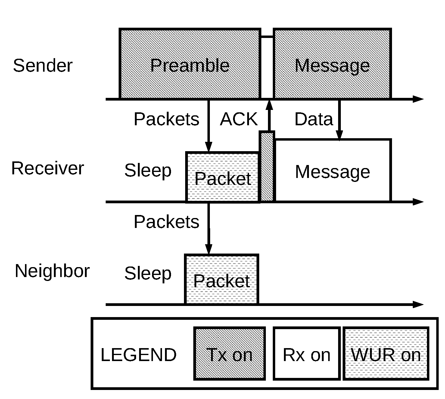
24] in terms of total power consumption and latency. The wake-up protocol as illustrated in
Figure 1 will show that the PER is an important metric. We find the optimal preamble time
to achieve the minimum power consumption through a single-hop network with neighbors.
We assume the number of WuRs
to be the number of neighbor nodes
. The optimal preamble time duration,
, is given by [
24]:
where
includes consecutive wake-up packets to the receiver’s WuR,
is the WuR’s power consumption,
is the data radio’s transmission power, PR is the packet rate,
is the expected transmission time and
is the wake-up packet’s time duration.
Figure 1.
Wake-up protocol.
Figure 1.
Wake-up protocol.
The total power consumption,
, is given by [
24]:
where
represent the probabilities of three cases: WuR with packet error, data radio with packet error and WuR and data radio both with all correct packets, respectively.
represent the respective power consumption, and
is the idle listening power consumption.
Equation (
15) shows that the high
will have more expected transmission times
, then
will increase. Higher PER WuRs will increase power consumption significantly, as they have more
and wake-up packet retransmissions
. Moreover, they wake up the respective higher-power data radios.
3.5. Latency
To compare the latencies of existing WuRs, we implement the given wake-up protocol to determine the total latency instead of the component’s propagation delay time in the WuR circuit. Therefore, the latency emphasizes the important metric PER again. Latency is defined as the time duration between transmission and successful reception of the WuR packet. The optimal preamble time period
for our wake-up protocol [
24] is designed to achieve the lowest power dissipation for respective existing WuRs. Moreover, the
should at least include the eight symbols to represent the wake-up address of 16 bits for addressing 65,536 nodes.
We assume that latencies are the same when the false and successful wake-up signals occur. The WuR’s total latency,
, is given by [
24]:
where
is the message time duration. When the transmitter sends a message to the receiver’s data radio, the receiver spends
for receiving the message from the transmitter.
For low-power WuRs with a higher PER, they have larger , as they require more of wake-up packets. Therefore, they increase the total latency significantly.
3.6. Case Study: Transmitter Localization by LDWuR for a Mobile Network
We propose two strategies to detect the transmitter’s direction for mobile networks. One strategy is static antennas. The other strategy is dynamic antennas.
3.6.1. Static Antennas
The receiver adopts the number of LDWuRs in different directions. The receiver polls each LDWuR for each direction in turn to explore the transmitter’s direction. The average total power consumption is the same as WuRs Equation (
15) with a larger cover range. The average total power consumption,
, is given by:
where
represents the scan time for each direction and
is the number of different directions, which means the number of LDWuRs. For example, the receiver adopts four LDWuRs in different directions, such as east, south, west and north. Equation (
17) shows that LDWuRs consume the same power consumption to explore the transmitter’s direction.
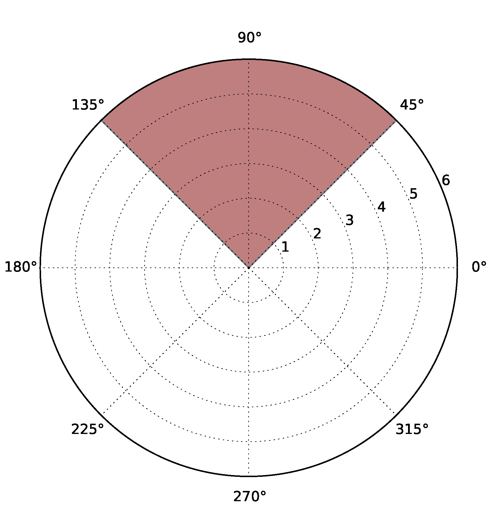
Figure 2 shows that one of four LDWuRs scans the north direction with 90°.
Figure 2.
One of four long-range directional wake-up radios’ (LDWuRs) scans the north direction.
Figure 2.
One of four long-range directional wake-up radios’ (LDWuRs) scans the north direction.
The total latency is
times the total latency of WuRs Equation (
16), as the receiver spends more time on the scan of each direction. The total latency is given by:
3.6.2. Dynamic Antennas
In this strategy, the receiver adopts multiple LDWuRs. Each LDWuR consists of a WuR built in an omnidirectional antenna. Multiple LDWuRs cooperate to steer a beam in different directions in turn. Therefore, the receiver can use a beam to detect the transmitter’s direction.
The average total power consumption is the same as WuRs Equation (
15) with a larger cover range. The average total power consumption,
, is given by:
where
represents the scan time for each direction of beam,
is the number of omnidirectional antennas and
is the number of different directions of beams. For example, the receiver adopts three LDWuRs to cooperate to form a beam in different directions with a certain degree of cover range. Equation (
19) shows that the receiver adopts
LDWuRs with
antennas of
times power consumption to explore the transmitter’s direction.
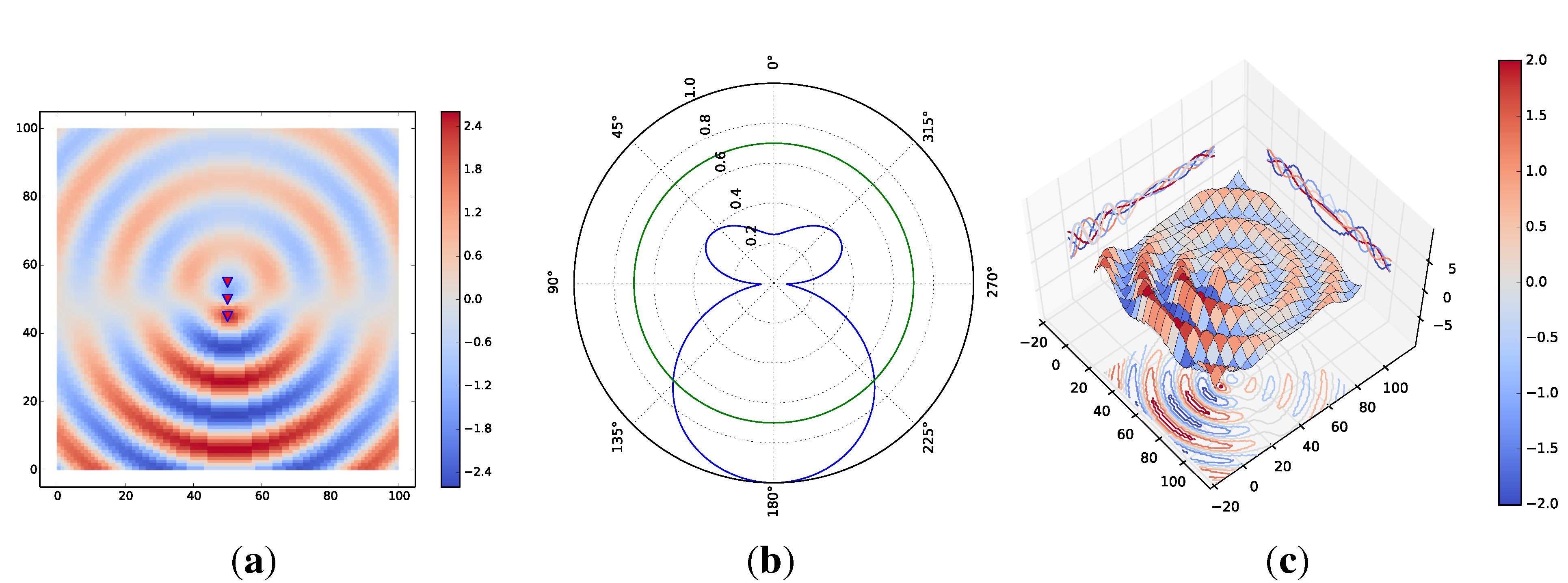
Figure 3a shows that three LDWuRs cooperate to steer a beam in the south direction with a normalized spacing of five units, a related phase delay of seven units and beam pattern size of 90° at a normalized signal strength of 0.7.
Figure 3b shows the beam pattern size and signal strength level of 0.7.
Figure 3c shows the 3D beam pattern with the same parameters.
Figure 3.
Three LDWuRs cooperate to form the beamforming. (a) 2D beam pattern; (b) beam pattern size; (c) 3D beam pattern.
Figure 3.
Three LDWuRs cooperate to form the beamforming. (a) 2D beam pattern; (b) beam pattern size; (c) 3D beam pattern.
The total latency is
times the total latency of WuRs Equation (
16), as the receiver spends more time on the scans of each direction. The total latency is given by:
3.7. Case Study: Wi-Fi Power Savings by LDWuR
To adopt our LDWuR for Wi-Fi power savings, we take advantage of the event-driven mechanism in the proposed LDWuR protocol.
Figure 4 shows a block diagram of the proposed LDWuR for Wi-Fi power savings. The access point sends a wake-up signal to the station. The station receives the wake-up signal and turns on the high-power Wi-Fi module.
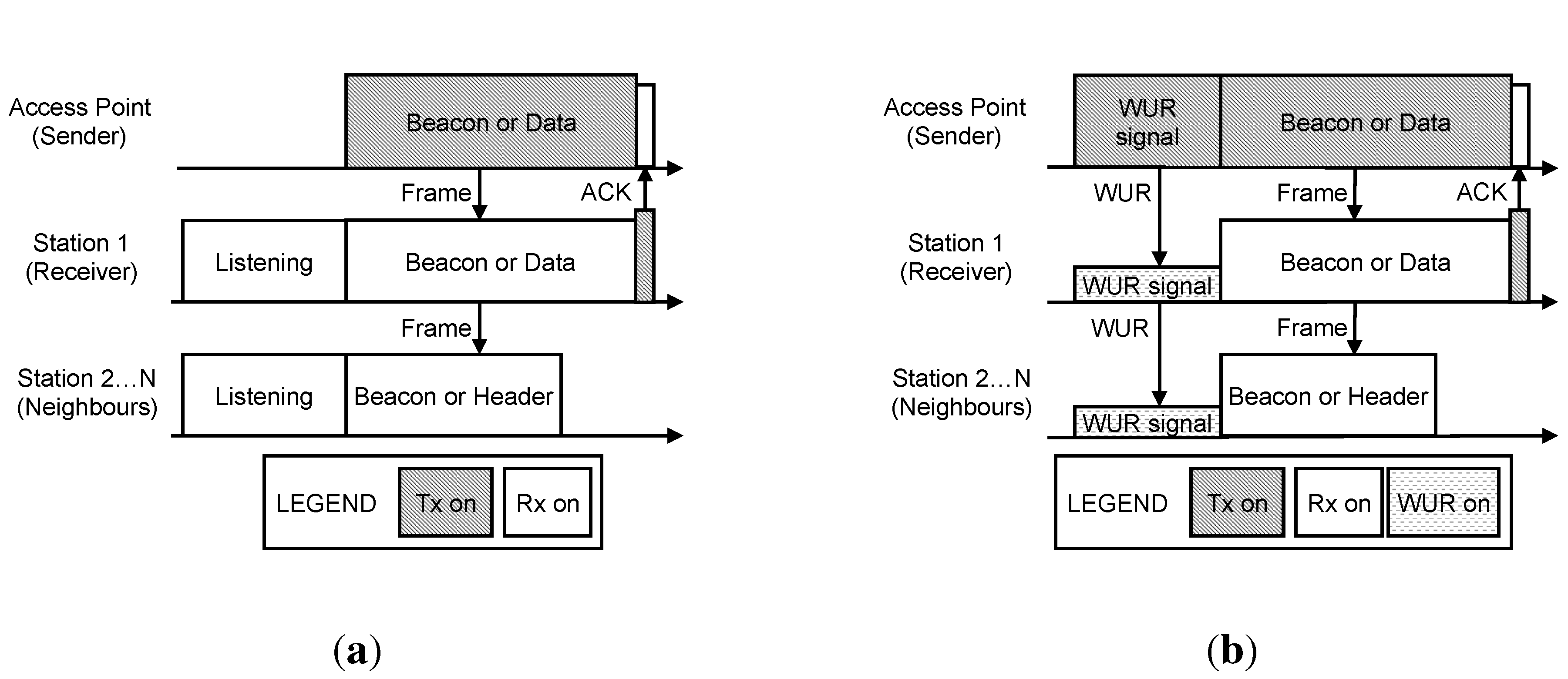
Figure 5a shows a conventional MAC protocol. The station keeps an RF front-end on all of the time to ensure that the station can receive a beacon or data frames on time. This means that it induces a high-power consumption on idle listening for a beacon or data frames.
Figure 5b shows the proposed MAC protocol. The station adopts low-power LDWuR to reduce the power consumption on receiving a beacon or data frames. The wake-up signal includes the station ID to wake up the receiver. Neighbors overhear the header of the beacon or data frames to determine whether to turn off the data radio immediately.
Figure 4.
Overview of LDWuR for Wi-Fi power savings.
Figure 4.
Overview of LDWuR for Wi-Fi power savings.
Figure 5.
Comparison of the proposed MAC protocol with a conventional MAC protocol. (a) Conventional MAC protocol; (b) proposed MAC protocol.
Figure 5.
Comparison of the proposed MAC protocol with a conventional MAC protocol. (a) Conventional MAC protocol; (b) proposed MAC protocol.
4. Hardware Design
This section describes the hardware circuit board and the design principle for our proposed LRWuR. To wake up the desired radio, the transmitter sends a wake-up signal in a packet that encodes the 16-bit wake-up identification (ID) value and 24-bit additional out-of-band data for a total of 40 bits. If the wake-up ID matches the node ID, the wake-up radio sends an interrupt signal to wake up the receiving node’s MCU. Then, the transmitter will send a message to the data radio. If the wake-up ID does not match the node ID, the receiving radio ignores the wake-up signal and waits for the next wake-up signal. Thus, the latencies are the same whether a false or successful wake-up signal is received.
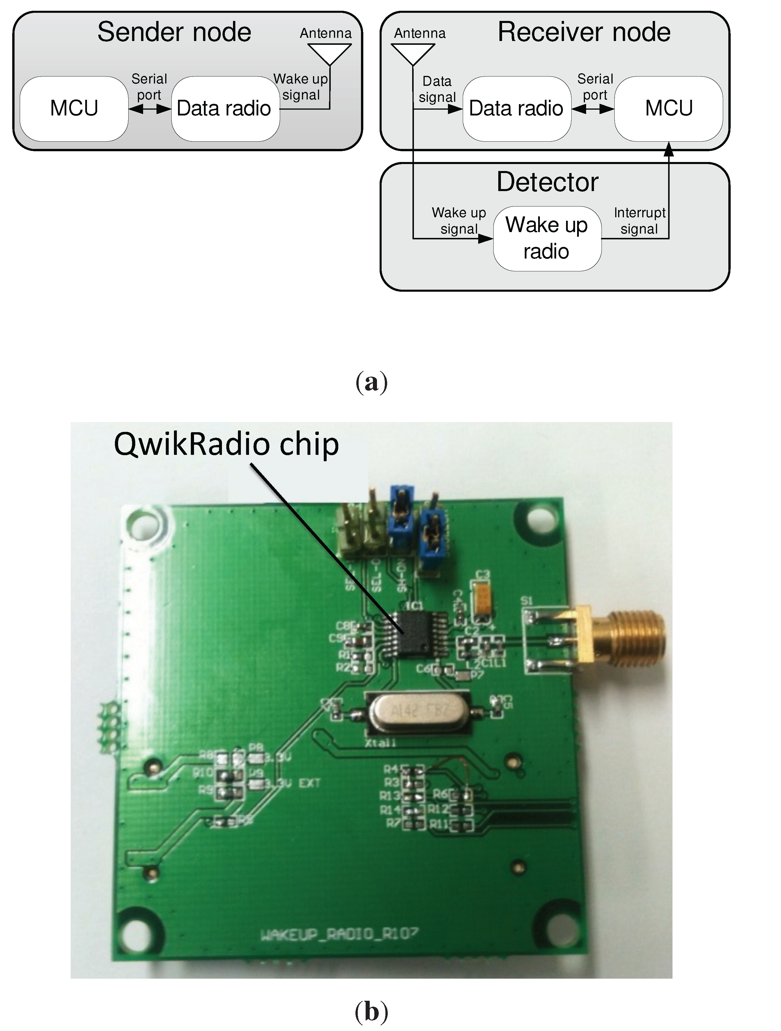
Figure 6a shows the block diagram, while
Figure 6b shows a photo of the prototype. The sender node consists of a microcontroller unit (MCU) and an IEEE 802.15.4 data radio. The MCU encodes the data with a spreading code and uses the data radio to send an OOK-modulated data sequence to the receiver node. As with previous wake-up radio proposals, we select OOK modulation rather than more complex schemes, since it requires simple hardware and has a low implementation cost. The spreading code scheme consists of 16 chips for each pattern (symbol
A or symbol
B). Symbols
A and
B represent binary one and zero, respectively. The receiver node employs the wake-up radio to decode the signal using the same spreading code to obtain the wake-up bit sequence.
Figure 6.
LDWuR prototype. (a) Block diagram of LDWuR and nodes; (b) circuit board.
Figure 6.
LDWuR prototype. (a) Block diagram of LDWuR and nodes; (b) circuit board.
We use simple components to implement the proposed LRWuR with proper settings on capacitors and the crystal for the wake-up radio’s bandwidth. Our wake-up radio prototype is separate from the sensor node with a built-in main data receiver. It includes a Fleck3b [
25] circuit board and an off-the-shelf OOK receiver QwikRadio [
26] circuit board. The OOK receiver includes the image-rejection filter, amplifier, AGC (Automatic Gain Control) and OOK demodulation. The OOK receiver circuit board includes impedance matching and a band pass filter for the OOK receiver. The demodulator’s bandwidth configuration can be adjusted through jumpers and capacitors on the OOK receiver circuit board. The demodulation bandwidth is set at 6.85 kHz with 22-nF and 1-
μF capacitors. The crystal, the reference clock at 14.29983 MHz for all of the OOK receiver’s internal circuits, provides the carrier frequency at 916.5 MHz. To improve the sensitivity, our wake-up radio prototype uses a Fleck3b circuit board to process the block orthogonal codes’ algorithm.
Other existing wake-up radios [
8,
27,
28,
29,
30] are also applicable if they are tuned to operate at a frequency of 916.5 MHz and a low data rate below 10 kbit/s. The designer can choose a proper OOK receiver to be an alternative solution. In terms of the transmitter, the designer can select any IEEE 802.15.4-compliant data radio to operate at two frequency channels of 916.5 MHz, 916.5
0.2 MHz and a data rate of about 20 kbit/s to be the other design option.
5. Performance Evaluation
To evaluate our LDWuR and MAC protocol, we exemplify a case study to observe the packet rate and the beacon interval effects on the power consumption and latency. We also compare our LDWuR with existing WuRs [
5,
20]. The simulation parameters refer to existing studies and datasheets [
24,
26,
31].
5.1. Case Study: Wi-Fi Power Savings by LDWuR
5.1.1. Power Consumption
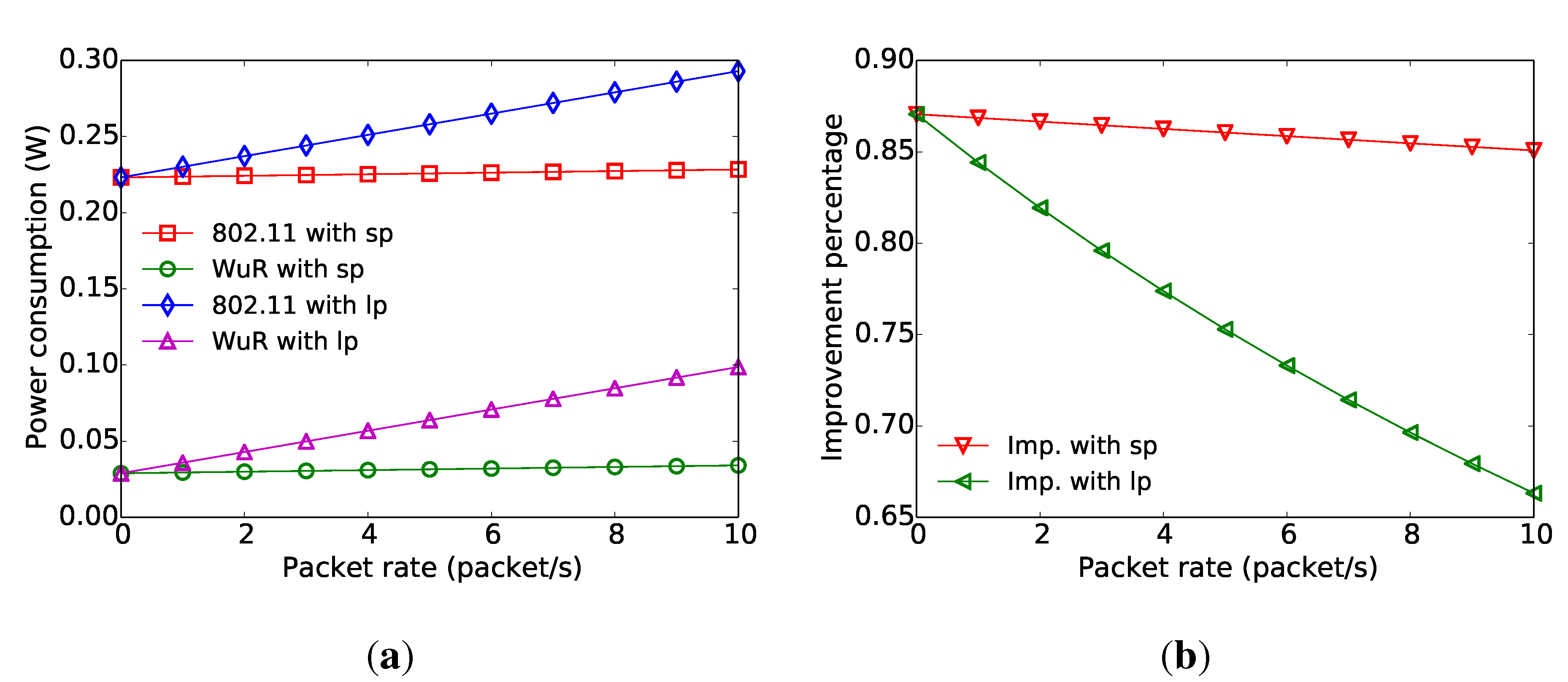
We observe that the packet rate affects the power consumption at a given beacon interval.
Figure 7a shows a relationship between power consumption and packet rate with short data packets (notated as sp) of 34 bytes and long data packets (notated as lp) of 2334 bytes, respectively. The beacon interval is 100 ms. The conventional MAC protocol (notated as 802.11) incurs a higher power consumption than our MAC protocol (notated as WuR), as the conventional MAC protocol has idle-listening on high-power Wi-Fi radio. Our MAC protocol takes advantage of our LDWuR to save listening power. The long data packet induces higher power consumption than the short data packet, as the high-power Wi-Fi radio transmits a longer data packet from the access point to the station.
Figure 7b shows a relationship between improvement and packet rate with short data packets and long data packets, respectively. In terms of a short data packet, the improvement percentage decreases slightly when the packet rate increases, as our MAC protocol has more wake-up signal activity before beacons and data packets. In terms of the long data packet, the improvement percentage decreases rapidly when the packet rate increases, as the high-power Wi-Fi radio deals with a long data packet that causes our MAC protocol’s power consumption to be closer to the conventional MAC protocol.
Figure 7.
Power consumption is a function of packet rate. (a) Power consumption versus packet rate; (b) improvement on power consumption versus packet rate.
Figure 7.
Power consumption is a function of packet rate. (a) Power consumption versus packet rate; (b) improvement on power consumption versus packet rate.
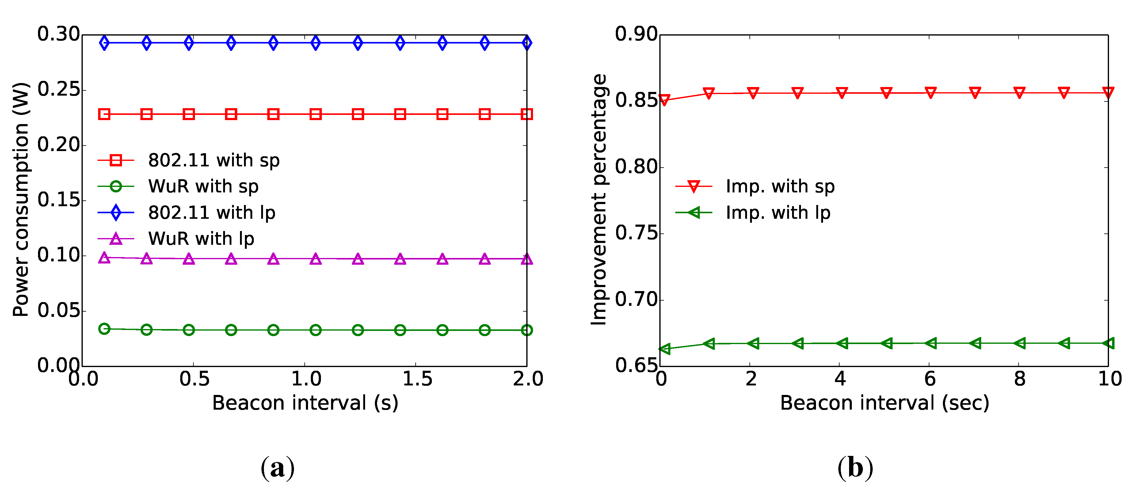
We explore the beacon interval impact on power consumption at a given packet rate. The packet rate is 10 packet/s.
Figure 8a shows that beacon interval affects power consumption. A small beacon interval has a slightly higher power consumption then a large beacon interval, as a small beacon interval has more beacon activity in a certain time period. Therefore, a small beacon interval has lower improvement in
Figure 8b. As the short data packet takes advantage of fewer activities on high-power Wi-Fi radio, it provides higher improvement than the longer data packet.
Figure 8.
Power consumption is a function of beacon interval. (a) Power consumption versus beacon interval; (b) improvement on power consumption versus beacon interval.
Figure 8.
Power consumption is a function of beacon interval. (a) Power consumption versus beacon interval; (b) improvement on power consumption versus beacon interval.
5.1.2. Latency
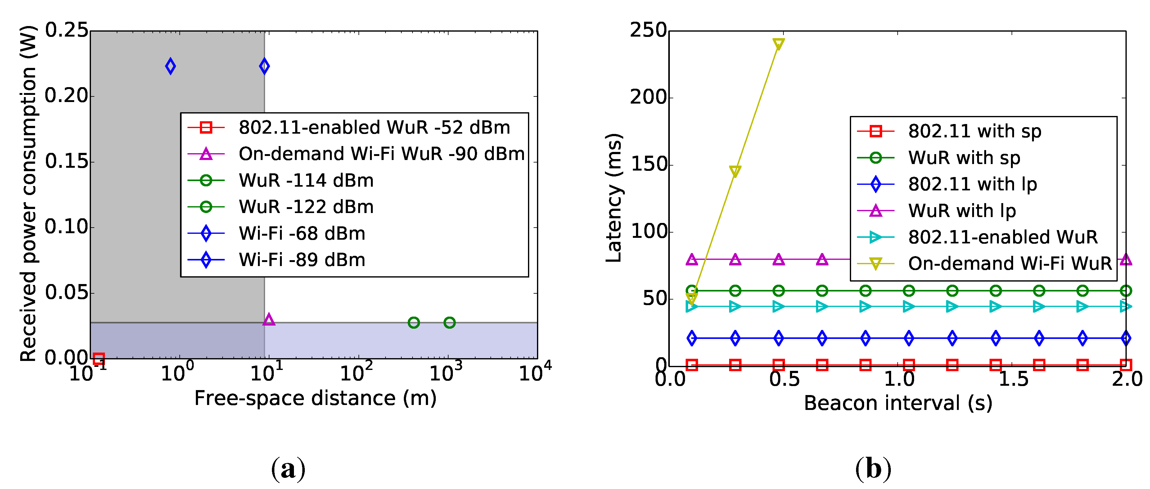
The latency comparison of our WuR with existing WuRs is shown in
Figure 9b. Our latencies depend on the expected transmission times of our wake-up radio and IEEE 802.11-compliant data radio that are computed by their PERs, respectively. In the simulation, we apply the empirical performance of our WuR from previous work [
24]. We adopt a receiver sensitivity of
dBm with a PER of 8% at 1 Mbps BPSK modulation of the D-Link DI-624 for IEEE 802.11-compliant data radio [
32]. Based on those PERs, we calculate their expected transmission times to estimate their latencies. Two radios induce more expected transmission time and increase latency. As our MAC protocol adopts our wake-up radio and IEEE 802.11-compliant data radio, our latency is longer than the conventional MAC protocol. In terms of the hardware performances of our WuR, they are described in previous work [
24]. We adopt our WuR as a basic module with directional and omnidirectional antennas for static and dynamicstrategies, respectively.
Figure 9.
Performance comparison of our LDWuR with existing WuRs. (a) Received power consumption versus free-space distance; (b) latency versus beacon interval.
Figure 9.
Performance comparison of our LDWuR with existing WuRs. (a) Received power consumption versus free-space distance; (b) latency versus beacon interval.
5.1.3. Performance Comparison
Figure 9a shows the comparison of our WuR with existing WuRs [
5,
20] in terms of received power consumption and free-space distance [
33]. To wake up the IEEE 802.11-compliant data radio, WuR is required to have a similar communication range as the IEEE 802.11-compliant radio. To save the IEEE 802.11-compliant radio’s power consumption, the required power consumption of WuR is lower than the IEEE 802.11-compliant radio. For the received power consumption, all WuRs’ power consumptions support sufficiently low power consumption. For the free-space distance, some WuRs support a sufficient communication range. Especially, our WuR performs with the best communication range among existing WuRs with the proper power consumption. The short-range WuR leads to a high-density deployment. This means that it requires more maintenance cost.
Figure 9b shows the latency comparison with existing WuRs [
5,
20] with various beacon intervals. Our WuR with sp has a similar latency as existing WuRs. As our design considers PERs and expected transmission times of our WuR and IEEE 802.11-compliant data radio, our WuR’s latency increases. However, existing WuRs do not consider the PER and expected transmission time. Thus, they have shorter latency than our WuR. As the latency of the work [
5] depends on the backoff time duration, we adopt the average latency of half a beacon interval to estimate it.
We adopt our WuR [
24] as a basic module with directional and omnidirectional antennas for static and dynamic strategies, respectively. The power consumption and latency of our basic module are described in the previous work [
24]. Our basic module’s total power consumption is the same as the average total power consumption of static and dynamic strategies. The latencies are
times and
times our basis module’s total latency for static and dynamic strategies, respectively.
In the performance evaluation section, the power consumptions in
Figure 7a and
Figure 8a include the power consumptions of our WuR. The power consumption of our WuR is 27.6 mW, while the listening power consumption of the IEEE 802.11-compliant radio is 223.2 mW [
31,
34]. We adopt the average total power consumption of static or dynamic antennas to evaluate performances. The probabilities of our WuR with packet error and the data radio with packet error are considered in Equation (
15). The false wake-ups or missed wake-ups are discussed in cases 1a and 1b, respectively [
24]. To compare the communication ranges of our WuR and IEEE 802.11-compliant radio, we adopt the sensitivity characteristic of our WuR and IEEE 802.11-compliant radio, as the communication range depends on the environments. Our WuR’s sensitivity is
dBm, while the IEEE 802.11-compliant radio’s sensitivity is
dBm for the IEEE 802.11b standard [
5]. In free space path loss conditions, our WuR performs a long-range communication of about 1 km, which is better than the IEEE 802.11b-compliant radio.
For the Wi-Fi data communication range of 802.11b (sensitivity level of
dBm) [
5], our WuR supports
dBm [
24], which is sufficient to cover the Wi-Fi data communication range. The existing study [
20] proposes a WuR with a sensitivity of
dBm. However, the sensitivity cannot cover the entire Wi-Fi data communication range, which limits the operational range.
6. Conclusions
We propose two strategies to search the transmitter’s direction to concentrate the receiver’s resources on the right location. This means that our LDWuR can improve the receiver’s cover range and power savings. We design the system model to analyze the power consumption and latency for our LDWuR. We also present our prototype and design concept. From the simulation results, we observe that our LDWuR and event-driven MAC protocol can repress the idle-listening power waste of Wi-Fi stations. Therefore, our design enhances the Wi-Fi power savings in wireless networks.


