Communication

Examination of Polymer Blends by AFM Phase Images

1
Faculty of Engineering Sciences and Mathematics, Bielefeld University of Applied Sciences, 33619 Bielefeld, Germany
2
Department of Physical and Biophysical Chemistry (PC III), Faculty of Chemistry, Bielefeld University, 33615 Bielefeld, Germany
*
Author to whom correspondence should be addressed.
Technologies 2023, 11(2), 56; https://doi.org/10.3390/technologies11020056
Submission received: 13 March 2023 / Revised: 29 March 2023 / Accepted: 10 April 2023 / Published: 12 April 2023
(This article belongs to the Topic Smart Manufacturing and Industry 5.0)

Abstract

:
Atomic force microscopy (AFM) belongs to the high-resolution surface morphology investigation methods. Since it can, in many cases, be applied in air, samples can more easily be inspected than by a scanning electron microscope (SEM). In addition, several special modes exist which enable examination of the mechanical and other physical parameters of the specimen, such as friction, adhesion between tip and sample, elastic modulus, etc. In tapping mode, e.g., phase imaging can be used to qualitatively distinguish between different materials on the surface. This is especially interesting for polymers, for which the evaluation by energy-dispersive X-ray spectroscopy (EDS) is mostly irrelevant. Here we give an overview of phase imaging experiments on different filaments used for 3D printing by fused deposition modeling (FDM). Furthermore, the acrylonitrile butadiene styrene (ABS), especially different poly(lactide acids) (PLAs) with special features, such as thermochromic or photochromic properties, are investigated and compared with SEM images.

1. Introduction

Atomic force microscopy (AFM) was developed in 1986 and has rapidly been developed further since, with new cantilevers, measuring modes and other improvements making faster and more exact measurements possible [1,2]. With AFM, single atoms can be depicted on perfectly flat surfaces, while measurements on biological samples still reach resolutions around 1 nm [3]. While other imaging methods, such as scanning electron microscopy (SEM) or transmission electron microscopy (TEM), reach similar resolutions, the AFM has the advantage of also enabling investigation of different mechanical and other physical properties of the sample surface. This is based on the AFM measurement principle in which a cantilever with a tip at its end is used to mechanically detect the sample surface [4]. The tip can have a radius typically around 1–20 nm and can either be moved along the sample surface (contact mode) or oscillate with the cantilever (tapping mode). For tips that are not further functionalized, very small forces around 10−11 and 10−7 N work on the tip [4]. The distance between the tip and sample surface is, for most modes, in the range of 0.1–10 nm. In the tapping mode, the oscillating cantilever can experience long-range attractive and short-range repulsive forces [5], which may increase or even delete the contrast and resolution, making it necessary to carefully choose the vibration amplitude in order to optimize these values [6,7,8].
This is not only valid for topography measurements but also for phase imaging which is often used in tapping mode. The phase, as well as the amplitude of the cantilever oscillation, highlight edges and, in this way, often show sharper images than the topography image [9]. On the other hand, the phase is additionally dependent on sample hardness, the elasticity of the surface and the adhesion between the sample surface and tip, allowing for differentiating between different materials at the surface by comparing which features are visible only in the phase, not in the topography [10]. It should be mentioned that for a quantitative evaluation, AFM can be combined with nanoscale infrared spectroscopy [11], while the AFM phase imaging mode enables qualitative differentiation between different phases.
This is especially interesting when polymer blends are developed, e.g., in the form of filaments for fused deposition modeling (FDM) or as photocurable resins for stereolithography (SLA). Generally, polymer blends can be used to optimize mechanical or other properties of polymers by combining different polymers, each of which adds its own advantages to the final blend [12,13,14]. Here we show AFM phase imaging results of different FDM printed layers, from acrylonitrile butadiene styrene (ABS) as a polymer with well-known phase separation to different poly(lactic acid) (PLA) blends containing thermochromic or photochromic materials and compare them with SEM images to evaluate which information can be received from both methods. Recently, only very few reports of AFM phase image investigations of 3D printed polymer blends are available in the literature, suggesting more investigations of such material blends [15,16,17].

2. Materials and Methods

As an example, for the differences between topography, amplitude and phase images, a polymer blend from polystyrene (PS) and a poly(styrene-butadiene-styrene) block-copolymer (SBS) is chosen, which is available in a toluene solution from Nanosurf (Liestal, Switzerland) and was dropped on a mica slide and is known to separate into two immiscible phases during evaporation of the solvent. The PS/SBS blend serves as a typical example of a blend in which the two phases are known to be well differentiable in AFM phase imaging.
One of the 3D printing filaments used in this study consists of ABS (Filamentworld, Neu-Ulm, Germany). ABS belongs to the high-impact composite materials which contain a particulate rubber (polybutadiene) phase in a polymer matrix (styrene-acrylonitrile copolymer, SAN), where the embedded rubber phase transfers the polymer into a ductile thermoplastic material [18]. Depending on the preparation process, different shapes and dimensions around 0.1–1.5 µm of the embedded rubber particles in the matrix can be expected [18].
Besides ABS, the following FDM printing filaments were investigated: HT-PLA (high-temperature poly(lactic acid)) (Filamentworld), PLA “UV” (photochromic filament from esun, Shenzhen, China), PLA “temp” (thermochromic filament from esun), PLA “color-change” (thermochromic filament “Z3D” from Zaper, Berlin, Germany) and PLA “sunlight change” (photochromic filament from TopZeal, China).
3D printing was performed with the FDM printer Orcabot XXL (Prodim, The Netherlands), nozzle diameter 0.4 mm, printing temperatures 215 °C (HT-PLA) or 210 °C (all other PLA samples), as well as with a CR-10 V2(Creality, Shenzhen, China), nozzle diameter 0.4 mm and printing temperature 230 °C (ABS).
AFM measurements were performed by a FlexAFM Axiom (Nanosurf) in tapping mode, using Tap190Al g cantilevers. The standard settings are setpoint 55%, P-gain 550, I-gain 1000, D-gain 100 and vibration amplitude 2 V.
Additional investigations of the material surfaces were performed by scanning electron microscopy (SEM, FEI XL30 ESEM, Philips, Amsterdam, The Netherlands) at a voltage of 13 kV after sputtering the samples with palladium.
The chemical investigation of the materials was performed by a Fourier-transform infrared (FTIR) spectrometer Excalibur 3100 (Varian Inc., Palo Alto, CA, USA) in attenuated total reflection mode (ATR-FTIR) in the wavenumber range from 4000–700 cm−1.

3. Results and Discussion

Firstly, Figure 1 depicts images of the PS–SBS blend taken with a relatively low magnification. According to the literature, the isles can be assumed to show the SBS phase, while PS establishes the matrix [19]. As mentioned before, the different polymers can only be distinguished qualitatively, not quantitatively, by the phase image (Figure 1c), meaning that it is not generally possible to evaluate a special mechanical property from the phase difference since the phase is based on a large amount of different physical properties. Some papers report that the darker phase areas (i.e., the smaller or more negative phase) show the softer material [20,21,22], while other studies show the opposite [10,23,24]. Here, SBS is a thermoplastic elastomer which is softer than the surrounding brittle PS matrix, so here the darker (smaller) phase corresponds to the harder material. It should be mentioned that the amplitude image (Figure 1b) highlights the edges so that this image looks much sharper than the topography image (Figure 1a), while real height differences are only visible in the topography image. Furthermore, especially the amplitude image shows some shadowing due to the scanning direction (from left to right), which is opposed in the image with an opposite scanning direction (not shown here); the minimum and maximum amplitudes and frequencies, however, are identical for both scanning directions.
Interestingly, there are also PS residues in the SBS isles visible at higher magnification, as Figure 2 shows. Here, the topography differences (Figure 2a) are much lower, while the phase image (Figure 2c) again shows clear differences, and the amplitude image (Figure 2b) shows a sharper image of the isles-in-isle distribution.
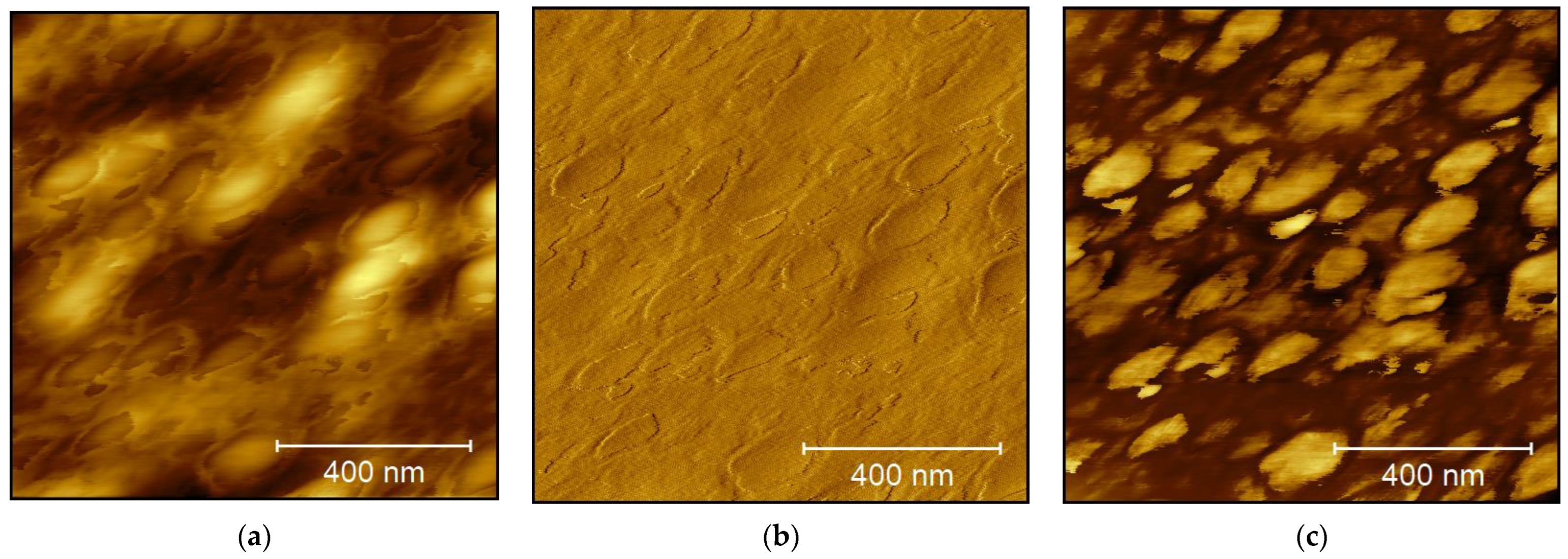
After this general test of the phase imaging technique, ABS was investigated as another sample whose composition is known. The results are depicted in Figure 3, here taken with an edge length of 1 µm, i.e., a higher resolution than in the previous images. While the very small height differences (the height range in Figure 3a is only 16 nm) are not very well visible, and the amplitude (Figure 3b) correspondingly does not show clear differences between isles and matrix, either, the amplitude again shows a strong contrast (here with a phase range of 90°), enabling distinguishing between two different polymers. As described in Section 2, ABS consists of a soft, rubbery polybutadiene phase embedded in a harder SAN matrix. Here again, the softer isles have the higher (brighter) phase. Nevertheless, as mentioned before, this correlation cannot be taken for granted for the next evaluations.
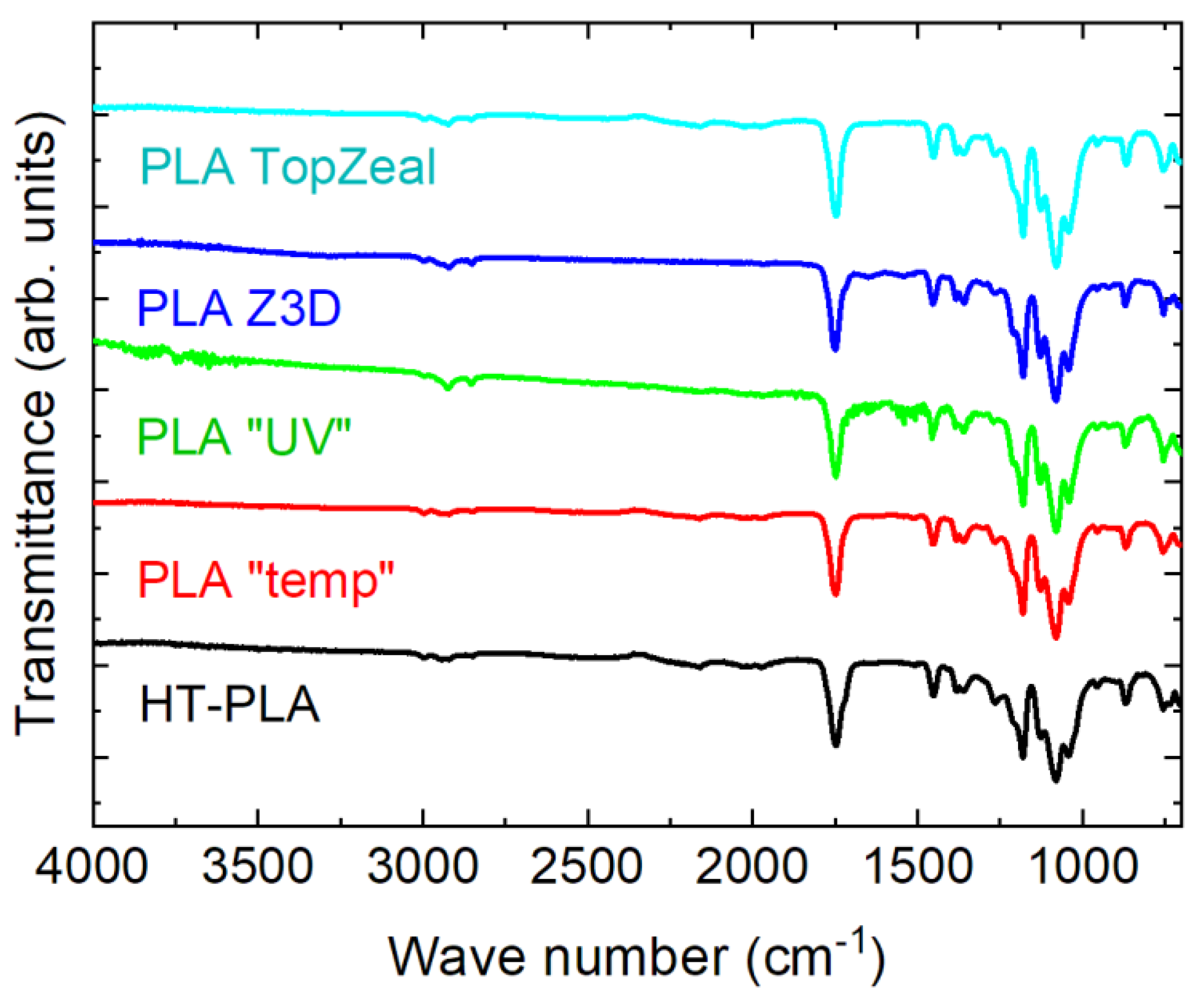
Next, the different PLA samples are investigated. To get an idea of their chemical composition, the results of the FTIR measurements are depicted in Figure 4. Generally, the following peaks can be expected for PLA: 2995 cm−1 (asymmetric –CH3 stretching vibration), 2946 cm−1 (symmetric –CH3 stretching vibration), 1746 cm−1 (C=O stretching vibration), 1452 cm−1 (asymmetric –CH3 bending vibration), 1361 cm−1 (symmetric –CH3 bending vibration) and 1080 cm−1 (C–O stretching vibration) [25,26,27,28]. While these peaks can be identified in Figure 4, no other peaks are visible, indicating a specific thermochromic or photochromic filler. No differences between the HT–PLA and the PLA blends are visible, indicating that other investigation methods are necessary to get an idea about the material blends used in this study.
AFM images of the HT–PLA samples are depicted in Figure 5. In addition, the deep crack on the left side of the display window, no strong differences in the amplitude or phase images are visible. The phase image does not show any details that are not visible in the other two images, suggesting a homogeneous polymer surface.
In the SEM image depicted in Figure 6, a rough structure with fine lines in a “vertical” direction is visible. The lines are oriented along the printing direction. Comparing this image with Figure 5, the crack visible in Figure 5a may be identical to these fine lines; however, SEM investigations with higher resolution were not performed since the effect of printing on the surface structure is not in the focus of this study.
To get an idea of the surface of the photochromic and thermochromic PLA materials, Figure 7 depicts SEM images of PLA “temp” and PLA “UV” as two examples of these filled PLA materials. For PLA “UV”, a relatively rough surface is visible (Figure 7a), which can be attributed to the printing process. The surface of the PLA “temp” here looks smoother (Figure 7b), but averaging over several SEM images, both materials have smoother and more fractioned positions. Interestingly, an inspection of the fracture surface (Figure 7c) of PLA “temp” reveals holes of diameters of several micrometers in which original microcapsules are located [29]. This is also visible for fracture surfaces of PLA “UV” [30]. However, no hints for different polymer phases are visible here, so that the SEM images suggest the material consists of thermochromic or photochromic microcapsules in pure PLA.
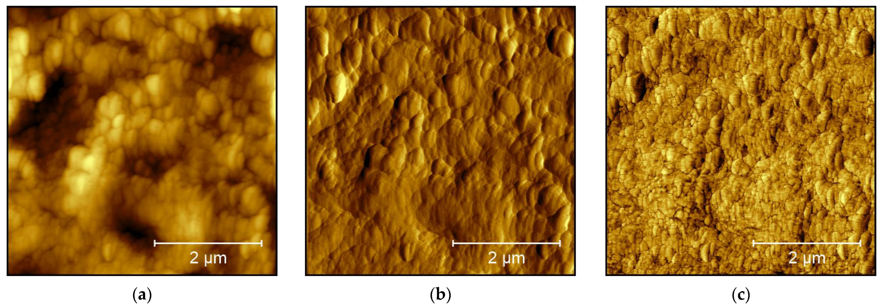
To investigate whether this interpretation is correct, AFM images of PLA “temp” are shown in Figure 8. It should be mentioned that the large microcapsules are not easily investigated by a contact method, such as AFM; thus, only the smooth printed surface was examined and not a fractured surface.
Generally, the phase image interpretation of such an irregular surface is more complicated than for the previously shown flat surfaces (Figure 1, Figure 2 and Figure 3). Nevertheless, comparing the phase image (Figure 8c) and amplitude image (Figure 8b) shows that there are no features exclusively visible in the phase image, indicating that no second polymer is visible here, i.e., that the thermochromic properties are reached by the microcapsules.
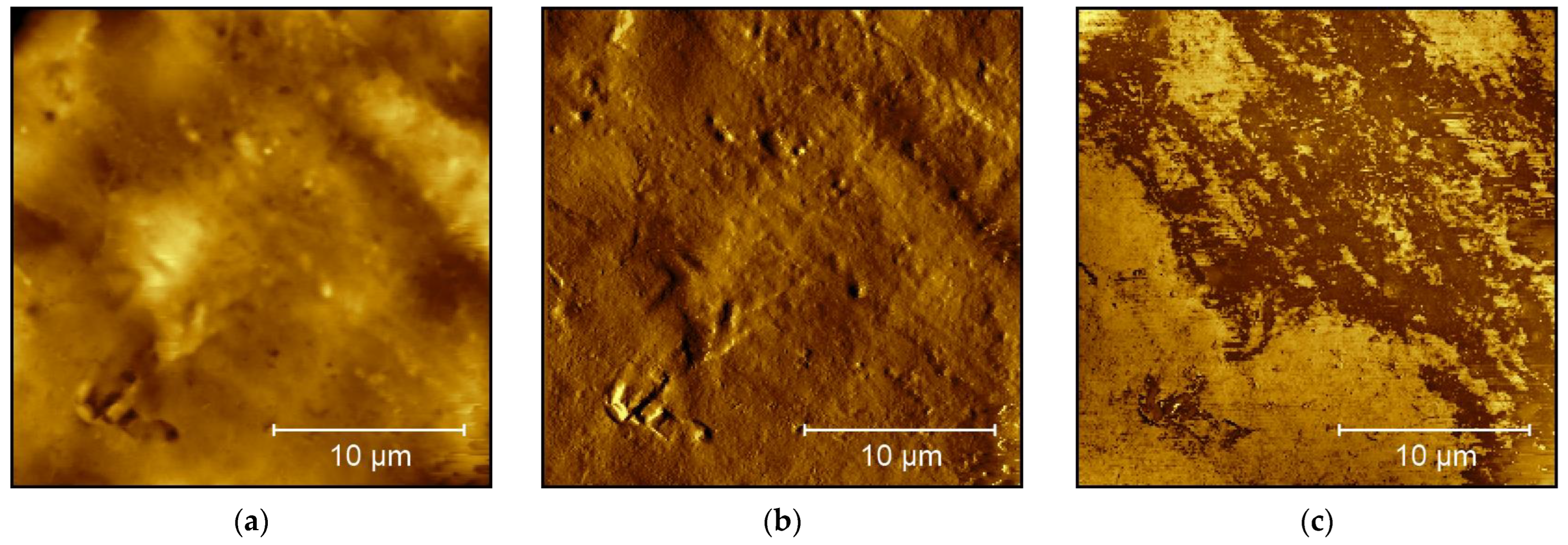
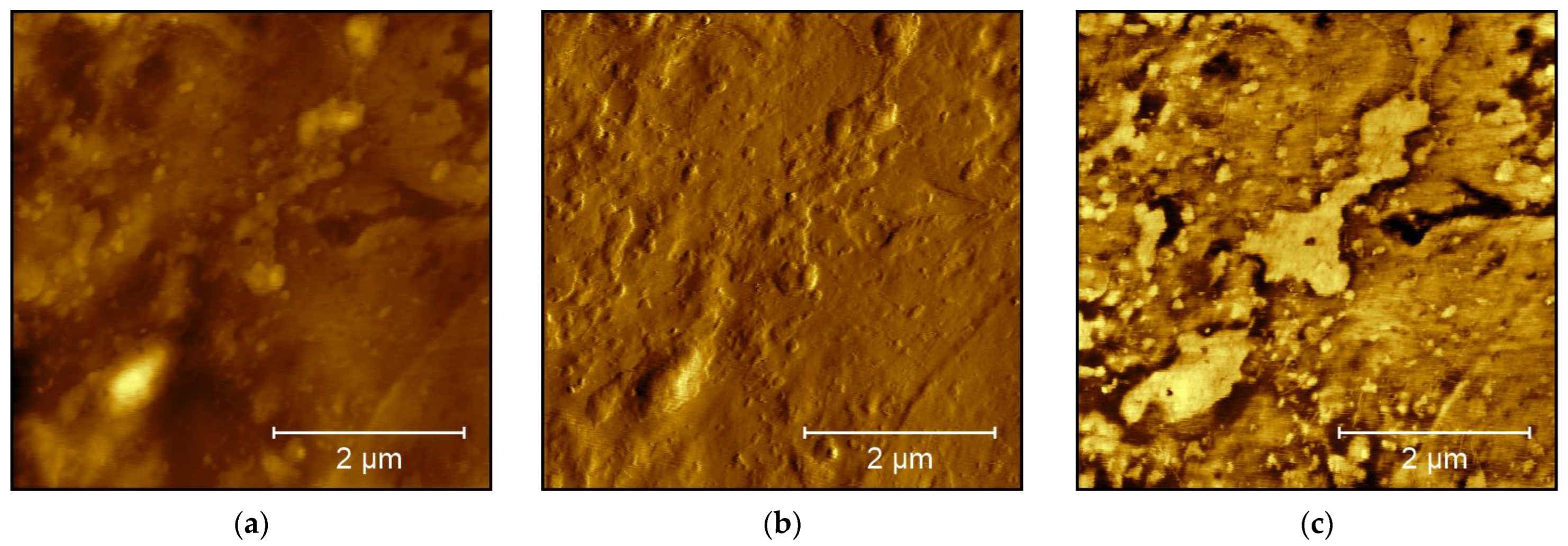
Unexpectedly, this is different for the filament PLA “UV” from the same producer, as shown in Figure 9. Here, strong phase differences are visible (Figure 9c), indicating either a polymer blend or an undesired contamination of the printed surface. Due to this finding, more AFM images were taken on both PLA “UV” and PLA “temp” (20 measurements per material with different image sizes from 2.5 µm to 50 µm). Outside the area depicted in Figure 9, no hints at a second phase were visible; all phase images looked similar to the one depicted in Figure 10c, while the surface topographies and the amplitudes also looked similar to Figure 8 (cf. Figure 10a,b). This more detailed examination suggests that although the printing nozzle was cleaned with cleaning filament when the filament material was changed, contamination is visible in Figure 9, and the thermochromic/photochromic effects of these two filaments are reached by the microcapsules depicted in Figure 7c.
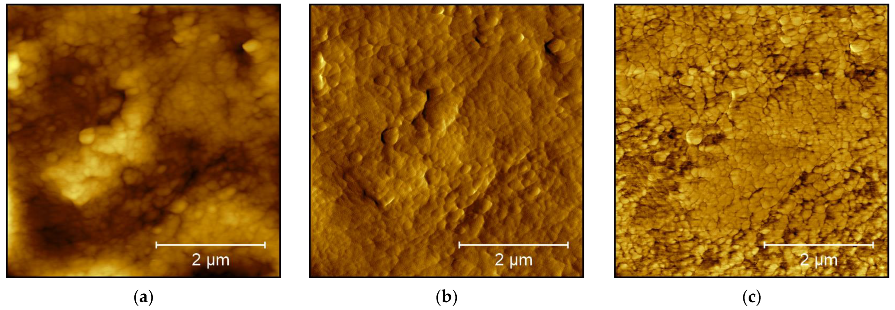
Next, the thermochromic filament Z3D is investigated by AFM. As Figure 11 shows, the surface structure looks different from the previous thermochromic and photochromic filaments, as visible in the topography (Figure 11a) and amplitude (Figure 11b). More interestingly, the phase image (Figure 11c) shows a clear phase separation. This finding was verified at 20 different sample positions to exclude the possibility that erroneous contamination was measured.
The large area of the second phase, verified by the other AFM images, is nevertheless unexpected since no second material was visible in the FTIR measurements (Figure 4), and the material should consist of PLA only, according to the material specifications from the producer. One possible explanation for this finding is that the phases visible in Figure 11c do not consist of two different polymers but of PLA with inorganic particles—which are usually not visible in the FTIR wavelength range used here—and without them. Suzuki et al. suggested using VO2-coated SiO2 nanoparticles in a PLA matrix to prepare a thermochromic nano composite and showed that the FTIR graphs depicted only PLA features [30]. Generally, such VO2/polymer nanocomposites are often used as nano thermochromic materials [31,32,33]. It can thus be assumed that VO2 or similar thermochromic nanoparticles [34] may be partly embedded in the PLA matrix of this material and show a slightly inhomogeneous distribution on the small scales investigated here, which does not translate into macroscopic inhomogeneities.
Finally, the photochromic filament from TopZeal is investigated. The results are depicted in Figure 12. Here again, two phases seem to be visible in the phase image (Figure 12c), although with much lower phase contrast than in the thermochromic Z3D sample (Figure 11c), while the surface topographies and amplitudes look quite similar. One of the typical photochromic nanomaterials is WO3 which can be embedded in polymers and does not modify their FTIR spectra in the usually examined wavelength range [35,36].
As these examples show, AFM phase imaging is a simple method to identify different polymer phases qualitatively, while additional techniques, such as X-ray photoelectron spectroscopy (XPS), Raman microscopy or infrared spectroscopy, are necessary to fully identify the different polymers [37,38,39]. Nevertheless, the general question of whether a material consists of a pure polymer or of a blend from two or more immiscible polymers can be answered by AFM phase imaging.

4. Conclusions and Outlook

FDM printed samples from ABS and filled/blended PLA as well as a PS/SBS blend were investigated by AFM phase imaging. While the PS/SBS blend shows a very high phase contrast of up to 137° between the SBS isles and the PS matrix, the 3D printed ABS sample had a clear phase contrast of 90° between the polybutadiene isles and the surrounding SAN matrix. HT–PLA had a very low phase contrast of only 12°, indicating a homogeneous polymer.
In two of the thermochromic/photochromic PLA filaments, relatively low phase contrasts of 16° and 26° were found, respectively, apparently resulting from the surface roughness visible in the topography images and the amplitude too. In these samples, SEM investigations found microcapsules which are apparently solely responsible for the color changes.
The other thermochromic and photochromic PLA filaments, however, showed higher phase contrasts of 43° and 77°, which were not correlated with surface roughness and allowed for identifying two different phases. Comparison with the FTIR results suggests that here inorganic nanoparticles are introduced in one of the phases, which are responsible for the color change effect.
This investigation shows that AFM phase imaging is a simple but powerful method to analyze whether a polymer is homogeneous or contains two or more phases.
In the future, comparing AFM phase images with Raman microscope images is planned for a large amount of polymer blends to enable a quantitative evaluation of the different phases and correspondingly figuring out why harder/softer phases are sometimes visible as darker, sometimes as brighter areas, i.e., show larger or smaller phase angles, and in which way other mechanical parameters of the polymers influence the phase angle. Ideally, for this purpose, a reference with a well-known phase angle should be defined so that not only blends but also pure polymers can be investigated to build up a large database on which the analysis regarding different mechanical properties can be performed.

Author Contributions

Conceptualization, E.W. and A.E.; methodology, E.W. and A.E.; formal analysis, E.W. and A.E.; investigation, E.W., B.B., U.G. and C.D.; writing—original draft preparation, A.E.; writing—review and editing, E.W., B.B., C.D. and U.G.; visualization, E.W. and A.E. All authors have read and agreed to the published version of the manuscript.

Funding

The study was partly funded by the German Federal Ministry for Economic Affairs and Climate Action via the AiF, based on a resolution of the German Bundestag, grant number KK5129708TA1. The APC was funded by Deutsche Forschungsgemeinschaft (DFG, German Research Foundation)–490988677–and Bielefeld University of Applied Sciences.

Institutional Review Board Statement

Not applicable.

Informed Consent Statement

Not applicable.

Data Availability Statement

Data are available from the corresponding author on reasonable request.

Conflicts of Interest

The authors declare no conflict of interest. The funders had no role in the design of the study, in the collection, analyses, or interpretation of data, in the writing of the manuscript or in the decision to publish the results.

References

  1. Binnig, G.; Quate, C.F.; Gerber, C. Atomic force microscope. Phys. Rev. Lett. 1986, 56, 930–933. [Google Scholar] [CrossRef]
  2. Parot, P.; Dufrene, Y.F.; Hinterdorfer, P.; Le Grimellec, C.; Navajas, D.; Pellequer, J.-L.; Scheuring, S. Past, present and future of atomic force microscopy in life sciences and medicine. J. Mol. Recognit. 2007, 20, 418–431. [Google Scholar] [CrossRef]
  3. Hoogenboom, B.W. Stretching the resolution limit of atomic force microscopy. Nat. Struct. Mol. Biol. 2021, 28, 629–630. [Google Scholar] [CrossRef] [PubMed]
  4. Jandt, K.D. Atomic force microscopy of biomaterials surfaces and interfaces. Surf. Sci. 2001, 491, 303–332. [Google Scholar] [CrossRef]
  5. García, R.; San Paulo, A. Amplitude curves and operating regimes in dynamic atomic force microscopy. Ultramicroscopy 2000, 82, 79–83. [Google Scholar] [CrossRef]
  6. Haugstad, G.; Jones, R.R. Mechanisms of dynamic force microscopy on polyvinyl alcohol: Region-specific non-contact and intermittent contact regimes. Ultramicroscopy 1999, 76, 77–86. [Google Scholar] [CrossRef]
  7. San Paulo, A.; García, R. High-resolution imaging of antibodies by tapping-mode atomic force microscopy: Attractive and repulsive tip-sample interaction regimes. Biophys. J. 2000, 78, 1599–1605. [Google Scholar] [CrossRef] [PubMed]
  8. Round, A.N.; Miles, M.J. Exploring the consequences of attractive and repulsive interaction regimes in tapping mode atomic force microscopy of DNA. Nanotechnology 2004, 15, S176–S183. [Google Scholar] [CrossRef]
  9. Joshi, J.; Homburg, S.V.; Ehrmann, A. Atomic force microscopy (AFM) on biopolymers and hydrogels for biotechnological applications—Possibilities and limits. Polymers 2022, 14, 1267. [Google Scholar] [CrossRef]
  10. Raghavan, D.; Gu, X.; Nguyen, T.; Van Landingham, M.; Karim, A. Mapping polymer heterogeneity using atomic force microscopy phase imaging and nanoscale indentation. Macromolecules 2000, 33, 2573–2583. [Google Scholar] [CrossRef]
  11. Dazzi, A.; Prater, C.B.; Hu, Q.C.; Chase, D.B.; Rabolt, J.F.; Marcott, C. AFM–IR: Combining Atomic Force Microscopy and Infrared Spectroscopy for Nanoscale Chemical Characterization. Appl. Spectrosc. 2012, 66, 1365–1384. [Google Scholar] [CrossRef]
  12. Atanase, L.I.; Lerch, J.-P.; Caprarescu, S.; Iurciuc (Tincu), C.E.; Riess, G. Micellization of pH-sensitive poly(butadiene)-block-poly(2 vinylpyridine)-block-poly(ethylene oxide) triblock copolymers: Complex formation with anionic surfactants. J. Appl. Polym. Sci. 2017, 134, 45313. [Google Scholar] [CrossRef]
  13. Ahmed, H.T.; Jalal, V.J.; Tahir, D.A.; Mohamad, A.H.; Abdullah, O.G. Effect of PEG as a plasticizer on the electrical and optical properties of polymer blend electrolyte MC-CH-LiBF4 based films. Results Phys. 2019, 15, 102735. [Google Scholar] [CrossRef]
  14. Caprarescu, S.; Radu, A.-L.; Purcar, V.; Sarbu, A.; Vaireanu, D.-I.; Ianchis, R.; Ghiurea, M. Removal of Copper Ions from Simulated Wastewaters Using Different Bicomponent Polymer Membranes. Water Air Soil Pollut. 2014, 225, 2079. [Google Scholar] [CrossRef]
  15. Cole, D.P.; Riddick, J.C.; Iftekhar Jaim, H.M.; Strawhecker, K.E.; Zander, N.E. Interfacial mechanical behavior of 3D printed ABS. J. Appl. Polym. Sci. 2016, 133, 43671. [Google Scholar] [CrossRef]
  16. León, A.S.; Domínguez-Calvo, A.; Molina, S.I. Materials with enhanced adhesive properties based on acrylonitrile-butadiene-styrene (ABS)/thermoplastic polyurethane (TPU) blends for fused filament fabrication (FFF). Mater. Des. 2019, 182, 108044. [Google Scholar] [CrossRef]
  17. Peng, B.G.; Yang, Y.C.; Ju, T.X.; Cavicchi, K.A. Fused Filament Fabrication 4D Printing of a Highly Extensible, Self-Healing, Shape Memory Elastomer Based on Thermoplastic Polymer Blends. ACS Appl. Mater. Interfaces 2021, 13, 12777–12788. [Google Scholar] [CrossRef]
  18. Moore, J.D. Acrylonitrile-butadiene-styrene (ABS)—A review. Composites 1973, 4, 118–130. [Google Scholar] [CrossRef]
  19. Ibrahim, B.A.; Kadum, K.M. Morphology studies and mechanical properties for PS/SBS blends. Int. J. Eng. Technol. 2012, 12, 19–27. [Google Scholar]
  20. Sauer, B.B.; McLean, R.S.; Thomas, R.R. Tapping Mode AFM Studies of Nano-Phases on Fluorine-Containing Polyester Coatings and Octadecyltrichlorosilane Monolayers. Langmuir 1998, 14, 3045. [Google Scholar] [CrossRef]
  21. Adhikari, R. Tapping mode atomic force microscopy (TMAFM) of some multi-component polymers. J. Nepal Chem. Soc. 2012, 29, 96–103. [Google Scholar] [CrossRef]
  22. Haviland, D.B.; van Eysden, C.A.; Forchheimer, D.; Platz, D.; Kassa, H.G.; Leclère, P. Probing viscoelastic response of soft material surfaces at the nanoscale. Soft Matter. 2016, 12, 619–624. [Google Scholar] [CrossRef]
  23. Leclère, P.; Lazzaroni, R.; Bredas, J.L.; Yu, J.M.; Dubois, P.; Jerome, R. Microdomain Morphology Analysis of Block Copolymers by Atomic Force Microscopy with Phase Detection Imaging. Langmuir 1996, 12, 4317. [Google Scholar] [CrossRef]
  24. McLean, R.S.; Sauer, B.B. Tapping-Mode AFM Studies Using Phase Detection for Resolution of Nanophases in Segmented Polyurethanes and Other Block Copolymers. Macromolecules 1997, 30, 8314. [Google Scholar] [CrossRef]
  25. Shankar, S.; Rhim, J.-W. Tocopherol-mediated synthesis of silver nanoparticles and preparation of antimicrobial PBAT/silver nanoparticles composite films. LWT-Food Sci. Technol. 2016, 72, 149–156. [Google Scholar] [CrossRef]
  26. Franca, D.C.; Almeida, T.G.; Abels, G.; Canedo, E.L.; Carvalho, L.H.; Wellen, R.M.R.; Haag, K.; Koschek, K. Tailoring PBAT/PLA/Babassu films for suitability of agriculture mulch application. J. Nat. Fibers 2019, 16, 933–943. [Google Scholar] [CrossRef]
  27. Siyamak, S.; Ibrahim, N.A.; Abdolmohammadi, S.; Yunus, W.M.Z.W.; Rahman, M.Z.A.B. Effect of fiber esterification on fundamental properties of oil palm empty fruit bunch fiber/poly(butylene adipate-co-terephthalate) biocomposites. Int. J. Mol. Sci. 2012, 13, 1327–1346. [Google Scholar] [CrossRef]
  28. Zhao, P.; Liu, W.Q.; Wu, Q.S.; Ren, J. Preparation, mechanical, and thermal properties of biodegradable polyesters/poly(lactic acid) blends. J. Nanomater. 2010, 2010, 287082. [Google Scholar] [CrossRef]
  29. Storck, J.L.; Ehrmann, G.; Güth, U.; Uthoff, J.; Homburg, S.V.; Blachowicz, T.; Ehrmann, A. Investigation of Low-Cost FDM-Printed Polymers for Elevated-Temperature Applications. Polymers 2022, 14, 2826. [Google Scholar] [CrossRef]
  30. Suzuki, H.; Yamaguchi, K.; Miyazaki, H. Fabrication of thermochromic composite using monodispersed VO2 coated SiO2 nanoparticles prepared by modified chemical solution deposition. Compos. Sci. Technol. 2007, 67, 3487–3490. [Google Scholar] [CrossRef]
  31. Maaza, M.; Nemraoui, O.; Sella, C.; Beye, A.C.; Baruch-Barak, B. Thermal induced tunability of surface plasmon resonance in Au–VO2 nano-photonics. Opt. Commun. 2005, 254, 188–195. [Google Scholar] [CrossRef]
  32. Zhou, H.J.; Cao, X.; Jiang, M.; Bao, S.H.; Jin, P. Surface plasmon resonance tunability in VO2/Au/VO2 thermochromic structure. Laser Photonics Rev. 2014, 8, 617–625. [Google Scholar] [CrossRef]
  33. Faucheu, J.; Bourgeat-Lami, E.; Prevot, V. A Review of Vanadium Dioxide as an Actor of Nanothermochromism: Challenges and Perspectives for Polymer Nanocomposites. Adv. Eng. Mater. 2019, 21, 1800438. [Google Scholar] [CrossRef]
  34. Garshasbi, S.; Santamouris, M. Using advanced thermochromic technologies in the built environment: Recent development and potential to decrease the energy consumption and fight urban overheating. Sol. Energy Mater. Sol. Cells 2019, 191, 21–32. [Google Scholar] [CrossRef]
  35. DeJournett, T.J.; Spicer, J.B. The influence of oxygen on the microstructural, optical and photochromic properties of polymer-matrix, tungsten-oxide nanocomposite films. Sol. Energy Mater. Sol. Cells 2014, 120, 102–108. [Google Scholar] [CrossRef]
  36. Ma, Q.; Yang, B.; Li, H.H.; Guo, J.J.; Zhao, S.Q.; Wu, G.H. Preparation and properties of photochromic regenerated silk fibroin/Tungsten trioxide nanoparticles hybrid fibers. Compos. Commun. 2021, 27, 100810. [Google Scholar] [CrossRef]
  37. Schmidt, U.; Hild, S.; Ibach, W.; Hollricher, O. Characterization of Thin Polymer Films on the Nanometer Scale with Confocal Raman AFM. Macromol. Symp. 2005, 230, 133–143. [Google Scholar] [CrossRef]
  38. Artyushkova, K.; Farrar, J.O.; Fulghum, J.E. Data fusion of XPS and AFM images for chemical phase identification in polymer blends. Surf. Interface Anal. 2009, 41, 119–126. [Google Scholar] [CrossRef]
  39. Zhong, Z.X.; Peng, L.; Zhang, N.; Su, J.X.; Ye, N.B.; Luo, Z.F.; Han, C.C.; Huang, X.B.; Su, Z.H. Miscibility of isotactic polypropylene with random and block ethylene-octene copolymers studied by atomic force microscopy-infrared. Polymer 2022, 259, 125354. [Google Scholar] [CrossRef]
Figure 1. Atomic force microscopy (AFM) images of a polystyrene/styrene-butadiene-styrene block-copolymer (PS/SBS) blend: (a) topography (height range 1.4 µm); (b) amplitude; (c) phase image (phase range 137°).
Technologies 11 00056 g001
Figure 2. AFM images of a polystyrene/styrene-butadiene-styrene block-copolymer (PS/SBS) blend with higher resolution: (a) topography (height range 1.0 µm); (b) amplitude; (c) phase image (phase range 55° without the black area which was not correctly measured).
Technologies 11 00056 g002
Figure 3. AFM images of a 3D printed acrylonitrile butadiene styrene (ABS) surface: (a) topography (height range 16 nm); (b) amplitude; (c) phase image (phase range 90°).
Technologies 11 00056 g003
Figure 4. Fourier transform infrared spectroscopy (FTIR) measurements of the different PLA filaments used in this study. The graphs are vertically shifted for clarity.
Technologies 11 00056 g004
Figure 5. AFM images of a 3D printed HT–PLA surface: (a) topography (height range 0.7 µm); (b) amplitude; (c) phase image (phase range 12° without the crack).
Technologies 11 00056 g005
Figure 6. Scanning electron microscopy (SEM) image of HT–PLA.
Technologies 11 00056 g006
Figure 7. SEM images of 3D printed materials: (a) surface of PLA “UV”; (b) surface of PLA “temp”; (c) fractured surface of PLA “temp”.
Technologies 11 00056 g007
Figure 8. AFM images of a 3D printed PLA “temp” surface: (a) topography (height range 154 nm); (b) amplitude; (c) phase image (phase range 16°).
Technologies 11 00056 g008
Figure 9. AFM images of a 3D printed PLA “UV” surface: (a) topography (height range 1.2 µm); (b) amplitude; (c) phase image (phase range 77°).
Technologies 11 00056 g009
Figure 10. AFM images of a 3D printed PLA “UV” surface, taken at another position: (a) topography (height range 265 nm); (b) amplitude; (c) phase image (phase range 26°).
Technologies 11 00056 g010
Figure 11. AFM images of a 3D printed Z3D surface: (a) topography (height range 174 nm); (b) amplitude; (c) phase image (phase range 77°).
Technologies 11 00056 g011
Figure 12. AFM images of a 3D printed TopZeal surface: (a) topography (height range 216 nm); (b) amplitude; (c) phase image (phase range 43°).
Technologies 11 00056 g012
Disclaimer/Publisher’s Note: The statements, opinions and data contained in all publications are solely those of the individual author(s) and contributor(s) and not of MDPI and/or the editor(s). MDPI and/or the editor(s) disclaim responsibility for any injury to people or property resulting from any ideas, methods, instructions or products referred to in the content.