Article

Enhanced Energy Transfer Efficiency for IoT-Enabled Cyber-Physical Systems in 6G Edge Networks with WPT-MIMO-NOMA

by
Agbon Ehime Ezekiel
1,
Kennedy Chinedu Okafor
2,3,*,
Sena Timothy Tersoo
1,
Christopher Akinyemi Alabi
4,
Jamiu Abdulsalam
5,
Agbotiname Lucky Imoize
6,
Olamide Jogunola
7 and
Kelvin Anoh
3
1
Department of Electronics and Telecommunications Engineering, Ahmadu Bello University, Zaria 810107, Nigeria
2
Department of Electrical and Electronic Engineering Science, University of Johannesburg, Johannesburg 2006, South Africa
3
School of Engineering, University of Chichester, Bognor Regis PO21 1HR, UK
4
Telecommunications Engineering Department, Air Force Institute of Technology (AFIT), Kaduna 800282, Nigeria
5
Department of Electrical Engineering and Computer Science, South Dakota School of Mines and Technology, Rapid City, SD 57701, USA
6
Department of Electrical and Electronics Engineering, Faculty of Engineering, University of Lagos, Akoka, Lagos 101017, Nigeria
7
Department of Computing and Mathematics, Manchester Metropolitan University, Manchester M15 6BH, UK
*
Author to whom correspondence should be addressed.
Technologies 2024, 12(8), 119; https://doi.org/10.3390/technologies12080119
Submission received: 4 May 2024 / Revised: 22 June 2024 / Accepted: 17 July 2024 / Published: 24 July 2024
(This article belongs to the Topic Cyber-Physical Security for IoT Systems)

Abstract

:
The integration of wireless power transfer (WPT) with massive multiple-input multiple-output (MIMO) non-orthogonal multiple access (NOMA) networks can provide operational capabilities to energy-constrained Internet of Things (IoT) devices in cyber-physical systems such as smart autonomous vehicles. However, during downlink WPT, co-channel interference (CCI) can limit the energy efficiency (EE) gains in such systems. This paper proposes a user equipment (UE)–base station (BS) connection model to assign each UE to a single BS for WPT to mitigate CCI. An energy-efficient resource allocation scheme is developed that integrates the UE–BS connection approach with joint optimization of power control, time allocation, antenna selection, and subcarrier assignment. The proposed scheme improves EE by 24.72% and 33.76% under perfect and imperfect CSI conditions, respectively, compared to a benchmark scheme without UE–BS connections. The scheme requires fewer BS antennas to maximize EE and the distributed algorithm exhibits fast convergence. Furthermore, UE–BS connections’ impact on EE provided significant gains. Dedicated links improve EE by 24.72% (perfect CSI) and 33.76% (imperfect CSI) over standard connections. Imperfect CSI reduces EE, with the proposed scheme outperforming by 6.97% to 12.75% across error rates. More antennas enhance EE, with improvements of up to 123.12% (conventional MIMO) and 38.14% (massive MIMO) over standard setups. Larger convergence parameters improve convergence, achieving EE gains of 7.09% to 11.31% over the baseline with different convergence rates. The findings validate the effectiveness of the proposed techniques in improving WPT efficiency and EE in wireless-powered MIMO–NOMA networks.

1. Introduction

The emerging IoT era has led to explosive growth in the number of connected devices. To support the massive machine-type communications in IoT networks, the next generation (5G and beyond) wireless networks need to provide higher data rates and expanded coverage. The abundant device connectivity also necessitates energy-efficient communication techniques to reduce the carbon footprint [1,2]. Technologies such as MIMO [3] and NOMA [4] have arisen as two promising technologies to meet these critical requirements. Massive MIMO employs a large number of antennas to provide substantial improvements in spectral efficiency and energy efficiency [5]. NOMA allows multiple users to share the same time–frequency resources via power domain multiplexing and successive interference cancellation, improving user connectivity and bandwidth utilization. The combination of massive MIMO and NOMA, referred to as massive MIMO–NOMA, can unlock further performance gains in future wireless networks [6]. However, providing continuous and reliable communication to massive IoT devices with limited power and storage capabilities remains an important challenge. For IoT devices, WPT has emerged as a viable solution that allows wireless charging of energy-constrained nodes over the air interface [7].
By enabling wireless-powered communication networks (WPCN), the base stations can wirelessly charge the IoT devices via WPT in the downlink and receive data from them in the uplink [8]. The integration of WPT with massive MIMO–NOMA networks can therefore realize self-sustaining IoT systems with perpetual operation capabilities. Nevertheless, co-channel interference (CCI), inherent in the WPT phase in such networks, can limit the energy efficiency (EE) gains. CCI occurs in this type of network when the IoT user equipment (UE), especially cell-edge users, receives signals for WPT from multiple base stations or moves across cells during the WPT phase. The resulting interference impedes efficient wireless charging, thereby degrading the EE performance of WPT-enabled massive MIMO–NOMA networks.
Prior works have developed resource allocation algorithms focusing on transmit power, time allocation, antennas, etc., to improve the EE of wireless-powered massive MIMO–NOMA networks. [9] conducted a study on energy-efficient resource allocation in Machine-to-Machine (M2M) communications for the IoT. The work proposed joint power control and time allocation techniques for minimizing energy consumption while considering circuit power. The results showed that NOMA consumed less total energy than time division multiple access (TDMA) at a low circuit power, but that TDMA achieved better network EE at a high circuit power. Authors in [7] investigated the performance of NOMA schemes in WPCN, with a specific emphasis on system EE. The work considered a scenario with multiple energy-harvesting UEs that operate using a harvest-then-transmit protocol. The study observed that broadcasting at higher power levels was more energy-efficient for WPCN with uplink NOMA and the exponential decay quality of service (QoS) parameter had a significant impact on the optimal solution. Another study [10] developed an energy-efficient resource allocation scheme in massive MIMO–NOMA networks with wireless power transfer, using a distributed alternating direction method of the multipliers (ADMM) approach. The study suggested a novel joint power, time, antenna, and subcarrier resource allocation strategy that can efficiently control the time required for energy harvesting and data transmission in order to maximize the EE of the network. In [11], a fairness-aware resource allocation scheme (FA-RAS) for a WPCN utilizing multiple sources for WPT was proposed. The study addressed the joint optimization of power and block-length allocation to improve the reliability of short packet transmissions. The proposed scheme showed the potential to enhance EE and system performance.
However, these works do not address the CCI issue arising from WPT, which is pivotal in ensuring effective IoT UE charging and high EE. The work [12] proposed a scheme for collecting Interference Signal (IS) energy during intense CCI in a cellular network. The system has the advantage of saving network energy during interference periods after which transmission takes place. The work recorded throughput and energy enhancement. However, results from the study showed that the presence of inherent interference mitigated the performance of the network, resulting in delays. The authors [13] examined a two-way relaying non-orthogonal multiple access IoT network whereby two NOMA users communicate through an IoT access point relay using a decode-and-forward protocol. The study further included CCI analysis for practicality. However, the outage probability of the network was limited due to the presence of interference in NOMA. The papers [14,15] proposed a multiuser non-cooperative computation offloading game to optimize offloading probabilities, incorporating factors like the vehicle-Multiaccess Edge Computing (MEC) distance and multivehicle competition. Results from the work showed fast convergence of the MEC algorithm. However, the MEC server suffered from interference, which resulted in reduced expected performance. The work [16] considered the effect of platoon vehicles’ air-to-ground and ground-to-air communication to solve the problem of poor communication for road traffic-based BSs. Simulation results showed improved power and data transmission. However, the interference between the set platoon vehicles affected the expected performance of the platoon network. The authors [17] proposed a multi-edge-IoT system that sets a new standard for efficiency within the IoT ecosystem, outperforming existing approaches in key metrics such as energy consumption, latency, communication overhead, and packet loss rate. Despite the significant contribution, the interference from the IoT devices mitigated the performance of the designed system.
Authors [18,19,20,21] proposed wireless-powered mobile edge computing schemes to improve the performance of wireless networks in terms of resource allocation and energy efficiency. Results recorded an improvement in the general performance of the network. However, during WPT, the network suffered from high interferences between network devices.
In this present study, the key contributions are as follows:
  • This work proposes a UE–BS connection model to assign each UE to a single BS for WPT in order to mitigate CCI during the wireless charging phase;
  • This study developed an energy-efficient resource allocation scheme that integrates the UE–BS connection approach with joint optimization of transmit power, time allocation, antenna selection, and subcarrier assignment;
  • This work derived a non-convex mixed integer optimization problem for EE maximization and applied some techniques such as relaxation and approximation to transform it into a more tractable form;
  • The study further applied the Alternating Direction Method of Multipliers (ADMM) to efficiently solve the resource allocation problem in a distributed manner.
The remaining parts of the paper are organized as follows. Section 2 provides background on massive MIMO–NOMA, WPT, and CCI. Section 3 describes the proposed UE–BS connection model. Section 4 presents the energy-efficient resource allocation scheme. Section 5 evaluates the performance of the proposed scheme via simulations. Finally, Section 6 concludes the paper.

2. Related Works

This section provides an overview of the key technologies and concepts that form the foundation for this work—massive MIMO–NOMA networks, wireless power transfer, and CCI in WPT.

2.1. Massive MIMO–NOMA Networks

Massive MIMO involves deploying a large number of antennas at the base station (BS) to provide substantial improvements in spectral efficiency, coverage, and radiated energy efficiency (EE). The large antenna array offers higher spatial degrees of freedom to simultaneously serve multiple users in the same time–frequency resource. In particular, massive MIMO exploits the channel hardening effect, where the channel vectors become nearly deterministic as the number of antennas grows large. Channel hardening arises from the law of large numbers, where the channel gains between each antenna and the user becomes increasingly orthogonal. This results in reduced multi-user interference and minimal intra-cell interference [22]. With channel hardening, simple matched filter precoders and combiners that require only large-scale fading CSI tend to optimal performance [23]. Consequently, massive MIMO systems can approach theoretical capacity limits with low-complexity signal processing. Furthermore, the array gain improves the received signal power, allowing for large reductions in transmit power. Massive MIMO networks therefore offer substantial improvements in spectral efficiency and energy efficiency compared to conventional MIMO systems [24]. NOMA allows multiple access on the same resource block, where users are multiplexed in the power domain at different power levels [25]. On the transmitter side, superposition coding is applied to send a sum of messages to the NOMA users [2]. The receivers exploit the power disparity through successive interference cancellation (SIC), where multi-user interference is decoded and removed successively, starting from the highest power message. NOMA provides higher bandwidth utilization compared to orthogonal multiple access techniques like OFDMA [26]. The non-orthogonal transmissions and SIC decoding also aid in lowering latency. Therefore, NOMA enhances connectivity, capacity, and user fairness in multi-user networks [6].
The combination of massive MIMO and NOMA unlocks further performance benefits compared to either technique alone. In massive MIMO–NOMA networks, the BS is equipped with antennas denoted by M to serve single-antenna users denoted by K on the same time–frequency resources, i.e., M >> K. For the downlink, the base station applies beamforming to transmit the superposition-coded signals to the NOMA users. At the receiver side, SIC is applied to remove multi-user interference. For the uplink, the base station leverages the large array gain to detect the NOMA user signals using low-complexity linear receivers. With proper design, massive MIMO–NOMA networks can greatly improve system performance and EE [27].

2.2. Wireless Power Transfer

Wireless power transfer (WPT) is a technology that shows potential for remotely providing energy to devices with low power consumption. These devices may have small rechargeable batteries or no built-in power source at all [28]. This eliminates the need for battery replacement or wired charging of devices like sensors and IoT nodes, which have limited battery storage. WPT typically utilizes electromagnetic waves or radio signals and hence its effectiveness is contingent upon the characteristics of the wireless connection and the design of the receiving circuitry. WPT can broadly be categorized into near-field and far-field techniques [29].
Near-field WPT exploits non-radiative magnetic or electric fields using inductive coupling or magnetic/electric resonance between the transmit and receive coils. However, the range is limited to the coil diameter, requiring accurate alignment between the transmitter and receiver. Far-field or RF-based WPT utilizes radiative electromagnetic waves, providing greater mobility and allowing wireless charging of multiple devices simultaneously [22]. Omnidirectional transmission as well as narrowband beamforming can be applied for efficient wireless power delivery over longer distances. Ambient RF signals from TV, cellular, and Wi-Fi transmissions can also be harvested as a source of WPT. The key enablers for far-field WPT include [30].
  • Directional beamforming techniques like maximum ratio transmission focus the radiated wireless energy toward the energy harvester’s location;
  • Waveform and transmit optimization to maximize the DC power extracted by the energy harvester circuitry;
  • Sensitive antenna designs and low-power electronics to improve the RF-to-DC conversion efficiency.
The integration of massive MIMO–NOMA with WPT is particularly promising since the large array gain can significantly enhance the efficiency and range of RF wireless power transfer [30]. However, co-channel interference (CCI) arising from the broadcast nature of WPT transmission can limit the energy efficiency benefits. Effective interference management techniques are necessary to facilitate efficient wireless power delivery in WPT-enabled wireless communication networks.

2.3. Co-Channel Interference in WPT

A major impediment in realizing the full benefits of WPT is the problem of CCI during the WPT phase [31]. CCI arises when multiple base stations concurrently transmit wireless power to a user in the same frequency band. This unwanted co-channel interference power reduces the RF-to-DC conversion efficiency, leading to a loss in the usable harvested energy. CCI is particularly detrimental for cell edge users that lie in the intersection of multiple cells [32]. The interfering signals received from neighboring base stations can be of similar or even higher strength than the intended signal. This greatly impedes the efficient wireless charging of edge users. Studies from the works of [15,16] have further shown that CCI is a major problem that has limited the performance of most wireless devices in terms of energy efficiency and throughput.

3. Proposed UE–BS Connection Model
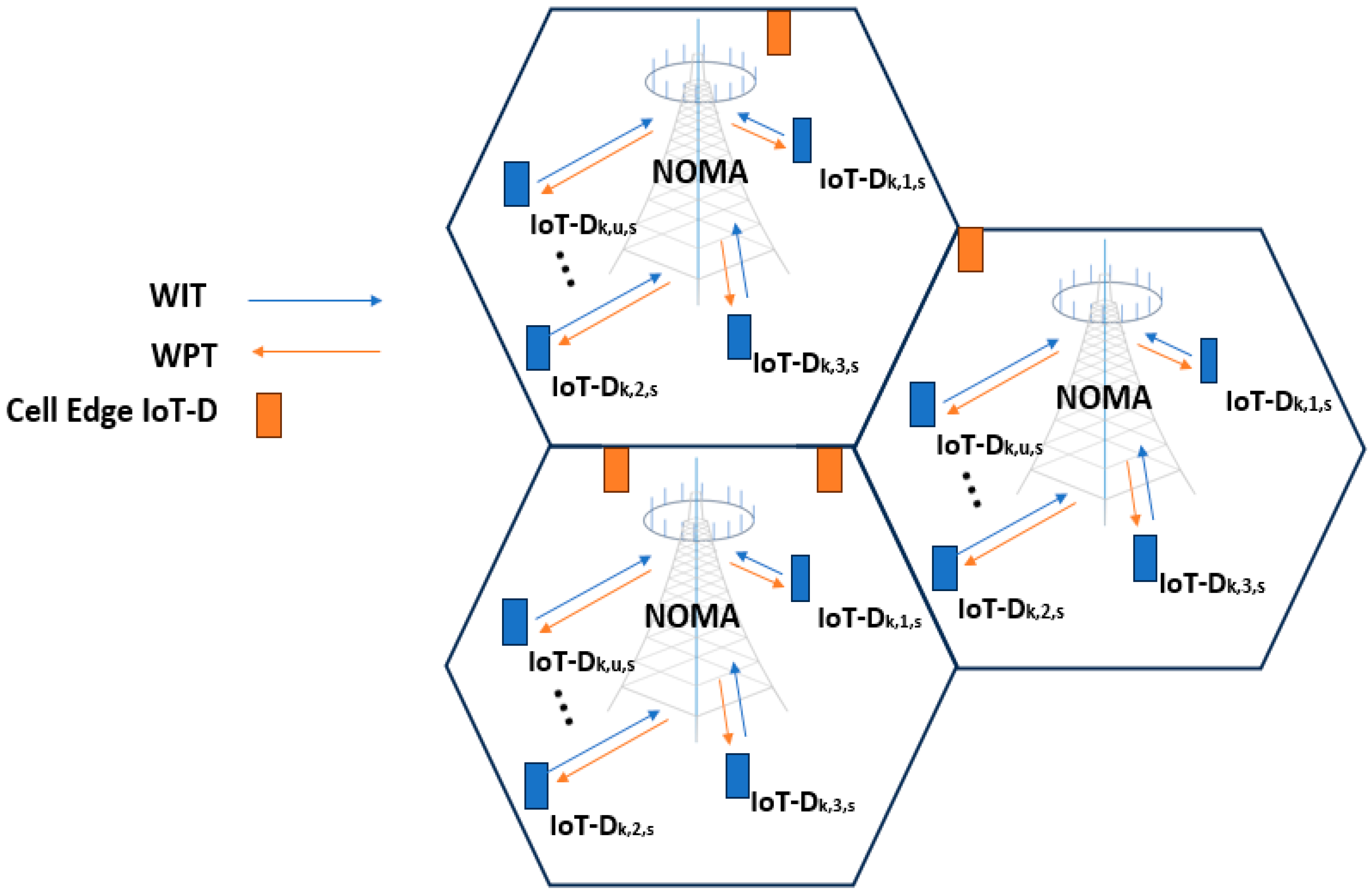
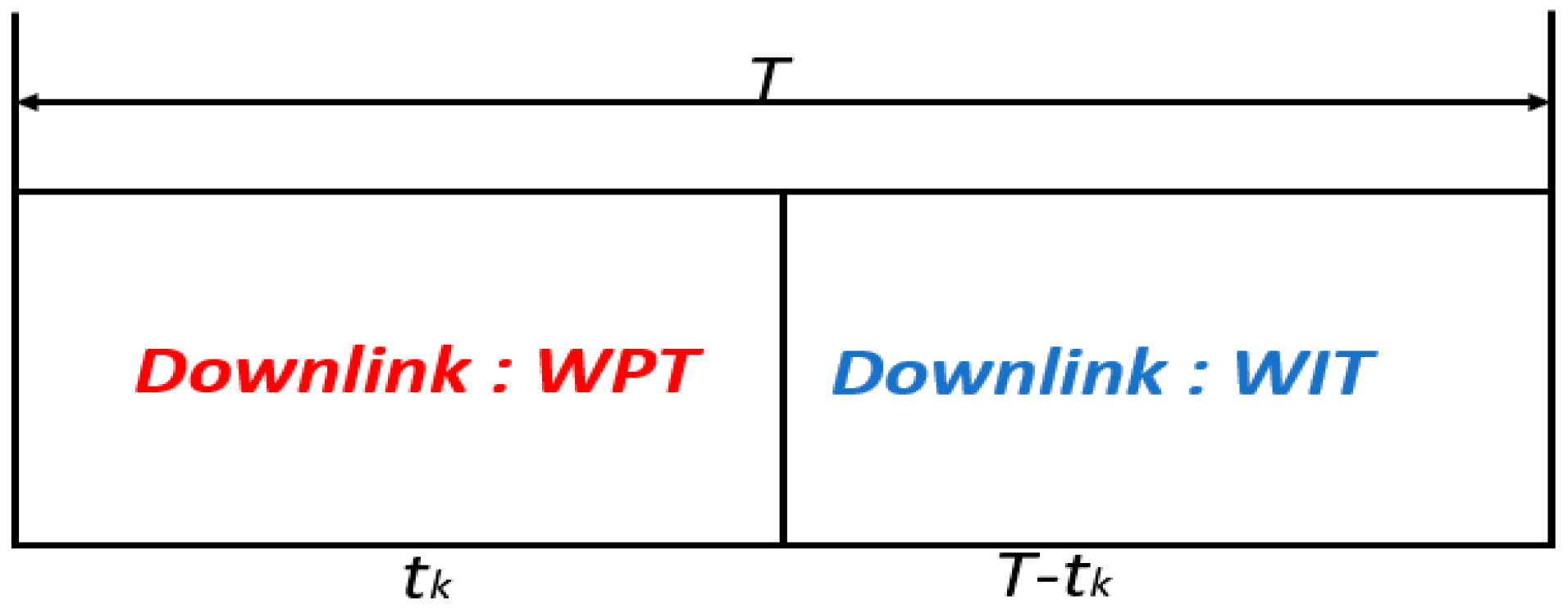
The following is a discussion of the proposed UE base station model used in this study.

3.1. System Model

We consider a distributed multicell WPT-enabled massive MIMO–NOMA network with a large number of battery-powered IoT devices. There are K cells. Every cell has a BS located at the cell center and several rechargeable IoT devices that are randomly scattered within the cell. The BS in the k-th cell (i.e., BSk and k ∈ K) and has multiple antennas; each IoT device is with a single antenna as shown in Figure 1.
The BSk broadcasts a deterministic signal, denoted by W k with power over the downlink channel to power the nearby UE; a set of subcarriers are given in Equations (1) and (2) [7].
P = W k 2
S = 1,2 , . . s .
The total system bandwidth is B and the subcarrier bandwidth is Bs s S . The subcarrier bandwidth is denoted in Equation (10) [10].
B s = B S .
The IoT device allocated to subcarrier s in the k-th k K cell is represented as u u U . Each BS is equipped with a Channel Estimator (CE) that is used to estimate the characteristics of the channel. The candidate number of the antenna set is denoted by M, while N represents the selected set of antenna vectors for all cells. Here, Mk represents the maximum number of antennas for the BSk and Nk,s represents the optimal number vector of antennas picked in the k-th cell on subcarrier s. Nk,u,s denotes the ideal number of antennas for a given situation. By selecting the best antenna for each BS, it can be inferred that Nk,n may be simplified to Nk [10].
The system operates in a harvest-then-transmit time slot protocol. Each communication time block T is divided into two slots—a downlink WPT time slot of duration tk followed by an uplink Wireless Information Transfer (WIT) time slot of duration T-tk, as illustrated in Figure 2. During the WPT time slot, the BSs broadcast wireless energy, which is harvested by the IoT devices. In the WIT time slot, the IoT devices transmit their independent messages to the BS using the harvested energy.
To mitigate CCI during WPT, each IoT device has to be associated with a single BS for wireless charging in a given communication time block.

3.2. UE–BS Connection Matrix

We define a UE–BS connection variable as X u , k to indicate the association between UEs and BSs for wireless power transfer. In the situation whereby D k , u , s I o T is connected with BSk, X u , k assumes a value of 1; otherwise, it assumes a value of 0. We denote this mathematically as shown in Equation (4).
X u , k = 1 , I f   u t h   D I o T   i s   c o n n e c t e d   t o   k t h   B S 0 , O t h e r w i s e . .
Each UE D k , u , s I o T can only connect to one BS for WPT in a given communication time block to reduce CCI. So, the connection matrix between the u-th and k-th BS is obtained as shown in Equation (5).
X = x 1,1 x 1,2 x 1 , K x 2,1 x 2,2 x 2 , K x I o T D , 1 x I o T D   2 x I o T D ,   K .
During WPT, the u-th D k , u , s I o T can have access to a certain number of antennas of k-th BS simultaneously. Hence, we model the connection between the u-th D k , u , s I o T to the k-th BS with the following constraint as given in Equation (6).
k = 1 K X u , k B S k .
where B S k is the total number of accessible BSs in K number of cells in the network.
Furthermore, we define the connection indication matrix Z between the u-th D k , u , s I o T and M antennas in Equation (7).
  Z = Z u , k , M D k , u , s I o T × K × M .
where M and K denotes the candidate antenna number and number of BS.
That is, if the m-th antenna of the k-th BS is allocated to its connected u-th UE then the connection indication variable Z u , k , M assumes a value of 1 otherwise it assumes a value of 0. We express this in Equation (8).
z { u , m } ( k ) = 1 , i f   a n t e n a   m B S k   a l l o c a t i o n   t o   u t h - U E   w i t h   B S k 0 , o t h e r w i s e
The connection variable of the u-th D k , u , s I o T and k-th BS becomes that shown in Equation (9).
Z = Z u , M k T                          k = 1,2 , . K .
where T is a single communication time block.
Intuitively, each UE should connect to the BS, which provides the highest channel gain for efficient wireless charging. However, jointly optimizing X u , k with other resource allocation policies leads to a complex mixed integer programming problem. The UE–BS connection model is described in Algorithm 1. The algorithm takes the network parameters and channel gains as the input. It initializes the connection matrices, selects antennas based on channel gain, and establishes dedicated UE–BS connections while limiting each UE to connect to only one BS.
Algorithm 1: UE–BS Connection Model
 1: Input: K, U, M, h, and N
 2: Output: x
 3: Initialize UE–BS connection matrix x to zeros
 4: Estimate channel gains hk,u,s
 5: Select optimal antennas Nk,u,s based on channel gains
 6: Initialize antenna connection matrix Zk,u,s
 7: for u = 1 to U do
 8:        for k = 1 to K do
 9:        for m = 1 to M do
10:        if Nk,u,s = m then
11:        Zk,u,s = 1
12:        else
13:        Zk,u,s = 0
14:        end if
15:        end for
16:        end for
17: end for
18: Establish UE–BS connections:
19: for u = 1 to U do
20:        k* = arg maxk(Zu,k,1:M)
21:        xu,k* = 1
22: end for
23: Limit each UE to 1 BS:
24: for u = 1 to U do
25:        if  (xu,1:K) > 1 then
26:        k = arg maxk(Zu,k,1:M)
27:        xu,k = 1
28:        xu,1:K\k = 0
29:        end if
30: end for
31: return x

4. Energy-Efficient Resource Allocation Scheme

The following sub-section discusses the EE resource allocation scheme used in the course of this study.

4.1. Problem Formulation

The objective is to maximize the system EE of the considered massive MIMO–NOMA network integrated with WPT. We formulate an optimization problem that jointly optimizes the transmit power, time, antenna, subcarrier allocation, and the UE–BS connection to maximize the system EE. The energy beamforming approach is applied for WPT to improve the power transfer efficiency. The energy transmitter (i.e., the BS), under the assumption of perfect CSI, has a downlink received signal at D k , u , s I o T on subcarrier s, as given in Equation (10) [10].
y k , u , s P = α k , u b k , u , s H h k , u , s Z k + n k , u , s
where h k , u , s is the downlink channel gain vector between B S k and D k , u , s I o T , b k , u , s H is the energy beamforming vector, α k , u denotes the coefficient of path loss, n k , u , s represents the Additive White Gaussian Noise (AWGN), and Ë k stands for the energy signal transmitted by B S k .
The transmit power of B S k , which is another form of Equation (1), is expressed as [10], as follows:
E Ë K 2 = P k .
So, the harvested energy of D k , u , s I o T from the energy transmitter according to the law of energy conservation during WPT is obtained in Equation (12) [23].
E k , u , s = η t k α k , u 2 b k , u , s H h k , u , s 2 P k                        η 0 η 1 .
where η is the conversion efficiency from the RF power source to electrical energy.
In the WIT time slot (Ttk), D k , u , s I o T sends information to B S k using the energy that has been harvested. The uplink NOMA transmission technique is applied to complete the message transmission. To complete the message transmission, the uplink NOMA transmission technique is utilized. A set decoding order for the received signals follows when multi-user detection and SIC are implemented at the B S k . The uplink received signal is expressed in Equation (13).
y k , u , s P = E k , u , s T t k α k , u h k , u , s H x k , u , s + n ¯ k , u , s + Γ k , u , s .
where n ¯ k , u , s denotes the AWGN in the WIT uplink phase, Γ k , u , s denotes the co-channel interference under perfect CSI condition, and X k , u , s denotes the transmitted signal from D k , u , s I o T through the power-domain NOMA denoted by E k , u , s T t k .
The Signal-to-Interference-Plus-Noise Ratio (SINR) of D k , u , s I o T on the subcarrier s is formulated as given in Equation (14) [10].
Υ k , u , s P = E k , u , s α k , u 2 h k , u , s 2 I i n t r a , k + I i n t e r , k + σ 2 .
where σ 2 is variance in white Gaussians noise and I i n t r a , k and I i n t e r , k denote the intra-cell and the inter-cell co-channel interferences.
The above formulations are for perfect CSI considerations. However, in realistic massive MIMO–NOMA communication networks, the errors in channel estimation, feedback, and quantization result in imperfect CSI at the transmitters, degrading the system EE. We consider a quasi-static Rayleigh channel, where the channel between B S k and D k , u , s I o T remains constant for each time block T and changes independently between different time blocks. In each block, B S k employs the CE to estimate the channel by the Minimum Mean Square Error (MMSE) approach. The estimated channel is expressed in Equation (15) [33,34]:
h ^ k , u , s = h k , u , s e k , u , s .
where e k , u , s is the channel estimation error.
The process of EH involves the use of the energy beamforming policy given as b ^ k , u , s . Considering the beamforming method and imperfect CSI, the system modifies the energy transfer direction, such that the IoT devices capture as much energy as possible. The energy signal of D k , u , s I o T received in the WPT is then expressed in Equation (16) [10].
y k , u , s i m   P = α k , u b ^ k , u , s h k , u , s Z k + n k , u , s .
The same as shown in the perfect CSI instance, the harvested energy by D k , u , s I o T under imperfect CSI knowledge is given by Equation (17) [10].
E k , u , s = η t k α k , u 2 b k , u , s H h k , u , s 2 P k .
The process of acquiring CSI knowledge obtained from the known training pilot signals, which are broadcast at regular intervals, is important as it ensures that complete and precise signal detection and decoding in the uplink are carried out. Once the superimposed signals of the IoT devices are received by the BS, several signal processing steps are performed to acquire the desired signal of each IoT device.
In wireless communication systems, user EE is quantified as the number of bits of information reliably delivered to a receiver per unit of energy consumed at the transmitter. When there are multiple users, it is also important to consider system EE. Furthermore, this allows for resource allocation in such a way that overall energy usage becomes more efficient. This motivation leads to consideration of system EE, which is generally defined by [7] in Equation (18).
E n e r g y   E f f i c i e n c y = T o t a l   T h r o u g h p u t t o t a l   C o n s u m e d   E n e r g y b / J
To maximize the EE of a massive MIMO–NOMA network, it is necessary to achieve near-optimal throughput performance while operating at lower power consumption levels. So, according to the Shannon capacity formula and channel hardening characteristic of massive MIMO–NOMA networks at the s-th subcarrier, the data rate from D k , u , s I o T to BSk is shown by Equation (19):
R k , u , s = B s l o g 2 1 + l n M k N k , u , s y k , u , s N k , u , s
where y k , u , s = N k , u , s in the condition of perfect CSI and y k , u , s = y k , u , s i m   P in the condition of imperfect CSI. Therefore, the EE from D k , u , s I o T to B S k subcarrier s is denoted in Equation (20).
η E E ( k , u , s ) = R k , u , s E k , u , s .
The total throughput of massive MIMO NOMA is then expressed in Equation (21) [10].
R t o t P , t , N , C , x = k = 1 K u = 1 U s = 1 S c k , u , s T t k R k , u , s         P P 1 ,   P 2 , , P k ,     t t 1 ,   t 2 , , t k ,     C c k , u , s ,     N N k , u , s ,    X x k , u , s
where P, t, N, C, and x are the vectors of transmit power, time, selected antenna, subcarrier allocation, and UE–BS connection policies, respectively.
The total consumed energy by the system is given in Equation (22) [10].
E t o t P , t N , C x = k = 1 K P b s m a x x u , k N k , u , s + U P u s e r T + s = 1 S P k c k , u , s t k .
where Pbs and Puser are the power consumptions of each antenna at BSk and each IoT device, respectively.
Thus, the EE of the considered massive MIMO–NOMA networks can be calculated in Equation (23).
R t o t a l P , t , N , C , x = R t o t a l P , t , N , C , x E t o t a l P , t , N , C , x .
Also, Q 1 , which is the EE maximization model (having seven constraints C) using the proposed UE–BS connection, is expressed in Equation (24).
Q 1 :    m a x P , t , N , C , x η E E P , t , N , C , x .
s . t     C 1 :   0 P k P b s , m a x ,         k K
C 2 :   0 t k T m a x ,         k K
   C 3 : 0 E k , u , s T t k P u s e r , m a x ,         k K ,     u U ,     s S
   C 4 : R k , u , s P u s e r , m a x ,         k K ,     u U ,     s S
    C 5 : N k , u , s 1,2 , . M k          k K ,     u U ,     s S
C 6 : c k , u , s 0 ,   1 ,      u = 1 U c k , u , s U .          k K ,     u U ,     s S
  C 6 : c k , u , s 0 ,   1 ,      u = 1 U c k , u , s U .          k K ,     u U ,     s S  
where constraint C 1 ensures that the maximum transmit power of BSk does not exceed P b s , m a x , constraint C 2 specifies the time range for energy transfer, C 3 makes sure that the transmit power of D k , u , s I o T is non-negative and does not exceed P u s e r , m a x , C 4 ensures thta the channel rate of D k , u , s I o T does not fall below the minimal rate R m i n , C 5 ensures that the active antennas allocated for each IoT device offer fairness among IoT devices and save the RF cost, C 6 ensures that the allocation of the subcarrier is carried out, and one subcarrier can be multiplexed by at most U IoT devices and C 7 ensures that u-th D k , u , s I o T is connected to the k-th BS.
This problem is non-convex and combinatorial. In the next subsection, we present an efficient optimization approach based on relaxation and successive convex approximation to find high-quality solutions.

4.2. Non-Linear Optimization

The formulated EE maximization problem Q1 is non-convex due to the fractional objective function and coupled optimization variables. To tackle this, we apply the dual domain decomposition method to convert the fractional problem into an equivalent subtractive linear form as seen in Equation (25).
Q 2 :   m a x P , t , N , C , x R t o t P , t , N , C , x η E E E t o t P , t , N , C , x .
s . t     C 1 :   0 P k P b s , m a x ,         k K .
C 2 :   0 t k T m a x ,         k K .
   C 3 : 0 E k , u , s T t k P u s e r , m a x ,         k K ,     u U ,     s S .
   C 4 : R k , u , s R m i n ,         k K ,     u U ,     s S .
    C 5 : N k , u , s 1,2 , . M k          k K ,     u U ,     s S .
    C 6 : c k , u , s 0 ,   1 ,      u = 1 U c k , u , s U .          k K ,     u U ,     s S .
   C 7 : x u , k 1 ,   2 ,   , B S k   ,      k = 1 K x u , k B S k .          k K ,     u U ,     s S .
With respect to Q 2 , there is a non-zero duality gap between the primal problem and dual problem. To solve this problem, constraints C 5 and C 6 were relaxed to continuous values. Thus, C 5 and C 6 was replaced by N k , u , s and c k , u , s . Q 3 can be transformed into Q 3 , as shown in Equation (26):
Q 3 :   m a x P , t , N , C , x R t o t P , t , N , C , x η E E E t o t P , t , N , C , x .
s . t     C 1 :   0 P k P b s , m a x ,         k K .
C 2 :   0 t k T m a x ,         k K .
   C 3 : 0 E k , u , s T t k P u s e r , m a x ,         k K ,     u U ,     s S .
   C 4 : R k , u , s R m i n ,         k K ,     u U ,     s S .
    C 5 : N k , u , s 1,2 , . M k          k K ,     u U ,     s S .
    C 6 : c k , u , s 0 ,   1 ,      u = 1 U c k , u , s U .          k K ,     u U ,     s S .   
   C 7 : x u , k 1 ,   2 ,   , B S k   ,      k = 1 K x u , k B S k .          k K ,     u U ,     s S .
The principle of strong duality theory guarantees that the asymptotically optimal solution for Q 3 may be obtained, according to the optimal solution offered by the dual domain. The allocation strategy of resource allocation can be optimized by solving Q 3 in an iterative manner. By running such an iterative process, the optimal solution for resource allocation and η E E can be obtained. The proposed energy-efficient resource allocation scheme is implemented through the iterative algorithm outlined in Algorithm 2 where the key steps for jointly optimizing the resources and UE–BS connections are provided.
Algorithm 2: Energy Efficient Resource Allocation Scheme.
Input: K, U, M, S, h, X, Pmax, Pbs, Puser, T, Rmin, Pbs,max, Puser,max, αk,u, and ηEE
Output: x, P, t, N, and C
1. Initialize x, P, t, N, and C
2. Calculate channel rates Rk,u,s based on h, P, and N
3. while not converged do
4.     Update X to optimize UE–BS connections
5.     Update P to maximize EE under Pmax constraint
6.     Update t to allocate WPT and WIT time
7.     Update N for optimal antenna selection
8.     Update C for subcarrier assignment
9.     Calculate UE rates Rk,u,s based on current P, t, N, and C
10. end while
return x, P, t, N, and C
The algorithm takes the network parameters, channel gains, and connections as the input. It iteratively optimizes the power, time, antenna selection, and subcarrier allocation to maximize EE while satisfying QoS constraints. The output is the optimized resource allocation policies.

4.3. Distributed ADMM Approach

We propose a distributed solution based on the ADMM to solve the EE maximization problem. ADMM allows decomposing the original problem into smaller subproblems that can be solved in parallel [35]. The relaxed problem is still non-convex due to the objective function. To apply ADMM, we introduce local copies of the optimization variables at each BS, as shown in Equations (27)–(29).
t ^ k = t k
n ^ k , u , s = N k , u , s
c ^ k , u , s = c k , u , s
The global consensus problem with the local variable copies is given as Q 4 and it is shown in Equation (30).
Q 4 :   m a x P , t , N , C , x P , t ~ , N ~ , C ~ , x ~ .
s . t       C ~ 1 :   0 P k P b s , m a x ,         k K .
C ~ 2 :   0 t ~ k T m a x ,         k K .
   C ~ 3 : 0 E k , u , s T t ~ k P u s e r , m a x ,         k K ,     u U ,     s S .
   C ~ 4 : R ~ k , u , s R m i n ,         k K ,     u U ,     s S .
    C ~ 5 : N ~ k , u , s 1,2 , . M k          k K ,     u U ,     s S .
    C ~ 6 : c ~ k , u , s 0 ,   1 ,      u = 1 U c ~ k , u , s U .          k K ,     u U ,     s S .
   C ~ 7 : x ~ u , k 1 ,   2 ,   , B S k   ,      k = 1 K x ~ u , k B S k .          k K ,     u U ,     s S .
Q 4 , the global consensus problem, is then transformed to Q5, as shown in Equation (31).
Q 5 :   m a x P , t , N , C , x P , t ^ , N ^ , C ^ , x ^ .
s . t     C ^ 1 :   P ^ k = P k ,         1 k K .
The ADMM framework splits this global problem into local subproblems at each BS by forming the augmented Lagrangian, as given by Equation (32).
ς P ¯ k ,   t ¯ k , n ¯ k , u , s , c ¯ k , u , s , x ¯ k , u , s ,   λ k = k = 1 K g k P ¯ k ,   t ¯ k , n ¯ k , u , s , c ¯ k , u , s , x ¯ k , u , s + k = 1 K λ k P ¯ k P k
The resource allocation variables are updated in an iterative fashion by solving the local subproblems in parallel and then by coordination to reach a consensus on the global solution. To maintain a uniform interference level and consistent EE, each BS updates the global variables at the beginning of an iteration. Following that, each BS handles the self-subproblems P , t ^ , N ^ , C ^ , x ^ on its own. The Lagrange multipliers are then updated at the BSs by gathering and using the local CSI of IoT devices. After achieving local convergence, the BSs trade power and IoT UE and BS connection values with one another in order to find the best option and modify the local resource allocation in the ensuing cycle. There is less signaling overhead when such an interactive and iterative method is used. There is no requirement for the BSs and IoT devices to exchange CSIs. Additionally, a large problem is divided up into a number of distributed little problems. This may then be resolved simultaneously, increasing the effectiveness of addressing the optimization problem [36]. Key steps in the distributed optimization approach are outlined in Algorithm 3.
Algorithm 3: Energy-Efficient Resource Allocation with Distributed ADMM
1:         Objective: Maximize system energy efficiency (EE)
2:         Input:
3:                 Local CSI:
4:                             hk—Local channel gain matrix at BS k
5:                             Nk—Local antenna selection at BS k
6:                             Rk—Local UE rate matrix at BS k
7:         Resource constraints:
8:              Pmax, tmin, tmax, Rmin, and Cmax—Local max connections per subcarrier
9:         1. Initialization:
10:             Initialize local copies of optimization variables at each BS k and local dual variables
11:             xk = 0
12:             Pk = Pmax/K
13:             tk = T/2
14:             Nk = M/K
15:             Ck = S/K
16:            λ ˜ k = 0 // For consensus on global UE–BS connections x
17:            μ ˜ k = 0 // For consensus on global power allocation P
18:            v ˜ k = 0 // For consensus on global energy efficiency EE
19:         2. Repeat until convergence:
20:         3. Each BS k updates local variables to maximize local EE
21:                    xk = arg max EE(xk, Pk, tk, Nk, and Ck)  s.t. local constraints
22:                    Pk = arg max EE(xk, Pk, tk, Nk, and Ck)
23:                    tk = arg max EE(xk, Pk, tk, Nk, and Ck)
24:                    Nk = arg max EE(xk, Pk, tk, Nk, and Ck)
25:                    Ck = arg max EE(xk, Pk, tk, Nk, and Ck)
26:         4. Update local dual variables
27:          λ ˜ k = λ ˜ k + ρΔ λ ˜
28:                μ ˜ k  =  μ ˜ k + ρΔ μ ˜ v ˜ k
29:              v ˜ k   = v ˜ k + ρΔ v ˜
30:         5. Exchange updates with neighbors
31:         Share xk, Pk, λ ˜ k ,   μ ˜ k , and v ˜ k
32:         6. Master node reaches consensus
33:          x = k t x k / K
34:          P = k t P k / K
35:         7. Broadcast consensus to BSs
36:                    Send xk, Pk to all BSs
37:         8. Until convergence criteria met
38:         return Optimized x, P, t, N, and C

Overview of the Computational Complexity of Distributed ADMM

Carrying out the computational complexity analysis of the distributed ADMM scheme over the existing scheme from the work [10] is very important to analyze the performance of both systems [37,38]. Table 1 provides a comprehensive comparison between the two scenarios, emphasizing the advantages of Scenario 2 (mEE-RAS) over Scenario 1 (EE-RAS). It highlights the improvements in co-channel interference mitigation, energy efficiency, and joint optimization achieved through the integration of the UE–BS connection model.
It can be observed that the mEE-RAS has the following advantages [38]:
  • Mitigates co-channel interference during the wireless charging phase;
  • Introduces an energy-efficient resource allocation scheme;
  • Integrates the UE–BS connection model for joint optimization;
  • Addresses additional constraints related to UE–BS connections (C7).
From Table 1, it is noteworthy that the mEE-RAS scheme introduces additional features and constraints compared to EE-RAS. But these do not significantly increase the overall computational complexity. The use of a distributed algorithm (D-ADMM) and the potential for parallelism ensure that the additional complexity remains manageable, resulting in approximately the same complexity for both schemes.

5. Performance Evaluation

5.1. Simulation Setup

In this subsection, we evaluate the performance of the proposed energy-efficient resource allocation scheme with the UE–BS connection model for WPT-based massive MIMO–NOMA networks (denoted as mEE-RAS), using numerical simulations. The simulation parameters used are presented in Table 2.
We average the results over random UE locations and channel realizations. The resource allocation problems are solved using standard nonlinear solvers in MATLAB. The distributed ADMM algorithm is implemented based on the consensus optimization framework in [36,37,38]. Such algorithm reduces computational complexities at the network edges [39].

5.2. Results and Discussion

In this section, we evaluate the performance of the proposed mEE-RAS and compare it with a benchmark scheme from the work of [10] without UE–BS connections. We use “EE-RAS” to denote the benchmark scheme without UE–BS connections [10]. The impact on system EE is analyzed under different network configurations. The EE-RAS optimizes the transmit power, time, antenna, and subcarrier allocation variables but does not explicitly optimize the UE–BS connections. The proposed scheme additionally optimizes the continuous UE–BS connection variables x u , k along with the resource allocation variables.
We simulate a multicell massive MIMO–NOMA network based on the parameters described in Section 5.1. We average the results over multiple channel realizations to evaluate the performance gains.
Key aspects analyzed through simulations:
  • Impact of UE–BS connection on system EE;
  • Performance under imperfect CSI;
  • Trends with the number of BS antennas;
  • Convergence of the distributed ADMM algorithm.
The results demonstrate the effectiveness of the proposed UE–BS connection model in providing significant EE gains across diverse network scenarios. Next, we discuss the key observations from the simulation results.

5.2.1. UE–BS Connection and EE

First, we evaluate the impact of the proposed UE–BS connection model on the system EE. Figure 3 compares the EE achieved by the proposed mEE-RAS with optimized UE–BS connections against the EE-RAS under both perfect and imperfect CSI through NOMA. It is observed that establishing dedicated UE–BS connections provides significant EE gains. By mitigating CCI during WPT, more useful energy can be harvested by the UEs. This additional harvested energy translates to higher UE transmit powers and data rates, thereby improving the system EE. From Figure 4, mEE-RAS achieved an EE improvement of 24.72% over the EE-RAS, having an average EE value of 4.23 × 10−4 bits/J/Hz in the case of perfect CSI. In the case of imperfect CSI, mEE-RAS achieved an EE improvement of 33.76%, having an EE value of 3.12 × 10−4 bits/J/Hz. The results demonstrate that explicitly optimizing the UE–BS connections is highly beneficial in improving WPT efficiency and the system EE.

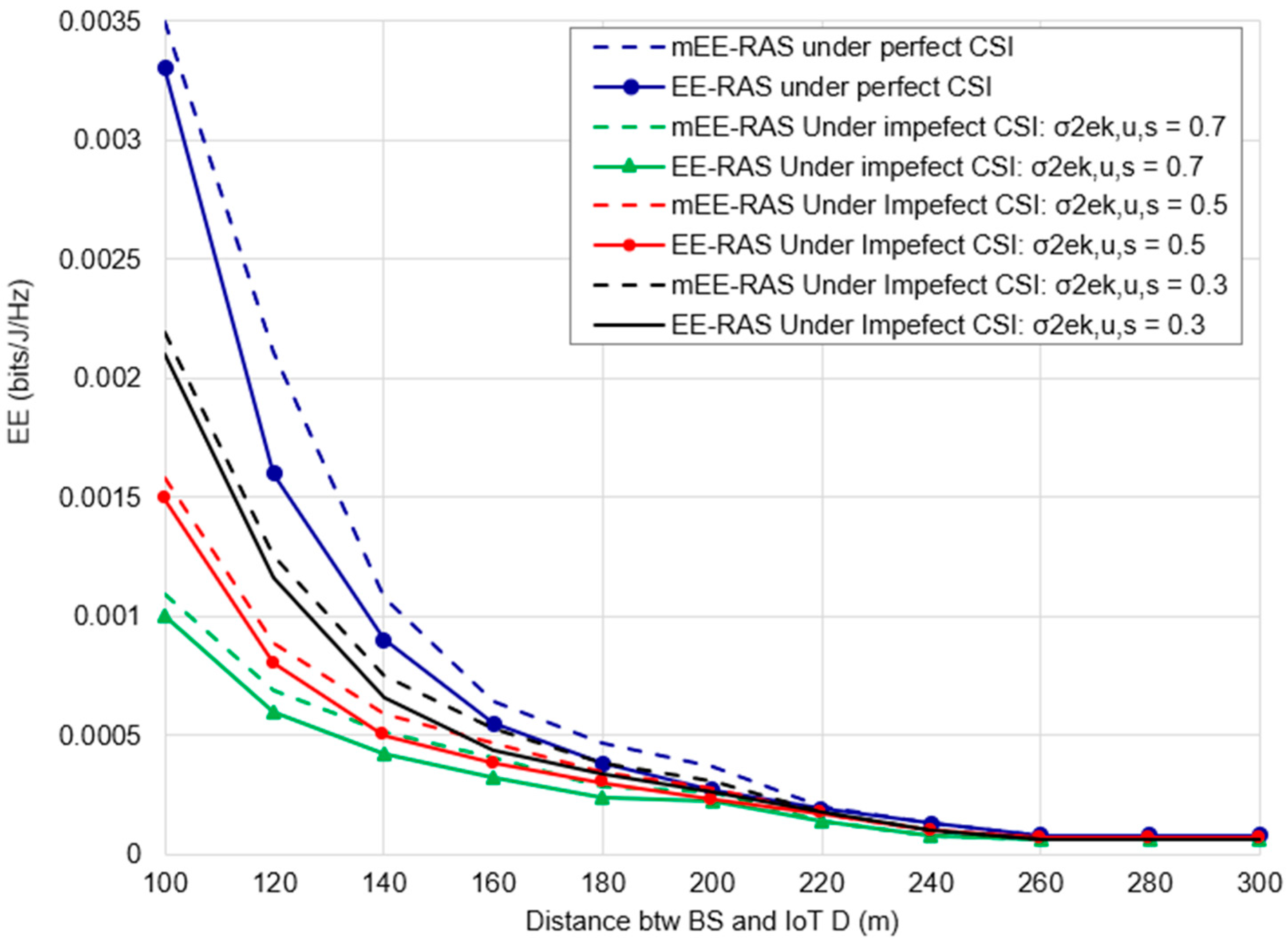
5.2.2. Imperfect CSI Impact on EE

Next, we analyze the impact of imperfect CSI on the system EE. The BSs estimate the channels during uplink training and the MMSE estimator is applied. Channel estimation error parameters ( σ 2 E k , u , s ) represent the CSI estimation accuracy. Figure 4 illustrates the system EE versus the distance between IoT UE and BS while considering various channel errors for the proposed mEE-RAS and EE-RAS. As expected, the EE degrades with increasing σ 2 E k , u , s due to inaccurate beamforming as a result of channel estimation error. However, the proposed scheme shows stronger resilience and retains higher EE across the σ 2 E k , u , s range. With perfect CSI ( σ 2 E k , u , s = 0 ), the mEE-RAS achieved improvement in terms of EE by 12.75%, having an average EE of 7.95 × 10−4 bits/J/Hz. Also, under imperfect CSI, the mEE-RAS outperformed the EE-RAS with percentage improvements of 10.25%, 8.50%, and 6.97% while having corresponding average EE values of 3.32 × 10−4 bits/J/Hz, 4.21 × 10−4 bits/J/Hz, and 5.34 × 10−4 bits/J/Hz when the channel estimation errors were 0.7, 0.5, and 0.3, respectively. The robustness can be attributed to the unique UE–BS links. Beamforming optimization can adapt more easily to channel uncertainties when interference from other BSs is intrinsically avoided.
Subsequently, this means establishing explicit UE–BS connections that continue to provide EE enhancements under imperfect CSI. However, the marginal benefits reduce as the CSI quality degrades.

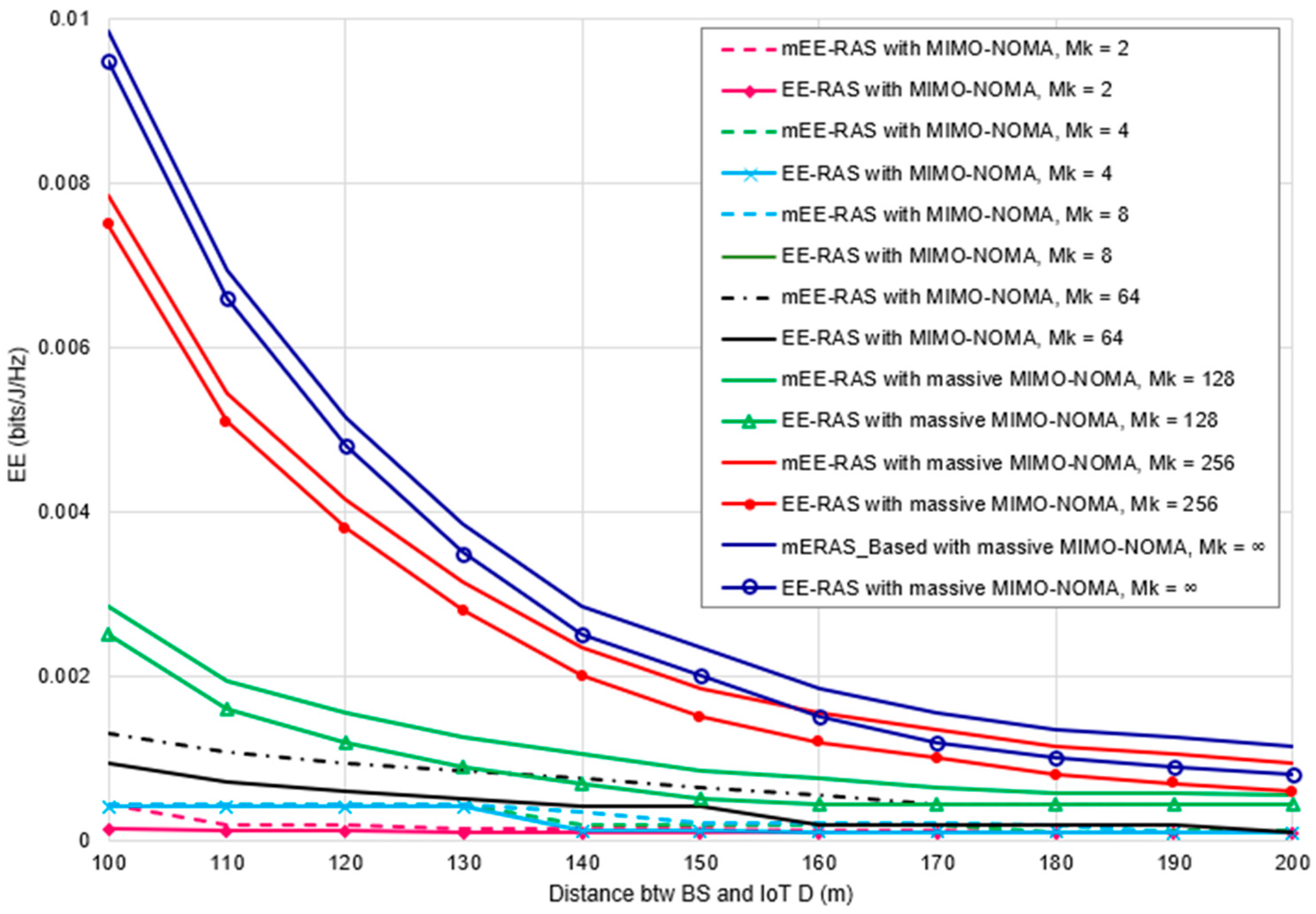
5.2.3. EE vs. Number of Antennas (MIMO and Massive MIMO)

We now evaluate the EE for conventional MIMO and massive MIMO configurations. Figure 5 plots the system EE against Mk for both proposed mEE-RAS and EE-RAS schemes. It is observed that the rate at which system EE increases slows down as the total number of antennas increases; however, the system EE for those MIMO configurations with higher antenna numbers remains significantly higher. This is because, with a higher antenna number, the algorithm can fairly assign the optimal antenna number to IoT UEs. The mEE-RAS achieved EE improvement of 30.13%, 26.89%, 10.79%, and 123.12%, having corresponding average EE values of 1.42 × 10−4 bits/J/Hz, 2.59 × 10−4 bits/J/Hz, 2.86 × 10−4 bits/J/Hz, and 7.19 × 10−4 bits/J/Hz when Mk was 2, 4, 8, and 64 over EE-RAS in the conventional MIMO configuration. The mEE-RAS also achieved improvements in massive MIMO configuration of 38.14%, 26.28%, and 20.63%, with corresponding average EE values of 1.14 × 10−3 bits/J/Hz, 2.80 × 10−3 bits/J/Hz, and 3.47 × 10−3 bits/J/Hz when Mk was set to 128, 256, and ∞, respectively.
By implication, optimizing UE–BS connections lowers the required number of antennas to achieve maximal EE. Appreciable EE gains are obtained across the Mk range, with higher benefits for low and moderate Mk. Dedicated WPT links enhance interference management even with fewer antennas.

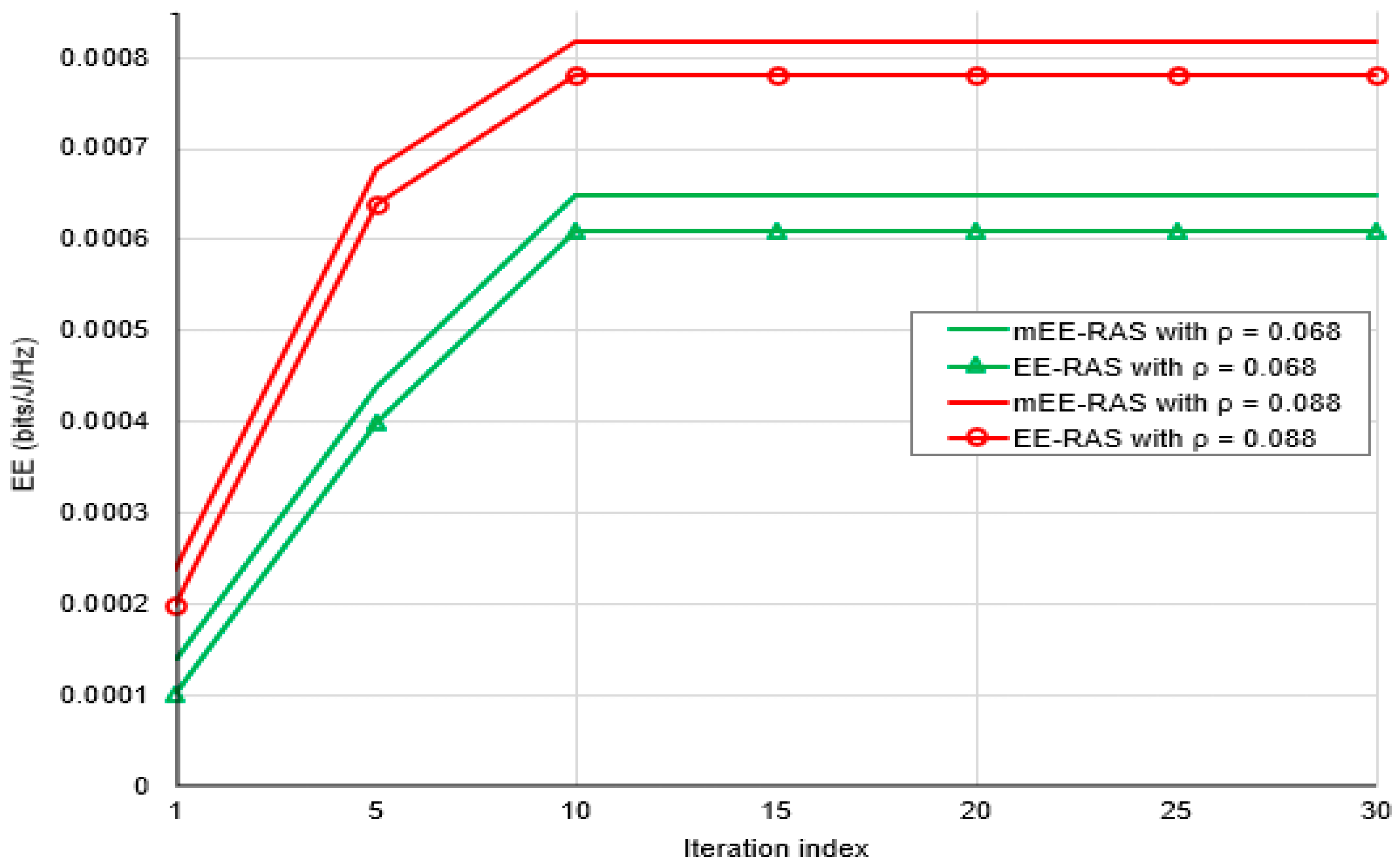
5.2.4. Convergence Analysis

Finally, we analyze the convergence of the mEE-RAS and the EE-RAS schemes in solving the EE maximization problem. Figure 6 plots the EE versus iteration index for different convergence parameter ρ values. It is observed that larger ρ leads to faster convergence at the cost of the optimality gap. The proposed mEE-RAS achieves a higher EE objective but follows similar convergence behavior as the EE-RAS. The mEE-RAS achieved an EE improvement of 11.31%, having an average EE of 5.45 × 10−4 bits/J/Hz when ρ was set to 0.068. The mEE-RAS also improved the EE-RAS by 7.09%, having an average EE of 7.15 × 10−4 bits/J/Hz when ρ was 0.088.
Therefore, distributed optimization enables scalable implementation for massive MIMO–NOMA networks integrated with WPT capabilities. The ADMM approach provably converges to achieve high-quality solutions while reducing computational complexity.

6. Conclusions

In this paper, we have proposed a UE–BS connection model to mitigate CCI in wireless-powered massive MIMO–NOMA networks. An energy-efficient resource allocation scheme was developed that integrates the UE–BS connection approach with joint optimization of transmit power, time, antenna, and subcarrier allocation. Simulation results demonstrate significant improvements in system EE by establishing dedicated UE–BS connections for WPT. Reducing CCI allows more efficient wireless charging of the UE, which translates to higher uplink data rates and EE performance. Appreciable gains are maintained even under imperfect CSI due to the unique UE–BS links.
In conclusion, the UE–BS connection model offers a promising technique to mitigate CCI that leverages the system topology and associations. Integrating it with energy-efficient resource allocation unlocks substantial EE enhancements in WPT-enabled massive MIMO–NOMA networks. Important future work includes investigating a resource allocation scheme that considers security and that can accommodate different IoT UE QoS requirements as well as exploring unmanned aerial vehicle-assisted or intelligent reflection surfaces-enabled massive MIMO–NOMA to improve the EE of the WPT-based networks.

Author Contributions

Conceptualization, A.E.E. and K.C.O.; methodology, S.T.T. and A.E.E.; software, O.J.; validation: A.E.E., K.C.O., S.T.T., O.J. and K.A.; formal analysis: S.T.T.; investigation, C.A.A.; resources, J.A.; data curation: A.L.I.; writing—original draft preparation, A.E.E., S.T.T. and A.L.I.; writing—review and editing: K.C.O.; visualization, K.A. and O.J.; supervision: C.A.A.; project administration: A.L.I.; funding acquisition, K.C.O. and A.L.I. All authors have read and agreed to the published version of the manuscript.

Funding

This research was funded in part by the Tertiary Education Trust Fund (Tetfund) Nigeria under the grant Number (“TETF/ES/ UNIV/IMO STATE/TSAS/2021”). Reference Project: Autonomous Driverless Cars using Resilient AI.

Institutional Review Board Statement

This study was conducted in accordance with the ethical standards and approved by the Institutional Review Board (IRB) of University of Chichester, UK.

Informed Consent Statement

The authors declare that they have no known competing financial interests or personal relationships that could have influenced the work reported in this paper.

Data Availability Statement

No new data were created or analyzed in this study. Data sharing is not applicable to this article.

Conflicts of Interest

The authors declare no conflicts of interest.

References

  1. Gandotra, P.; Jha, R.K. A survey on green communication and security challenges in 5G wireless communication networks. J. Netw. Comput. Appl. 2017, 96, 39–61. [Google Scholar] [CrossRef]
  2. Shahraki, A.; Abbasi, M.; Piran, M.J.; Taherkordi, A. A comprehensive survey on 6G networks: Applications, core services, enabling technologies, and future challenges. arXiv 2021, arXiv:2101.12475. [Google Scholar]
  3. Patzold, M. Countdown for the full-scale development of 5G new radio [mobile radio]. IEEE Veh. Technol. Mag. 2018, 13, 7–13. [Google Scholar] [CrossRef]
  4. Hao, W.; Chu, Z.; Zhou, F.; Yang, S.; Sun, G.; Wong, K.-K. Green communication for NOMA-based CRAN. IEEE Internet Things J. 2018, 6, 666–678. [Google Scholar] [CrossRef]
  5. Mai, T.C.; Ngo, H.Q.; Duong, T.Q. Uplink spectral efficiency of cell-free massive MIMO with multi-antenna users. In Proceedings of the 2019 3rd International Conference on Recent Advances in Signal Processing, Telecommunications & Computing (SigTelCom), Hanoi, Vietnam, 21–22 March 2019; pp. 126–129. [Google Scholar]
  6. Ding, Z.; Fan, P.; Poor, H.V. Impact of user pairing on 5G Non-Orthogonal Multiple Access. arXiv 2014, arXiv:1412.2799. [Google Scholar]
  7. Zewde, T.A.; Gursoy, M.C. NOMA-based energy-efficient wireless powered communications. IEEE Trans. Green Commun. Netw. 2018, 2, 679–692. [Google Scholar] [CrossRef]
  8. Chen, L.; Hu, B.; Xu, G.; Chen, S. Energy-efficient power allocation and splitting for mmWave beamspace MIMO-NOMA with SWIPT. IEEE Sens. J. 2021, 21, 16381–16394. [Google Scholar] [CrossRef]
  9. Yang, Z.; Xu, W.; Pan, Y.; Pan, C.; Chen, M. Energy-efficient resource allocation in machine-to-machine communications with multiple access and energy harvesting for IoT. IEEE Internet Things J. 2018, 5, 229–245. [Google Scholar] [CrossRef]
  10. Wang, Z.; Lin, Z.; Lv, T.; Ni, W. Energy-efficient resource allocation in massive MIMO-NOMA networks with wireless power transfer: A distributed ADMM approach. IEEE Internet Things J. 2021, 8, 14232–14247. [Google Scholar] [CrossRef]
  11. Guo, N.; Yuan, X.; Hu, Y.; Schmeink, A. Fairness-aware resource allocation in multi-source WPCN in the finite blocklength regime. IEEE Access 2023, 11, 32348–32364. [Google Scholar] [CrossRef]
  12. Li, J.; Jiang, H. Research on the SWIPT system throughput based on interference signal energy collecting. KSII Trans. Internet Inf. Syst. 2023, 17, 2170. [Google Scholar]
  13. Le, A.T.; Tran, D.H.; Le, C.B.; Tin, P.T.; Nguyen, T.N.; Ding, Z.; Poor, H.V.; Voznak, M. Power beacon and NOMA-assisted cooperative IoT networks with co-channel interference: Performance analysis and deep learning evaluation. IEEE Trans. Mob. Comput. 2023, 23, 7270–7283. [Google Scholar] [CrossRef]
  14. Wang, Y.; Li, P.; Tan, D.; Zhang, J.; Duan, X.; Chen, Y.; Zhao, D. A game-based computation offloading method in vehicular multiaccess edge computing networks. IEEE Internet Things J. 2020, 7, 4987–4996. [Google Scholar] [CrossRef]
  15. Liu, X.; Zheng, J.; Zhang, M.; Li, Y.; Wang, R.; He, Y. A game-based computing resource allocation scheme of edge server in vehicular edge computing networks considering diverse task offloading modes. Sensors 2023, 24, 69. [Google Scholar] [CrossRef] [PubMed]
  16. Tian, H.; Yan, M.; Dai, L.; Yang, P. Joint communication and computation resource scheduling of a solar-powered UAV-assisted communication system for platooning vehicles. In Proceedings of the 2023 9th International Conference on Mechanical and Electronics Engineering (ICMEE), Xi’an, China, 17–19 November 2023; pp. 49–54. [Google Scholar]
  17. Gupta, S.; Patel, N.; Kumar, A.; Jain, N.K.; Dass, P.; Hegde, R.; Rajaram, A. Intelligent resource optimization for scalable and energy-efficient heterogeneous IoT devices. Multimed. Tools Appl. 2024, 24, 1–25. [Google Scholar] [CrossRef]
  18. Wang, X.; Li, J.; Ning, Z.; Song, Q.; Guo, L.; Guo, S.; Obaidat, M.S. Wireless powered mobile edge computing networks: A survey. ACM Comput. Surv. 2023, 55, 1–37. [Google Scholar] [CrossRef]
  19. Zhu, T.; Li, J.; Cai, Z.; Li, Y.; Gao, H. Computation scheduling for wireless powered mobile edge computing networks. In Proceedings of the IEEE INFOCOM 2020-IEEE Conference on Computer Communications, Toronto, ON, Canada, 6–9 July 2020; pp. 596–605. [Google Scholar]
  20. Mustafa, E.; Shuja, J.; uz Zaman, S.K.; Jehangiri, A.I.; Din, S.; Rehman, F.; Mustafa, S.; Maqsood, T.; Khan, A.N. Joint wireless power transfer and task offloading in mobile edge computing: A survey. Clust. Comput. 2022, 25, 2429–2448. [Google Scholar] [CrossRef]
  21. Ji, L.; Guo, S. Energy-efficient cooperative resource allocation in wireless powered mobile edge computing. IEEE Internet Things J. 2018, 6, 4744–4754. [Google Scholar] [CrossRef]
  22. Barman, S.; Reza, A.W.; Kumar, N.; Karim, M.E.; Munir, A.B. Wireless powering by magnetic resonant coupling: Recent trends in wireless power transfer system and its applications. Renew. Sustain. Energy Rev. 2015, 51, 1525–1552. [Google Scholar] [CrossRef]
  23. Ngo, H.Q.; Larsson, E.G.; Marzetta, T.L. Energy and spectral efficiency of very large multiuser MIMO systems. IEEE Trans. Commun. 2013, 61, 1436–1449. [Google Scholar]
  24. Dai, L.; Wang, B.; Peng, M.; Chen, S. Hybrid precoding-based millimeter-wave massive MIMO-NOMA with simultaneous wireless information and power transfer. IEEE Trans. Commun. 2019, 37, 131–141. [Google Scholar] [CrossRef]
  25. Na, Z.; Zhang, M.; Jia, M.; Xiong, M.; Gao, Z. Joint uplink and downlink resource allocation for the Internet of Things. IEEE Access 2019, 7, 15758–15766. [Google Scholar] [CrossRef]
  26. Chen, X.; Ng, D.W.K.; Yu, W.; Larsson, E.G.; Al-dhahir, N.; Schober, R. Massive access for 5G and beyond. IEEE J. Sel. Areas Commun. 2021, 39, 615–637. [Google Scholar] [CrossRef]
  27. Prasad, K.N.R.S.V.; Hossain, E.; Bhargava, V.K. Energy efficiency in massive MIMO-based 5G networks: Opportunities and challenges. IEEE Wirel. Commun. 2017, 24, 86–94. [Google Scholar] [CrossRef]
  28. Zhong, C.; Suraweera, H.A.; Zheng, G.; Krikidis, I.; Zhang, Z. Improving the throughput of wireless powered dual-hop systems with full duplex relaying. IEEE Int. Conf. Commun. 2015, 2015, 4253–4258. [Google Scholar] [CrossRef]
  29. Ponnimbaduge Perera, T.D.; Jayakody, D.N.K.; Sharma, S.K.; Chatzinotas, S.; Li, J. Simultaneous wireless information and power transfer (SWIPT): Recent advances and future challenges. IEEE Commun. Surv. Tutor. 2018, 20, 264–302. [Google Scholar] [CrossRef]
  30. Shen, S.; Clerckx, B. Joint waveform and beamforming optimization for MIMO wireless power transfer. IEEE Trans. Commun. 2021, 69, 5441–5455. [Google Scholar] [CrossRef]
  31. Bi, S.; Zeng, Y.; Zhang, R. Wireless powered communication networks: An overview. IEEE Wirel. Commun. 2016, 23, 10–18. [Google Scholar] [CrossRef]
  32. Xu, B.; Chen, Y.; Carrión, J.R.; Zhang, T. Resource allocation in energy-cooperation enabled two-tier NOMA HetNets toward green 5G. IEEE J. Sel. Areas Commun. 2017, 35, 2758–2770. [Google Scholar] [CrossRef]
  33. Chang, Z.; Wang, Z.; Guo, X.; Yang, C.; Han, Z.; Ristaniemi, T. Distributed resource allocation for energy efficiency in OFDMA multicell networks with wireless power transfer. IEEE J. Sel. Areas Commun. 2019, 37, 345–356. [Google Scholar] [CrossRef]
  34. Lee, K.; Hong, J.P. Energy-efficient resource allocation for simultaneous information and energy transfer with imperfect channel estimation. IEEE Trans. Veh. Technol. 2016, 65, 2775–2780. [Google Scholar] [CrossRef]
  35. Wei, E.; Ozdaglar, A. Distributed alternating direction method of multipliers. In Proceedings of the 2012 IEEE 51st IEEE Conference on Decision and Control (CDC), Maui, HI, USA, 10–13 December 2012; pp. 5445–5450. [Google Scholar] [CrossRef]
  36. Boyd, S.; Parikh, N.; Chu, E.; Peleato, B.; Eckstein, J. Distributed optimization and statistical learning via the alternating direction method of multipliers. Found. Trends® Mach. Learn. 2011, 3, 1–122. [Google Scholar]
  37. Li, H.; Song, L.; Debbah, M. Energy efficiency of large-scale multiple antenna systems with transmit antenna selection. IEEE Trans. Commun. 2014, 62, 638–647. [Google Scholar] [CrossRef]
  38. Okafor, K.C.; Adebisi, B.; Akande, A.O.; Anoh, K. Agile gravitational search algorithm for cyber-physical path-loss modelling in 5G connected autonomous vehicular network. Veh. Commun. 2024, 45, 100685. [Google Scholar] [CrossRef]
  39. Okafor, K.C. Bamidele Adebisi, Kelvin Anoh Lightweight multi-hop routing protocol for resource optimisation in edge computing networks. Internet Things 2023, 22, 100758. [Google Scholar] [CrossRef]
Figure 1. Three cell scenario system architecture.
Technologies 12 00119 g001
Figure 2. Two-time slot protocol.
Technologies 12 00119 g002
Figure 3. Comparison between mEE-RAS and existing EE-RAS benchmark schemes [10].
Technologies 12 00119 g003
Figure 4. Influence of various channel estimation errors on the system EE.
Technologies 12 00119 g004
Figure 5. System EE vs. communication distance under different antenna numbers, Mk.
Technologies 12 00119 g005
Figure 6. Convergence of the mEE-RAS versus EE-RAS.
Technologies 12 00119 g006
Table 1. Comparative overview of mEE-RAS against EE-RAS schemes for complexity deliberation.
AspectEE-RAS SchememEE-RAS Scheme
Optimization ProblemResource allocation in NOMA MIMO with WPTResource allocation in NOMA MIMO with WPT and UE–BS connection model
ConstraintsC1–C6 (max power, energy transfer time, power non-negativity, rate, antenna control, and subcarrier allocation)C1–C7 (max power, energy transfer time, power non-negativity, rate, antenna control, subcarrier allocation, and UE–BS connection)
Iterative AlgorithmADMM (Alternating Direction Method of Multipliers)D-ADMM (Distributed Alternating Direction Method of Multipliers)
Number of Iterations (K)Problem-specificProblem-specific
Complexity of Solving SubproblemsProblem-specific, may involve matrix operationsProblem-specific, may involve matrix operations
Overall Computational ComplexityK Complexity of solving x-subproblem + Complexity of solving z-subproblem)K (Complexity of solving x-subproblem + complexity of solving z-subproblem)
Size of Optimization Variables M a x P , t , N , C , x P , t ^ , N ^ , C ^ ,   a n d   x ^ . M a x P , t , N , C , x P , t ~ , N ~ , C ~ , a n d   x ~ .
UE–BS Connection Model IntegrationNot applicableIntegrated for joint optimization of parameters
Joint Optimization of ParametersNot applicableJoint optimization of transmit power, time allocation, antenna selection, and subcarrier assignment
Co-channel interference MitigationConventional WPT to mitigate co-channel interference during the wireless charging phaseUE–BS connection model used to assign each UE to a single BS for WPT to mitigate co-channel interference during the wireless charging phase
Energy-Efficient Resource AllocationNot applicableEnergy-efficient resource allocation scheme integrated with the UE–BS connection approach
Comparative AnalysisStandard resource allocation model with ADMMEnhanced model with UE–BS connection, joint optimization, interference mitigation, and energy efficiency
Advantages of Scenario 2 over Scenario 1Mitigates co-channel interference during the wireless charging phase, energy-efficient resource allocation, and joint optimization of multiple parametersOffers additional benefits of UE–BS connection, interference mitigation, and energy efficiency in resource allocation.
Model equation for solving x-problem arg m i n   x f x + ρ 2 A x + B z k c + y k 2 10 0 arg m i n   x f x + ρ 2 A x + B z k c + y k 2 10 2 .
Model equation for solving z-problem arg m i n   x f x + ρ 2 A x k + 1 + B z c + y k 2 10 0 arg m i n   x f x + ρ 2 A x k + 1 + B z c + y k 2 10 2
Table 2. Simulation Parameters.
S/NParameter (unit)Value
1Base stations, K6
2No of users, U15
3Cell radius (m)500
4Subcarrier, S20–40
5Pbs.max (dBm)46
6Puser.max (dBm)23
7Rmin (bit/s/Hz)0.1
8αk,u1/75
9Pmin (mW)20.3
10PLNA (mW)20
11η0.8
12e10−7
13B (Hz)1
14PDAC (mW)10
15PADC (mW)10
16Pfilr (mW)2.5
17Ptilt (mW)2.5
18Psyn (mW)50
19PIFA (mW)3
Disclaimer/Publisher’s Note: The statements, opinions and data contained in all publications are solely those of the individual author(s) and contributor(s) and not of MDPI and/or the editor(s). MDPI and/or the editor(s) disclaim responsibility for any injury to people or property resulting from any ideas, methods, instructions or products referred to in the content.

