Article

Experimental Benchmarking of Existing Offline Parameter Estimation Methods for Induction Motor Vector Control

by
Butukuri Koti Reddy
1,
Krishna Sandeep Ayyagari
2,
Yemula Pradeep Kumar
3,
Nimay Chandra Giri
4,*,
Panganamamula Venkata Rajgopal
5,
Georgios Fotis
6,* and
Valeri Mladenov
7,*
1
Department of Atomic Energy, Heavy Water Plant, Manuguru 507116, India
2
Burns & McDonnell, Atlanta, GA 30345, USA
3
Indian Institute of Technology, Hyderabad 502284, India
4
Department of Electronics and Communication Engineering, Centurion University of Technology and Management, Jatni 752050, India
5
Bharat Heavy Electricals Ltd., Research and Development, Hyderabad 502032, India
6
Centre for Energy Technologies, Aarhus University, Birk Centerpark 15, Innovatorium, 7400 Herning, Denmark
7
Department Fundamentals of Electrical Engineering, Technical University of Sofia, 8 Kliment Ohridski Blvd., Block 12, 1000 Sofia, Bulgaria
*
Authors to whom correspondence should be addressed.
Technologies 2024, 12(8), 123; https://doi.org/10.3390/technologies12080123
Submission received: 4 July 2024 / Revised: 24 July 2024 / Accepted: 30 July 2024 / Published: 1 August 2024
(This article belongs to the Collection Electrical Technologies)

Abstract

:
Induction motors dominate industrial applications due to their unwavering reliability. However, optimal vector control, critical for maximizing dynamic performance, hinges on accurate parameter estimation. This control strategy necessitates precise knowledge of the motor’s parameters, obtainable through experimentation or calculation based on its design specifications. Numerous methods, ranging from traditional to computational, have been proposed by various researchers, often relying on specific assumptions that might compromise the performance of modern motor control techniques. This paper meticulously reviews the most frequently utilized methods and presents experimental results from a single motor. We rigorously compare these results against established benchmark methods, including IEEE Standard 112-2017, and subsequently identify the superior approach, boasting a maximum error of only 6.5% compared to 19.65% for competing methods. Our study investigates the parameter estimation of induction motor. The methodology primarily utilizes RMS values for measurement tasks. Moreover, the impact of harmonics, particularly when an induction motor is supplied by an inverter is briefly addressed. The pioneering contribution of this work lies in pinpointing a more accurate parameter estimation method for enhanced vector control performance. These findings pave the way for exceptional vector control, particularly at lower speeds, ultimately elevating both vector control and drive performance.

1. Introduction

Induction motors are pivotal in industrial applications due to their robustness and efficiency. Although the equivalent circuit model, a simplified representation of an induction motor’s electrical and magnetic behavior, has been a foundational tool in both industry and academia, advancements in vector control demand more precise parameter estimation for optimized performance. Despite the extensive research using methods ranging from classical equations to advanced computational models like artificial neural networks and fuzzy logic, these approaches often fall short in accuracy and computational efficiency. This paper presents a rigorous experimental and comparative analysis of parameter estimation techniques for induction motors, identifying a superior method that integrates traditional and innovative computational methods. Unlike previous studies, which often rely on either purely theoretical or limited experimental approaches, our work combines robust field experiments with a comparative analysis across various estimation methods to benchmark and enhance the accuracy of vector control. Our novel contribution is developing and validating an enhanced parameter estimation technique that outperforms existing methods, providing a maximum error reduction to 6.5% from 19.65% observed in other approaches. This advancement significantly improves the dynamic performance of induction motors, particularly at lower speeds, which is critical for industries seeking higher efficiency and reliability. Additionally, by adhering to and extending the capabilities of IEEE Standard Test Procedure for Polyphase Induction Motors and Generators (IEEE 112-2017, Section 5), our approach meets international industry standards while setting a new benchmark for accuracy and practical applicability in vector control.
Fitzgerald et al. [1] provide a foundational understanding but often overlook subtleties such as non-linearities introduced by operational conditions. According to [2], accurate parameter estimation is essential for effective vector control of induction motors. Recent advancements have incorporated computational techniques such as artificial neural networks [3], fuzzy logic, and model-based methods to enhance accuracy; however, these approaches still struggle with computational overhead and the need for extensive training datasets which may not be feasible in all operational settings. In [4], an enhanced hybrid model that integrates voltage and current has been developed for better flux observation. This model smoothly merges the newly proposed voltage improvement with the existing current model. Hybrid models that integrate voltage and current for better flux observation have also been developed [5]. However, these approaches often require extensive training datasets and may not be feasible in all operational settings. Moreover, existing literature frequently separates the discussion of theoretical accuracy from practical viability. For example, the widely used model-based approaches as discussed in [6] are proficient in controlled laboratory conditions but may not adapt well to the variable and harsh conditions of real-world industrial environments. This gap underscores a critical oversight in current research—balancing theoretical precision with practical applicability. Our work addresses this gap by integrating rigorous field experiments with a comparative analysis across traditional and modern computational methods, thus providing a comprehensive evaluation of their performance in real-world settings. Notably, our methodological framework not only tests these techniques against standardized benchmarks but also evaluates their practical implementation in a typical industrial scenario, offering a unique contribution to the field that prioritizes both accuracy and operational feasibility.
A novel online parameter identification algorithm was proposed in [7,8,9] for induction motors based on the improved differential evolution and multiple adaptive Kalman filter, which achieved accurate parameter estimation and fast convergence. The work in [10] estimator used is based on a least squares algorithm but includes a dead zone that ensures robustness and a variable forgetting factor that is based on the constant information principle. The simulation results show that the adaptive estimator can efficiently estimate the states and parameters of the induction machine with a fast convergence rate despite the initial parametric errors. The numerical method used in [11] is claimed as a high precision method by the authors. The work in [12] outlines the process of online parameter identification and continuous updating within the controller of induction motor drives (IMDs). The Stator Winding Resistance Estimation Technique for Induction Motor Drives Using DC-Signal Injection Suited for Low Inertia Applications is proposed in [13].
The work in [14] presents a combined method for estimating equivalent circuit parameters of cage induction motors using a two-stage Particle Swarm Optimization algorithm and the approximation of rotor parameters as a function of speed due to the skin effect. The method is validated on eight ABB-manufactured two-pole induction motors, demonstrating a mean absolute relative error below 5% when comparing torque–speed characteristics with manufacturer data.
The authors in [15] present an improved Moth Flame Optimization (IMFO) technique for more accurate parameter estimation in induction motors using a steady-state equivalent circuit. The IMFO outperforms Moth Flame Optimization (MFO), Particle Swarm Optimization (PSO), Flower Pollination Algorithm (FPA), and Tunicate Swarm Algorithm (TSA) in addressing parameter estimation challenges. The work in [16] presents a novel meta-heuristic algorithm using dynamic response equations for motor model parameter estimation, leveraging steady-state and transient-state conditions to streamline the search process and reduce random parameters. Experimental tests on two motors assessed the algorithm’s effectiveness. Three diverse algorithms (Gray Wolf Optimizer, Jaya Algorithm, and Cuckoo Search Algorithm) demonstrated the broader applicability of these enhancements, consistently achieving comparable error rates with 10 to 50% fewer iterations than the original method.
Previous research has investigated various methods for induction motor parameter estimation and anomaly detection, including the use of artificial neural networks, fuzzy logic, and model-based methods [17,18,19,20,21,22]. However, these methods have limitations in terms of accuracy and computational complexity. The above limitations can be overcome by the current research trends in induction motor parameter estimation and vector control methods. In summary, while the field of induction motor parameter estimation is rich with diverse approaches, the need for a method that combines high accuracy with practical applicability remains unmet. Our study seeks to fill this void by presenting a methodology that benchmarks existing techniques against robust field tests, ensuring that the superior method identified not only meets but exceeds the standard expectations of industrial applications. The major contributions of this work are as follows:
  • This paper presents the practical determination of machine parameters of an induction motor (IM) using very good practical testing methods (meeting International Industry Practices like IEEE Standards). The motor used for Testing is a 90 kW (120 HP)/NEMA-B/IM.
  • The values of the machine parameters obtained by the industry standard test method followed in the practical physical testing of the selected IM were found to be very near to those obtained in the other methods compared.
  • Identification of best-performing method with the lowest error for vector control.

2. Materials and Methods

The equivalent circuit parameters of an induction motor play an important role in the vector control of motor. These parameters, including the resistance (R1), inductance (L1), and mutual inductance (Lm), are used to model the behavior of the motor and predict its performance. These parameters can be determined experimentally or calculated from the motor’s design specifications or by field tests.

2.1. The Proposed Method

In this work, we propose a novel parameter estimation method that combines traditional calculation techniques with modern computational tools. The workflow of our proposed method is shown in Figure 1.
The methods used in this work are calculations from the formulae available in standard textbooks, field experiments, simulations with MATLAB and estimations with excel spread sheet.

2.2. Steps of the Proposed Method

  • Initial Parameter Estimation:
    • The No-Load Test: Measure the stator winding resistance (R1) using a micro-ohm meter. Perform the no-load test by running the motor without any load and recording the voltage and current.
    • The Short-Circuit Test: Conduct the short-circuit test by locking the rotor and applying a low voltage to measure the rotor resistance (R2) and leakage reactance (X2).
  • Advanced Computational Techniques:
    • Develop a spreadsheet program to automate calculations based on the collected test data.
    • Simulate the motor using MATLAB to validate the experimental results and refine the parameter estimates.
  • Field Validation:
    • Compare the estimated parameters with those obtained from established benchmark methods, including IEEE Standard 112-2017.
    • Validate the results through field tests on a 90 kW (120 HP) induction motor.

2.3. Description of Methodology

Vector control algorithms use this information to control the speed of the induction motor by adjusting the stator current to produce a desired torque and phase angle. In vector control of an induction motor, the stator voltage and frequency are controlled to achieve a desired torque and speed with high dynamic response. This control method requires accurate knowledge of the motor’s electrical parameters, such as the stator and rotor resistances and inductances, as well as the magnetizing inductance.
In the induction motor vector control method, the flux in rotor is controlled by stator current control. To regulate the rotor flux, it is necessary to have information about the rotor’s position and resistance. If the parameter values are not accurately estimated or identified, the vector control method will not be able to generate the correct voltage and frequency signals to the motor, resulting in reduced control performance [23]. This can lead to problems such as low torque and reduced dynamic performance. Numerous approaches for parameter estimation exist to attain accurate control with poor accuracy. Also, the variation in the machine parameters results in an inaccurate mathematical model, which is basis for vector control. Then, the high dynamic which is the purpose for using the vector control will not be achieved
There are two types of equivalent circuits for induction motors [1] namely (a) approximate equivalent circuit, in which some of the parameters in the circuit are ignored or making certain assumptions. This model is used for initial design and analysis of the motor. It brings parameters such as core resistance, leakage inductance, and magnetizing inductance to the front side of the circuit. (b) Exact equivalent circuit, in which all the parameters in the motor circuit, such as stator and rotor resistance, leakage inductance, magnetizing inductance, and rotor reactance are placed in their actual position. The exact equivalent circuit is more complex than the approximate equivalent circuit and is used for more accurate predictions of motor performance under different operating conditions and is used for modelling and simulation of the motor [24]. The schematic diagrams of both models are shown in Figure 2.
R1 is the winding resistance of the stator,
X1 is the reactance of the stator winding,
R2 is the winding resistance of the rotor,
X2 is the reactance of the rotor winding,
Rc is the core loss component,
XM is the magnetizing reactance of the winding,
RL is the load resistance, and
s is Slip of motor at rated speed.
Rotor resistance is as in Equation (1),
R 2 = s E 2 / ( R 2 ) 2 + ( s X 2 ) 2
Load resistance is as in Equation (2),
R L = R 2 [ ( 1 s ) / s ] )
Consequently, an accurate method is needed to determine the parameters. This project proposes to find out the best among the existing parameter estimation methods. In this work, field tests are conducted as recommended in the internationally accepted industry standard of IEEE 112-2017 [25]. Also, the estimations are made with some peer models for comparison to achieve an accurate equivalent circuit. This work helps in identifying the more accurate method for an improved vector control and drive performance. The following tests are performed on a 90 kW/120 HP induction motor to determine its equivalent circuit parameters. The motor has been dismantled to separate stator and rotor for resistance measurement.
(a)
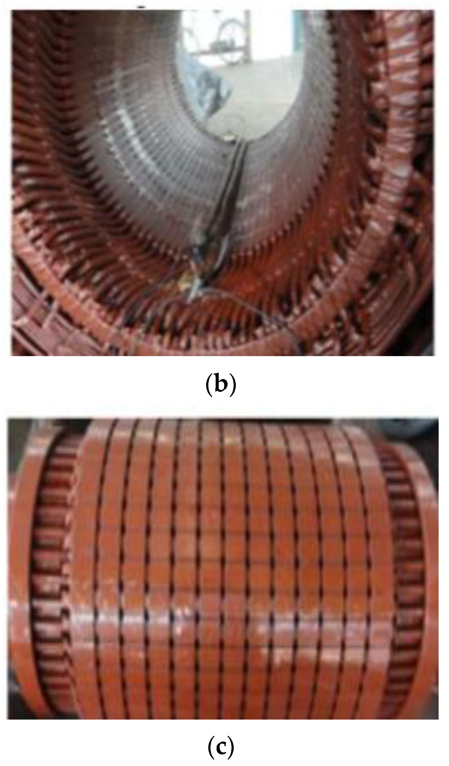
The no-rotor test: The no-rotor test is performed by disconnecting from load and dismantling the motor and measured the stator winding resistance (R1) with the help of a micro-ohm meter. This parameter will be useful in estimating the stator copper loss.
(b)
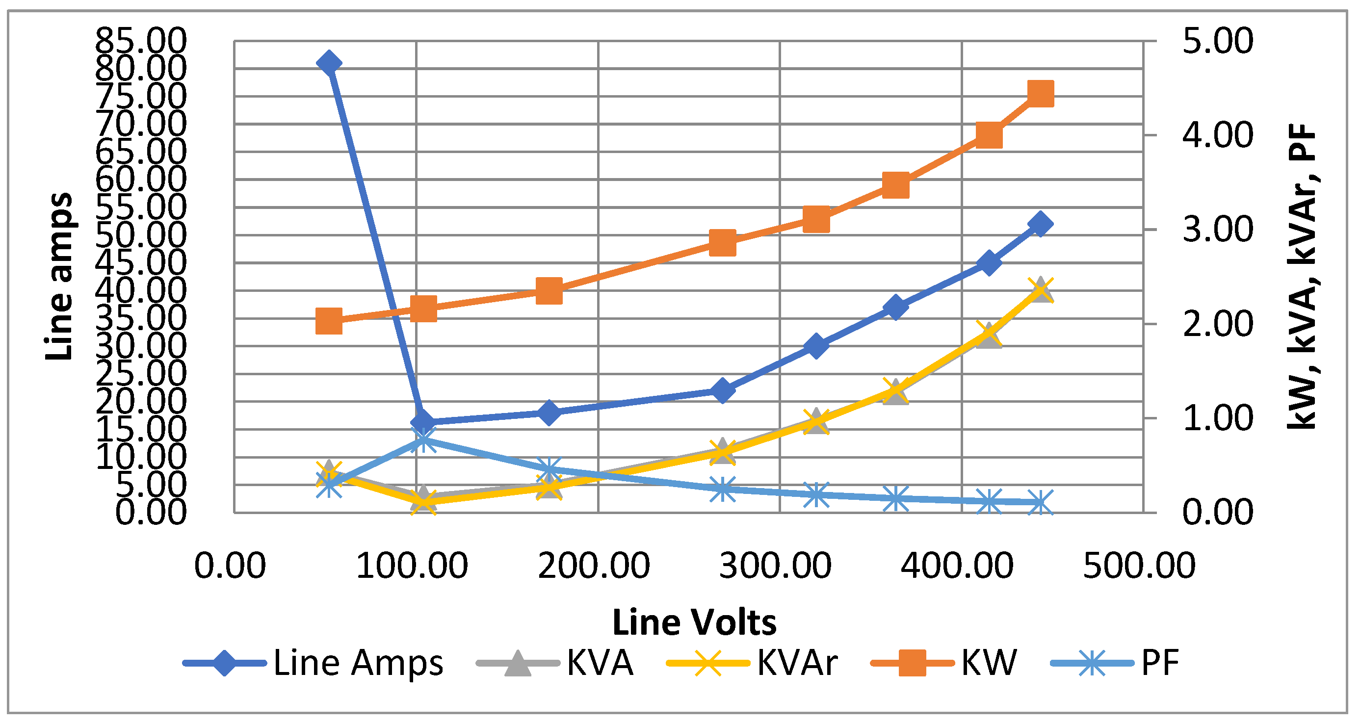
The no-load test: A no-load test is performed by running the motor without any load and measured the voltage and current of the motor. Readings are taken with varying voltage at rated frequency, as per the IEEE 112 guidelines. Auto-transformer of 100 kVA, 0–460 V, 50 Hz is used for this test. The data collected from this test are used to calculate the resistance (Rc) and leakage reactance of core (Xm) of the motor. These data are also used to separate the rotational and iron loss components from no-load loss.
(c)
The short-circuit test: A short-circuit or locked-rotor test is performed by locking the rotor. Three phase low voltage at rated frequency is applied to the motor so that the rated current is drawn by it. Later, the short circuit current is normalized to rated voltage with standard formulae. The data collected from this test are used to calculate the rotor resistance (R2) and leakage reactance (X2). After determining X2, the stator leakage reactance can be estimated as per NEMA standards.
(d)
The load test: A load test is performed by running the motor under load and measuring the voltage and current of the stator winding. The data collected from this are used to calculate rated current and power factor of the motor under full load conditions. Finally, the results are used to establish the technical specifications of motor as given on its name plate.
(e)
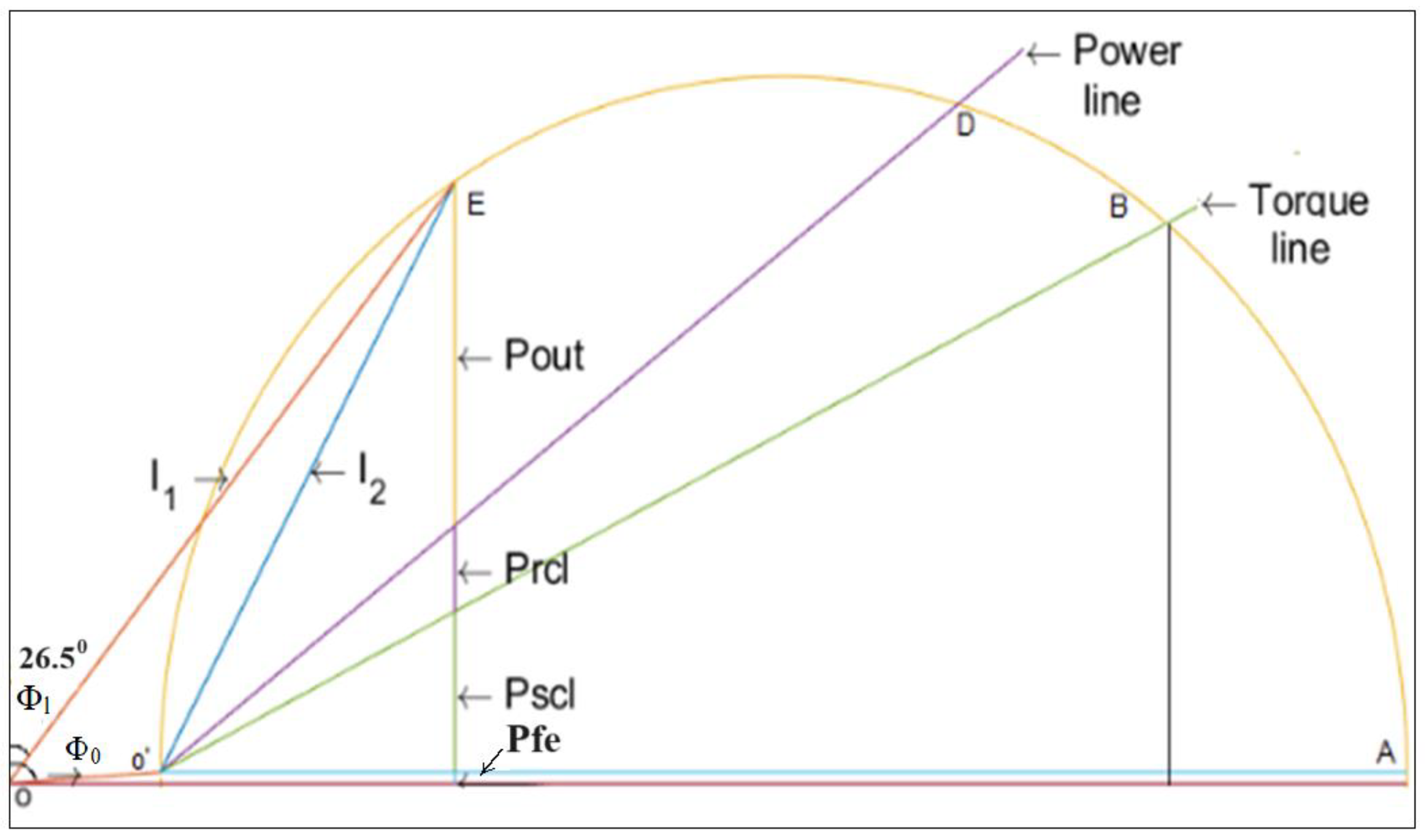
Comparison of results by validation: Induction motor parameters are estimated with the popular methods available in various textbooks and research papers. In this process, a spread sheet program is developed. Also, the circle diagram method is used for validation purposes. The proposed experiment work has been simulated using MATLAB (2022a).
The following standard equations are used to estimate Rc, Xm, and X1:
From the no-load test:
Stator copper loss is estimated with the standard formulae as in Equation (3),
P c s = 3 I 0 2 R 1
Iron loss (Pfe) = no-load power (Po) − stator copper loss (Pcs) − rotational loss (Prot), as in Equation (4), i.e.,
P f e = P o P c s P r o t
Resistance of magnetizing circuit or iron loss (Rc), as in Equation (5),
R c = 3 V p h 2 / P f e
Reactive power at no-load (QNL), as in Equation (6),
Q N L = 3 V N L I N L 2 P N L 2
Reactance (XNL) is as in Equation (7),
X N L = Q N L / ( 3 I N L 2 )
From the short-circuit test:
Short-circuit current at Vn is estimated as in Equation (8),
I L R 2 = I L R 1 ( V n / V L R 1 )
Short-circuit power (PLR2) at Vn is as in Equation (9),
P L R 2 = P L R 1 V n V L R 1 2
Q L R = 3 V L R I L R 2 P L R 2
X L R = Q L R 3 I L R 2
R L R = P L R / ( 3 I L R 2 )
R 2 = ( R L R R 1 ) [ ( X 2 + X m ) / X m ] 2
Also, on obtaining the field test results, estimations are made with the help of various established methods to find out the equivalent circuit parameters of induction motor. From the result comparison, a more accurate method with lowest error is identified. These findings are useful in identifying the best method of parameter estimation which will benefit the users for better speed control of drives at field.

2.4. Other Models

In addition to the equivalent circuit models, it is beneficial to consider the d-q and abc models for a comprehensive understanding of induction motor behavior, especially for control applications.

2.4.1. The d-q Model

The d-q model, also known as the direct-quadrature model, transforms the three-phase stator currents and voltages into two orthogonal components, the direct (d) and quadrature (q) axes, which simplifies the analysis and control of the motor. The d-q transformation equations are given by Equations (14) and (15):
id = ia
i q = 1 3 ( i b i c )
where ia, ib, and ic are the stator phase currents.

2.4.2. The abc Model

The abc model represents the three-phase induction motor in its natural abc reference frame. This model uses the actual phase variables (currents and voltages) and is often used in time-domain simulations. The abc model equations are shown in Equations (16)–(18):
v a = R s i a + d a d t
v a = R s i b + d b d t
v a = R s i c + d c d t
where va, vb, and vc are the stator phase voltages, Rs is the stator resistance, and ψa, ψb, and ψc are the stator flux linkages. By incorporating these models, we can gain deeper insights into the dynamic behavior and control of induction motors, enhancing the precision and effectiveness of vector control strategies.

2.5. Novelty of This Study

This paper presents a novel parameter estimation method that integrates traditional calculation techniques with modern computational tools, validated through rigorous field experiments. Unlike previous studies that rely solely on either theoretical models or limited experimental data, our method combines the strengths of both approaches to enhance accuracy and reduce error margins. We benchmark our proposed method against established methods, including IEEE Standard 112-2017, and demonstrate its superior performance through comprehensive experimental validation.

3. Experimental Setup for Case Study

A case study is presented to demonstrate the effectiveness of the proposed method. One 90 kW/120 HP motor is taken for case study purposes. The estimated motor parameters are then used for vector control of the motor, and the motor performance is evaluated. The IEEE 112:2017 Standard provides a method for determining the performance characteristics of induction motors. The standard, officially known as the IEEE Standard Test Procedure for Polyphase Induction Motors and Generators, provides a comprehensive set of procedures for measuring the performance of induction motors, including the determination of equivalent circuit parameters, efficiency, power factor, and other performance characteristics. The technical specifications of the case study motor are shown in Table 1. The experimental setup is shown in Figure 3. The power quality analyzer used in this experiment is model PQ3100 of Hioki make. The factory test reports are shown in Table 2.
The experimental setup is shown in Figure 3. The power quality analyzer used in this experiment is model PQ3100 of Hioki make. The factory test reports are shown in Table 2.

4. Results and Discussion

The test results and further estimations are described in this section.

4.1. Test Results

4.1.1. DC Resistance of Stator Winding (R1)

The stator is separated from rotor and all the delta winding links are removed. Then, the DC winding resistance is measured at 270 C with a micro-ohm meter. The stator winding resistance is recorded as 0.05963 Ω (phase value of R1).

4.1.2. The No-Load Test

Varying voltage at constant frequency is given to the motor and readings are recorded at no load. The results at various voltages are shown in Table 3 and in Figure 4.

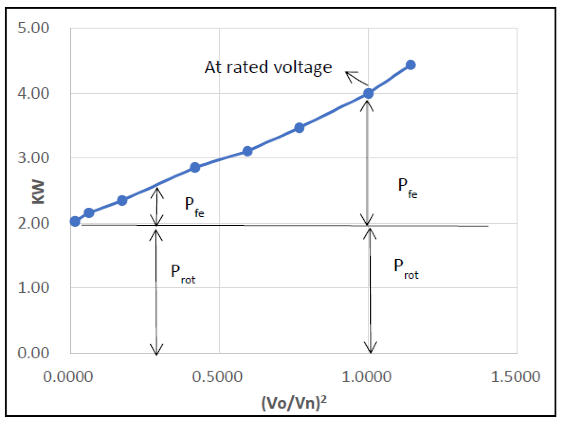
4.1.3. Separation of Core Losses

The core loss consists of iron and rotational losses. The iron loss (Pfe), which varies linearly with voltage, and the rotational loss, i.e., friction and windage loss (Prot), which is constant, are separated as recommended in the IEEE 112: 2017 Standard. The no-load test results are used to calculate other (Vo/Vn)2 components, as shown in Table 4 and in Figure 5. Here, Vo is the applied voltage at no-load, and Vn is the normal rated voltage of the motor. From Figure 4, the rotational loss component is seen as 2 kW, and the rest is the sum of stator copper loss and iron loss, which varies with load and voltage, respectively.
At rated voltage of 415 Volts;
Equations (3)–(13) are used for the following estimates:
Pcs = 0.121 kW
Iron loss (Pfe) = total no-load power − stator copper loss − rotational loss = 4 − 0.121 − 2 = 1.879 kW
Resistance of magnetizing circuit or iron loss (Rc),
Rc = 274.97 Ω
Reactive power at no-load (QNL),
QNL = 32.35 kVAr
Reactance (XNL),
XNL = 15.96 Ω

4.1.4. The Short-Circuit Test

The short-circuit test is conducted on a motor by injecting low voltage, VLR1 (3 phase 75 Volts at 50 Hz) with locked rotor conditions. The current drawn is 160 Amps (ILR1), i.e., the rated current and power consumed is 7.2 kW (PLR1). Estimates are made to determine the short-circuit current (ILR2) at rated voltage (Vn).
Short-circuit current at normal rated voltage (Vn), ILR2 = 160*(415/75) = 885.33 Amps,
Short-circuit power (PLR2) at Vn, PLR2 = 7.2*(415/75)2 = 220.45 kW,
QLR = 19.50 kVAr = 19,500 Var,
XLR = 0.7616 Ω = X1 + X2, now X1 = 0.3047 Ω and X2 = 0.4569 Ω, and
RLR = 0.2813 Ω and R2 = 0.2351 Ω.

4.1.5. The Load Test

A full-load test was conducted on a motor at 415 V, 50 Hz, and recorded power, power factor, and speed, which are 98 kW, 0.88, and 1485 RPM, respectively. These readings confirm the technical specifications given by the manufacturer.

4.2. Comparison with Standard Literature Methods

The following popular methods are prescribed either in textbooks or research papers and are compared in Table 5.
  • In [26] the iron loss component is ignored, and estimates are made for exact equivalent circuit.
  • In [1] the iron loss component is ignored, and estimates are made for exact equivalent circuit.
  • In [27], the author has made calculation for both the approximate and exact equivalent circuits. However, he has ignored R2 in the L-method.
  • In [28], the authors developed an excel spread sheet, which is also developed for this work and shown in Table 6, for easy estimation of parameters.
  • In [29], the author has developed, a MATLAB program for parameter estimation. The steps used in code are given here:
    • Collection of motor name plate data.
    • Estimation of stator current at 50% and 100% loads.
    • Estimation of rotor resistance with the help of above information.
    • Estimation of core resistance by assuming 50% of No-load loss is iron loss.
  • Estimation of rated slip and torque.
  • Estimation of total reactance with the help of starting torque and rated torque.
Parameters estimations are made with the above referred methods and the result are shown in Table 7.
The experimental results show that the method suggested by E. Fitzgerald [1] in their textbook outperforms other methods in terms of accuracy and simplicity. The method is effective in identifying the motor parameters under different operating conditions and varying load torques. This can improve the performance of vector control and reduce the energy consumption of the motor with reduced losses for heating and magnetization. Also, its maximum error is only 6.5% as shown in Table 8.

4.3. Comparison with the Circle Diagram Method

The circle diagram method is the first technique used for parameter estimation of induction motors [30]. It is more complicated and consumes more time with greater chances of resulting in an error due to the adoption of a graph paper and scale. For this work, the circle diagram is drawn as shown in Figure 6. The procedure given in standard literature is used to draw this diagram. From the power line, the line current is estimated to 162 Amps (against the rated current of 160 Amps, i.e., an error of 1.25%) at a power factor of 0.89(against the rated power factor of 0.87, i.e., an error of 2.3%) which are almost meeting the specifications given by the manufacturer. Hence, it is confirmed that the circle diagram method is equally accurate in estimation of induction motor parameters.

4.4. Vector Control of Motor with This Work

Field-Oriented Control (FOC), also known as vector control, is a method for controlling the speed of an induction motor. Use of the vector control technique of motor speed control gives high dynamic performance of the induction motor drive at lower costs [31]. High dynamic performance means high torque response for a given set point of torque reference (a) at the time of starting, i.e., rise time (b) fast settling time (of order of 10–20 ms against that of 200–400 ms in V/f control) of at the time of sudden changes in load torque or changed torque reference point. This, in turn, may result in the motor speed response, also depending on the speed or torque or position control loop used for the induction motor drive and based on the load torque vs. speed characteristics. The goal of vector control is to control the magnetic field generated by the stator winding in such a way as to produce the desired rotor speed very fast.
In vector control, the stator current is resolved into two orthogonal components, the d-axis component, which is aligned with the rotor flux, and the q-axis component, which is orthogonal to the rotor flux. The q-axis component controls the torque produced by the motor, while the d-axis component controls the flux in the motor. Vector control provides several advantages over traditional scalar control methods, such as improved dynamic performance and more accurate speed control. Vector control also allows motors to operate at lower speeds with better accuracy, as it enables control of the magnetic field produced by the motor, which is a key factor in determining the motor’s efficiency by reducing heat producing losses.
The significance of the rotor resistance in a squirrel cage induction motor is that it affects the starting torque of the motor. A higher rotor resistance will result in a higher starting torque and lower efficiency, while a lower rotor resistance will result in a lower starting toque and higher efficiency [32]. The torque–speed curves of the vector control method with above suggested model and the widely used methods are drawn with the help of MATLAB and shown in Figure 7. From the figure also, the suggested method outperforms the other widely used method.
The vector control of the motor using the estimated parameters shows improved performance compared to traditional methods. The motor operates smoothly, with reduced losses for heating and magnetization and improved efficiency. Also, the accuracy of speed control is +0.5% against +1% of that of V/f control [33]. The torque–speed(frequency) curve model of vector control is shown in Figure 8, which shows a smooth constant torque up to rated speed [34].
The V/f control used for induction motor with the suggested method is developed in MATLAB and the output result is shown in Figure 9, in which torque varies with frequency. From this figure, it is clear that the vector control method is helping to obtain a wide range of V/f control with better torque–slip composition.
The proposed parameter estimation method significantly enhances the efficiency of induction motor drives by reducing electrical losses. To quantitatively demonstrate this advantage, we conducted a series of comparative tests measuring the efficiency of motors controlled using both the traditional and our novel parameter estimation methods. For instance, under identical load conditions, our method exhibited a marked improvement in efficiency. Specifically, motors using our parameter estimation approach showed a 2% increase in overall efficiency compared to those using standard estimation methods referenced in our study. This improvement is primarily attributed to more accurate parameter identification, which reduces losses related to incorrect parameter assumptions that can lead to inefficient motor control strategies. Table 9 presents a detailed comparison of efficiency measurements across different methods:

4.5. Benefits to Industry and Environment

This work deals with the exact estimation of parameters of induction motor that are mainly connected with vector-controlled drives for motors operating at lower speeds and requires high accuracy. If the parameters given to drive is more accurate, then the drives give the benefits in the form of accurate control with reduced losses savings which in turn protects the environment.
This work is mainly useful in Industries as follows:
Industrial Automation: In industrial automation and process control, accurate motor parameters are crucial for designing control algorithms that maintain desired performance levels, such as speed, torque, or position, with high precision.
Energy Savings: By accurately predicting induction motor parameters, it becomes easier to identify opportunities for energy savings. Motors can be operated closer to their optimum points, reducing losses and improving overall energy efficiency.
Renewable Energy Systems: Wind turbines and solar tracking systems use induction motors. Accurate predictions of motor parameters aid in optimizing energy capture and converting renewable resources into electricity effectively.
Hence, it can be mentioned that the accurate prediction of induction motor equivalent circuit parameters leads to improved operational efficiency, reduced energy consumption, enhanced equipment reliability, and ultimately, better overall industrial performance.

4.6. Harmonic Effects in Inverter-Supplied Induction Motors

When induction motors are supplied by inverters, the presence of harmonics can significantly affect their performance and the accuracy of the measurements. To illustrate this, a simple circuit model is shown in Figure 10. Here, the sensors are used to find out the voltage, current, speed and harmonics of motor.
The motor under case study is simulated with E-Tap software 22.5 to determine the level of harmonics. The simulation results are shown in Figure 11. Since the drive under study is a 12-pulse drive, the harmonic levels up to 13th harmonic are in order and less than as specified in IEEE 519-2022 (IEEE Standard for Harmonic Control in Electric Power Systems).
The inclusion of harmonics introduces several challenges, such as increased losses, overheating, torque pulsations, reduced power factor and potential resonance issues. These effects can lead to inaccuracies in measurements and overall system performance. By understanding and modeling these effects, future work can focus on developing strategies to mitigate their impact, thereby enhancing the accuracy and reliability of the proposed methodology. Understanding the impact of harmonics on the performance of induction motors is crucial for accurate modeling and reliable operation. Future work will focus on developing strategies to mitigate these harmonic effects, thereby enhancing the accuracy and applicability of the proposed methodology.

5. Conclusions and Future Work

This work highlights a precise parameter estimation technique, enhancing vector control performance, especially at lower speeds, and improving overall drive efficiency. Induction motors are crucial in industrial applications due to their robustness and efficiency. While advancements in vector control demand more precise parameter estimation, traditional methods often fall short in accuracy and computational efficiency. This paper presents a rigorous analysis of parameter estimation techniques, identifying a superior method that integrates traditional and innovative computational techniques. The proposed method benefits predictive maintenance, energy efficiency optimization, and dynamic performance analysis. It aids in motor design, enhances renewable energy systems, and improves the efficiency and reliability of electric vehicle powertrains and HVAC systems. Unlike previous studies relying on theoretical or limited experimental approaches, our work combines robust field experiments with comparative analysis to enhance vector control accuracy. Our novel contribution is an enhanced parameter estimation technique that reduces maximum error to 6.5% from 19.65%, significantly improving dynamic performance, particularly at lower speeds. Additionally, by adhering to and extending IEEE Standard Test Procedure for Polyphase Induction Motors and Generators (IEEE 112-2017, Section 5), our approach meets international standards and sets a new benchmark for accuracy. Future research should focus on deploying the proposed method on hardware to account for dynamic variations in motor parameters caused by operational factors, examining performance under diverse and variable conditions.

Author Contributions

Conceptualization, B.K.R. and V.M.; methodology, B.K.R. and Y.P.K.; validation, B.K.R.; formal analysis, B.K.R., K.S.A. and Y.P.K.; investigation, N.C.G.; resources, P.V.R.; data curation, Y.P.K.; writing—original draft preparation, B.K.R.; writing—review and editing, Y.P.K., N.C.G. and G.F.; visualization, P.V.R.; supervision, N.C.G., P.V.R., G.F. and V.M.; project administration, K.S.A. and V.M. All authors have read and agreed to the published version of the manuscript.

Funding

This research received no external funding.

Informed Consent Statement

Not applicable.

Data Availability Statement

Data used to support the findings of this study are included within this article.

Acknowledgments

This project would not have been possible without the help of M/s EnergiTech Power Insights LLP, which has provided hardware facilities to do the experiments.

Conflicts of Interest

The authors declare no conflicts of interest. However Author Butukuri Koti Reddy was employed by Dept of Atomic Energy, Author Krishna Sandeep Ayyagari was employed by Burns & McDonnel and Author Panganamamula Venkata Rajgopal was employed by Bharat Heavy Electricals Ltd.

References

  1. Fitzgerald, A.E.; Kingsley, C.; Umans, S.D. Electrical Machinery, 6th ed.; McGraw-Hill: New York, NY, USA, 2017. [Google Scholar]
  2. Harakuni, B.; Divatar, B.; Gurram, N.; Sheth, S.; Khaded, R.; Pattar, N. Parameter Estimation and Vector Control of Induction Motor Using Sciamble Workbench. In Proceedings of the IEEE 7th International Conference for Convergence in Technology (I2CT), Pune, India, 7–9 April 2022; pp. 1–6. [Google Scholar] [CrossRef]
  3. Dash, S.; Chakravarty, S.; Giri, N.C.; Ghugar, U.; Fotis, G. Performance Assessment of Different Sustainable Energy Systems Using Multiple-Criteria Decision-Making Model and Self-Organizing Maps. Technologies 2024, 12, 42. [Google Scholar] [CrossRef]
  4. Chunyang, S.; Qinghui, W.; Tao, S.; Haixia, W. Induction Motor Torque Closed-Loop Vector Control System Based on Flux Observation and Harmonic Current Suppression. Control Eng. Pract. 2024, 142, 105755. [Google Scholar] [CrossRef]
  5. Shahin, A.; Elbuluk, M.E.; Toliyat, H.A. Hybrid Neural Network and Grey Wolf Optimization for Online Induction motor parameter estimation. IEEE Trans. Energy Convers. 2021, 36, 1031–1041. [Google Scholar]
  6. Chen, W.; He, J.; Chen, J.; Sun, Y. Adaptive Observer-Based Induction Motor Parameter Estimation Under Time-Varying Disturbances. IEEE Trans. Ind. Electron. 2021, 68, 76–85. [Google Scholar]
  7. Li, L.; Li, C.; Li, Y.; Wang, L. A Novel Online Parameter Identification Algorithm for Induction Motors Based on the Improved Differential Evolution and Multiple Adaptive Kalman Filter. IEEE Access 2020, 8, 21286–21297. [Google Scholar]
  8. Rajput, S.; Bender, E.; Averbukh, M. Simplified Algorithm for Assessment Equivalent Circuit Parameters of Induction Motors. IET Electr. Power Appl. 2020, 14, 426–432. [Google Scholar] [CrossRef]
  9. Abdelwanis, M.I.; Sehiemy, R.A.; Hamida, M.A. Hybrid Optimization Algorithm for Parameter Estimation of Poly-phase Induction Motors with Experimental Verification. Energy AI 2021, 5, 100083. [Google Scholar] [CrossRef]
  10. Ouambo, S.A.T.; Boum, A.T.; Imano, A.M. States and Parameters Estimation for Induction Motors Based on a New Adaptive Moving Horizon Estimation. J. Electr. Comput. Eng. 2022, 2022, 8687025. [Google Scholar] [CrossRef]
  11. Amaral, F.V.; Baccarini, J.M.R.; Coelho, F.C.R.; Baccarini, L.M.R. A High Precision Method for Induction Machine Parameters Estimation from Manufacturer Data. IEEE Trans. Energy Convers. 2020, 36, 1226–1233. [Google Scholar] [CrossRef]
  12. Mahesh, P.; Sabha, R.A.; Rajeev, K.A. An Improved Sliding Mode Observer for Parameter Estimation in Induction Motor Drive with Optimised Gains. Aust. J. Electr. Electron. Eng. 2023, 20, 235–250. [Google Scholar] [CrossRef]
  13. Yoo, J.; Lee, J.; Sul, S.; Baloch, N.A. Stator Resistance Estimation Using DC Injection with Reduced Torque Ripple in Induction Motor Sensorless Drives. IEEE Trans. Ind. Appl. 2020, 56, 3744–3754. [Google Scholar] [CrossRef]
  14. Vukasinovic, J.; Štatkic, S.; Milovanovic, M.; Arsic, N.; Perovic, B. Combined method for the cage induction motor parameters estimation using two-stage PSO algorithm. Electr. Eng. 2023, 105, 2703–2714. [Google Scholar] [CrossRef]
  15. Danin, Z.; Sharma, A.; Averbukh, M.; Meher, A. Improved Moth Flame Optimization Approach for Parameter Estimation of Induction Motor. Energies 2022, 15, 8834. [Google Scholar] [CrossRef]
  16. Rodriguez-Abreo, O.; Rodriguez-Resendiz, J.; Alvarez-Alvarado, J.M.; Garcia-Cerezo, A. Metaheuristic Parameter Identification of Motors Using Dynamic Response Relations. Sensors 2022, 22, 4050. [Google Scholar] [CrossRef] [PubMed]
  17. Stinga, F.; Selisteanu, D. Robust Estimation-Based Control Strategies for Induction Motors. Complexity 2020, 2020, 9235701. [Google Scholar] [CrossRef]
  18. Diab, A.A.Z.; Elsawy, M.A.; Denis, K.A.; Alkhalaf, S.; Ali, Z.M. Artificial Neural Based Speed and Flux Estimators for Induction Machine Drives with Matlab/Simulink. Mathematics 2022, 10, 1348. [Google Scholar] [CrossRef]
  19. Rizk-Allah, R.M.; Abdelwanis, M.I.; El-Sehiemy, R.A.; Abd-Elrazek, A.S. An Interior Search Algorithm Based on Chaotic and Crossover Strategies for Parameter Extraction of Polyphase Induction Machines. Neural Comput. Appl. 2022, 35, 6647–6664. [Google Scholar] [CrossRef]
  20. Sengamalai, U.; Anbazhagan, G.; Thentral, T.M.T.; Vishnuram, P.; Khurshaid, T.; Kamel, S. Three Phase Induction Motor Drive: A Systematic Review on Dynamic Modeling, Parameter Estimation, and Control Schemes. Energies 2022, 15, 8260. [Google Scholar] [CrossRef]
  21. Giri, N.C.; Mohanty, R.C. Turmeric crop farming potential under Agrivoltaic system over open field practice in Odisha, India. Environ. Dev. Sustain. 2024, 1–9. [Google Scholar] [CrossRef]
  22. Choudhary, A.; Mian, T.; Fatima, S.; Panigrahi, B.K. Nature-Inspired Artificial Bee Colony-Based Hyperparameter Optimization of CNN for Anomaly Detection in Induction Motor. Expert Syst. 2024, 41, e13407. [Google Scholar] [CrossRef]
  23. Jain, P.; Singh, B. Parameter Estimation of Induction Motor for Vector Control: A Review. IEEE Trans. Energy Convers. 2018, 33, 268–278. [Google Scholar]
  24. Aziz, A.G.M.A.; Abdelaziz, A.Y.; Ali, Z.M.; Diab, A.A.Z. A Comprehensive Examination of Vector-Controlled Induction Motor Drive Techniques. Energies 2023, 16, 2854. [Google Scholar] [CrossRef]
  25. IEEE Standard 112-2017; IEEE Standard Test Procedure for Polyphase Induction Motors and Generators. IEEE: New York, NY, USA, 2017.
  26. Chapman, S.J. Electrical Machinery and Power System Fundamentals, 5th ed.; McGraw-Hill: New York, NY USA, 2012. [Google Scholar]
  27. Mashar, A. Determination of Three-Phase Induction Motor Equivalent Circuit Parameters Experimentally. IEEE Trans. Ind. Appl. 2013, 49, 2531–2539. [Google Scholar]
  28. Natarajan, R.; Misra, V. Parameter Estimation of Induction Motors Using a Spreadsheet Program on a Personal Computer. Electr. Power Syst. Res. 1989, 16, 157–164. [Google Scholar] [CrossRef]
  29. Haque, M. Determination of NEMA Design Induction Motor Parameters from Manufacturer Data. IEEE Trans. Energy Convers. 2008, 23, 997–1004. [Google Scholar] [CrossRef]
  30. Al-Jufout, S.A.; Al-Rousan, W.H.; Wang, C. Optimization of Induction Motor Equivalent Circuit Parameter Estimation Based on Manufacturer’s Data. Energies 2018, 11, 1792. [Google Scholar] [CrossRef]
  31. Salomon, C.; Sant’Ana, W.; Lambert-Torres, G.; Borges da Silva, L.; Bonaldi, E.; de Oliveira, L. Comparison Among Methods for Induction Motor Low-Intrusive Efficiency Evaluation Including a New AGT Approach with a Modified Stator Resistance. Energies 2018, 11, 691. [Google Scholar] [CrossRef]
  32. Ghosh, S. MATLAB Simulation of Circle Diagram in Three Phase Induction Motor. IETE J. Educ. 2022, 63, 63–77. [Google Scholar] [CrossRef]
  33. Agrawal, K.C. Electrical Power Engineering Reference & Applications Handbook, 6th ed.; Elsevier: Amsterdam, The Netherlands, 2020. [Google Scholar]
  34. Hu, J.; Jia, M.; Xiao, F.; Fu, C.; Zheng, L. Motor Vector Control Based on Speed-Torque-Current Map. Appl. Sci. 2020, 10, 78. [Google Scholar] [CrossRef]
Figure 1. Work flowchart.
Technologies 12 00123 g001
Figure 2. Induction motor equivalent circuits: (a) approximate equivalent circuit, and (b) exact equivalent circuit.
Technologies 12 00123 g002
Figure 3. Experimental setup with motor under test: (a) Motor under test with power quality analyzer, (b) stator alone, and (c) rotor alone.
Technologies 12 00123 g003aTechnologies 12 00123 g003b
Figure 4. No-load test results.
Technologies 12 00123 g004
Figure 5. Separation of core loss.
Technologies 12 00123 g005
Figure 6. Circle diagram for the case study motor.
Technologies 12 00123 g006
Figure 7. Torque–speed curves of suggested model and other model.
Technologies 12 00123 g007
Figure 8. Torque–speed curve of the vector control method.
Technologies 12 00123 g008
Figure 9. V/f control of IM with the suggested method.
Technologies 12 00123 g009
Figure 10. Motor with drive for measurements.
Technologies 12 00123 g010
Figure 11. Voltage harmonic spectrum.
Technologies 12 00123 g011
Table 1. Technical specifications of the case study motor.
S. No.ParameterValue
1Power output90 KW (120 HP)
2Number of phases and connection3 & Delta
3Rated voltage415 Volts
4Type of induction motorSquirrel-cage
5Rated current160 Amps
6Efficiency at full load91.56%
7Power factor at full load0.87
8Normal speed1485 RPM
9NEMA codeB
10Rated torque (Tr)594 N-m
11Starting torque (Tm)1070 N-m
Table 2. Factory test reports of a 90 kW/120 HP motor.
Type of TestVoltage
(Volts)
Frequency
(Hz)
Current
(Amperes)
Speed
(RPM)
Total Power
(kW)
No-load415504514954
Short-circuit (tested)75501600.007.2
Short-circuit (calculated)41550889.20.00105.4
Full load415501601483100.8
Table 3. No-load test results.
Voltage
(Volts)
Frequency
(Hz)
Current
(A)
Active Power, P(kW)Apparent Power, S
(kVA)
Reactive Power, Q
(kVAr)
Power Factor
(Cos Ø-lag)
52.00 50.00 81.00 2.03 7.24 6.94 0.29
104.00 50.00 16.20 2.16 2.81 1.79 0.77
173.00 50.00 18.00 2.35 5.01 4.50 0.46
268.47 50.00 22.00 2.86 11.20 10.80 0.25
320.00 50.00 30.00 3.11 16.61 16.36 0.19
363.73 50.00 37.00 3.47 21.84 22.11 0.15
415.00 50.00 45.00 4.00 32.00 32.40 0.12
443.41 50.00 52.00 4.44 40.25 40.05 0.11
Table 4. Separation of core loss.
Voltage (Vo)
(Volts)
(Vo/Vn)2No-Load Power P0 (kW)Prot
(kW)
Pfe
(kW)
52.000.022.032.000.03
104.000.062.162.000.16
173.000.172.352.000.35
268.470.422.862.000.86
320.000.593.112.001.11
363.730.773.472.001.47
415.001.004.002.002.00
443.411.144.442.002.44
Table 5. Comparison of popular methods.
ReferenceMethodFindingsLimitations
[26]Approximate circuit calculationR1, R2, X1, X2 and XmIron loss component is ignored.
[1]Approximate circuit calculationR1, R2, X1, X2 and XmIron loss component is ignored.
[27]L-ModelR2 is ignored Approx. equiv. circuit is used.
[27]T-ModelR1, R2, X1, X2 and XmExact equivalent circuit is used.
[28]Spread sheetAssumed that the Iron loss and rotational losses are equalNil.
[29]MATLAB code Nil.
Table 6. Excel spreadsheet model for parameter estimation.
Name Plate DataEstimates
S. No.DescriptionSymbol
(Unit)
ValueS. NoDescriptionSymbol
(Unit)
Estimated Value
1Shaft Output powerHP1201Input phase voltageVph (Volts)415.
2Input Line VoltageVL (volts)4152Synchronous speedNs (RPM)1500
3Supply FrequencyF(Hz)503Rated slipSr0.0100
4Rated Current at Full loadIr
(Amps)
1604Total resistance (stator + rotor)Rt (Ohms)0.0445
5Number of PolesP45Constant loss (core + stray + fri. and windage)PK (Watts)4138.1881
6NEMA Motor classA, B, C or DB6Magnetizing resistance (core loss is 50% of const. loss)Rm (Ohms)249.7107
7Rated efficiencyEffr0.91567No-load active currentIor (Amps)1.6619
8Efficiency at 75% loadEff 0.750.90688Rated Pf angleOr (Radians)0.5156
9Current at 75% loadI 0.75
(Amps)
126.009Pf angle at 75% loadO 0.75 (Radians)0.5355
10Rated Power factor at full loadPfr0.8710Ir SinΦʎ (Amps)58.3649
11Power factor at 75% loadPf 0.750.8611Magnetizing currentIm (Amps)20.5234
12Rated speed at full loadN
(RPM)
148512Magnetizing reactance per phaseXm (Ohms)20.2209
13Starting torque to FL torque ratioTs
(=%Tr)
18013Work componentᴪ (Amps)137.7541
14Maximum torque to FL torque ratioTm
(=%Tr)
25014Rotor current per phase ref. to statorI2′ (Amps)149.6084
15ConnectionDelta or StarDelta15Rotor power factorPf20.9208
NEMA Design Motors empirical relation for leakage reactance16Rotor resistance per phase ref. to statorR2′ (Ohm)0.0135
ClassX1X2X1/X217Stator resistance per ph.R1 (Ohm)0.0310
A0.50.5118Start. to Max torque ratioA (Amp)0.7200
B0.40.60.66719Work component 1 (for estimation purpose)Β (Amps)0.6940
C0.30.70.42920Work component 2 (for estimation purpose)ꭇ (Amps)0.4250
D0.50.5121Rotor leakage reac. per phase referred to statorX2′ (Ohms)0.0317
22Stator leakage reac. per ph.X1 (Ohm)0.0211
Table 7. Comparison of results.
Parameter
(Ω)
Method 1 Field ExperimentsMethod 2 [27]Method 3 [1]Method 4 (L-Model) [28]Method 5 (T-Model) [28]Method 6 [29]Method 7 [30]The Best Method w.r.t. Field Test (Number)
R10.059630.059630.059630.059630.059630.059630.0963All methods except 7
R20.23510.28130.2351Ignored0.2830.01350.01353
Rc274.97IgnoredIgnored274.83260.5225.18175.314
X10.30470.2850.2850.28740.2740.02110.2162, 3
X20.45690.47630.4750.47910.45620.03170.3233
Xm15.6615.68415.5659.239.2217.0217.402, 3
Table 8. Results comparison with best performing method.
Parameter (Ω)Field ExperimentsE. Fitzgerald & Co (Textbook) [1]Error [%]
R10.059630.059630
R20.23510.23510
Rc274.97Ignored-
X10.30470.2856.50
X20.45690.47503.96
Table 9. Efficiency comparison.
MethodEfficiency at 50% LoadEfficiency at Full LoadNotes
Baseline Method (Traditional)87.5%89.3%Based on empirical equations
Proposed Method
(This Study)
89.0%91.3%Utilizes advanced computational techniques for parameters estimation
Disclaimer/Publisher’s Note: The statements, opinions and data contained in all publications are solely those of the individual author(s) and contributor(s) and not of MDPI and/or the editor(s). MDPI and/or the editor(s) disclaim responsibility for any injury to people or property resulting from any ideas, methods, instructions or products referred to in the content.

