Article

Characterization of Commercial and Custom-Made Printing Filament Materials for Computed Tomography Imaging of Radiological Phantoms

1
Morphé, Praxitelous 1, 54641 Thessaloniki, Greece
2
Department of Medical Equipment, Electronic and Information Technologies in Healthcare, Medical University of Varna, 9002 Varna, Bulgaria
3
Medical College, Medical University of Varna, 9002 Varna, Bulgaria
4
Dipartimento di Fisica “Ettore Pancini”, Università di Napoli Federico II, I-80126 Napoli, Italy
*
Author to whom correspondence should be addressed.
Technologies 2024, 12(8), 139; https://doi.org/10.3390/technologies12080139
Submission received: 9 May 2024 / Revised: 1 August 2024 / Accepted: 16 August 2024 / Published: 20 August 2024
(This article belongs to the Special Issue 3D Printing Technologies II)

Abstract

:
In recent years, material extrusion-based additive manufacturing, particularly fused filament fabrication (FFF), has gained significant attention due to its versatility and cost-effectiveness in producing complex geometries. This paper presents the characterization of seven novel materials for FFF and twenty-two commercially available filaments in terms of X-ray computed tomography (CT) numbers, as tissue mimicking materials for the realization of 3D printed radiological phantoms. Two technical approaches, by 3D printing of cube samples and by producing cylinders of melted materials, are used for achieving this goal. Results showed that the CT numbers, given in Hounsfield unit (HU), of all the samples depended on the beam kilovoltage (kV). The CT numbers ranged from +411 HU to +3071 HU (at 80 kV), from −422 HU to +3071 HU (at 100 kV), and from −442 HU to +3070 HU (at 120 kV). Several commercial and custom-made filaments demonstrated suitability for substituting soft and hard human tissues, for realization of 3D printed phantoms with FFF in CT imaging. For breast imaging, an anthropomorphic phantom with two filaments could be fabricated using ABS-C (conductive acrylonitrile butadiene styrene) as a substitute for breast adipose tissue, and ASA-A (acrylic styrene acrylonitrile) for glandular breast tissue.

1. Introduction

Three-dimensional printing technology, also referred to as additive manufacturing, has found extensive utilization in various industries and medical applications [1,2,3]. This includes the production of prostheses [4], implants [5], radiological phantoms [6], and 3D printed scaffolds for tissue regeneration to enhance tissue repair and growth [7,8]. Additionally, it has contributed to the development of biomedical devices utilizing advanced stimuli-responsive polymers [9].
In the field of X-ray imaging, anthropomorphic phantoms with equivalent radiological properties serve as valuable assets across numerous applications, allowing the replication of X-ray attributes of human tissues and the evaluation of diverse medical imaging methods and technologies. Specifically, 3D printed phantoms can be utilized for dose validation [5,10], medical imaging device settings optimization [11], surgery planning [12], and quality assurance and optimization of imaging techniques [13,14,15,16].
The fidelity of replicating human anatomy for X-ray imaging applications through 3D printing technology is closely linked to the X-ray characteristics of the materials used. To be suitable for the fabrication of phantoms for X-ray imaging, the most important property of a candidate material is its appropriate X-ray attenuation characteristics [13]. Consequently, significant efforts are focused on determining the X-ray properties of these materials to accurately replicate human tissues [17,18,19,20,21,22,23]. Various materials have been investigated to manufacture tissue-equivalent phantoms mimicking human organs such as the thyroid gland [24], breast [13], and thorax [25]. Among the technologies used for these phantoms are the photo-curing technologies. However, they have inherent limitations, as they are restricted to materials that can undergo polymerization when exposed to light [26,27]. Another limitation is that the resins used in photo-curing often experience shrinkage during the curing process [28]. This occurs because the photopolymerization reaction generates heat, causing the material to expand and then contract as it cools. This can lead to warping, dimensional inaccuracies, and internal stresses in the printed objects. Additionally, the mechanical properties of photo-cured resins, such as toughness and impact resistance, are generally lower compared to thermoplastics used in fused filament fabrication (FFF) [29]. Finally, printed parts often require extensive post-processing, including washing in solvents to remove uncured resin and additional UV curing to ensure complete polymerization [27,30]. This increases time, complexity, and potential health hazards in the overall process. The same limitation also pertains to phantoms created using radiopaque inks and paper [31,32,33].
On the contrary, when it comes to radiological phantoms created through the deposition of molten plastic filaments using the FFF technique, it becomes feasible to develop materials exhibiting a diverse range of compositions. Replicating lung and bone tissues poses a significant challenge, as it requires achieving both exceptionally low and high electron densities. Consequently, not all technologies and methodologies can effectively emulate such demanding conditions. Moreover, X-ray images of anthropomorphic phantoms with incorporated tumor models revealed a clear need for further investigation of suitable tissue mimicking materials for 3D printing. This is because the visibility of the tumors differed significantly from what is observed in clinical cases, indicating the necessity for additional research in this area [34].
During the past decade, many commercial and in-house developed materials have been investigated for FFF-based printers for use in radiological applications. These studies have focused on the X-ray attenuation coefficients at specific tube voltages or X-ray photon energies, as well as their elemental composition [18,22,24,35]. Additionally, the Hounsfield unit (HU) values of these materials have been examined in computed tomography (CT) images [36,37]. Among these materials are PLA-stone (polylactic acid filled with powdered stone), PLA-wood (polylactic acid filled with grinded wood powder), PETG (polyethylene terephthalate glycol), ASA (acrylonitrile styrene acrylate), and HIPS (high impact polystyrene), as shown by Ma et al. [37]. The authors demonstrated that PLA-stone is particularly suitable for mimicking hard tissues, such as bone. PLA-wood can be used for mimicking soft tissues, although the exact HU values and suitability for specific tissues require further study. PETG-based materials exhibit a wide range of HU values and are adaptable for various tissue types, depending on their specific formulations and the inclusion of fillers like carbon fibers. ASA is suitable for mimicking water and some soft tissues, while HIPS closely mimics adipose tissue. Further studies on other commercial materials are needed to identify more suitable options, especially when using printing with two filaments to ensure compatibility in printing temperature and material properties. Our initial experimentation with HIPS and ASA revealed significant challenges in printing phantoms from these two materials. Moreover, from the investigation of 25 commercial filaments for FFF 3D printing, Ma et al. [37] showed that in most polymer filaments, the HUs increase significantly compared to the HUs of soft tissues, which vary minimally. This is attributed to the insufficient effective atomic number of the available printing materials, resulting in a CT number increase with harder beams [20]. The study also found that the PLA-Al (PLA matrix reinforced with aluminum) filament maintains a nearly consistent HU value across all measured spectra. However, this filament is suitable for reproducing soft tissues only when printed with a lower filling factor, controlled by the printing software. Dancewicz’s study [36] investigated the CT values of samples with air gaps within printed inserts made from ABS, standard PLA, photoluminescent PLA, woodfill, bronzefill, and copperfill plastic filaments, with infill densities ranging from 10% to 90%. However, the study did not evaluate samples with 100% infill density.
This study was motivated by ongoing research aimed at addressing the limitations in the availability of materials suitable for FFF 3D printing, especifically for reproducing soft tissues such as glands and tumors [38]. The long-term goal of the research team is to identify materials suitable for producing radiological breast phantoms that can be utilized across a wide range of anode tube voltages (kV). Therefore, there is a need for novel materials, as commercial products, while generally possessing good overall qualities, may not meet the specific requirements for medical imaging applications. Three specific objectives of this work were set: (a) to investigate average CT numbers (in Hounsfield units, HU) of 22 commercial and 7 newly fabricated materials and observe how these values change with different applied kV settings during CT scans; (b) to compare the results with existing data in the literature to determine their suitability for the production of radiological phantoms; and (c) to study whether 100% infill printed samples exhibit different CT values compared to materials prepared in casted forms, considering that 3D printing can introduce air voids affecting HU measurements.
For this purpose, filaments of the selected materials were printed into cubic samples and melted for comparison. HU measurements were conducted using a clinical CT scanner operating at 80 kV, 100 kV, and 120 kV with a fixed slice thickness. This approach allows for a comprehensive assessment of the materials’ performance and ensures that the findings are robust and applicable to practical medical imaging scenarios.

2. Materials and Methods

This research involved the fabrication of 7 custom-made materials and the selection of 22 commercially available materials, a total of 29 filament materials, adopted for FFF 3D printing. All the materials were printed with a Longer LK4 Pro printer into cubes with dimensions 20 mm × 20 mm × 10 mm. A part of each filament was grinded into pellets, placed into metallic cylinder container, and then heated up to their melting points to receive a homogeneous cylindrical sample of this material. The cubes and the cylindrical samples were scanned at a clinical CT scanner at three anode voltages and a slice thickness of 0.6 mm.

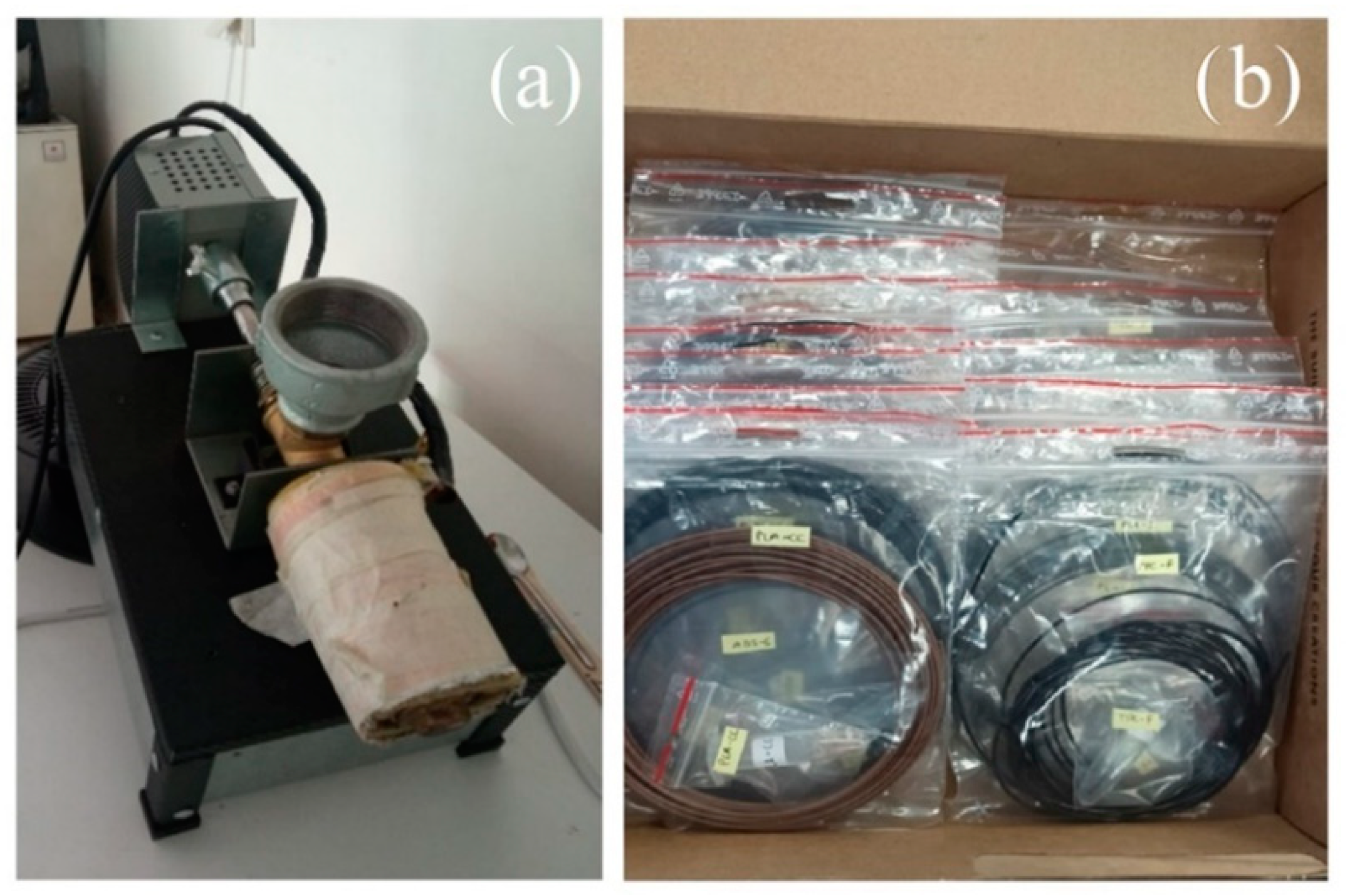
2.1. Filament Fabrication

A composite filament consists of two main components, the binder and the filler. The binder could be a common thermoplastic polymer such as acrylonitrile butadiene styrene (ABS) or polylactic acid (PLA), while the filler could be various external substances such as special stone, wood, metallic particles, nanoparticles, etc. ABS has been used extensively as a binder due to its long polymer chain, allowing external particles to be easily attached, compared to PLA, which presents a short polymer chain. The fabrication of anthropomorphic phantoms requires materials suitable for replicating both soft and hard tissues, which should present appropriate X-ray characteristics [37,39,40,41,42]. Regarding the replication of soft tissues, ABS and PLA have been found to be suitable [17,18,43]. Additionally, PLA or ABS can be mixed with other external materials for HU simulation of bone tissues, such as acrylonitrile butadiene styrene (ABS) combined with barium sulfate [44], ferromagnetic polylactic acid (PLA) combined with regular density PLA (i.e., standard PLA) [45], or PLA with gravimetric powdered stone [46]. The choice of PLA and ABS in this study is further supported by their favorable mechanical properties, ease of processing, availability, and versatility in forming composites. These qualities make them ideal candidates for developing accurate and reliable 3D printed phantoms for medical imaging applications.
To obtain novel polymer-based filament materials, a total of 7 custom-made materials, derived from ABS and PLA, were fabricated using various fillers. The filament production began by mixing the binder (in pellet form) and the filler (in powder form). The filaments were manually cut using a cutter, and a grinder was employed when necessary. Cesium sulfate, cement, silica gel, gypsum, and barium sulfate were utilized as fillers. A high-accuracy scale was used to measure the weight of the initial mixture (binder and filler). A single screw extruder was then used to fabricate the filaments (Figure 1a). The initial mixture was inserted into the extruder through the hopper, and a single screw pushed the mixture towards the heated nozzle of the filament maker until a filament with a 1.75 mm diameter was extruded. The newly produced filament was cut into pellets and repeatedly inserted into the extruder at least three times to increase the homogeneity of the final filament. The same temperature used for printing the cubes was also used for the filament maker. The particular filament maker has a single speed (3D-tech, Thessaloniki, Greece).
The chosen commercial materials, including PLA-based and ABS-based filaments, have densities that closely resemble those of various human tissues. The objective was to explore a wide range of filaments available on the market with densities similar to those of human tissues. Figure 1b shows samples of both custom-made and commercial filaments, while Table 1 provides the specifications of each material.

2.2. Cubes and Cylindrical Samples

Filaments from all the selected materials were printed into cubic samples with dimensions of 20 mm × 20 mm × 10 mm (as seen in Figure 2b) using a 3D printer LK4 Pro (Longer3D, Shenzhen, Guangdong, China) and the Ultimaker Cura slicing software (Ultimaker, Utrecht, The Netherlands). The nozzle had a diameter of 0.6 mm; the infill density was 100%; and the thickness of each printed layer was 0.25 mm. Additionally, Ultimaker Cura’s linear infill pattern was used for printing each material. Table 2 summarizes the printing parameters and the furnace temperatures used for each printed cube and cylindrical sample. The infill pattern used was a linear pattern set at a 90-degree angle.
Furthermore, a part of each filament was cut into pellets at the Medical University—Varna, placed in a metallic cylinder container with a height of 35 mm, an inner diameter of 15 mm, and an outer diameter of 21 mm, and heated in a furnace at various temperatures close to their melting point to produce a cohort of samples that did not go through the printing process. A single cylindrical melted sample is shown in Figure 2c.
The purpose of producing samples by both casting and 3D printing was to thoroughly investigate the differences in HUs between the two fabrication methods. This approach allows for a comprehensive comparison to determine how the presence of air voids, which are commonly introduced during the 3D printing process, affects the overall HU measurements. By using casting, we can create solid samples without the risk of air voids, providing a baseline for the HU values of each material. This comparison is crucial, as air voids in 3D printed samples can lead to inaccuracies in HU measurements, thereby affecting the reliability and precision of the radiological phantoms.

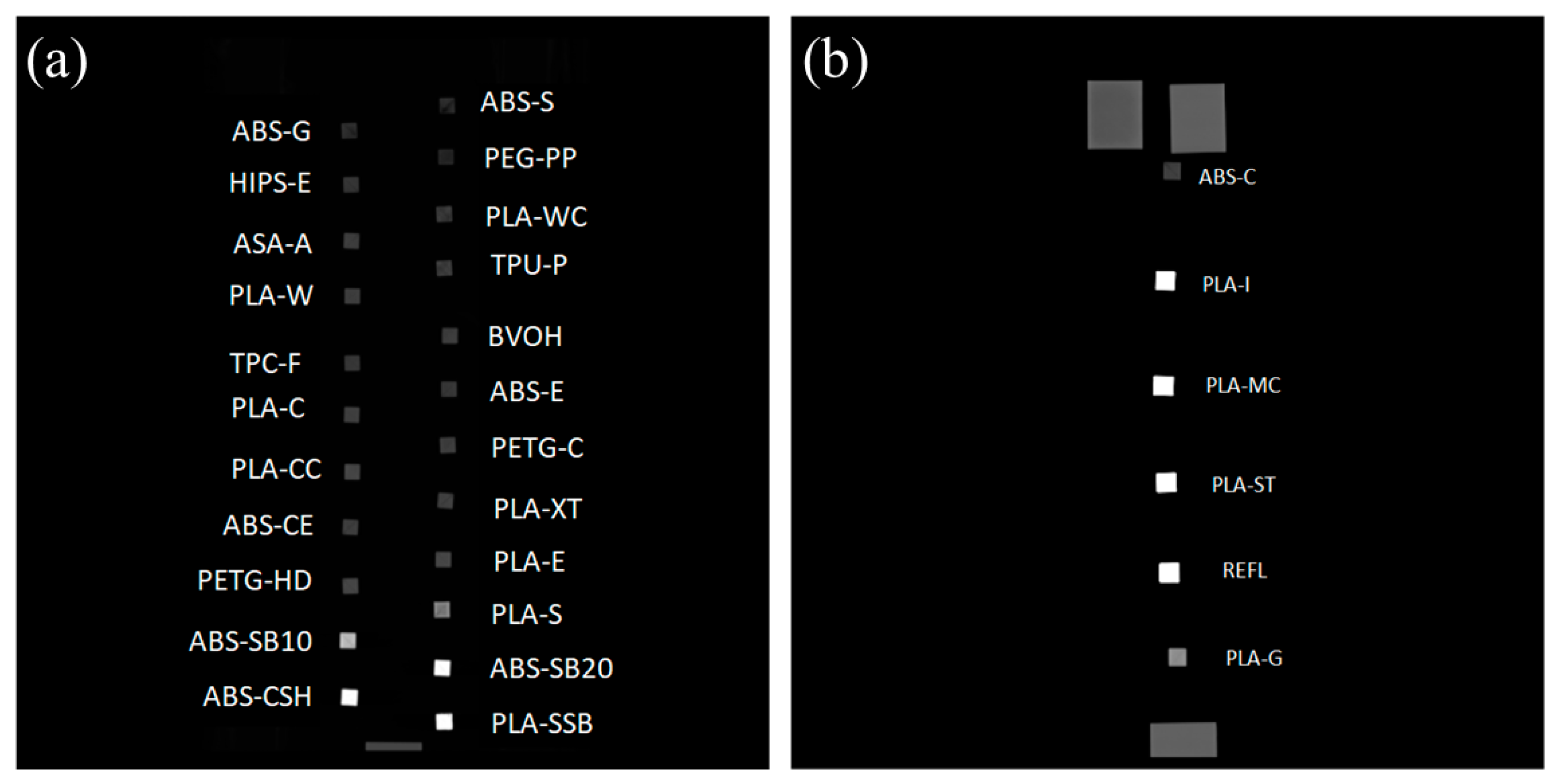
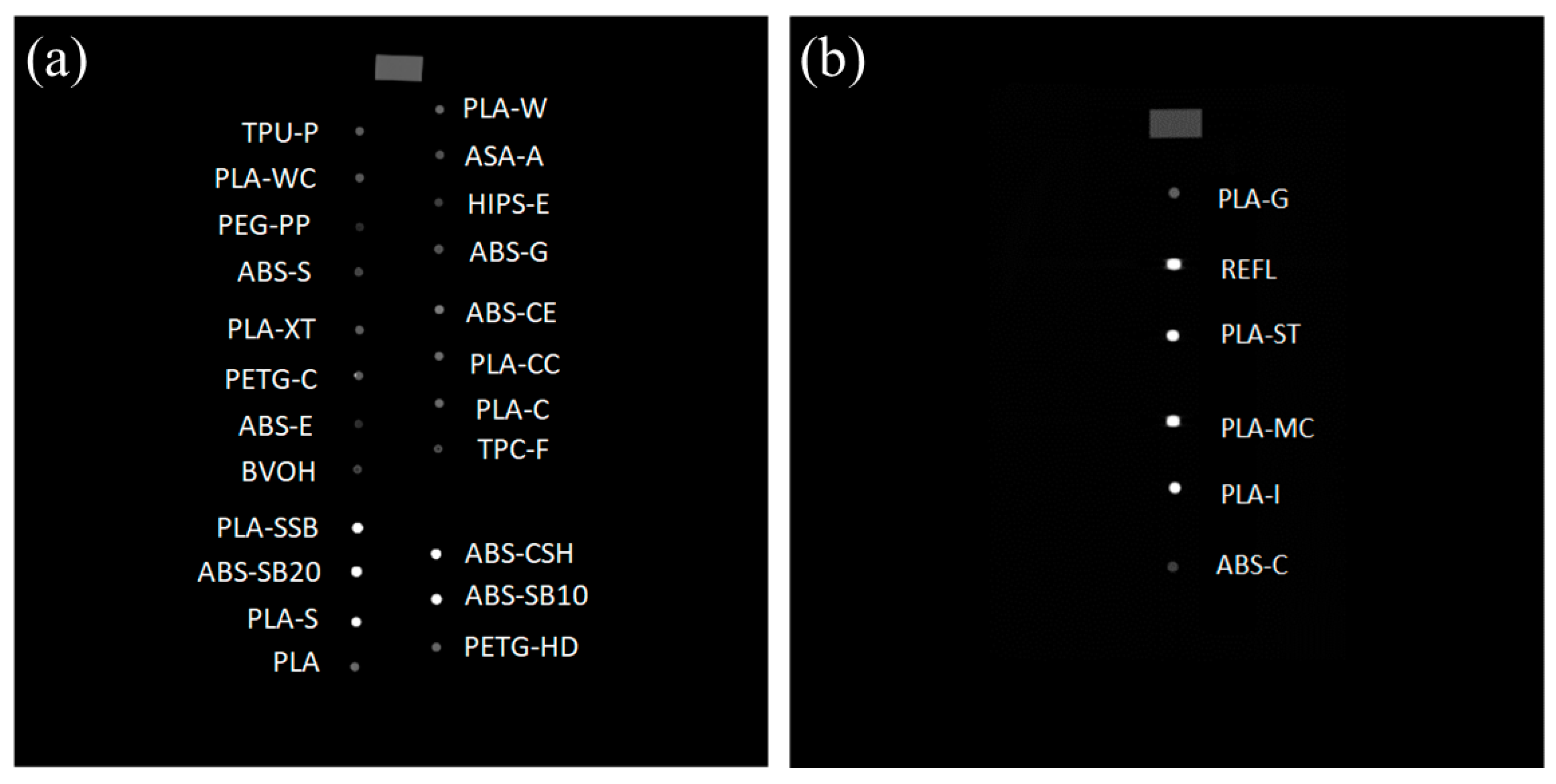
2.3. Computed Tomography (CT) Scans of Twenty-Nine 3D Printed and Melted Samples

The printed cubic samples and the cylindrical pellet (melted) samples were CT scanned at Saint Marina University Hospital of Varna using a Siemens SOMATOM Definition scanner (Figure 2a). They were divided into two groups. The first group (Figure 3a,b) included all the materials without metallic components (ABS-S, ABS-G, PEG-PP, PLA-WC, ASA-A, TPU-P, TPC-F, BVOH, PLA-C, ABS-E, PLA-CC, PETG-C, PLA-CC, PLA-XT, ABS-CE, PLA-E, PETG-HD, PLA-S, ABS-SB10, ABS-SB20, ABS-CSH, PLA-SSB). The second group of samples (Figure 4a,b) included all the materials with metallic components (PLA-I, PLA-MC, ABS-C, PLA-G, PLA-ST, REFL).
The materials were divided in this manner and placed across each other in different directions to prevent saturation effects. The cubic (printed) and cylindrical (melted) samples were scanned with a CT scanner using a modified abdomen protocol at three planes: 80 kV, 100 kV, and 120 kV, with a 0.6 mm slice thickness. The nominal range of CT numbers for the scanner was −1024 HU (minimum) to +3092 HU (maximum).

2.4. Hounsfield Units Measurements

The freeware ImageJ (Version 1.52a, free Java image processing program, USA) was utilized for measuring the HUs of each sample [47]. The 80 kV, 100 kV, and 120 kV CT scans of each plane—coronal, axial, and sagittal—were employed for the investigation of the HUs of each material, with each slice having a thickness of 0.6 mm. The mean HU value, the standard deviation (STD), and the minimum and maximum HU values were evaluated in a volume of interest consisting of 7 slices (4.2 mm thickness) in the middle of the cubic or cylindrical samples, within a selected region of interest (ROI) with area ranging from 40 mm2 to 120 mm2, depending on the sample size in the CT scan.

3. Results

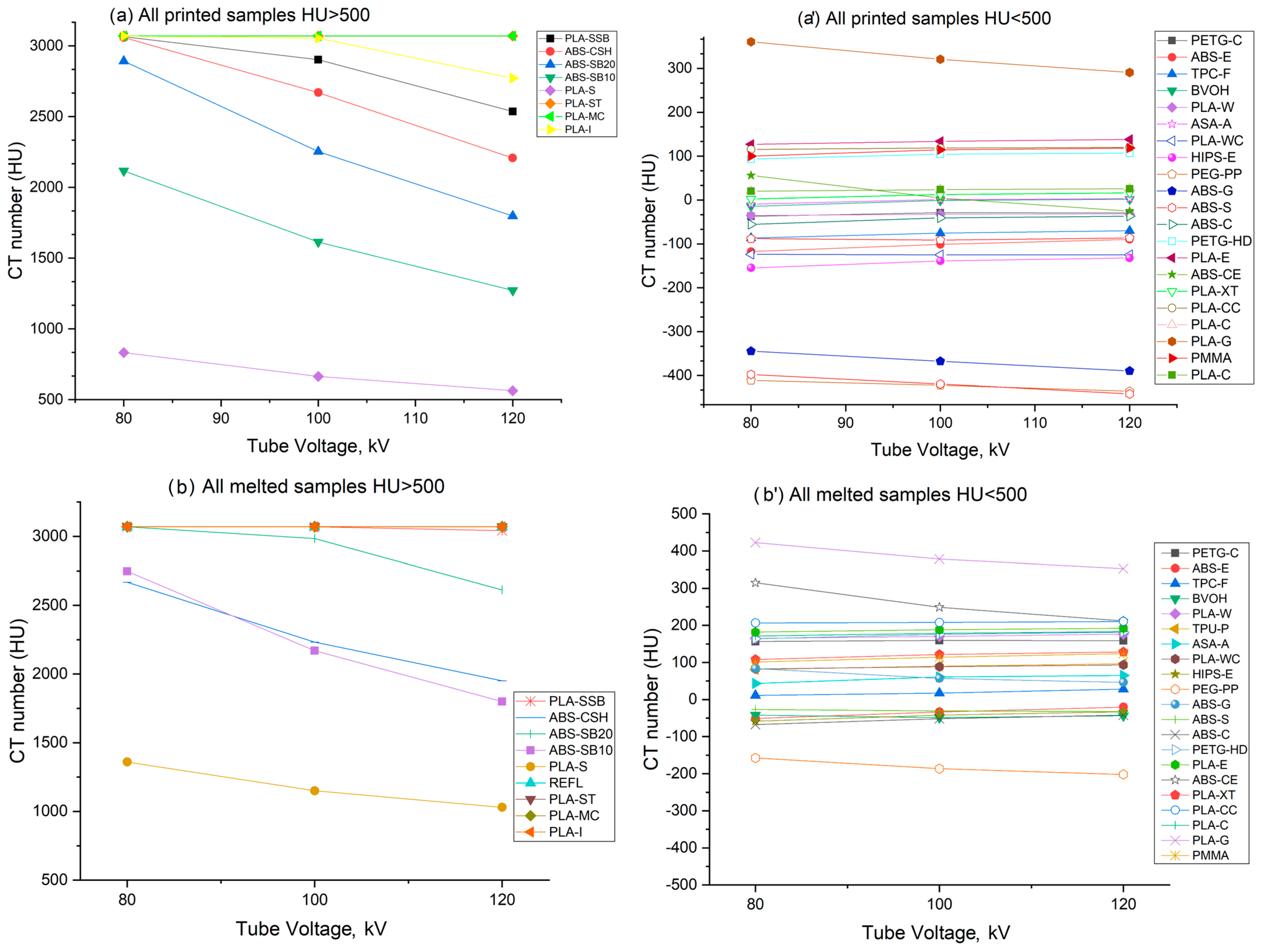
3.1. Measured Hounsfield Units

Figure 5 shows the CT numbers of all the printed (Figure 5a) and melted samples (Figure 5b); values for a PMMA block scanned under the same conditions are shown for reference. For all samples, the average CT numbers (±STD) ranged from −411 ± 4 HU to +3071 ± 0.1 HU (at 80 kV), from −422 ± 4 HU to +3071 ± 0.1 HU (at 100 kV), and from −442 ± 39 HU to +3070 ± 0.1 HU (at 120 kV). After scanning the PMMA block sample twice, its average CT number was between +118 HU to +124 HU at 120 kV, and from +100 HU to +101 HU at 100 kV, in agreement with literature data [48].
Figure 5a includes materials containing metallic particles (PLA-I, PLA-MC, PLA-ST) and reflective particles (REFL); these samples show average CT values saturated at +3071 HU. For an accurate determination of their average CT number, a 16-bit CT scanner should be employed, as their attenuation is likely above +3071 HU. For non-metallic and non-reflective materials, Figure 5 shows that at 120 kV, the printed samples exhibit CT numbers ranging from −442 ± 38 HU (for ABS-S) to +2536 ± 8 HU (for PLA-SSB). For melted samples, at 120 kV, CT numbers are in the range from −201 ± 7 HU (for PEG-PP) to +3042 ± 15 HU (for PLA-SSB). Data for all non-metallic and non-reflective samples are shown in Table A1 in the Appendix A section.

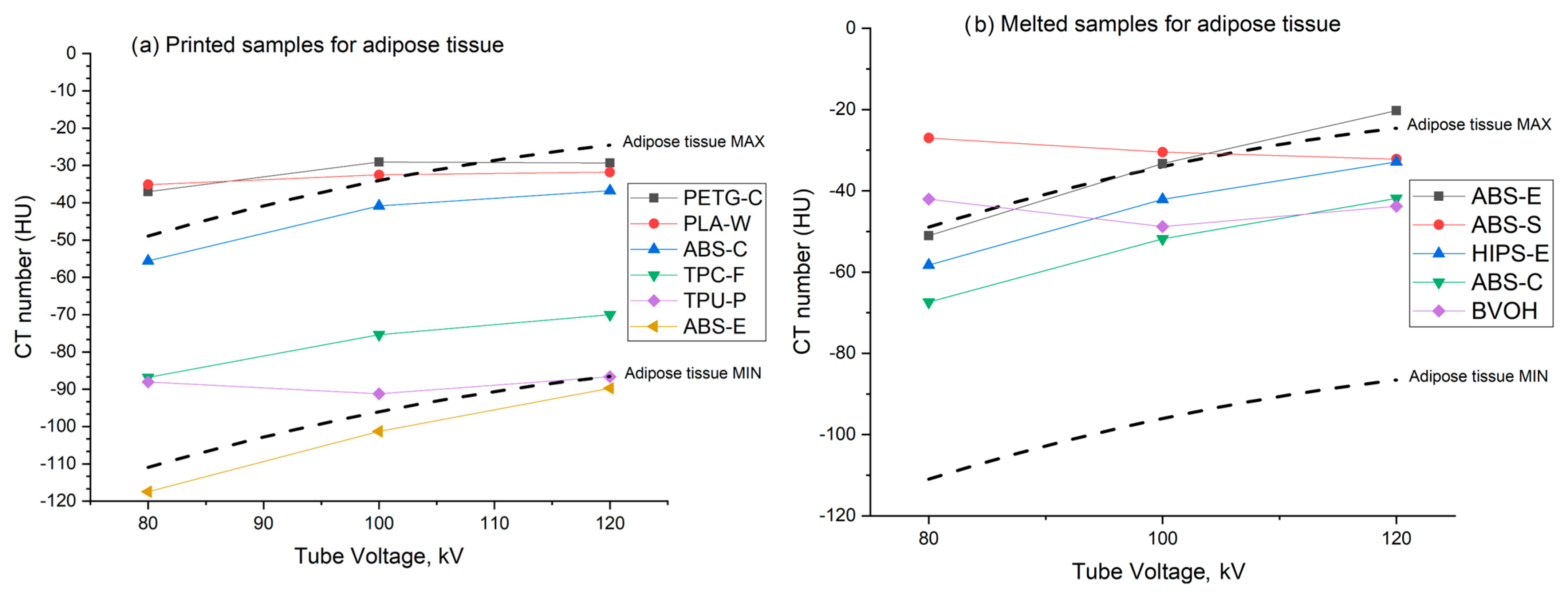
3.2. Adipose Tissue Mimicking Materials

For melted samples, at 120 kV, Figure 6 shows that HIPS-E, ABS-E, ABS-C, ABS-S and BVOH, are suitable materials for mimicking adipose tissue, with average CT numbers of—32 ± 2 HU, −20 ± 4 HU, −41 ± 12 HU, −32 ± 2 HU, and −43 ± 24 HU, respectively. For 3D printed samples at 120 kV, ABS-E, ABS-C, PLA-W, TPU-P, and TPC-F suitably mimic adipose tissue. The CT numbers of all these materials were within the range of minimum/maximum HU values for adipose tissue of bovine and porcine samples, as reported by Ma et al. [20].

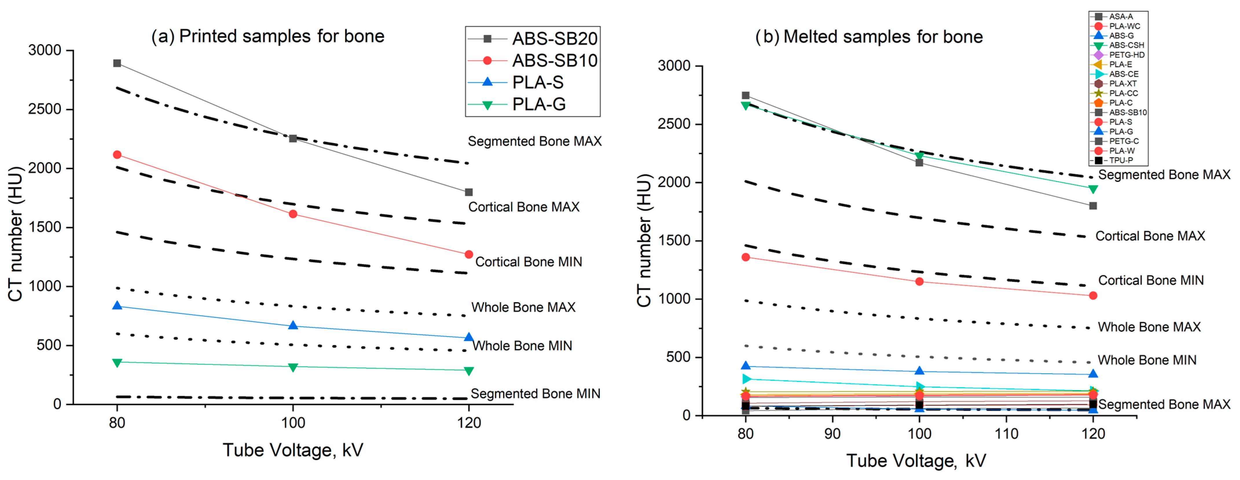
3.3. Bone Tissue Mimicking Materials

The CT numbers of the scanned materials are compared in Figure 7 with the range of minimum and maximum HU values for bone segmented in regions of varying hardness, as well as whole and cortical tissues from bovine and porcine samples, as reported by Ma et al. [20].
For printed samples at 120 kV, it was found that ABS-SB10 is a suitable material for mimicking cortical bone, with an average CT number of +1272 ± 5 HU. PLA-S, which has slightly lower attenuation than the minimum required for cortical bone, mimics whole bone, with an average CT number of +563 ± 11 HU. For bone tissue segmented from animal CT scans [20], which exhibit CT numbers ranging from +50 HU to +2042 HU, our data for 3D printed samples at 120 kV showed that ABS-SB20, ABS-SB10, PLA-S, and PLA-G are suitable substitutes for segmented bone tissue samples.
For melted samples at 120 kV, no material was found to be suitable for mimicking cortical bone or whole bone. However, for bone tissue segmented from animal CT scans [20], with CT numbers ranging from +50 HU to +2042 HU, our data for 3D printed samples at 120 kV showed that PETG-C, PLA-W, TPU-P, ASA-A, PLA-WC, ABS-G, ABS-CSH, ABS-SB10, PLA-S, PETG-HD, PLA-E, ABS-CE, PLA-XT, PLA-CC, PLA-C, and PLA-G are suitable substitutes for segmented bone tissue samples.

3.4. Soft Tissue Mimicking Materials

For printed samples at 120 kV, no material is suitable for mimicking soft tissue, which requires an average CT number within the range of +50 HU to +80 HU, as indicated in Ma et al. [20]. For melted samples at 120 kV, ASA-A is a suitable substitute for soft tissue, with an average CT number of +65 ± 8 HU. Additionally, TPU-P and TPC-F show CT numbers adequate for representing some soft tissues, such as glandular tissue (+40 HU) [49]; these materials exhibit a small increase in HUs with the increase in kV: from +81 HU to +96 HU (TPU-P) and from +11 HU to +28 HU (TPC-F).

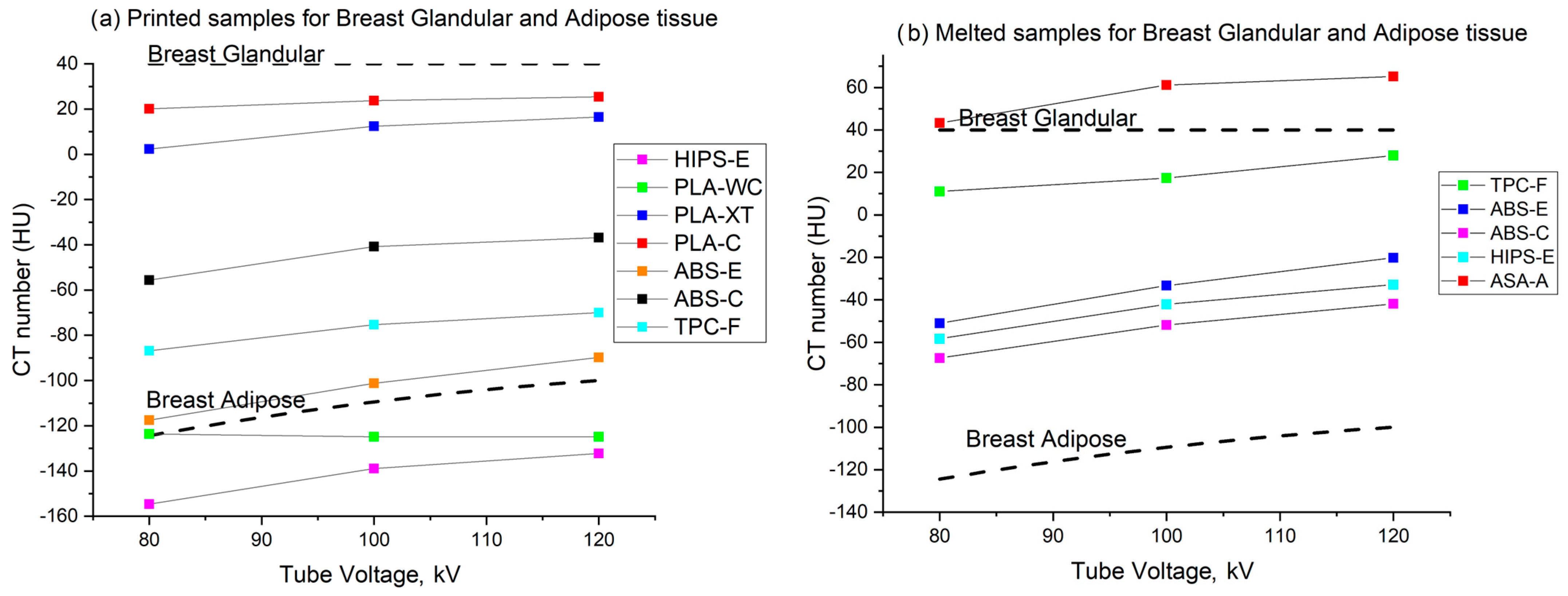
3.5. Breast Tissue Mimicking Materials

Figure 8a shows that for mimicking breast tissues (adipose and glandular), the choice for printed samples narrows down to PLA-C or PLA-XT for glandular tissue, and PLA-WC, HIPS-E, TPC-F, or ABS-C for adipose tissue. Figure 8b shows that TPC-F and ASA-A can mimic breast glandular tissue for melted samples, but no melted sample was found as a suitable substitute for breast adipose tissue. At 120 kV, we measured an average CT number of +25 ± 1 HU for PLA-C, +16 ± 6 HU for PLA-XT, +124 ± 12 HU for PLA-WC, and +132 ± 2 HU for HIPS-E in printed samples. For melted samples, TPC-F and ASA-A showed average CT numbers of +28 ± 31 HU and +65 ± 8 HU, respectively.

4. Discussion

In this study, a total of 29 materials were investigated for their radiation characteristics, including seven custom-made materials and 22 commercially available materials. PMMA was used as a reference material. These materials are considered by the research group of the PHENOMENO project (www.phenomeno.eu) as candidates for replicating breast and bone tissues. This work builds on previous studies by other groups [20,37] as well as our own group [6,18,22,50,51,52] on 3D printed anthropomorphic phantoms based on FFF 3D printing, by extending the fabrication and analysis to new filament materials. These include TPC-F, BVOH, various ABS-based filaments filled with high-density materials, as well as new PLA filaments like PLA-XT (Table 1), which were custom-made for this study and have not been characterized previously.
Furthermore, a novel approach was employed to enhance the accuracy of CT number measurements when analyzing 3D printing materials. This was accomplished through a melting procedure, which eliminated air voids by melting the filaments in pellet form in a furnace at their corresponding melting temperatures. Previous researchers utilized a plastic container filled with water to mount the 3D printed samples for HU measurements [20,37], while others mounted the printed samples in a standard Gammex phantom (Gammex RMI, Middleton, WI, USA) [53]. Although this approach yielded comparable results to our melting process, the primary concern with FFF remains the presence of small air-filled voids in the 3D printed phantoms, which influence the material’s CT number assessment.
Indeed, the HUs measured on the printed and melted samples ranged from −442 HU to +2535 HU and from −201 HU to +3041 HU, respectively, at 120 kV, for samples without metallic and reflective fillers. The decrease in CT number from melted samples to 3D printed samples is attributed to the presence of embedded air in the printed samples, which can be partially regulated by suitable 3D printing manufacturing procedures, as suggested by Ma et al. [37]. These authors used the equivalence of the density of the filaments and corresponding 3D printed objects as a criterion for deciding the ‘quality’ of the printing procedure to avoid air voids in the phantoms. However, there is no standard or widespread procedure in FFF 3D printing for achieving this goal. Kozee et al. [53] suggested varying the infill angle by 10 degrees with each layer when printing. To avoid air voids in printing filaments, pre-extrusion techniques, such as subjecting the polymer material to an oven at around 75 °C for a few hours before printing, effectively eliminate any lingering moisture [54]. The obtained information of this comparison between the two approaches is essential for accurately defining the X-ray characteristics of the filaments and fine-tuning the 3D printing process to produce precise phantoms. In the future, this will be extremely helpful for simulating the X-ray characteristics under various scenarios.
Typically, CT scans utilize a tube potential of 120 kV. Table 3 provides a summary of which materials are suitable for mimicking specific tissues in radiological phantoms, along with their corresponding HU values. When bone tissue is considered, the HU can vary based on the specific type of bone, its composition, and its location within the body. As a general range, compact or cortical bone typically falls between +700 and +3000 HU. In contrast, trabecular or cancellous bone, which is less dense and has a spongier structure, usually falls within the range of +200 to +1000 HU [20,55]. For adipose tissue, data varied approximately between −39 HU and −100 HU at 120 kV [20,55,56,57]. Soft tissue HU values range between 4 HU and 80 HU [55]. Normal mammary gland tissue was measured at 28.7 HU on CT images [55].
For breast tissue, data presented by Ruschin et al. [49] indicate values around 40 HU at 120 kV. Yang et al. [57] measured HU values for 100% glandular tissue and 50/50 glandular/adipose tissue to be approximately 46 HU and −35 HU, respectively. Data from non-contrast CT scans show that HU values for fibroadenomas range from 32 to 43 HU, while hamartomas average 52 HU [58]. Cystic breast nodules have HU values averaging between 13 and 27 HU [58]. Studies indicate that, in general, benign lesions have attenuation less than 20 HU [59,60]. Specifically, Desperito et al. [60] reported that benign masses measured at 22 HU, while average cancer masses measured at 49 HU. Similar data provided by Urata et al. [61] show tumor HU values to be 69 ± 30.65 HU. Wienbeck et al. [62] confirmed these findings, showing that the mean CT density of analyzed lesions in clinically non-contrast breast CT scans was 63.95 ± 38.18 HU, with a range of 2.86 to 160.75 HU.
As discussed by Ma et al. [20], for most printing materials, regardless of the printing technology used, the Hounsfield value increases with increasing beam hardness. This is due to the lower effective atomic number of these materials Zeff than that of water and soft tissues, with the exception of adipose tissue. This leads to a relative increase in Compton scattering as beam hardness increases; thus, in higher HU values for these materials at a higher kV. Future work will involve experimentally investigating the elemental composition of the samples and their relationship to the Hounsfield values. Preliminary results in this field have already been obtained [63].
In any case, a validation and calibration process should be carefully performed for printed phantoms to ensure they reflect the required HU values of tissues. Our group is working on a new technology for filament-based 3D printing of anthropomorphic phantoms using a single filament and a variable extrusion rate at each printing position, along with new printing patterns. This technology will eventually permit the fabrication of anthropomorphic human body phantoms from a single filament material with good CT number accuracy, as shown by Dukov et al. [64,65] for anthropomorphic breast phantoms that mimic adipose and fibroglandular tissues.
The availability of several materials with different HUs (either commercially available or custom-made) can be exploited in printing anthropomorphic phantoms simulating largely different types of tissue, like low-atomic number soft tissues and high-density cortical bone tissue, even including metal body implants. The assessment of their radiopacity is a necessary step for X-ray imaging or dosimetry applications.
The average CT number of the metallic filaments (PLA-MC, PLA-I, PLA-ST) should decrease with the increase in beam energy, similar to the results of Kozee et al. [53] and Ma et al. [37]. This is due to the high atomic number filler, such as iron, which produces a predominant photoelectric effect at lower energies. Our custom-made metallic filaments have CT numbers exceeding the maximum range of our 12-bit scanner, with only printed PLA-I showing a slight decrease in HU values at increasing kV values. Research in materials with high atomic numbers is important for bone applications, such as preparing bone planes [66], as well as producing anthropomorphic bone phantoms for radiological purposes [50,67]. This study showed that the addition of high atomic number elements to PLA and ABS materials leads to a decrease in HUs with increasing beam hardness. Specifically, materials such as PLA-G and PLA-S (stone) demonstrate a clear trend of decreasing HUs as the kV value increases, as shown by Ma et al. [37] for some of these materials. These materials are highly suitable for applications involving whole or compact bones, where HUs typically range from +400 HU at higher energies (140 kV) to +1200 HU at energies of 70 kV, as reported by Ma et al. [20].
The HUs of the adipose tissue varied approximately from −130 HU to −60 HU at 70 kV, and from −90 HU to −20 HU at 140 kV [20]. Among the studied ABS melted samples, ABS-E and ABS-C show values within the range of adipose HUs, with a slight increase in HUs from 80 kV to 120 kV, similar to that of adipose tissue. HIPS-E attenuation is −32 ± 2 HU at 120 kV. All these filaments can be used to replicate adipose tissue in the given kV range. At 120 kV, ABS-S shows −32 ± 2 HU, and BVOH has −43 ± 24 HU, thus falling within the range for mimicking adipose tissue. However, the trend in the CT number versus beam kV for ABS-S and BVOH does not increase as expected for adipose tissue, unlike the other materials (ABS-E, ABS-C, HIPS-E). Hence, ABS-S and BVOH are considered unsuitable for making an adipose tissue phantom.
Ma et al. [20] reported HUs for soft tissues ranging from +50 HU to +90 HU for beams ranging from 70 kV to 140 kV, as the HU for a given soft tissue remains relatively constant with kV. Among the studied materials, ASA-A, TPU-P, and TPC-F may be adequate for representing some soft tissues due to their small increase in HUs with the increase in kV. For example, for liver tissue, the CT number is between +50 HU and +70 HU, with ASA-A being a possible substitute, while for kidney tissue, the CT number is between +20 HU and +40 HU, with TPC-F being a possible substitute [68]. TPC-F corresponds to muscle tissue with an HU of +28 ± 31 HU [69]. TPU-P and TPC-F materials exhibit easy printing properties, with printing temperatures of 220–250 °C and 220–260 °C, respectively.
Additionally, these materials have some unique features: TPU-P does not warp or deform during the printing and cooling process, and it is a hygroscopic material that attracts and holds water molecules from the surrounding environment. On the other hand, TPC-F has 43% renewable bio-based content, excellent UV resistance, and high impact resistance. The cost for both materials is higher than the fundamental materials, at 37.50 € per 500 g.
The ideal tissue mimicking phantom should be made from materials that exhibit HU values similar to those of human tissue at commonly used diagnostic beam energies in CT, when printed with 100% infill density. Here, we also consider the case of a breast phantom and a bone phantom, when searching for suitable tissue mimicking materials. In the case of the breast phantom, Varallo et al. [70] reported on printed 3D breast anthropomorphic phantoms from segmented breast CT scans. The FFF 3D printing was realized with ABS to mimic adipose tissue and PLA or PET to mimic glandular tissue and skin. However, at CT energies, these materials exhibited CT numbers (+24 HU and +188 HU at 100 kV) higher than those for adipose and glandular tissues, respectively.
For the possible realization of an anthropomorphic breast phantom with two filaments for two tissue components (adipose and glandular), a solution provided by our study consists of ABS-C (for breast adipose tissue) and ASA-A (for glandular breast tissue). According to our measurements (Table A1), the contrast between the two breast tissues is +110 HU at 80 kV, +112 HU at 100 kV, and +106 HU at 120 kV, i.e., almost constant with beam energy in the explored range. This is compatible with the approximate CT number contrast of +140 HU between breast adipose tissue (-100 HU) and breast fibroglandular tissue (+40 HU), as assumed in recent studies [49,71].
When bone tissue is considered, the Hounsfield units can vary based on the specific type of bone, its composition, and its location within the body. As a general range, compact or cortical bone typically falls between +300 HU and +3000 HU. On the other hand, trabecular or cancellous bone, which is less dense and has a spongy structure, usually falls within the range of +200 HU to +1000 HU [20]. Kozee et al. [53] reported that StoneFil (used in our PLA-S filament), which contains a higher atomic number calcium component, offers the potential to replicate the physical densities associated with different bone types and the atomic number relevant to photoelectric interactions. Our study also showed that PLA-S is a suitable material for bone phantoms.
The emphasis on CT numbers in our study aligns with the specific requirements of developing accurate and effective radiological phantoms. While other properties, such as mechanical strength and biocompatibility are also important, our primary objective was to ensure that the phantoms accurately mimic the radiological characteristics of human tissues for improved imaging. Future work may involve a more comprehensive assessment of these factors to broaden the application of the developed materials.

5. Conclusions

In this study, a total of 29 materials were investigated for their radiation characteristics, including seven custom-made materials and 22 commercially selected materials for FFF 3D printing, which were scanned at a clinical CT unit using three different beam energies. The results showed that HUs of melted and printed samples differ, as the melted samples demonstrated higher CT numbers due to the absence of void gaps typically found in printed samples, even with a 100% infill factor. We identified several commercial and custom-made filaments that are suitable for substituting both soft and hard human tissues. In the special case of breast imaging, the possible realization of an anthropomorphic breast phantom with two filaments is envisaged, consisting of ABS-C for breast adipose tissue and ASA-A for glandular breast tissue, suitable for all CT energies.

Author Contributions

Conceptualization, N.O. and K.B.; methodology, N.O. and K.B.; software, F.O.; formal analysis, F.O.; investigation, all authors; resources, N.O., N.D., M.M. and Z.B.; data curation, F.O.; writing—original draft preparation, F.O., K.B. and P.R.; writing—review and editing, all; visualization, F.O. and P.R.; supervision, N.O., K.B. and P.R.; project administration, Z.B.; funding acquisition, K.B. All authors have read and agreed to the published version of the manuscript.

Funding

The PHENOMENO project “Physical breast anthropomorphic models and technology for their production” has received funding from the European Union’s HORIZON 2020 research and innovation program under the Marie Skłodowska-Curie grant agreement No 101008020.

Institutional Review Board Statement

Not applicable.

Informed Consent Statement

Not applicable.

Data Availability Statement

All imaging data on which the results are based are available at Zenodo 10.5281/zenodo.11160211.

Conflicts of Interest

Author Filippos Okkalidis, Chrysoula Chatzigeorgiou, and Nikiforos Okkalidis were employed by the company Morphé. The remaining authors declare that the research was conducted in the absence of any commercial or financial relationships that could be construed as a potential conflict of interest.

Appendix A

The printed cubic samples and the cylindrical pellet (melted) samples were CT scanned at Saint Marina University Hospital of Varna using a Siemens SOMATOM Definition scanner. They were divided into two groups. Figure A1a and Figure A2a show the first group, which included all the materials without metallic components (ABS-S, ABS-G, PEG-PP, PLA-WC, ASA-A, TPU-P, TPC-F, BVOH, PLA-C, ABS-E, PLA-CC, PETG-C, PLA-CC, PLA-XT, ABS-CE, PLA-E, PETG-HD, PLA-S, ABS-SB10, ABS-SB20, ABS-CSH, PLA-SSB). The second group of samples (Figure A1b and Figure A2b) included all the materials with metallic components (PLA-I, PLA-MC, ABS-C, PLA-G, PLA-ST, REFL). A referenced cube of polymethyl methacrylate (PMMA) (the large, unlabeled rectangular shapes in the figures) has been placed into both groups.
Figure A1. Arrangements of the scanned cube samples. (a) Coronal plane of CT scan with 23 printed cubes at 80 kV. (b) Coronal plane of CT scan with 6 printed cubes at 80 kV.
Technologies 12 00139 g0a1
Figure A2. Arrangements of the cylindrical samples. (a) Coronal plane of CT scan with 23 cylindrical samples at 80 kV. (b) Coronal plane of CT scan with 6 cylindrical samples at 80 kV.
Technologies 12 00139 g0a2
Data for all non-metallic and non-reflective samples are summarized in Table A1.
Table A1. Measured CT numbers (in Hounsfield units) of printed and melted samples. For comparison, we repeated the evaluations for PMMA samples, resulting in the following HUs: 100 (80 kV), 110 (100 kV), and 118 (120 kV). Data for samples containing metallic particles (PLA-MC, PLA-I and PLA-ST) or reflective particles (REFL) are not included in the table; their average HU values reached the maximum value for our CT scanner.
PETG-HDPETG-CPLA-EPLA-CC
kVprintedmeltedprintedmeltedprintedmeltedprintedmelted
80+93 ± 3+163 ± 3−37 ± 3+156 ± 39+127 ± 2+181 ± 3+115 ± 3+206 ± 2
100+104 ± 2+175 ± 2−29 ± 4+159 ± 31+133 ± 1+188 ± 4+118 ± 4+207 ± 2
120+106 ± 2+181 ± 3−29 ± 3+158 ± 2+138 ± 1+192 ± 2+119 ± 4+210 ± 2
PLA-CPLA-WPLA-WCPLA-G
kVprintedmeltedprintedmeltedprintedmeltedprintedmelted
80+20 ± 3+171 ± 2−35 ± 1+165 ± 3−123 ± 10+82 ± 5+360 ± 1+422 ± 5
100+23 ± 2+178 ± 1−32 ± 1+170 ± 3−124 ± 13+88 ± 6+320 ± 2+378 ± 5
120+25 ± 1+183 ± 2−31 ± 1+176 ± 6−124 ± 12+93 ± 5+290 ± 2+353 ± 4
PLA-XTABS-CEABS-EABS-G
kVprintedmeltedprintedmeltedprintedmeltedprintedmelted
80+2 ± 4+108 ± 5+55 ± 3+315 ± 3−117 ± 2−51 ± 4−344 ± 6+83 ± 6
100+12 ± 5+121 ± 4+4 ± 3+248 ± 3−101 ± 1−33 ± 3−367 ± 5+57 ± 7
120+16 ± 6+128 ± 5-25 ± 3+212 ± 3−89 ± 2−20 ± 4−389 ± 8+46 ± 6
ABS-SABS-CTPC-FBVOH
kVprintedmeltedPrintedmeltedprintedmeltedprintedmelted
80−397 ± 37−27 ± 3−55 ± 2−67 ± 12−86 ± 211 ± 30−14 ± 6−42 ± 24
100−419 ± 35−30 ± 3−40 ± 4−51 ± 12−75 ± 317 ± 32−1 ± 6−48 ± 25
120−442 ± 38−32 ± 2−36 ± 4−41 ± 12−70 ± 428 ± 311 ± 5−43 ± 24
TPU-PASA-AHIPS-EPEG-PP
kVprintedmeltedPrintedmeltedprintedmeltedprintedmelted
80−88 ± 8+81 ± 9−9 ± 1+43 ± 8−154 ± 4−58 ± 1−410 ± 4−157 ± 6
100−91 ± 7+90 ± 90 ± 2+61 ± 7−138 ± 3−42 ± 2−422 ± 4−186 ± 6
120−86 ± 7+96 ± 10+3 ± 1+65 ± 8−132 ± 2−32 ± 2−435 ± 4−201 ± 7
PLA-SSBABS-CSHABS-SB10ABS-SB20
kVprintedmeltedprintedmeltedprintedmeltedprintedmelted
80+3065 ± 4+3071 ± 0.1+3059 ± 6+2668 ± 52+2117 ± 10+2748 ± 38+2893 ± 5+3070 ± 1
100+2902 ± 34+3069 ± 4+2670 ± 28+2232 ± 57+1614 ± 6+2171 ± 30+2253 ± 5+2985 ± 16
120+2536 ± 8+3042 ± 15+2208 ± 46+1951 ± 52+1272 ± 5+1800 ± 28+1798 ± 8+2612 ± 30
PLA-S
kVprintedmelted
80+832 ± 13+1360 ± 14
100+664 ± 12+1151 ± 12
120+563 ± 11+1030 ± 2

References

  1. Ballard, D.H.; Trace, A.P.; Ali, S.; Hodgdon, T.; Zygmont, M.E.; DeBenedectis, C.M.; Smith, S.E.; Richardson, M.L.; Patel, M.J.; Decker, S.J.; et al. Clinical Applications of 3D Printing: Primer for Radiologists. Acad. Radiol. 2018, 25, 52–65. [Google Scholar] [CrossRef] [PubMed]
  2. Durfee, W.K.; Iaizzo, P.A. Chapter 21—Medical Applications of 3D Printing. In Engineering in Medicine; Iaizzo, P.A., Ed.; Academic Press: Cambridge, MA, USA, 2019; pp. 527–543. [Google Scholar]
  3. Yan, Q.; Dong, H.; Su, J.; Han, J.; Song, B.; Wei, Q.; Shi, Y. A Review of 3D Printing Technology for Medical Applications. Engineering 2018, 4, 729–742. [Google Scholar] [CrossRef]
  4. Manero, A.; Smith, P.; Sparkman, J.; Dombrowski, M.; Courbin, D.; Kester, A.; Womack, I.; Chi, A. Implementation of 3D Printing Technology in the Field of Prosthetics: Past, Present, and Future. Int. J. Environ. Res. Public Health 2019, 16, 1641. [Google Scholar] [CrossRef] [PubMed]
  5. Goodall, S.K.; Rampant, P.; Smith, W.; Waterhouse, D.; Rowshanfarzad, P.; Ebert, M.A. Investigation of the effects of spinal surgical implants on radiotherapy dosimetry: A study of 3D printed phantoms. Med. Phys. 2021, 48, 4586–4597. [Google Scholar] [CrossRef]
  6. Okkalidis, N. 3D printing methods for radiological anthropomorphic phantoms. Phys. Med. Biol. 2022, 67, 15TR04. [Google Scholar] [CrossRef]
  7. Placone, J.K.; Engler, A.J. Recent Advances in Extrusion-Based 3D Printing for Biomedical Applications. Adv. Healthc. Mater. 2018, 7, e1701161. [Google Scholar] [CrossRef]
  8. Tümer, E.H.; ErbilTümer, E.H.; Erbil, H.Y. Extrusion-Based 3D Printing Applications of PLA Composites: A Review. Coatings 2021, 11, 390. [Google Scholar] [CrossRef]
  9. Tariq, A.; Arif, Z.U.; Khalid, M.Y.; Hossain, M.; Rasool, P.I.; Umer, R.; RamakrishnaTariq, A.; Arif, Z.U.; Khalid, M.Y.; Hossain, M.; et al. Recent Advances in the Additive Manufacturing of Stimuli-Responsive Soft Polymers. Adv. Eng. Mater. 2023, 25, 2301074. [Google Scholar] [CrossRef]
  10. Robinson, A.P.; Tipping, J.; Cullen, D.M.; Hamilton, D.; Brown, R.; Flynn, A.; Oldfield, C.; Page, E.; Price, E.; Smith Robinson, A.P.; et al. Organ-specific SPECT activity calibration using 3D printed phantoms for molecular radiotherapy dosimetry. EJNMMI Phys. 2016, 3, 12. [Google Scholar] [CrossRef]
  11. Frandon, J.; Akessoul, P.; Hamard, A.; Bezandry, E.; Loffroy, R.; Addala, T.; Bertrand, M.M.; Beregi, J.-P.; GreffierFrandon, J.; Akessoul, P.; et al. Comparison of acquisition and iterative reconstruction parameters in abdominal computed tomography-guided procedures: A phantom study. Quant. Imaging Med. Surg. 2021, 12, 281–291. [Google Scholar] [CrossRef]
  12. Kettenbach, J.; Kara, L.; Toporek, G.; Fuerst, M.; Kronreif, G. A robotic needle-positioning and guidance system for CT-guided puncture: Ex vivo results. Minim. Invasive Ther. Allied Technol. 2014, 23, 271–278. [Google Scholar] [CrossRef] [PubMed]
  13. Bliznakova, K. The advent of anthropomorphic three-dimensional breast phantoms for X-ray imaging. Phys. Medica 2020, 79, 145–161. [Google Scholar] [CrossRef] [PubMed]
  14. Holmes, R.B.; Negus, I.S.; Wiltshire, S.J.; Thorne, G.C.; Young, P.; Alzheimer’s Disease Neuroimaging Initiative. Creation of an anthropomorphic CT head phantom for verification of image segmentation. Med. Phys. 2020, 47, 2380–2391. [Google Scholar] [CrossRef]
  15. Gear, J.I.; Cummings, C.; Craig, A.J.; Divoli, A.; Long, C.D.C.; Tapner, M.; Flux, G.D. Abdo-Man: A 3D-printed anthropomorphic phantom for validating quantitative SIRT. EJNMMI Phys. 2016, 3, 17. [Google Scholar] [CrossRef]
  16. Madamesila, J.; McGeachy, P.; Barajas, J.E.V.; Khan, R. Characterizing 3D printing in the fabrication of variable density phantoms for quality assurance of radiotherapy. Phys. Medica 2016, 32, 242–247. [Google Scholar] [CrossRef]
  17. Filippou, V.; Tsoumpas, C. Recent advances on the development of phantoms using 3D printing for imaging with CT, MRI, PET, SPECT, and ultrasound. Med. Phys. 2018, 45, E740–E760. [Google Scholar] [CrossRef]
  18. Ivanov, D.; Bliznakova, K.; Buliev, I.; Popov, P.; Mettivier, G.; Russo, P.; Di Lillo, F.; Sarno, A.; Vignero, J.; Bosmans, H. Suitability of low density materials for 3D printing of physical breast phantoms. Phys. Med. Biol. 2018, 63, 175020. [Google Scholar] [CrossRef] [PubMed]
  19. Kunert, P.; Trinkl, S.; Giussani, A.; Reichert, D.; Brix, G. Tissue equivalence of 3D printing materials with respect to attenuation and absorption of X-rays used for diagnostic and interventional imaging. Med. Phys. 2022, 49, 7766–7778. [Google Scholar] [CrossRef]
  20. Ma, X.; Figl, M.; Unger, E.; Buschmann, M.; Homolka, P. X-ray attenuation of bone, soft and adipose tissue in CT from 70 to 140 kV and comparison with 3D printable additive manufacturing materials. Sci. Rep. 2022, 12, 14580. [Google Scholar] [CrossRef]
  21. McGarry, C.K.; Grattan, L.J.; Ivory, A.M.; Leek, F.; Liney, G.P.; Liu, Y.; Miloro, P.; Rai, R.; Robinson, A.; Shih, A.J.; et al. Tissue mimicking materials for imaging and therapy phantoms: A review. Phys. Med. Biol. 2020, 65, 23TR01. [Google Scholar] [CrossRef]
  22. Mettivier, G.; Sarno, A.; Varallo, A.; Russo, P. Attenuation coefficient in the energy range 14–36 keV of 3D printing materials for physical breast phantoms. Phys. Med. Biol. 2022, 67, 175012. [Google Scholar] [CrossRef]
  23. Savi, M.; Villani, D.; Andrade, M.; Rodrigues, O.; Potiens, M. Study on attenuation of 3D printing commercial filaments on standard X-ray beams for dosimetry and tissue equivalence. Radiat. Phys. Chem. 2021, 182, 109365. [Google Scholar] [CrossRef]
  24. Alssabbagh, M.; Tajuddin, A.A.; Abdulmanap, M.; Zainon, R. Evaluation of 3D printing materials for fabrication of a novel multi-functional 3D thyroid phantom for medical dosimetry and image quality. Radiat. Phys. Chem. 2017, 135, 106–112. [Google Scholar] [CrossRef]
  25. Hatamikia, S.; Kronreif, G.; Unger, A.; Oberoi, G.; Jaksa, L.; Unger, E.; Koschitz, S.; Gulyas, I.; Irnstorfer, N.; Buschmann, M.; et al. 3D printed patient-specific thorax phantom with realistic heterogenous bone radiopacity using filament printer technology. Z. Med. Phys. 2022, 32, 438–452. [Google Scholar] [CrossRef]
  26. Quan, H.; Zhang, T.; Xu, H.; Luo, S.; Nie, J.; Zhu, X. Photo-curing 3D printing technique and its challenges. Bioact. Mater. 2020, 5, 110–115. [Google Scholar] [CrossRef] [PubMed]
  27. Ngo, T.D.; Kashani, A.; Imbalzano, G.; Nguyen, K.T.Q.; Hui, D. Additive Manufacturing (3D Printing): A Review of Materials, Methods, Applications and Challenges. Compos. Part B Eng. 2018, 143, 172–196. [Google Scholar] [CrossRef]
  28. Fuh, J.; Choo, Y.; Lu, L.; Nee, A.; Wong, Y.; Wang, W.; Miyazawa, T.; Ho, S. Post-cure shrinkage of photo-sensitive material used in laser lithography process. J. Mech. Work. Technol. 1997, 63, 887–891. [Google Scholar] [CrossRef]
  29. Li, Y.; Zhang, X.; Liu, F.; Zhang, Y.; Yao, J.; Zhang, H. Improving the strength and toughness of photopolymerizable resin by blending with a long-chain molecule. Polymer 2017, 128, 100–108. [Google Scholar]
  30. Peltola, S.M.; Melchels, F.P.W.; Grijpma, D.W.; Kellomäki, M. A review of rapid prototyping techniques for tissue engineering purposes. Ann. Med. 2008, 40, 268–280. [Google Scholar] [CrossRef] [PubMed]
  31. Ikejimba, L.C.; Graff, C.G.; Rosenthal, S.; Badal, A.; Ghammraoui, B.; Lo, J.Y.; Glick, S.J. A novel physical anthropomorphic breast phantom for 2D and 3D x-ray imaging. Med. Phys. 2017, 44, 407–416. [Google Scholar] [CrossRef]
  32. Jahnke, P.; Limberg, F.R.P.; Gerbl, A.; Pardo, G.L.A.; Braun, V.P.B.; Hamm, B.; Scheel, M. Radiopaque Three-dimensional Printing: A Method to Create Realistic CT Phantoms. Radiology 2017, 282, 569–575. [Google Scholar] [CrossRef] [PubMed]
  33. Jahnke, P.; Schwarz, S.; Ziegert, M.; Schwarz, F.B.; Hamm, B.; Scheel, M. Paper-based 3D printing of anthropomorphic CT phantoms: Feasibility of two construction techniques. Eur. Radiol. 2019, 29, 1384–1390. [Google Scholar] [CrossRef]
  34. Mayer, R.; Liacouras, P.; Thomas, A.; Kang, M.; Lin, L.; Simone, C.B. 3D printer generated thorax phantom with mobile tumor for radiation dosimetry. Rev. Sci. Instrum. 2015, 86, 074301. [Google Scholar] [CrossRef] [PubMed]
  35. Alssabbagh, E.A.; Tajuddin, M.B.; Manap, R.; Zainon, R. Evaluation of nine 3D printing materials as tissue equivalent materials in terms of mass attenuation coefficient and mass density. Int. J. Adv. Appl. Sci. 2017, 4, 168–173. [Google Scholar] [CrossRef]
  36. Dancewicz, O.; Sylvander, S.; Markwell, T.; Crowe, S.; Trapp, J. Radiological properties of 3D printed materials in kilovoltage and megavoltage photon beams. Phys. Medica 2017, 38, 111–118. [Google Scholar] [CrossRef]
  37. Ma, X.; Buschmann, M.; Unger, E.; Homolka, P. Classification of X-Ray Attenuation Properties of Additive Manufacturing and 3D Printing Materials Using Computed Tomography From 70 to 140 kVp. Front. Bioeng. Biotechnol. 2021, 9, 763960. [Google Scholar] [CrossRef]
  38. Hatamikia, S.; Gulyas, I.; Birkfellner, W.; Kronreif, G.; Unger, A.; Oberoi, G.; Lorenz, A.; Unger, E.; Kettenbach, J.; Figl, M.; et al. Realistic 3D printed CT imaging tumor phantoms for validation of image processing algorithms. Phys. Medica 2023, 105, 102512. [Google Scholar] [CrossRef] [PubMed]
  39. Bibb, R.; Thompson, D.; Winder, J. Computed tomography characterisation of additive manufacturing materials Med. Eng. Phys. 2011, 33, 590–596. [Google Scholar] [CrossRef]
  40. Shin, J.; Sandhu, R.S.; Shih, G. Imaging Properties of 3D Printed Materials: Multi-Energy CT of Filament Polymers. J. Digit. Imaging 2017, 30, 572–575. [Google Scholar] [CrossRef]
  41. Craft, D.F.; Kry, S.F.; Balter, P.; Salehpour, M.; Woodward, W.; Howell, R.M. Material matters: Analysis of density uncertainty in 3D printing and its consequences for radiation oncology. Med. Phys. 2018, 45, 1614–1621. [Google Scholar] [CrossRef]
  42. Okkalidis, N.; Chatzigeorgiou, C.; Okkalides, D. Assessment of 11 Available Materials with Custom Three-Dimensional-Printing Patterns for the Simulation of Muscle, Fat, and Lung Hounsfield Units in Patient-Specific Phantoms. J. Med. Diagn. 2018, 1, 011003. [Google Scholar] [CrossRef]
  43. Tino, R.; Yeo, A.; Leary, M.; Brandt, M.; Kron, T. A Systematic Review on 3D-Printed Imaging and Dosimetry Phantoms in Radiation Therapy. Technol. Cancer Res. Treat. 2019, 18, 1533033819870208. [Google Scholar] [CrossRef] [PubMed]
  44. Hamedani, B.A.; Melvin, A.; Vaheesan, K.; Gadani, S.; Pereira, K.; Hall, A.F. Three-dimensional printing CT-derived objects with controllable radiopacity. J. Appl. Clin. Med. Phys. 2018, 19, 317–328. [Google Scholar] [CrossRef]
  45. Tino, R.; Yeo, A.; Brandt, M.; Leary, M.; Kron, T. The interlace deposition method of bone equivalent material extrusion 3D printing for imaging in radiotherapy. Mater. Des. 2021, 199, 109439. [Google Scholar] [CrossRef]
  46. Okkalidis, N.; Marinakis, G. Accurate replication of soft and bone tissues with 3D printing. Med. Phys. 2020, 47, 2206–2211. [Google Scholar] [CrossRef] [PubMed]
  47. Schneider, C.A.; Rasband, W.S.; Eliceiri, K.W. NIH Image to ImageJ: 25 Years of image analysis. Nat. Methods 2012, 9, 671–675. [Google Scholar] [CrossRef] [PubMed]
  48. FitzGerald, P.F.; Colborn, R.E.; Edic, P.M.; Lambert, J.W.; Bonitatibus, P.J.; Yeh, B.M. Liquid tissue surrogates for X-ray and CT phantom studies. Med. Phys. 2017, 44, 6251–6260. [Google Scholar] [CrossRef]
  49. Ruschin, M.; Davidson, S.R.H.; Phounsy, W.; Yoo, T.S.; Chin, L.; Pignol, J.-P.; Ravi, A.; McCann, C. Technical Note: Multipurpose CT, ultrasound, and MRI breast phantom for use in radiotherapy and minimally invasive interventions. Med. Phys. 2016, 43, 2508–2514. [Google Scholar] [CrossRef]
  50. Okkalidis, N.; Bliznakova, K.; Kolev, N. A filament 3D printing approach for CT-compatible bone tissues replication. Phys. Medica 2022, 102, 96–102. [Google Scholar] [CrossRef]
  51. Esposito, G.; Mettivier, G.; Bliznakova, K.; Bliznakov, Z.; Bosmans, H.; Bravin, A.; Buliev, I.; Di Lillo, F.; Ivanov, D.; Minutillo, M.; et al. Investigation of the refractive index decrement of 3D printing materials for manufacturing breast phantoms for phase contrast imaging. Phys. Med. Biol. 2019, 64, 075008. [Google Scholar] [CrossRef]
  52. Okkalidis, N.; Bliznakova, K. A voxel-by-voxel method for mixing two filaments during a 3D printing process for soft-tissue replication in an anthropomorphic breast phantom. Phys. Med. Biol. 2022, 67, 245019. [Google Scholar] [CrossRef] [PubMed]
  53. Kozee, M.; Weygand, J.; Andreozzi, J.M.; Hunt, D.; Perez, B.A.; Graham, J.A.; Redler, G. Methodology for computed tomography characterization of commercially available 3D printing materials for use in radiology/radiation oncology. J. Appl. Clin. Med. Phys. 2023, 24, e13999. [Google Scholar] [CrossRef] [PubMed]
  54. Doner, S.; Paswan, R.; Das, S. The influence of metallic particulate inclusions on the mechanical and thermal performance of 3D printable acrylonitrile-butadiene-styrene/thermoplastic polyurethane fused polymer blends. Mater. Today Commun. 2023, 35, 106111. [Google Scholar] [CrossRef]
  55. Hayashi, N.; Ogawa, Y.; Kubota, K.; Okino, K.; Akima, R.; Morita-Tokuhiro, S.; Tsuzuki, A.; Yaogawa, S.; Nishioka, A.; Miyamura, M. Computed Tomography Demonstration of the Production and Distribution of Oxygen Gas Following Intratumoral Injection of a New Radiosensitizer (KORTUC) for Patients with Breast Cancer—Is Intratumoral Injection Not an Ideal Approach to Solve the Major Problem of Tumor Hypoxia in Radiotherapy? Cancers 2016, 8, 43. [Google Scholar] [CrossRef]
  56. Lee, J.W.; Kim, S.Y.; Lee, H.J.; Han, S.W.; Lee, J.E.; Lee, S.M. Prognostic Significance of CT-Attenuation of Tumor-Adjacent Breast Adipose Tissue in Breast Cancer Patients with Surgical Resection. Cancers 2019, 11, 1135. [Google Scholar] [CrossRef] [PubMed]
  57. Yang, K.; Burkett, G.; Boone, J.M. A breast-specific, negligible-dose scatter correction technique for dedicated cone-beam breast CT: A physics-based approach to improve Hounsfield Unit accuracy. Phys. Med. Biol. 2014, 59, 6487–6505. [Google Scholar] [CrossRef]
  58. Capaccione, K.; Desperito, E.; Asiimwe, A.C.; Salvatore, M. Can Hounsfield units on chest CT characterize breast nodules as cystic or solid? Transl. Breast Cancer Res. 2023, 5, 6. [Google Scholar] [CrossRef] [PubMed]
  59. Georgieva, M.; Rennert, J.; Brochhausen, C.; Stroszczynski, C.; Jung, E. Suspicious breast lesions incidentally detected on chest computer tomography with histopathological correlation. Breast J. 2021, 27, 715–722. [Google Scholar] [CrossRef]
  60. Desperito, E.; Schwartz, L.; Capaccione, K.M.; Collins, B.T.; Jamabawalikar, S.; Peng, B.; Patrizio, R.; Salvatore, M.M. Chest CT for Breast Cancer Diagnosis. Life 2022, 12, 1699. [Google Scholar] [CrossRef]
  61. Urata, M.; Kijima, Y.; Hirata, M.; Shinden, Y.; Arima, H.; Nakajo, A.; Koriyama, C.; Arigami, T.; Uenosono, Y.; Okumura, H.; et al. Computed tomography Hounsfield units can predict breast cancer metastasis to axillary lymph nodes. BMC Cancer 2014, 14, 730. [Google Scholar] [CrossRef]
  62. Wienbeck, S.; Fischer, U.; Perske, C.; Wienke, A.; Meyer, H.J.; Lotz, J.; Surov, A. Cone-beam Breast Computed Tomography: CT Density Does Not Reflect Proliferation Potential and Receptor Expression of Breast Carcinoma. Transl. Oncol. 2017, 10, 599–603. [Google Scholar] [CrossRef] [PubMed]
  63. Bliznakova, K.; Okkalidis, N.; Okkalidis, F.; Chatzigeorgiou, C.; Dukov, N.; Milev, M.; Bliznakov, Z. A Pre-Manufacturing Approach for Verification of Radiological Quality of Anthropomorphic Phantoms, ECR2024. Available online: https://epos.myesr.org/poster/esr/ecr2024/C-19033/methods%20and%20materials (accessed on 31 July 2024).
  64. Dukov, N.; Bliznakova, K.; Okkalidis, N.; Teneva, T.; Encheva, E.; Bliznakov, Z. Thermoplastic 3D printing technology using a single filament for producing realistic patient-derived breast models. Phys. Med. Biol. 2022, 67, 045008. [Google Scholar] [CrossRef] [PubMed]
  65. Daskalov, S.; Okkalidis, N.; Boone, J.M.; Marinov, S.; Bliznakov, Z.; Mettivier, G.; Bosmans, H.; Russo, P.; Bliznakova, K. An-thropomorphic physical breast phantom based on patient breast CT data: Preliminary results. In Proceedings of the XV Mediterranean Conference on Medical and Biological Engineering and Computing—Medicon, Coimbra, Portugal, 26–28 September 2019; Volume 76, pp. 367–374. [Google Scholar] [CrossRef]
  66. Sharma, S.; Mudgal, D.; Gupta, V. Advancement in biological and mechanical behavior of 3D printed poly lactic acid bone plates using polydopamine coating: Innovation for healthcare. J. Mech. Behav. Biomed. Mater. 2023, 143, 105929. [Google Scholar] [CrossRef]
  67. Giacomini, G.O.; Dotto, G.N.; Mello, W.M.; Dutra, V.; Liedke, G.S. Three-Dimensional printed model for preclinical training in oral radiology. Eur. J. Dent. Educ. 2023, 27, 280–286. [Google Scholar] [CrossRef]
  68. Kalender, W. Variables and Procedures for Sequential CT; Wiley: Hoboken, NJ, USA, 2000. [Google Scholar]
  69. Lev, M.H.; Gonzalez, R.G. 17—CT Angiography and CT Perfusion Imaging. In Brain Mapping: The Methods, 2nd ed.; Toga, A.W., Mazziotta, J.C., Eds.; Academic Press: San Diego, CA, USA, 2002; pp. 427–484. [Google Scholar]
  70. Varallo, A.; Sarno, A.; Castriconi, R.; Mazzilli, A.; Loria, A.; del Vecchio, A.; Orientale, A.; Pilotti, I.A.; D’Andria, P.; Bliznakova, K.; et al. Fabrication of 3D printed patient-derived anthropomorphic breast phantoms for mammography and digital breast tomosynthesis: Imaging assessment with clinical X-ray spectra. Phys. Medica 2022, 98, 88–97. [Google Scholar] [CrossRef]
  71. He, Y.; Liu, Y.; Dyer, B.A.; Boone, J.M.; Liu, S.; Chen, T.; Zheng, F.; Zhu, Y.; Sun, Y.; Rong, Y.; et al. 3D-printed breast phantom for multi-purpose and multi-modality imaging. Quant. Imaging Med. Surg. 2019, 9, 63–74. [Google Scholar] [CrossRef] [PubMed]
Figure 1. (a) Single screw extruder: It consists of a hopper, a main motor rotating a single screw, and a heated nozzle producing filaments of 1.75 mm diameter. (b) Custom-made and commercial filaments.
Technologies 12 00139 g001
Figure 2. Samples used for the study of their HU values. (a) Cube samples placed on the CT patient bed, prepared for scanning; (b) a single cube sample showing the dimensions used for the cubes in the study; (c) a single melted sample illustrating the dimensions used for the cylindrical melted samples in the study.
Technologies 12 00139 g002
Figure 3. Arrangements of the scanned samples from non-metallic materials. (a) Printed samples; (b) melted samples. The coronal plane of CT scan with these samples is shown in Figure A1 in the Appendix A part.
Technologies 12 00139 g003
Figure 4. Arrangements of the scanned samples from metallic materials. (a) Printed samples; (b) melted samples. The coronal plane of CT scan with these samples is shown in Figure A2 in the Appendix A part.
Technologies 12 00139 g004
Figure 5. Average CT number for 29 materials studied as (a,a′) printed samples, and (b,b′) melted samples. Measurements were taken at 80 kV, 100 kV and 120 kV. A block of PMMA was scanned as a reference material [48].
Technologies 12 00139 g005
Figure 6. Measured CT numbers (in HU) of printed (a) and melted samples (b) for selected materials, whose attenuation is close to that of adipose tissue, at 80 kV, 100 kV and 120 kV. The black dashed lines indicate CT numbers for bovine and porcine adipose tissues, taken from [20] as a reference.
Technologies 12 00139 g006
Figure 7. Measured CT numbers of printed (a) and melted (b) samples for selected materials whose X-ray attenuation is close to that of bone tissues at 80 kV, 100 kV, and 120 kV. The black dashed lines indicate the minimum and maximum CT number range for whole bone, cortical bone, and bone segmented in regions of varying hardness, as classified for bovine and porcine tissues by Ma et al. [20], and are used as a reference.
Technologies 12 00139 g007
Figure 8. Measured CT numbers of printed (a) and melted samples (b) for selected materials whose attenuation is close to that of breast adipose tissue and breast glandular tissue at 80 kV, 100 kV, and 120 kV. The dashed lines indicate the CT number for adipose breast tissue (−100 HU at 120 kV) and fibroglandular breast tissue (+40 HU) as referenced from Ruschin et al. [49]. For the energy dependence of breast adipose tissue, we assumed the trend of adipose tissue reported by Ma et al. [20].
Technologies 12 00139 g008
Table 1. Custom-made and commercial materials used in the study. The first seven are custom-made materials. Relative concentrations of binder and filler materials are given by volume fraction.
No.MaterialNameMaterial Binder/Material Filler
1ABS-CSHABS/Cesium Sulfate Hydrate80% ABS/20% Cesium Sulfate Hydrate (Roth)
2ABS-CEABS/Cement80% ABS/20% Cement (Isomat white 50.5)
3ABS-SABS/Silica gel80% ABS/20% Silica Gel (Valerus)
4ABS-SB20ABS/Barium Sulfate80% ABS/20% Barium Sulfate (Danhson)
5ABS-SB10ABS/Barium Sulfate 90% ABS/10% Barium Sulfate (Danhson)
6ABS-GABS/Gypsum80% ABS/20% Gypsum (Knauf Gipsopiia)
7PLA-SSBStonefil/Barium Sulfate90% Stonefil/10% Barium Sulfate (Danhson)
8PETG-HDHD glass (Formfutura, Nijmegen, The Netherlands)NA
9PEG-PPPegasus PP (Formfutura, The Netherlands)NA
10TPC-FFlexifil (Formfutura, The Netherlands)NA
11PETG-CCarbonfil (Formfutura, The Netherlands)85% PETG/15% Carbon fibers
12PLA-XTXT-CF20 (Colorfabb, Belfeld, The Netherlands)NA
13ASA-AApolloX (Formfutura, The Netherlands)NA
14ABS-EEasyfil ABS (Formfutura, The Netherlands)NA
15HIPS-EEasyfil Hips (Formfutura, The Netherlands)NA
16TPU-PPython flex (Formfutura, The Netherlands)NA
17PLA-CEasycork (Formfutura, The Netherlands)70%PLA/30% Cork
18PLA-EEasyfil PLA (Formfutura, The Netherlands)NA
19PLA-SStonefil (Formfutura, The Netherlands)50% PLA/50% Stone
20BVOHBVOH (Formfutura, The Netherlands)NA
21PLA-WEasywood (Formfutura, The Netherlands)60% PLA/40% Wood
22PLA-CCCorkfill (Colorfabb, The Netherlands)NA
23PLA-WCWoodfill (Colorfabb, The Netherlands)NA
24ABS-CConductive ABS (SainSmart, Lenexa, KS, USA)NA
25PLA-MCMetalfil copper (Formfutura, The Netherlands)20% PLA/80% Copper
26REFLReflect-o-Lay (Lay Filaments, Cologne, Germany)Reflective particles
27PLA-IIron-filled PLA (Protopasta, Vancouver, WA, USA)55% PLA/45%Iron
28PLA-STSteelfill (Colorfabb, The Netherlands)NA
29PLA-GGlowfill (Colorfabb, The Netherlands)PLA/PHA (Phosphorescent pigment)
Table 2. Printing settings for the printed and melted samples. PT—printing temperature (°C), PS—printing speed (mm/s), FT—furnace temperature (°C).
MaterialPT (°C)PS (mm/s)FT (°C)MaterialPT (°C)PS (mm/s)FT (°C)
ABS-CSH24020240TPU-P23010200
ABS-CE24020240PLA-C23040220
ABS-S24015240PLA18040180
ABS-SB2024020240PLA-S20040190
ABS-SB1024020240BVOH22040200
ABS-G24020240PLA-W22040210
PLA-SSB20015190PLA-CC20020170
PETG-HD24040210PLA-WC20020180
PEG-PP2308210ABS-C20020240
TPC-F23010210PLA-MC210–23015180
PETG-C23040210REFL23040200
PLA-XT25015230PLA-I20040200
ASA-A24040220PLA-ST20020180
ABS-E20040210PLA-G20020180
HIPS-E23040220
Table 3. Summary of which materials are suitable for mimicking specific tissues in radiological phantoms, based on this study.
MaterialPhantom ApplicationHU Values, at 120 kV
ABS-SB10Cortical bone+1272 ± 5 HU (printed)
ABS-CE50/50 glandular/adipose tissue
Bone tissue
−25 ± 3 HU (printed)
+212 ± 3 HU (melted)
PLA-SDense bone tissue+563 ± 11 HU (printed)
+1030 ± 2 HU (melted)
PLA-ETumor tissue
Bone tissue
+138 ± 1 HU (printed)
+192 ± 2 HU (melted)
PLA-GBone tissue+290 ± 2 HU (printed)
+353 ± 4 HU (melted)
PETG-C50/50 glandular/adipose tissue
Bone tissue
−29 ± 3 HU (printed)
+158 ± 2 HU (melted)
PETG-HDTumor tissue+106 ± 2 HU (printed)
+181 ± 3 (melted)
PLA-W50/50 glandular/adipose tissue
Bone tissue
−31 ± 1 HU (printed)
+176 ± 6 HU (melted)
ABS-CSHBone tissue+2208 ± 46 HU (printed)
+1951 ± 52 HU (melted)
TPU-PAdipose tissue
Tumor tissue
−86 ± 7 HU (printed)
+96 ± 10 HU (melted)
PLA-WCAdipose tissue
Tumor tissue
−124 ± 12 HU (printed)
+93 ± 5 HU (melted)
ABS-GSoft tissue, glandular, and tumor tissues+46 ± 6 HU (melted)
PLA-XTSoft tissue (glandular tissue)
Bone tissue
+16 ± 6 HU (printed)
+128 ± 5 HU (melted)
PLA-CCTumor tissue
Bone tissue
+119 ± 4 HU (printed)
+210 ± 2 HU (melted)
PLA-CSoft tissue, glandular tissue
Bone Tissue
+25 ± 1 HU (printed)
+183 ± 2 HU (melted)
ASA-ASoft tissue, glandular tissue
Tumor tissue
+3 ± 1 HU (printed)
+65 ± 8 HU (melted)
HIPS-EAdipose tissue
50/50 glandular/adipose tissue
−132 ± 2 HU (printed)
−32 ± 2 HU (melted)
BVOHAdipose tissue−43 ± 24 HU (melted)
PLA-SSBBone tissue+2536 ± 8 HU (printed)
+3042 ± 15 HU (melted)
ABS-EAdipose tissue
50/50 glandular/adipose tissue
−89 ± 2 HU (printed)
−20 ± 4 HU (melted)
ABS-C50/50 glandular/adipose tissue
Adipose tissue
−36 ± 4 HU (printed)
−41 ± 12 HU (melted)
TPC-FAdipose tissue
Soft tissue, glandular tissue
−70 ± 4 HU (printed)
+28 ± 31 HU (melted)
ABS-S50/50 glandular/adipose tissue−32 ± 2 HU (melted)
Disclaimer/Publisher’s Note: The statements, opinions and data contained in all publications are solely those of the individual author(s) and contributor(s) and not of MDPI and/or the editor(s). MDPI and/or the editor(s) disclaim responsibility for any injury to people or property resulting from any ideas, methods, instructions or products referred to in the content.

