Article

Real-Time Deployment of Ultrasound Image Interpretation AI Models for Emergency Medicine Triage Using a Swine Model

Organ Support and Automation Technologies Group, U.S. Army Institute of Surgical Research, Joint Base San Antonio, Fort Sam Houston, San Antonio, TX 78234, USA
*
Author to whom correspondence should be addressed.
These authors contributed equally to this work.
Technologies 2025, 13(1), 29; https://doi.org/10.3390/technologies13010029
Submission received: 4 December 2024 / Revised: 3 January 2025 / Accepted: 6 January 2025 / Published: 11 January 2025

Abstract

:
Ultrasound imaging is commonly used for medical triage in both civilian and military emergency medicine sectors. One specific application is the eFAST, or the extended focused assessment with sonography in trauma exam, where pneumothorax, hemothorax, or abdominal hemorrhage injuries are identified. However, the diagnostic accuracy of an eFAST exam depends on obtaining proper scans and making quick interpretation decisions to evacuate casualties or administer necessary interventions. To improve ultrasound interpretation, we developed AI models to identify key anatomical structures at eFAST scan sites, simplifying image acquisition by assisting with proper probe placement. These models plus image interpretation diagnostic models were paired with two real-time eFAST implementations. The first implementation was a manual AI-driven ultrasound eFAST tool that used guidance models to select correct frames prior to making any diagnostic predictions. The second implementation was a robotic imaging platform capable of providing semi-autonomous image acquisition combined with diagnostic image interpretation. We highlight the use of both real-time approaches in a swine injury model and compare their performance of this emergency medicine application. In conclusion, AI can be deployed in real time to provide rapid triage decisions, lowering the skill threshold for ultrasound imaging at or near the point of injury.

1. Introduction

Medical imaging has remained a central function for injury assessment in healthcare for decades and has become more widespread in recent years due to technology improvements [1], especially in emergency situations where triaging and the quick treatment of injuries can determine whether a life is saved or lost [2]. Ultrasound (US), in particular, is effective in modern military and emergency medicine [3]. In addition to being relatively low in cost and portable, it is useful for its ability in detecting free fluid, which is synonymous with injury in the thoracic and abdominal cavities. This is effective because assessments can be made while patients are being transported, or when they need to be examined swiftly in the field [4]. For triage, having tools outside of a definitive healthcare setting is crucial for administering different imaging procedures. This helps mitigate the devastating effect of emergency situations, which are prone to high fatality rates when there is no immediate access to definitive hospital care [5].
One common and useful triage procedure is the extended focused assessment with sonography for trauma, or eFAST exam [6]. The eFAST exam is a point-of-care method of examination that non-invasively evaluates the thoracic and abdominal cavities for the presence of free fluid or air in order to identify abdominal hemorrhage (AH), hemothorax (HTX), and pneumothorax (PTX). This can allow for identifying the type of care needed to treat a trauma patient and the urgency needed for the intervention. However, there are several considerations that come with administering an eFAST exam. First, being able to properly use US equipment can be technically challenging for less-experienced personnel, as proper angles and positionings of the US transducer are required to identify the regions where fluid and air are most often pooled in the abdominal and thoracic cavities. Second, correctly identifying injury at the scan site is technically challenging, requiring an interpretation of anatomical landmarks and the identification of variable volumes of free fluid or air. Unfortunately, there is a projected shortage of medical providers that can properly perform and interpret injury from a US exam, which will be especially detrimental in mass casualty situations [7]. Therefore, despite the importance of an eFAST exam during triage and its ability to reduce the amount of time it takes for patients to be delivered to definitive care, there are assumptions and drawbacks to consider for effective eFAST exam utilization.
The development of artificial intelligence (AI) has accelerated in several fields of technology, including the healthcare industry. In the medical imaging field, AI has been proven to improve efforts in patient care and medical diagnoses of disease and abnormalities [8,9,10]. AI not only reduces the time it takes to diagnose these problems, but also gives supplemental insight to medical providers by finding and interpreting abnormalities that could have otherwise been missed by a human eye unfamiliar with discerning nuanced features [8]. In addition, technological advancements have allowed for improved care administration for trauma patients on the battlefield [11]. One example is the use of internet-based video communication to receive real-time advice from medical professionals to properly treat or address casualty patients. Closed-loop systems for fluid or drug administration utilize fully automated medical administration approaches to stabilize patients that are being transported to more definitive care [12,13,14]. Robotics have been pursued as well to improve the treatment administration of surgical interventions through telerobotic platforms [15].
Considering the history of AI in healthcare and medical imaging, we propose that the diagnostic capabilities used to detect and treat illnesses can be applied to the injury interpretation function in the eFAST exam. Previous studies have developed AI models with limited datasets for a FAST exam only, excluding thoracic image interpretation [16,17], while others have utilized fully supervised feature creation approaches for detecting pleural effusion in eFAST scan sites, a much more cumbersome automation approach [17]. There are also studies that summarize the progress in ultrasound applications with AI, including utilizing convolutional neural networks for diagnostic applications and a robotic arm for assistance in casualty classification in pre-hospital settings [18]. We previously explored the use of deep learning AI through the exploration and evaluation of a wide range of trained binary classification diagnostic models to detect injury at eFAST scan sites in swine subjects [19]. Having diagnostic models to interpret medical images only addresses part of the challenge with performing eFAST exams. The other issue is adequate medical image acquisition for discernable image capture so that AI models can interpret the presence of injury. For this, AI and robotics can be applied to the eFAST exam, utilizing computer vision AI to guide a robotic platform to the relevant scan points of the eFAST exam. We have previously shown that a robotic imaging platform can traverse a wide range of eFAST scan points, and assessed different US probe holder designs for this application [20].
In this study, we explored the integrations and capabilities of automated eFAST image acquisition and interpretation that our trained deep learning models allow for in a real-time setting, such as model inferencing in live and euthanized swine. Two image acquisition methods were evaluated. First, we evaluated a handheld AI-driven US application that guides the user to the correct scan site using AI guidance models and then runs AI diagnostic models. Second, we evaluated a robotic imaging platform equipped with computer vision AI to detect scan sites, as well as AI guidance and diagnostics to confirm proper image capture and make scan site diagnostic predictions. Each of these were tested in real time in live or euthanized swine to highlight the potential for AI automated eFAST examination. If eFAST US procedures can be fully automated, this life-saving triage exam can be more widely deployed in pre-hospital and emergency medicine situations for both civilian and military medicine.

2. Materials and Methods

2.1. Animal Procedures and Manual Ultrasound Image Capture

US scans were captured at eFAST scan sites using a swine model from three approved animal research protocols. Research was conducted in compliance with the Animal Welfare Act, the implementing Animal Welfare regulations, and the principles of the Guide for the Care and Use for Laboratory Animals. The Institutional Animal Care and Use Committee at the United States Army Institute of Surgical Research approved all research conducted in this study. The facility where this research was conducted is fully accredited by the AAALAC International. Live animal subjects were maintained under a surgical plane of anesthesia and analgesia throughout the studies. For all studies, images were captured immediately after instrumentation procedures and before laparotomy to remove the spleen (Scan #1, Figure 1). Each animal study was focused on different shock-related injuries, and splenectomies were performed to minimize the variability due to splenic contraction and autotransfusion [21,22]. Since the spleen was removed in all protocols, no US scans were captured in the left upper quadrant, or LUQ, scan site. After the subjects were euthanized, two imaging rounds took place: before (Scan #2) and after inducing abdominal hemorrhage (AH), pneumothorax (PTX), and hemothorax (HTX) injuries at the respective scan sites (Scan #3, Figure 1).
For manual image capture, images in the thoracic region were captured using a linear array probe (L15, Sonosite, Fujifilm, Bothwell, WA, USA), and at the abdominal scan sites a curvilinear array probe was used (C5, Sonosite, Fujifilm, Bothwell, WA, USA), using a Sonosite PX (Fujifilm, Bothwell, WA, USA) US System. Images were captured for two different AI training applications: guidance and diagnostic AI models. For the diagnostic training dataset, thoracic US scans were captured as 10 s B-mode (brightness mode) clips or as 5 M-mode (motion mode) images, captured at multiple intercostal spaces. For guidance, 10 s B-mode clips were captured as a single swipe along all intercostal spaces of the thorax bilaterally. The abdominal scans were obtained at two locations: the right upper quadrant (RUQ), focusing on the kidney–liver interface, and the pelvic region (BLD), focusing on the areas around the bladder. For guidance image capture, 10 s region scans were captured in two motions: along the sagittal plane and along the medial plane. For diagnostic image capture, additional 10 s scans were captured while rocking the probe with the region of interest in view. All of these images were captured at the three experimental timepoints previously stated, and the injuries were created following a previously described methodology [19].

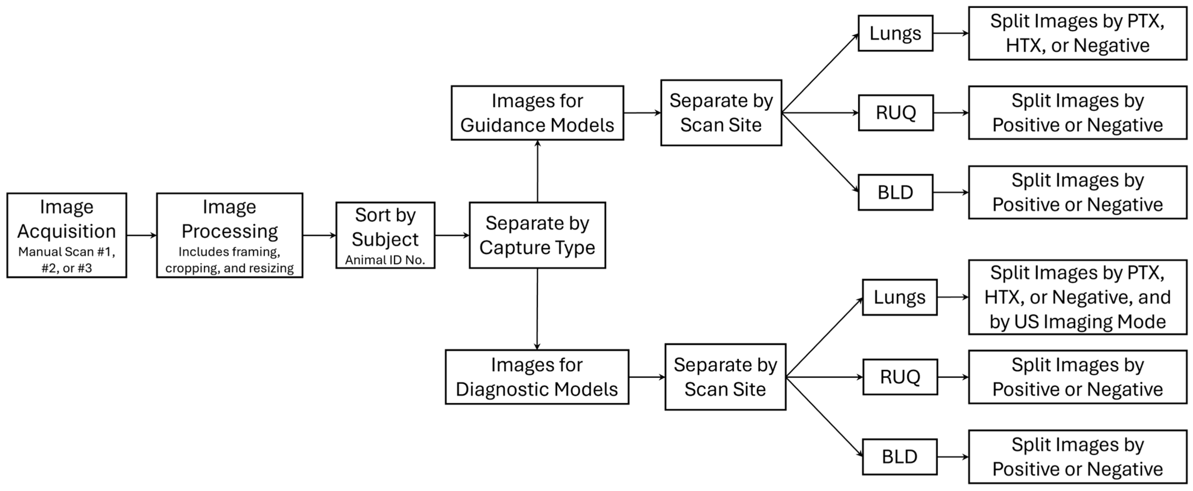
2.2. Data Processing

Ultrasound data from 36 pigs were exported from the US machine and sorted by experimental phase, subject ID, and scan point for both major scan types: guidance (scans along anatomical planes) and diagnostic (scans focused on organs, fluid accumulation sites), as diagrammed in Figure 2. All ultrasound videos were split into frames, and individual images were cropped and resized to 512 × 512 pixels using the Image Processing Toolbox extension from MATLAB version R2023b (MathWorks, Natick, MA, USA). Images were cropped to remove words and other artifacts on the US scans that the AI model may have focused on during training. The US scans were reshaped to a 512 × 512 pixel size to create a symmetrical image geometry at a high resolution to detect small injury features. We have developed successful US AI models for similar applications using this image input size [23]. For guidance frames, datastore file types were created containing random samples of the data, with major anatomical features labeled with bounding boxes around them: ribs for thoracic scans, the kidney for RUQ, and the bladder for BLD. Once the labels were generated, images in which the feature was not obviously visible were removed from the dataset. The bounding box labels were exported from MATLAB as four coordinates: x, y of the top left corner, and x-length, y-length of the bounding box.
For diagnostic scans, images captured during the pre-splenectomy and pre-injury phases were preliminarily classified as negative for injury and the post-injury captures as positive for injury. Then, a file tree of all items was generated, which allowed the review of every entry. As part of data curation prior to training the AI models, all US scans were reviewed for the presence of injury and assessed for overall image quality score, injury severity (none, slight, positive), and the presence of motion artifacts (only applied to thoracic scans). Image quality evaluated whether the US scans could be used to diagnose an injury. A score of 1 corresponded to a poor image quality, with most frames captured at an incorrect location; a score of 5 corresponded to a high image quality captured at a proper eFAST scan point, where diagnostic status could be properly assessed. This was performed by two scorers who agreed on image quality scores for the initial frames to help standardize scoring and conferred to finalize data curation if disagreement occurred for any image. When selecting data for training the AI models, those with a signal quality score below 3 and thoracic scans with large motion artifacts were not included in the training datasets. Scans labeled as “slight” injury were maintained in the dataset as positive for injury. An overview of the AI model types used in this effort is shown in Figure 3.

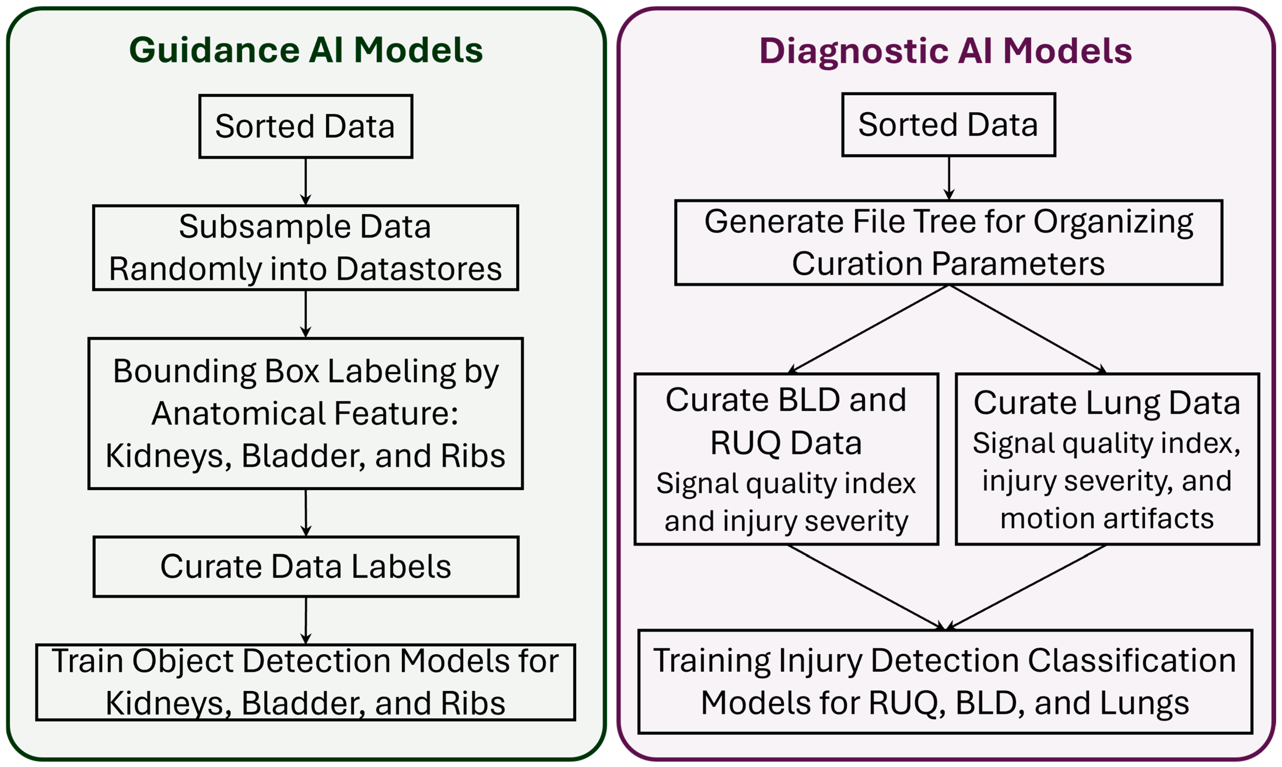
2.3. Guidance AI Models

Once the data were labeled, the guidance AI models were trained using the YOLOv8 [24] object detection architecture, with separate models tailored specifically for the detection of the kidneys (9449 labelled US images), bladder (7039 labelled US images), or ribs (44,736 labelled US images). The training process utilized the YOLOv8-S pre-trained model weights, default training parameters, and 100 epochs to provide ample opportunity for the models to learn and refine their predictions. To ensure robust model validation, a distinct dataset from subjects not used in training was reserved for the holdout testing of model performance. YOLOv8 was selected as the model architecture due to a variety of advantages when compared with other state-of-the-art object detection models. Primarily, this effort focused on the real-time application of object detection models with an eFAST-focused purpose. This meant that speed of prediction time was of high importance, even at the expense of slightly reduced accuracy. This narrowed the scope of possible models to be used to ‘single-stage’ architectures, where the single-stage model undertakes a single pass through of the image through the layers to determine the object location and class. Models like Faster R-CNN, which can be more accurate, have a slower prediction time due to the image being processed into proposed regions of interest before being classified for objects. Moreover, when looking at single-stage models, YOLOv8 was amongst the fastest in frames per second, even beating out the single-shot detector (SSD) model and having only a slightly worse detection accuracy [25,26]. Ease of use was also a driving factor for the use of YOLOv8 in this environment. The Python library ultralytics [27] provides an API to allow for the seamless integration of YOLO models into existing software.
For each guidance model trained, predictions were compared against the ground truth labels for the respective image, and Intersection-Over-Union (IOU) scores were calculated for each image. IOU is a common metric for evaluating object detection models, calculated by dividing the area in which the predicted mask and ground truth mask overlap (intersection) by the total area covered by both masks (union). An IOU threshold of 0.5 is widely accepted in object detection applications as a standard for evaluating model performance, with scores at or above this threshold being acceptable [28]. For kidney and bladder predictions, one object was expected for each frame, whereas for the thoracic image, two objects were expected. Regardless, for all predictions, the IOU score was calculated as an average across the entire image.

2.4. Diagnostic AI Models

For the development of diagnostic AI models, different approaches were used for the thoracic and abdominal regions. Each approach utilized the same YOLOv8 model architecture, except configured for classification for this use case. Diagnosis of injury in the abdominal region is regularly made from B-mode scans; as such, AI models were only trained using this type of imaging. In the thoracic region, due to the nature of lung sliding and how injuries present in ultrasound, M-mode images are a common means of distinguishing between injured and non-injured states. Diagnostic models trained for the thoracic region used two approaches: predictions from US-system-generated M-mode scans, or custom-generated M-mode images from a static hold in B-mode imaging mode. The latter approach is described below, followed by overall AI training procedures for the other scan points.

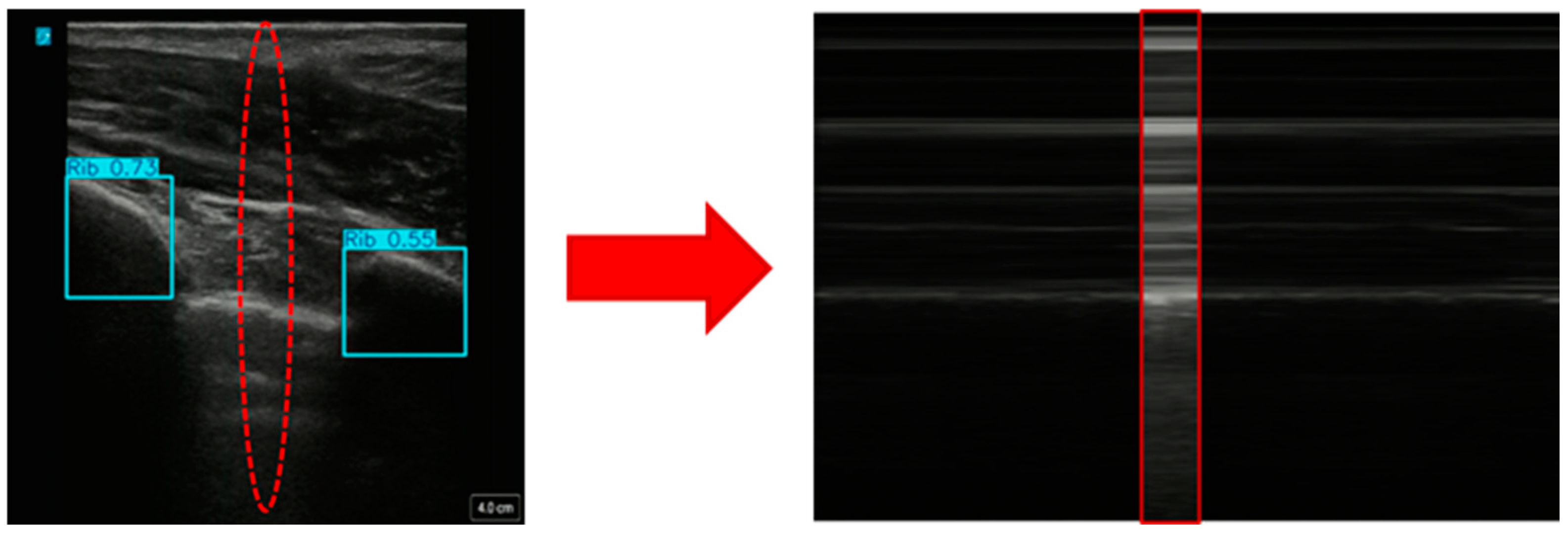
2.4.1. Creating Custom Motion Mode Images from US Scans

For the development of diagnostic models focused on the thoracic region, we first generated M-mode images from the original B-mode US scans. This approach used a sequence of consecutive frames to create custom M-mode images. Each frame was processed through the guidance model for rib detection and, based on the predicted rib locations, the central point between the ribs was calculated. At this central point, a vertical slice was extracted from each frame (Figure 4). These slices were then concatenated to generate an image that closely resembled a genuine M-mode image. To ensure that a generated M-mode image was indicative of its diagnosis, the rib detection guidance model was used to filter out images without only two ribs visible. If a frame did not have exactly two ribs detected, that set of subsequent frames was not used for the M-mode creation process.
An optimization process was conducted to determine the ideal set of parameters used to generate the images. These parameters included the number of frames per image, the width of the slice taken from each frame, the window stride between images, and the number of slices taken from each frame. The first two optimization parameters were concerned with the makeup of the generated M-mode images. For frames per image, we tested 30, 90, and 150 frames per image. Images were captured from a video running at 30 frames per second, so these represent 1, 3, and 5 s capture windows. Three slice widths were also tested, these being 1-, 3-, and 5-pixel widths.
The remaining optimization parameters were focused on the generation of our training image dataset. The window stride parameter refers to the number of frames the model moves forward between images. For example, if using 30 images per generated M-mode and a stride of 15, one generated image will use frames 1–30, and the next will use images 15–45. The stride options used during the optimization were either 6 or 15 images. The final optimization parameter was the number of slices taken from each image, with either 1 or 3 slices being taken from each image. These parameters would affect both the number and makeup of images present in the training dataset.
These options produced 36 unique combinations of training parameters to be validated in the grid search using a YOLOv8 classification model trained for 100 epochs. After optimization, the resulting best parameters were as follows: 150-frame window size, 5-pixel slice width, 15-frame stride, and 1 slice taken per frame.

2.4.2. Training AI Models for Injury Identification

The diagnostic models were trained for injury detection at each eFAST scan site. For the abdomen, the AI models to identify AH injury were trained independently for the RUQ and BLD scan sites. For the thorax, two separate models were trained to predict if there was HTX, PTX, or no injury present, using either US-system-generated M-mode images or the custom generated ones as the input data. The dataset was split into 3 groups of 13 swine each to be able to perform the leave-one-subject-out (LOSO) cross-validation methodology. Each unique LOSO group was randomly generated from three research protocols and designated as a training, validation, or test set. We previously compared several AI model architectures to develop AI models for each eFAST scan site [19]. With the larger image dataset used in this study, these models needed to be retrained, and, for simplicity, they utilized the same YOLOv8 architecture for image classification that was used for the AI guidance model development. We applied the default training parameters over a span of 100 epochs to allow for sufficient learning and refinement. Predictions were then tested on a holdout set of images from subject data not in the training data to test model performance. The best performing model from each scan site was then selected to be used in real-time testing.

2.5. Real-Time Validation of AI Models

Real-time (RT) image capture was performed in three swine subjects completely separate from the dataset used to develop and test the underlying AI models. Each animal underwent imaging at the experimental timepoints shown in Figure 1. Three real-time approaches were used: (i) RT eFAST application, which allowed for selection of a single scan site and capture of images while AI predictions for guidance and diagnostics occurred in RT; (ii) full handheld, manual eFAST examination, driven by AI guidance and diagnostic models; (iii) automated eFAST image capture using a robotic imaging platform equipped with computer vision, guidance, and diagnostic AI models. Each of these approaches is described in more details below.

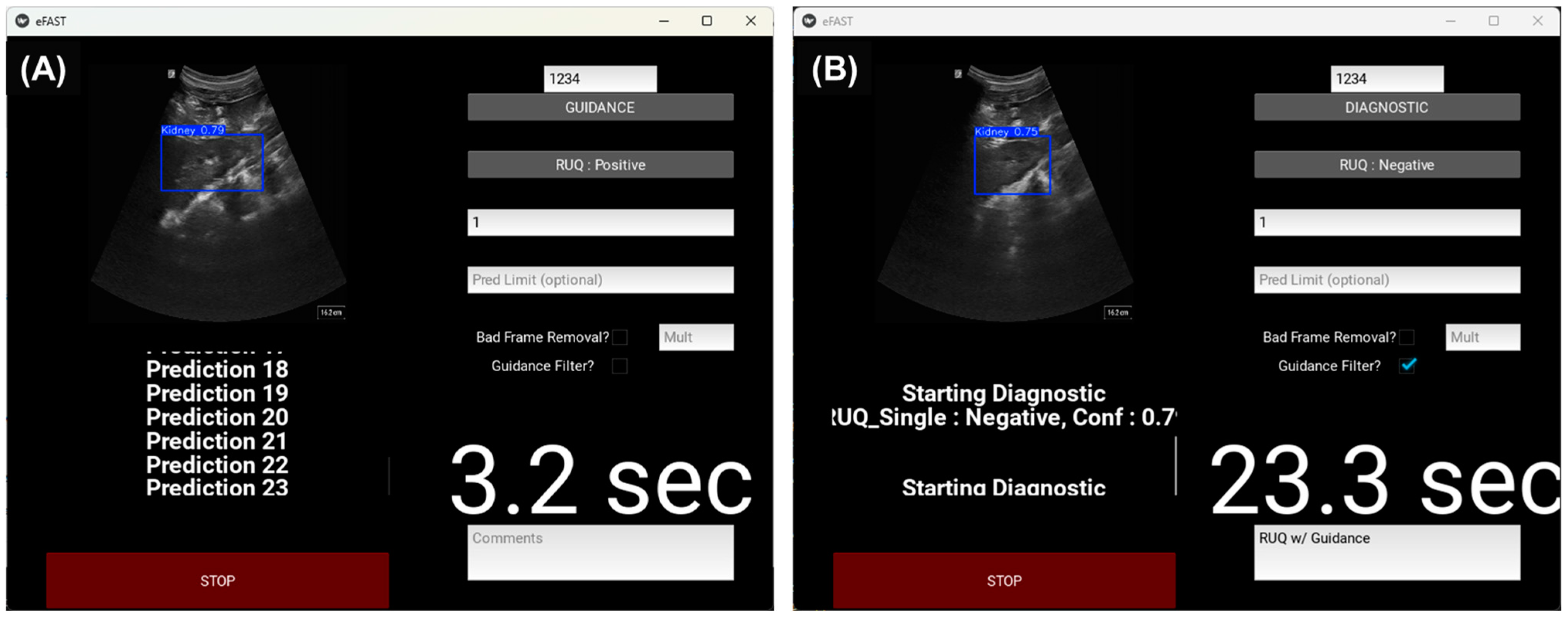
2.5.1. Real-Time eFAST Application

To enable the RT testing of models, a dedicated graphical user interface (GUI) was developed in Python using the Kivy library and designed to run on a laptop connected to the US machine via a Magewell USB Capture HDMI Gen 2 capture card (Magewell Electronics Co., Reading, PA, USA). The RT eFAST application allows users to input various experimental parameters, including subject identifier, scan mode (guidance or diagnostic), scan site (BLD, RUQ, M-mode, or RibsAI to generate M-Mode images), injury status, and number or duration of predictions (Figure 5). Additionally, the interface provides a comment section, with all inputs saved as a text file in addition to the prediction results from each individual scan. The best performing model for each scan site and method that received the best blind test accuracy score was selected to be used in the real-time experiments. The trained model weights were packaged along with the GUI code to allow for the quick deployment of models and switching between models in real time. Users also have the option to select filtering methods that can be applied during the scan, as shown in Figure 5B; these are further described in the next section.
The RT eFAST application can be used for testing AI models in real time, as well as for data collection while performing the eFAST exam. The GUI allows the user to select relevant parameters for the operation and to start image capture. This in turn initializes the video stream and activates a thirty-second timer, which is displayed on the application. US imaging and RT predictions run for thirty seconds or until the specified number of predictions is reached, whichever comes first. While the scanning mode is active, the predictions and corresponding images are shown in real time, along with the prediction confidence scores. To ensure smooth operation, process threading was employed to make predictions concurrently, preventing any interruption to the RT eFAST application’s functionality. The system processed one frame at a time, waiting for each prediction to finish before loading the next frame.
As part of the data collection feature, the program can save all frames captured between predictions. A results folder was generated for every scan, containing subfolders for the saved intermediate frames and one for the frames used for the predictions, a CSV file listing model predictions with confidence scores, and a TXT file with user-input comments. For guidance scans, predicted images were stored with overlaid object detection boxes.

Ultrasound Image Filtering Features

Several filtering options are available to the user while scanning: bad frame removal, guidance filtering, and the option to turn both of these on at the same time. The bad frame removal filtering option performs an analysis of each image to quantify the quality of the image based on intensity-based and texture-based features before predictions are made. To attain this functionality, a sample of 2000 images was taken from each scan site in the dataset and then analyzed using noise and pattern analysis to find some correlation between the ultrasound images labeled “bad” and quantifiable characteristics, such as average pixel intensity, the standard deviation of pixel intensity, entropy, or the signal-to-noise ratio. Images were labeled “bad” by two US operators based on the quality of the image and the ability to make a diagnostic prediction from the image. The metrics that indicated the strongest correlation to image quality were the average and standard deviation of pixel intensity, corresponding to the brightness and contrast of the images, respectively. Using this analysis, the most ideal values for brightness, contrast, and the signal-to-noise ratio were selected as the parametric floor to classify an image as a bad frame. The user also has the option to adjust the aggressiveness of bad frame removal from the GUI by entering a multiplier value to be applied to the bad frame parameters. Bad frame removal was only used for the RUQ and BLD sites, as the M-mode capture process required multiple seconds of undisturbed data capture, making bad frame removal not possible during this capture process.
In addition to bad frame removal, we developed a guidance filter as a second filtering option. For this process, streamed frames were passed through the guidance model for the designated scan site before any predictions were made. The guidance AI models evaluated each image for the identification of relevant anatomical features, such as two ribs, a bladder, or a kidney. If these features were not detected, the GUI bypassed the frame and moved on to the next available one without making a diagnostic AI prediction. For the rib models, guidance occurred at the start of the scan. Once two ribs were identified, the GUI prompted the user to hold still for M-mode capture until the scan was complete, whether it was real or generated. For the RUQ and BLD models, guidance was applied before each prediction, with the model only proceeding if the appropriate anatomical features were detected in the image. When both filters were active, images were passed through bad frame removal first, followed by guidance filtering.

2.5.2. Manual eFAST Exam with AI Model Guidance

A python script was developed to test the guidance and diagnostic AI models during a full eFAST exam, recording the time taken to complete each scan point. The script prompted the operator to follow a scan order of upper-left thorax, lower-left thorax, upper-right thorax, lower-right thorax, RUQ, and BLD. For each scan point, the user prompts, model predictions, and the times taken to complete each scan were displayed in the command terminal. At the lung scan sites, the guidance model for lungs ran until it detected two ribs, and then prompted the user to stay in that location while it made three predictions using generated M-mode images, before telling the user to move to the next scan point. For RUQ and BLD, the user had to swap to the curvilinear transducer and then the guidance model ran continuously, only making a diagnostic prediction when the kidney or bladder was detected, until it reached 30 predictions. This imaging application was run in two modes: one in which the operator viewed the ultrasound screen during the exam, and a second “blind” scan where the user was unable to see the display. The manual eFAST exam with RT AI predictions was performed at the timepoints specified in Figure 1.

2.5.3. Automated Robotic US eFAST Exam

A UR5e robotic platform (Universal Robots, Odense, Denmark) was configured for semi-autonomous eFAST examination (Figure 6). The UR5e was programmed to navigate to eFAST scan sites using computer vision and stereo vision technology. Once at the scan site, the robotic arm was programmed to capture ultrasound images using a custom-made ultrasound probe holder to position the ultrasound probe and using integrated force feedback to apply the probe to the subject. Robotic navigation and image acquisition were further assisted by ultrasound-based guidance feedback that allowed the robot to search a scan site at several positions until relevant anatomical features were in view of the image. Finally, the ultrasound images captured by the UR5e were evaluated for injury interpretation using the diagnostic AI models.

Robotic Platform Configuration

The computer vision AI model was developed to detect the location of relevant scan sites on the subject’s body using external image features. Ultrasound images were used to confirm the location of the relevant anatomical features for each scan site, and a fiducial target in the form of a circular color-coded sticker was placed on the body of the subject at this location. The UR5e was programmed to travel around the body of the subject, capturing images using an Intel RealSense 435i camera (Intel, Santa Clara, CA, USA). Images were captured with and without the targets placed on the subject. eFAST scan sites were then labeled in MATLAB using the images that included targets. This process was repeated so that the image training dataset comprised images captured for two subjects. A computer vision model was then trained using YOLOv8s to accurately identify the color-coded stickers. Images of swine were also captured without stickers present to determine if the AI models could accurately identify scan sites without stickers present. Unfortunately, not enough data were captured for training models for this application and the computer vision models for detecting stickers at each scan site were used. IOU scores were calculated for model predictions during the testing performed on the three swine subjects reported in this study based on agreement between ground truth labeled sites and AI model prediction.
During testing, the UR5e was positioned over the subject at mid-torso using a hoist–lift structure (Figure 6). The UR5e was programmed to capture four images of the top, left side, and right side of the pig using an Intel RealSense camera fixed to the end of the robotic arm. For each image, the computer vision model was used to detect the location of each scan site, providing the UR5e with real-world scan site coordinates for computer-vision enabled navigation. The model returned the pixel value of the center of the color-coded targets that were detected in each image. Next, with the inherent depth reading capabilities of the Intel RealSense camera due to stereo vision technology, the real-world 3-dimensional location of the target relative to the lens of the camera was determined. The 3-dimensional location of the target was then transformed to the robot’s coordinate system, allowing the robot to navigate to the scan site and apply the probe for image acquisition.
The quality of image acquisition was improved by using ultrasound image-based guidance feedback to scan a site, capturing multiple US images until an US image was acquired that could be used for proper diagnostic interpretation. For the abdominal sites, eight additional scan locations positioned in a circle equidistant apart at a 2.54 cm radial offset from the location of the original scan site were available for image capture. For the thoracic sites, the robot was programmed to scan linearly in intervals of 1.2 cm in the caudal direction before scanning another set of sites, following a line slightly offset in the same direction. This resulted in a total of 7 potential scan site positions for evaluation.
In addition to finding all the scan sites, radial positions, and linear positions on the subject, it was necessary to ensure that the probe was oriented orthogonally and applied sufficient contact force to the surface to receive a clear ultrasound image. To do so, depths were measured at the detected scan point, so that the slopes of the measured surface could be used to calculate the correct roll, pitch, and yaw coordinates that would allow the robot arm to position the probe normal to the surface at each scan site. By accounting for the local curvature of the anatomy of the subject, adequate contact was sought between the surface of the ultrasound probe and the surface of the subject at each scan position. For the abdominal scan sites, a rocking B-mode scan was performed, where upon reaching an adequate position, the robot rotated to four different angles at a 5-degree offset relative to the scan site and collected a set of ultrasound frames at each different angle to pass to the diagnostic model. The set of ultrasound frames was acquired over a period of a tenth of a second for both the guidance and diagnostic scans, yielding between 5 and 7 frames.

Robotic eFAST (RoboFAST) Exam with AI Model Guidance

A set of three RoboFAST exams, each with a different set of criteria, were run on each of three experimental swine subjects at the two post-euthanasia timepoints (Figure 1). All trained diagnostic and guidance AI models were integrated into the RoboFAST algorithm to assess the robotic platform’s capabilities and compare its performance to the manual eFAST exam performance. Upon detecting all scan sites and converting the pixel coordinates to coordinates relative to the origin of the robot, the robot started the respective experimental run.
The first run, referred to as “Radar”, conducted a general eFAST exam where the robot scanned both the original scan site and additional radial and linear positions until the guidance AI model returned that the proper organ or anatomy was present, indicating that a suitable location to run the diagnostic model was found. If no such detections occurred, the robot moved on to the next site without conducting a diagnostic prediction. However, when the guidance AI returned that the relevant object was detected, the diagnostic AI provided an injury prediction result for five consecutive frames. For the second run, referred to as “No Radar”, the robot performed a single image capture at the location where the colored sticker was detected. For the third experimental run, referred to as “All Radar”, the robot performed image capture at each scan site and all of the corresponding additional positions, running the diagnostic AI multiple times depending on how many positions at a site contained suitable locations. The plurality of what the diagnostic model returned then determined the prediction of the RoboFAST algorithm.

3. Results

3.1. Guidance AI Performance

For each guidance model trained, model performance was evaluated against a test dataset comprising images from subjects not included in the training data. Examples of high and low IOU scores are shown for each guidance model in Figure 7A. The resulting average IOU scores varied across each model, with kidneys having the highest score at 0.94, followed by the ribs and bladder at 0.74 and 0.58, respectively (Figure 7B). The precision and recall metrics were also strong for each guidance model, apart from precision for the bladder model, which was only 0.65 (Figure 7B). A higher false-positive rate due to the pixels being identified as bladder in the model’s prediction but not in the ground truth image resulted in this lower score for the bladder model. Overall, each model was trained at variable performance levels and was able to correctly identify anatomical features to aid with proper eFAST US image acquisition.

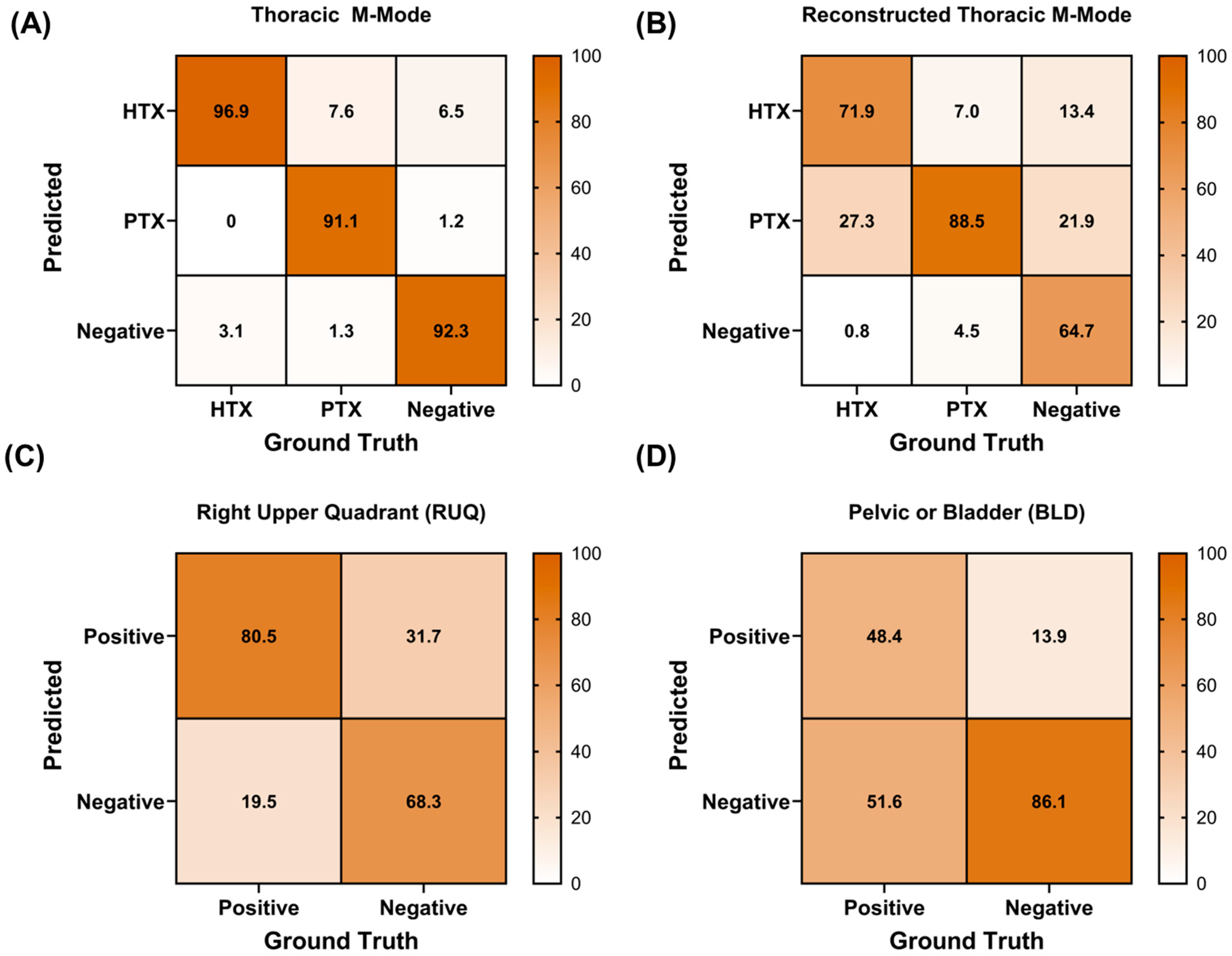
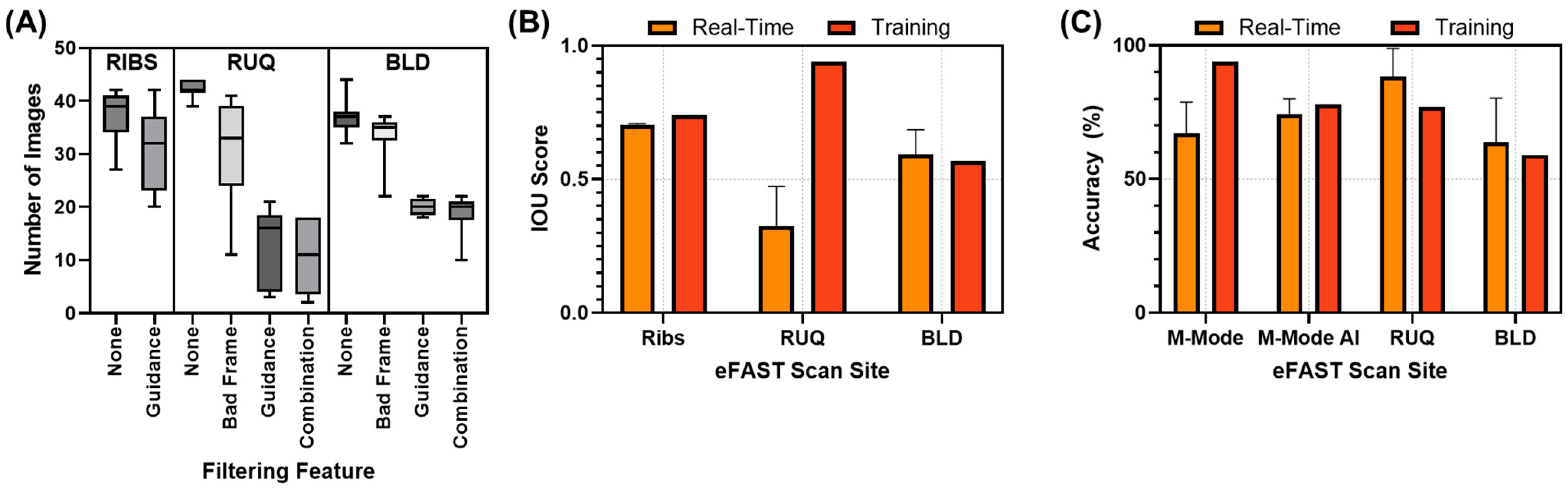
3.2. Diagnostic AI Performance

For thoracic diagnostic models, models were trained for both M-mode and generated M-mode diagnostic models (as described in Section 2.4.1). The M-mode diagnostic model predictions had a higher accuracy compared to the generated M-mode diagnostic models, at 0.94 vs. 0.78 accuracy, respectively. From the confusion matrix analysis, the generative M-mode models had a higher accuracy for the ground truth PTX predictions but identified 27% of the ground truth HTX images and 22% of the negative images as PTX (Figure 8A,B). Conversely, M-mode models had a slight bias toward HTX predictions, with 7.6% and 6.5% of the PTX and negative ground truth images being incorrectly identified as HTX-positive. We further developed RUQ and BLD diagnostic prediction models, which were binary in nature: positive or negative for abdominal hemorrhage. The RUQ models reached 0.77 accuracy but had a lower specificity metric of 0.68 compared to a higher recall of 0.80, hinting at slight bias toward positive predictions across the testing dataset (Figure 8C). As for the BLD models, overall performance remained lower at 0.59 accuracy, with a much larger bias toward negative predictions in the testing dataset, as indicated by the confusion matrix and 0.49 recall metric (Figure 8D).

3.3. Real-Time Model Performance

We conducted real-time testing in three different ways. The first used the RT eFAST application and was primarily used to evaluate the AI guidance and diagnostic model performance at each scan site, along with the utility of different filtering approaches. The other two approaches were the manual, handheld eFAST exam with AI model feedback and RoboFAST. Both of these approaches allowed for a full eFAST exam to measure the timing of the procedures and how the AI models synergized with various image acquisition approaches.

3.3.1. Evaluation of the Real-Time eFAST Application

Starting with the RT eFAST application, the different filtering methods impacted the number of images that were captured at each scan site during a 30 s data capture window (Figure 9A). For ribs, on average, six less images were captured when using the guidance filter (approximately 37 vs. 31 images). Bad frame filtering was not applicable at this scan point due to M-mode capture needing to be continuous and not interrupted by frame removal procedures. The effects were more noticeable with RUQ and BLD, where bad frame filtering reduced the number of images by 12 and 3 images, respectively, while guidance filtering reduced the number of images by 30 and 16 images, respectively. Compounding these approaches reduced the number of images sent to the diagnostic models by 32 and approximately 18 images, respectively.
Next, we evaluated how the guidance models performed using the RT eFAST application. This was undertaken without any filtering methods applied to obtain an overall IOU performance metric for each scan site (Figure 9B). In real time, performance decreased for ribs (0.70 real time vs. 0.74 training) and more substantially for the RUQ (0.33 real-time vs. 0.94 training), while BLD performance slightly increased (0.59 real time vs. 0.57 training). In terms of diagnostics, the effects of these filters on overall diagnostic accuracy were minimal, so the averaged diagnostic accuracy results comparing training performance are shown in Figure 9C. Performance was comparable to training data, with the exception of the M-mode thoracic model, which had a reduced accuracy of 0.67 compared to 0.94 during model training.

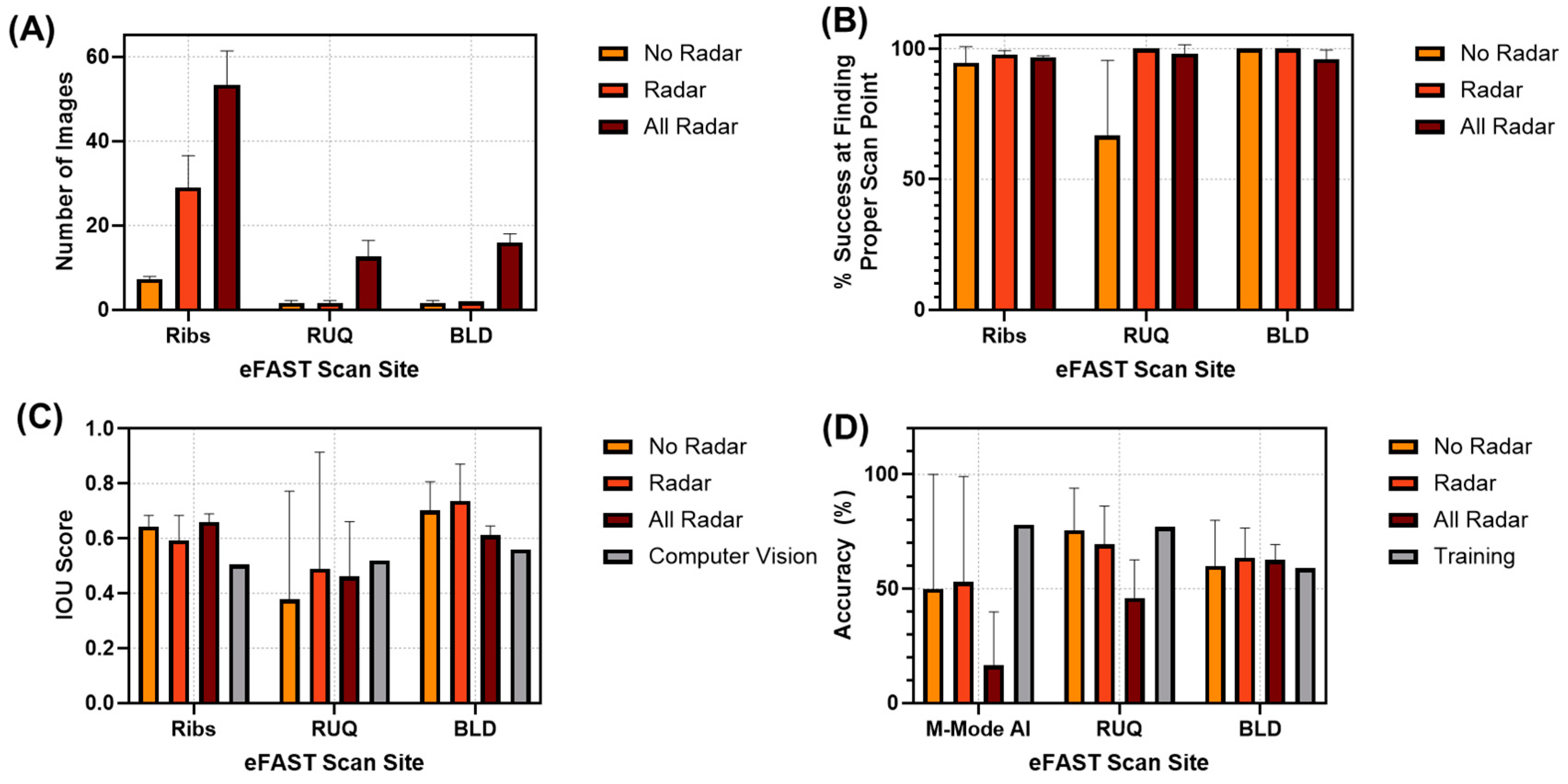
3.3.2. RoboFAST Evaluation

The robotic imaging platform relied on a computer vision model to identify each eFAST scan site automatically. The IOU scores for these predictions across scan sites were as follows: 0.51, 0.52, and 0.56 for ribs, RUQ, and BLD, respectively (Figure 10C). For US image capture, three approaches were used to capture images, as described in the Section 2, using the Robotic eFAST (RoboFAST) exam with AI model guidance: Radar, No Radar, and All Radar modalities. We first evaluated the effects of the various methods on the total number of images captured (Figure 10A). As anticipated, the All Radar approach captured the most images for each scan site, while No Radar and Radar had similar numbers of images for the RUQ and BLD scan sites. We next quantified the overall success of each scan site across the three swine subjects, where success is defined as at least one image being captured that could be used for diagnosis (Figure 10B). All approaches had high performance here, except for the RUQ/No Radar approach at 67% success. Factoring this in, Radar and All Radar had similar performance levels for this evaluation criterion. The guidance model IOU performance scores were similar for each RoboFAST imaging modality, with BLD having the highest IOU scores and RUQ performing the worst and having the highest subject variability (Figure 10C).
Lastly, we evaluated the diagnostic model performance. The All Radar modality resulted in the lowest accuracy for the M-mode thoracic AI (16.5%) and RUQ (46%) models (Figure 10D). Radar and No Radar performed similarly at each scan site. Compared to the test results obtained during model training, BLD and RUQ were comparable to the RoboFAST captured accuracies, while RoboFAST severely underperformed for the thoracic scan sites. This was likely a result of the robotic imaging platform experiencing difficulty reaching the proper thoracic scan site where pleural space was present, as shown in the representative US images captured during RoboFAST (Figure 11).

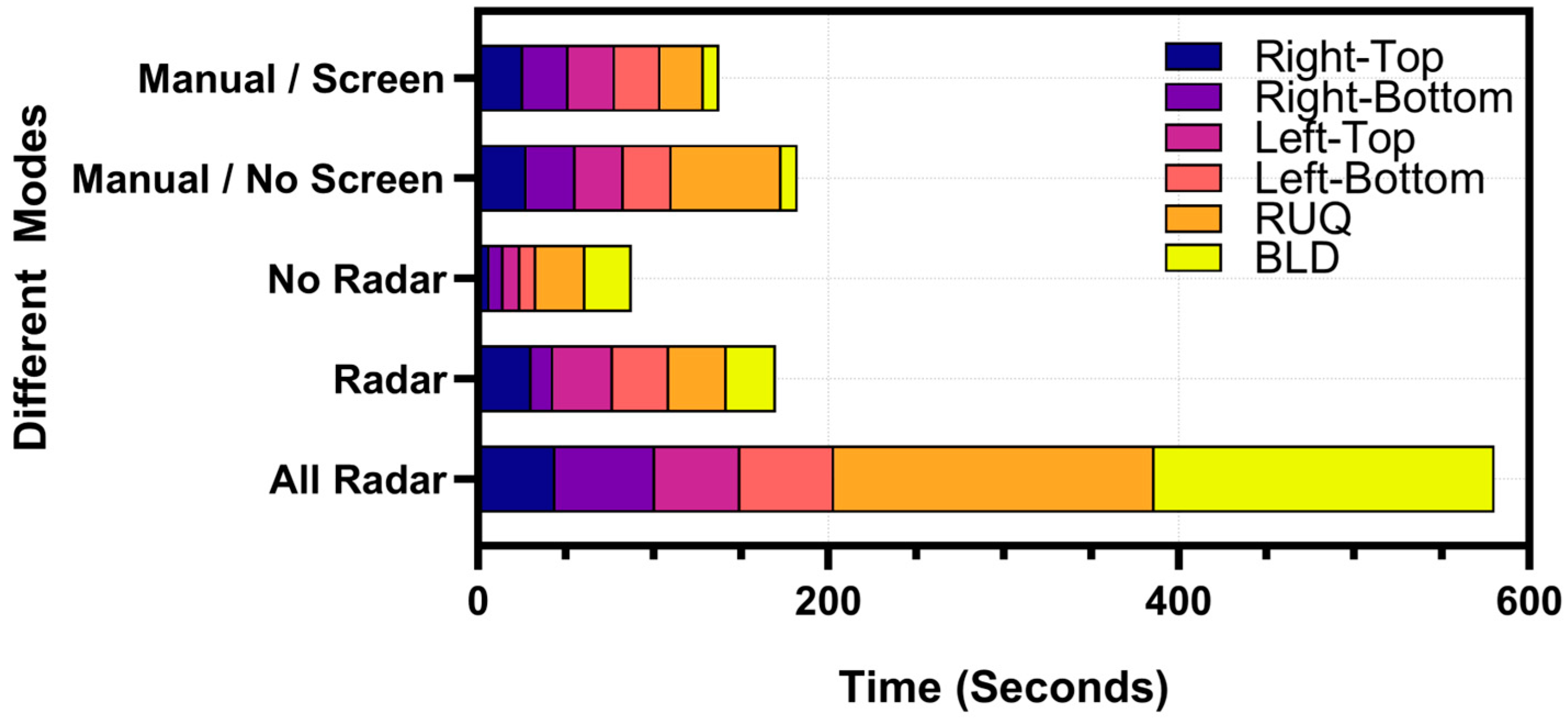
3.3.3. Timing Comparison Between Handheld eFAST Application and RoboFAST

Ultimately, we compared the overall time required to complete two RT eFAST imaging methodologies (Figure 12). Instead of the RT eFAST application, we configured the AI models for use in sequence across six total scan locations to mirror how the images were captured with the robotic imaging platform: (i) right thoracic top and (ii) bottom, (iii) left thoracic top and (iv) bottom, (v) RUQ, and (vi) BLD (described in Section 2.5.2). This matches the number of scan sites used during RoboFAST. We evaluated the timing of image capture by the end user having or not having the US screen visible (only relying on AI predictions and instructions to move to the next scan site), which resulted in a slightly longer time on average with no screen visible compared to when the screen was present (138 s manual, screen vs. 183 s manual, no screen). The RUQ scan site was most impacted by not looking at the US screen, as most captured images were excluded by the guidance filter. For the robotic imaging platform, the No Radar modality was the quickest (87 s), with rapid thoracic image capture compared to the slower Radar image capture (170 s), and the overall slowest All Radar modality (580 s).

4. Discussion

As ultrasound technology becomes smaller and more portable, its potential utility in emergency medicine widens. Pre-hospital triage by US imaging may be possible if the challenges of imaging can be reduced so that less-skilled personnel can perform initial triage assessments. This is especially true for military medicine, where triage decisions in the battlefield must prioritize limited evacuation opportunities in scenarios where air evacuation is not readily available, as has been the case in the ongoing conflict in Ukraine [29]. The AI-driven tools showcased in this research demonstrate how US imaging can be simplified to lower the skill threshold for triage on future battlefields or in other civilian emergency situations.
We have previously developed AI models for the diagnostic evaluation of eFAST scan sites, so this research effort was predominately focused on the automation of image acquisition techniques. Guidance object detection AI models were built using a YOLO model architecture, which was further tuned for use with swine datasets. Performance was mixed in the real-time implementation of these models, with BLD and RUQ underperforming compared to rib detection models. However, this still highlights how guidance models could assist with real-time scanning. These models can be used as a filter during manual scanning to exclude all frames in which key anatomical features are not present. Additionally, they may be used to provide autonomous feedback to robotic image acquisition platforms to acquire images with evident anatomical features that are required for proper diagnostic interpretation. However, these models need further refinement to ensure that not only anatomical features are present in the image, but also that the ideal anatomical features for diagnostic determination are identified. For instance, our models confirmed the presence of two ribs in each image so that the pleural space between the ribs can be evaluated for diagnosis. However, if the probe is not oriented correctly, the pleural space cannot be seen, making injury identification impossible. Additionally, our model confirms the presence of a kidney in each image to evaluate RUQ scan sites. However, since fluid often pools around the edges of the kidney, guidance models could be improved by confirming that the edges of the kidney are in view so that images used for diagnostic interpretation capture the area most likely to demonstrate evidence of injury. These additional improvements would further enhance their utility in providing ultrasound-based guidance feedback for image acquisition during an eFAST examination.
In addition, diagnostic AI models were further refined prior to further developing the models for real-time application. US image sets were expanded to more than 35 swine subjects to ideally allow for more robust model training performance. For simplicity in this study, all models were developed using a YOLOv8 image classification model. However, the guidance models were consistently more accurate compared to the new diagnostic models. A likely reason for the difference in model performance is that the guidance models were required to identify anatomical landmarks, while the diagnostic models were tasked with the more difficult task of interpreting nuanced changes in variable injury sizes. In the real-time testing, the BLD diagnostic models performed at low accuracy levels of 50–60%, similar to the initial model training performance. The overall low BLD performance could be due to three primary challenges: one, the additional image variability due to the size of the bladder being more variable than anatomical features at other scan sites; two, on US scans, the bladder presents as a dark fluid-filled feature, similar to abdominal hemorrhage fluid, possibly making the AI training task more complex; three, the urinary catheter balloon is often in view in the US scan images, which could be adding an additional artifact to the BLD training process. Additional image curation, robust model architecture, and rigorous model fine-tuning will be needed to improve AI training performance and the use of these models for real-time image interpretation. As for the methods of exploring model architectures, deep learning models used for segmentation can be applied to localize features of injury to help the models attribute the presence of fluid around the bladder, resulting in positive classifications. Long short-term memory (LSTM) networks used in video analysis can be explored to give the models more context on the appearance of variable injury sizes when making predictions on sequential images. Lastly, adding filters or pre-processing techniques with the purpose of amplifying relevant areas of the bladder can be tested for model training to help differentiate features between classifications.
AI models were evaluated in real time, with and without a robotic imaging platform, highlighting the different end-user applications of this technology. The handheld manual AI-guided application had faster performance, but still requires a user to position the probe in the right location. Filtering approaches were used to exclude images that were not suitable for diagnostic evaluation, which resulted in the exclusion of a large number of images from the diagnostic pipeline. Image filtering is critically needed for automated image acquisition in a handheld format, as less-experienced users may place the ultrasound probe at incorrect positions that may not have been included in diagnostic AI training datasets, resulting in a higher likelihood of incorrect diagnostic predictions. Rather than try and make diagnostic models more robust to handle these irregular images, filtering applications can prevent these images from impacting diagnostic predictions. Unfortunately, due to the lower performance of some of the diagnostic models during testing, it is hard to evaluate the effects of some of these filtering methods on overall eFAST performance metrics. Larger datasets paired with modified diagnostic models are needed to finalize the development of these filters and manual AI-guided eFAST image capture techniques.
However, there are some limitations with these filtering approaches when used in real time. For instance, over-filtering can result in removing viable images for diagnostic evaluation, leading to reduced model performance. Both bad frame removal and guidance filtering approaches could contribute to the over-filtering issue. The parameters for the bad frame removal filter were generated from a subset of 2000 images per scan site; as a result, the image subset could be not representative of the entire dataset or real-time testing data, leading to performance issues. Similarly, the guidance filter could impede real-time performance based on the guidance models’ own performance biases. Further, the identification of anatomical features is not always indicative of where fluid pools around organs or in the pleural space. Another challenge with real-time implementation is the loss of image resolution and introduction of artifacts due to streaming the US signal. To account for this effect, the inclusion of streamed frames at different resolutions in AI model training data should be considered for improving performance in future implementations of this technology.
For the robot image capture platform, different configurations had a wide impact on the speed of performing an eFAST examination. However, this is mostly tied to the number of images that were being captured and the carefulness being applied to ensure that a proper eFAST viewpoint was captured at each scan site. The robot’s limited range of motion was challenged by the deeper angles required to image the RUQ or the lower thorax, where HTX injuries are often identified. This was due to the bulkiness of the platform and poor clearance with the table on which the subject was placed. Guidance models performed as expected; however, diagnostic accuracies for the thoracic scan sites were low. This was not exclusively due to issues with the model, but also challenges with the robot’s ability to correctly position and angle the probe on the chest to properly image two ribs in the area that was searched. More gradual movement and better tracking of the proper direction to move across the thoracic cavity could improve performance in future iterations of RoboFAST. Conversely, the RUQ and BLD had similar accuracy to the testing results of the diagnostic models. This provides evidence of the utility of robotic mechanisms to automate image capture, but more work is needed to further ready this platform for rapid and proper eFAST image acquisition.
The utility of the handheld and robotic eFAST imaging platforms differ greatly in their potential applications. Obviously, a large robotic system is not feasible in all pre-hospital settings but could be envisioned at a site for processing mass casualty scenarios, for automated triage assessment in a hospital, or later military echelons of care. Less human support is needed once the technology is further refined, so a more automated design can potentially streamline casualty in-processing. In direct contrast, the handheld tool, if paired with small, portable US devices, could be deployed in ambulatory civilian care or military care near the point of injury. While the technology will still require the user to manipulate the technology to proper positions, additional guidance measures in the software application can further lower the skill threshold during real-time deployment.
The next steps for this research effort will expand this application in several directions. First, the underlying AI models for detecting injuries need to reach higher performance metrics to be ready for deployment. This will require a more varied imaging dataset, as well as improvements to the underlying AI. Model performance may be improved if the AI is trained with temporal context from several frames, rather than relying on predictions from a single frame. Further translation of this work will require transfer learning AI models to use with human anatomy and injury states. To accomplish this, a large, curated dataset would need to be acquired through collaboration with emergency medicine departments, where these US images are routinely captured. Second, the real-time handheld application needs an improved end-user interface so that the end user can make smaller adjustments during thoracic scanning to ensure proper M-mode images are captured with varied angles at each scan site. One solution to this challenge is to further refine guidance functionality beyond the simple identification of anatomical features toward a determination of optimal scan placement. For example, if the kidney is imaged with optimal ultrasound probe placement and orientation, the edges of the kidney where fluid is more commonly seen would be in view. In addition, ensuring the pleural space is visible in the thoracic site for proper diagnostic interpretation is necessary. Lastly, the robotic platform will be further automated to overcome some of its limitations. Improved computer vision algorithms for anatomical landmark detection, automated ultrasound gel deployment, and automated probe swapping between linear and curvilinear probe types are just some of the modifications planned to improve this real-time application.

5. Conclusions

Ultrasound imaging can revolutionize medical triage in trauma cases, if it can be pushed further forward to the point where the first medical decisions are made in both civilian and military medicine. Towards this mindset, the real-time AI-driven triage tools showcased here have the potential to lower the skill threshold of image-based triage decisions. The handheld application has a small footprint optimal for ease of deployment if the end user can position the ultrasound probe correctly and make proper image interpretation decisions. The robotic-driven image capture application further automates the procedure; however, it does so at the expense of its larger size, which will not be suitable in the earliest phase of trauma medical care. In conclusion, both applications provide evidence of the promise AI can provide to simplify medical imaging and improve medical triage decisions on the future battlefield and in pre-hospital settings.

6. Patents

Eric J. Snider and Sofia I. Hernandez Torres are co-inventors on a provisional patent filed on the eFAST AI concept and usage (63/686,836; August 2024). Eric J. Snider, Sofia I. Hernandez Torres, and Krysta-Lynn Amezcua are co-inventors on a provisional patent filed on the robotic eFAST imaging concept (63/686,839; August 2024).

Author Contributions

Conceptualization, S.I.H.T., K.-L.A. and E.J.S.; Data curation, S.I.H.T., C.R.T. and E.J.S.; Formal analysis, L.H., K.-L.A. and E.J.S.; Funding acquisition, E.J.S.; Investigation, E.J.S.; Methodology, S.I.H.T., L.H. and E.J.S.; Project administration, E.J.S.; Resources, E.J.S.; Software, L.H., T.W., R.O., K.-L.A. and A.R.; Supervision, E.J.S.; Validation, S.I.H.T., K.-L.A. and E.J.S.; Visualization, S.I.H.T. and E.J.S.; Writing—original draft, S.I.H.T., L.H., T.W., R.O., K.-L.A., A.R. and E.J.S.; Writing—review and editing, S.I.H.T., L.H., T.W., R.O., K.-L.A., A.R., C.R.T. and E.J.S. All authors have read and agreed to the published version of the manuscript.

Funding

This work was funded by the U.S. Army Medical Research and Development Command (IS220007). This project was supported in part by an appointment to the Science Education Programs at National Institutes of Health (NIH), administered by ORAU through the U.S. Department of Energy Oak Ridge Institute for Science and Education (A.R., T.W., R.O., C.T.).

Institutional Review Board Statement

Research was conducted in compliance with the Animal Welfare Act, the implementing Animal Welfare regulations, and the principles of the Guide for the Care and Use of Laboratory Animals. The Institutional Animal Care and Use Committee approved all research conducted in this study. The facility where this research was conducted is fully accredited by AAALAC International.

Informed Consent Statement

Not applicable.

Data Availability Statement

The datasets presented in this article are not readily available because they have been collected and maintained in a government-controlled database that is located at the U.S. Army Institute of Surgical Research. As such, data can be made available through the development of a business agreement with the corresponding author. Requests for the datasets should be directed to Dr. Eric J. Snider, eric.j.snider3.civ@health.mil.

Acknowledgments

The authors acknowledge Evan Ross, Jose Gonzalez, David Owen, Carlos Bedolla, and Benjamin Alexander for their assistance in eFAST image capture throughout the evaluation of the real-time image capture procedures.

Conflicts of Interest

Eric J. Snider and Sofia I. Hernandez Torres are co-inventors on a provisional patent filed on the eFAST AI concept and usage (63/686,836; August 2024). Eric J. Snider, Sofia I. Hernandez Torres, and Krysta-Lynn Amezcua are co-inventors on a provisional patent filed on the robotic eFAST imaging concept (63/686,839; August 2024). No other authors report any conflicts of interest.

DOD Disclaimer

The views expressed in this article are those of the authors and do not reflect the official policy or position of the U.S. Army Medical Department, Department of the Army, DoD, or the U.S. Government.

References

  1. Nabrawi, E.; Alanazi, A.T. Imaging in Healthcare: A Glance at the Present and a Glimpse Into the Future. Cureus 2023, 15, e36111. [Google Scholar] [CrossRef]
  2. Rigal, S.; Pons, F. Triage of Mass Casualties in War Conditions: Realities and Lessons Learned. Int. Orthop. 2013, 37, 1433–1438. [Google Scholar] [CrossRef] [PubMed]
  3. Dubecq, C.; Dubourg, O.; Morand, G.; Montagnon, R.; Travers, S.; Mahe, P. Point-of-Care Ultrasound for Treatment and Triage in Austere Military Environments. J. Trauma. Acute Care Surg. 2021, 91, S124–S129. [Google Scholar] [CrossRef] [PubMed]
  4. Stamilio, D.M.; McReynolds, T.; Endrizzi, J.; Lyons, R.C. Diagnosis and Treatment of a Ruptured Ectopic Pregnancy in a Combat Support Hospital during Operation Iraqi Freedom: Case Report and Critique of a Field-Ready Sonographic Device. Mil. Med. 2004, 169, 681–683. [Google Scholar] [CrossRef]
  5. Remondelli, M.H.; Remick, K.N.; Shackelford, S.A.; Gurney, J.M.; Pamplin, J.C.; Polk, T.M.; Potter, B.K.; Holt, D.B. Casualty Care Implications of Large-Scale Combat Operations. J. Trauma. Acute Care Surg. 2023, 95, S180–S184. [Google Scholar] [CrossRef] [PubMed]
  6. Bloom, B.A.; Gibbons, R.C. Focused Assessment with Sonography for Trauma. In StatPearls; StatPearls Publishing: Treasure Island, FL, USA, 2021. [Google Scholar]
  7. Letter from the President: A Shortage of Preventive Medicine Physicians in the Military and Across the Country. Available online: https://www.acpm.org/news/2024/letter-from-the-president-a-shortage-of-preventive (accessed on 29 November 2024).
  8. Pinto-Coelho, L. How Artificial Intelligence Is Shaping Medical Imaging Technology: A Survey of Innovations and Applications. Bioengineering 2023, 10, 1435. [Google Scholar] [CrossRef] [PubMed]
  9. Liu, X.; Faes, L.; Kale, A.U.; Wagner, S.K.; Fu, D.J.; Bruynseels, A.; Mahendiran, T.; Moraes, G.; Shamdas, M.; Kern, C.; et al. A Comparison of Deep Learning Performance against Health-Care Professionals in Detecting Diseases from Medical Imaging: A Systematic Review and Meta-Analysis. Lancet Digit. Health 2019, 1, e271–e297. [Google Scholar] [CrossRef] [PubMed]
  10. Lotter, W.; Diab, A.R.; Haslam, B.; Kim, J.G.; Grisot, G.; Wu, E.; Wu, K.; Onieva, J.O.; Boyer, Y.; Boxerman, J.L.; et al. Robust Breast Cancer Detection in Mammography and Digital Breast Tomosynthesis Using an Annotation-Efficient Deep Learning Approach. Nat. Med. 2021, 27, 244–249. [Google Scholar] [CrossRef]
  11. Garcia, P. Telemedicine for the Battlefield: Present and Future Technologies. In Surgical Robotics: Systems Applications and Visions; Rosen, J., Hannaford, B., Satava, R.M., Eds.; Springer: Boston, MA, USA, 2011; pp. 33–68. ISBN 978-1-4419-1126-1. [Google Scholar]
  12. Rinehart, J.; Lilot, M.; Lee, C.; Joosten, A.; Huynh, T.; Canales, C.; Imagawa, D.; Demirjian, A.; Cannesson, M. Closed-Loop Assisted versus Manual Goal-Directed Fluid Therapy during High-Risk Abdominal Surgery: A Case-Control Study with Propensity Matching. Crit. Care 2015, 19, 94. [Google Scholar] [CrossRef] [PubMed]
  13. Kramer, G.C.; Kinsky, M.P.; Prough, D.S.; Salinas, J.; Sondeen, J.L.; Hazel-Scerbo, M.L.; Mitchell, C.E. Closed-Loop Control of Fluid Therapy for Treatment of Hypovolemia. J. Trauma 2008, 64, S333–S341. [Google Scholar] [CrossRef] [PubMed]
  14. Vega, S.J.; Berard, D.; Avital, G.; Ross, E.; Snider, E.J. Adaptive Closed-Loop Resuscitation Controllers for Hemorrhagic Shock Resuscitation. Transfusion 2023, 63, S230–S240. [Google Scholar] [CrossRef]
  15. Mohan, A.; Wara, U.U.; Arshad Shaikh, M.T.; Rahman, R.M.; Zaidi, Z.A. Telesurgery and Robotics: An Improved and Efficient Era. Cureus 2021, 13, e14124. [Google Scholar] [CrossRef] [PubMed]
  16. Levy, B.E.; Castle, J.T.; Virodov, A.; Wilt, W.S.; Bumgardner, C.; Brim, T.; McAtee, E.; Schellenberg, M.; Inaba, K.; Warriner, Z.D. Artificial Intelligence Evaluation of Focused Assessment with Sonography in Trauma. J. Trauma Acute Care Surg. 2023, 95, 706–712. [Google Scholar] [CrossRef] [PubMed]
  17. Huang, L.; Lin, Y.; Cao, P.; Zou, X.; Qin, Q.; Lin, Z.; Liang, F.; Li, Z. Automated Detection and Segmentation of Pleural Effusion on Ultrasound Images Using an Attention U-Net. J. Appl. Clin. Med. Phys. 2024, 25, e14231. [Google Scholar] [CrossRef] [PubMed]
  18. Gao, X.; Lv, Q.; Hou, S. Progress in the Application of Portable Ultrasound Combined with Artificial Intelligence in Pre-Hospital Emergency and Disaster Sites. Diagnostics 2023, 13, 3388. [Google Scholar] [CrossRef] [PubMed]
  19. Hernandez Torres, S.I.; Ruiz, A.; Holland, L.; Ortiz, R.; Snider, E.J. Evaluation of Deep Learning Model Architectures for Point-of-Care Ultrasound Diagnostics. Bioengineering 2024, 11, 392. [Google Scholar] [CrossRef] [PubMed]
  20. Amezcua, K.-L.; Collier, J.; Lopez, M.; Hernandez Torres, S.I.; Ruiz, A.; Gathright, R.; Snider, E.J. Design and Testing of Ultrasound Probe Adapters for a Robotic Imaging Platform. Sci. Rep. 2024, 14, 5102. [Google Scholar] [CrossRef] [PubMed]
  21. Boysen, S.R.; Caulkett, N.A.; Brookfield, C.E.; Warren, A.; Pang, J.M. Splenectomy Versus Sham Splenectomy in a Swine Model of Controlled Hemorrhagic Shock. Shock 2016, 46, 439. [Google Scholar] [CrossRef] [PubMed]
  22. Watts, S.; Nordmann, G.; Brohi, K.; Midwinter, M.; Woolley, T.; Gwyther, R.; Wilson, C.; Poon, H.; Kirkman, E. Evaluation of Prehospital Blood Products to Attenuate Acute Coagulopathy of Trauma in a Model of Severe Injury and Shock in Anesthetized Pigs. Shock 2015, 44, 138. [Google Scholar] [CrossRef]
  23. Snider, E.J.; Hernandez-Torres, S.I.; Boice, E.N. An Image Classification Deep-Learning Algorithm for Shrapnel Detection from Ultrasound Images. Sci. Rep. 2022, 12, 8427. [Google Scholar] [CrossRef] [PubMed]
  24. Yaseen, M. What Is YOLOv8: An In-Depth Exploration of the Internal Features of the Next-Generation Object Detector 2024. arXiv 2024, arXiv:2408.15857. [Google Scholar]
  25. Bilous, N.; Malko, V.; Frohme, M.; Nechyporenko, A. Comparison of CNN-Based Architectures for Detection of Different Object Classes. AI 2024, 5, 2300–2320. [Google Scholar] [CrossRef]
  26. Le, V.-H.; Pham, T.-L. Ovarian Tumors Detection and Classification on Ultrasound Images Using One-Stage Convolutional Neural Networks. J. Robot. Control. (JRC) 2024, 5, 21. [Google Scholar]
  27. Jocher, G.; Chaurasia, A.; Qiu, J. YOLO by Ultralytics. 2023. Available online: https://github.com/ultralytics/ultralytics (accessed on 8 January 2025).
  28. Cai, Z.; Vasconcelos, N. Cascade R-Cnn: Delving into High Quality Object Detection. In Proceedings of the IEEE Conference on Computer Vision and Pattern Recognition; IEEE: New York City, NY, USA, 2018; pp. 6154–6162. [Google Scholar]
  29. Epstein, A.; Lim, R.; Johannigman, J.; Fox, C.J.; Inaba, K.; Vercruysse, G.A.; Thomas, R.W.; Martin, M.J.; Konstantyn, G.; Schwaitzberg, S.D.; et al. Putting Medical Boots on the Ground: Lessons from the War in Ukraine and Applications for Future Conflict with Near-Peer Adversaries. J. Am. Coll. Surg. 2023, 237, 364–373. [Google Scholar] [CrossRef] [PubMed]
Figure 1. Overview of animal study procedures and image capture timepoints. Ultrasound images were captured prior to splenectomy in live swine, as well as at two time points in euthanized swine (before and after eFAST injury induction). Each scan landmark in the diagram lists how US images were captured. The three approaches were manual US image capture, image capture using the RT eFAST handheld application, and image capture using the robotic imaging platform.
Technologies 13 00029 g001
Figure 2. Overview of ultrasound image dataset structure and processing for images captured in swine for eFAST AI model training.
Technologies 13 00029 g002
Figure 3. Summary of data flow for eFAST AI model training. For guidance models (diagram on the left), data were subsampled, labeled, and then curated. For diagnostic models (right diagram), the sorted data were curated and then used for classification model training.
Technologies 13 00029 g003
Figure 4. Overview of how M-mode images were generated from B-mode frames using rib guidance AI models. Shown first is a traditional B-mode ultrasound frame from which the guidance AI determined the location of the ribs (blue bounding boxes). A 3-pixel-wide region at the midpoint between the bound boxes (red dotted region) is selected across each frame to create a custom M-mode image (shown on the right).
Technologies 13 00029 g004
Figure 5. Overview of the real-time eFAST application. Developed graphical user interface for (A) guidance AI model use and (B) diagnostic AI model use, with guidance filtering active. Representative screen shots shown for a RUQ scan site. The time refers to how long the application took to make predictions.
Technologies 13 00029 g005
Figure 6. Overview of robotic configuration for automated eFAST in swine. Relevant features of the setup are labeled to better explain the experimental setup.
Technologies 13 00029 g006
Figure 7. Guidance AI performance for each anatomical location. (A) Representative images are shown for high and low IOU scores for rib, kidney, and bladder predictions. (B) Testing performance scores for each anatomical guidance model for IOU, precision, and recall metrics.
Technologies 13 00029 g007
Figure 8. Diagnostic AI confusion matrices for each diagnostic model. (A) Three-class thoracic model using M-mode images; (B) three-class thoracic model using M-mode reconstructed from B-mode frames; (C) RUQ B-mode binary classification model; and (D) BLD B-mode binary classification model.
Technologies 13 00029 g008
Figure 9. Evaluation of the real-time eFAST application. (A) Total number of images captured at each scan location for a set 30 s capture window for various pre-processing filter methods. Averages are shown along with the size of the box highlighting the 25th and 75th quartiles, while error bars denote minimum and maximum values. (B) Performance IOU results for AI-guided manual US image capture compared to test performance results during model training. (C) Diagnostic accuracy of real-time image capture compared to test accuracies during model training for each scan location. Mean values are shown with error bars denoting standard deviation.
Technologies 13 00029 g009
Figure 10. RoboFAST performance evaluation in swine. (A) Number of images captured with each imaging modality with the robotic imaging platform. (B) Overall success of RoboFAST in finding an US image to send to diagnostic AI models for each scan point and imaging modality. (C) IOU performance results for guidance AI models using No Radar, Radar, and All Radar modalities; computer vision IOU scores for identifying scan sites are also shown for ribs, RUQ, and BLD positioning. (D) Diagnostic accuracies for each scan modality compared to diagnostic model blind test accuracies during training. Averages are shown and error bars denote standard deviation across triplicate swine subjects throughout.
Technologies 13 00029 g010
Figure 11. RoboFAST thoracic US images. Representative US images captured by the robotic platform with pleural space (A) in view and (B) not in view.
Technologies 13 00029 g011
Figure 12. Summary of eFAST image capture times. Results are shown for all scan sites evaluated for each configuration of the manual AI-guided and automated robotic image platform. Average results are shown for each scan site across triplicate animal experiments.
Technologies 13 00029 g012
Disclaimer/Publisher’s Note: The statements, opinions and data contained in all publications are solely those of the individual author(s) and contributor(s) and not of MDPI and/or the editor(s). MDPI and/or the editor(s) disclaim responsibility for any injury to people or property resulting from any ideas, methods, instructions or products referred to in the content.

