Abstract
Neural networks are a state-of-the-art technology for fast and accurate holographic image reconstruction. However, at present, neural network-based reconstruction methods are predominantly applied to objects with simple, homogeneous spatial structures: blood cells, bacteria, microparticles in solutions, etc. However, in the case of objects with high contrast details, the reconstruction needs to be as precise as possible to successfully extract details and parameters. In this paper we investigate the use of neural networks in holographic reconstruction of spatially inhomogeneous binary data containers (QR codes). Two modified lightweight convolutional neural networks (which we named HoloLightNet and HoloLightNet-Mini) with an encoder–decoder architecture have been used for image reconstruction. These neural networks enable high-quality reconstruction, guaranteeing the successful decoding of QR codes (both in demonstrated numerical and optical experiments). In addition, they perform reconstruction two orders of magnitude faster than more traditional architectures. In optical experiments with a liquid crystal spatial light modulator, the obtained bit error rate was equal to only 1.2%. These methods can be used for practical applications such as high-density data transmission in coherent systems, development of reliable digital information storage and memory techniques, secure optical information encryption and retrieval, and real-time precise reconstruction of complex objects.
1. Introduction
Despite its eighty-year history, holography remains an actively developing field of applied science and technology [1,2,3,4,5,6]. Its basic principles, which include the recording and reconstruction of both the amplitude and phase distributions of a light wave, create a lot of possible applications. For example, holographic methods are used in medicine and biology for 3D-visualization of cells, particles [7,8], and plankton [9]; in material science [10]; holographic data storage systems can potentially have significantly higher capacity than traditional mediums [11,12]; holographic displays can visualize full complex 3D-scenes [13,14]; and security holograms are widely used in medicine, finance, and quality control [15,16,17].
Holography can broadly be divided into analog holography, where holograms are registered on a physical medium [18], and discrete holography. Discrete holography, in turn, is divided into digital holography via optical recording of holograms using a digital camera [19] and computer-generated holography via numerical models [20]. Computer-generated holography allows synthesis of holograms of arbitrary objects, which can be used for augmented reality systems [20,21]. Additionally, digital holograms can be digitally processed to improve the quality of reconstructed images [22,23,24,25].
Holographic principles are actively used for various applications such as microscopy [26,27], optical tweezers [28,29], optical data encryption [30,31,32], interferometry [33,34], and other applications, e.g., [35,36,37].
Traditional hologram reconstruction algorithms are based on the scalar theory of diffraction. They fully model the propagation of light waves, so reconstructed images have three diffraction orders: the object information itself and two parasitic ones which decrease the quality of the reconstructed image [38]. The effect is most prominent in the case of inline holograms, where all three diffraction orders overlap. High-quality reconstruction is commonly achieved with iterative algorithms [39], which can take several minutes to run [40]. Therefore, they are unsuited for real-time reconstruction or any applications where speed is important.
With advances in machine learning for image classification [41]; 2D [42,43], 3D [44,45], and medical [46] imaging; optical metrology [47]; fiber optics sensing [48]; additive manufacturing [49]; creation of optical neural networks [50]; and other optical tasks, e.g., [51,52,53,54], machine learning-based methods have been successfully used for holographic image reconstruction [40,52,53,54,55,56,57,58,59,60,61,62,63,64,65,66,67]. This includes various applications such as de-noising [55]; amplitude and phase reconstruction [56,58,60]; 3D-scene reconstruction [60,64]; generative adversarial network-based reconstruction [59]; direct object information extraction [63,64,65,66,67]; and object classification and analysis [65,66,67].
These methods enable high-quality non-iterative reconstruction of the object information free from non-informative diffraction orders. Thus, such methods can significantly outperform traditional iterative algorithms in terms of reconstruction speed. However, the existing approaches commonly use unnecessarily deep architectures with an excessive number of parameters, which negatively affects the speed and the efficiency of the trained neural network [61,62,63].
In this paper we attempt to investigate the use of lightweight neural networks for holographic reconstruction of binary data for computer-generated and digital holograms. Previously, neural network-based methods have been predominantly applied for the reconstruction of objects with simple, homogeneous spatial structures: digits [58], blood cells [64], bacteria [65], microparticles in solutions [66], transparent materials [62], etc. Generally, if the intensity, position, and quality of the reconstructed homogeneous objects are similar to the original, the reconstruction can be considered successful, and minor differences in individual pixel groups will not affect the overall quality of the reconstruction. However, in the case of objects with high contrast details, the reconstruction needs to be as precise as possible to successfully extract those details. For example, in case of binary data containers, a shift by one pixel position leads to incorrect reconstruction and therefore to decreased likelihood of successful information decoding.
We propose two modified neural network models based on the encoder–decoder architecture (one for digital and one for computer-generated hologram reconstruction) and evaluate the effect of the source image resolution and the degree of its spatial heterogeneity on the quality of the final reconstruction. We used holograms of binary data containers (quick response codes—QR codes), which were displayed on a phase-only spatial light modulator (SLM). The use of phase-only SLM for binary information improves the quality of reconstruction due to the advantages of binary phase modulation over binary amplitude modulation [68]. For example, this type of modulation leads to an increase in signal-to-noise ratio in the reconstructed images in archival holographic memory, and an increase in the diffraction efficiency of the registered holograms [69]. Therefore, this provides an overall increase in the quality of the reconstructed images.
There are several reasons why we used QR codes as our test images. Firstly, they are complex pseudorandom structures with both high spatial frequency regions (noise-like internal areas) and clearly defined elements that are identical for all QR codes of the same type [70]. Second, they can be directly utilized for data transmission and storage (for example, for high density storage of digital data in the volume of photosensitive material in holographic memory systems [71]). However, stored data should be protected by error-correction codes, which can compensate for distortions occurring in the process of reconstruction. QR codes already contain this algorithm. Although QR codes use the Reed–Solomon code, which is not optimal from the standpoint of holographic reconstruction, they remain convenient and easy-to-create data containers. Additionally, it is very easy to control the spatial heterogeneity of images due to the wide range of available QR code versions [70].
2. Materials and Methods
2.1. Neural Network Architectures
U-Net [72] is the most commonly used neural network architecture for holographic image reconstruction. It has long proved itself in the field of digital image processing [71,72,73,74]. It demonstrates high efficiency when working with images but contains a large number of trainable parameters (about 30 million) and thus requires significant processing power.
We propose two lightweight modifications of the U-Net architecture, HoloLightNet-Mini (Figure 1) and HoloLightNet (Figure 2), aiming to optimize the computational load. HoloLightNet-Mini is designed for reconstruction of computer-generated holograms, and HoloLightNet for the more structurally complex optically registered digital holograms. HoloLightNet-Mini contains about 200 thousand trainable parameters, which is 150 times less than the original U-Net. At the same time, it provides comparable quality of image reconstruction. The time of one reconstruction for HoloLightNet-Mini is 0.3 ms, which is two orders of magnitude lower than for the original architecture (30 ms on an NVIDIA GeForce RTX 3050Ti GPU). Program details of these architectures can be found in [75].
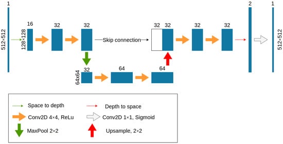
Figure 1.
Architecture of HoloLightNet-Mini, a neural network for computer-generated hologram reconstruction.
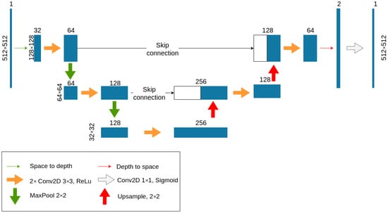
Figure 2.
Architecture of HoloLightNet, a neural network for digital hologram reconstruction.
While HoloLightNet-Mini has a depth of one (only one level of nesting and a minimum of skip connections), the depth of HoloLightNet was increased to three, so it has approximately 5 million trainable parameters. This allows it to extract a larger number of features from digital holograms and increases its ability to adapt to different optical distortions present in optically registered holograms.
Several datasets consisting of 10,000 pairs of QR codes and corresponding computer-generated or optically registered Fresnel holograms were created for training. QR codes of versions 2–11 [70] (initial sizes vary from 25 × 25 pixels to 61 × 61 pixels) with error correction degree H (30%) were used. The different versions of QR code represent their spatial heterogeneity: the higher the version of a QR code, the more complex its spatial structure. These QR codes were then rescaled to 64 × 64, 128 × 128, 256 × 256, and 512 × 512 pixels. To avoid distortions, QR codes were enlarged without interpolation to the nearest size and then padded with black borders. Additional information about QR codes can be found in Appendix A.
2.2. Training Datasets for Computer-Generated Holograms (HoloLightNet-Mini)
The first training dataset consists of computer-generated holograms and object images (QR codes). The holograms were generated by calculating the Fresnel–Kirchhoff integral in the Fresnel approximation [38] for the inline hologram (which corresponds to the physical setup that was used for subsequent optical experiments):
where A(x, y, 0)—object field, (x, y)—coordinates in the object plane, (u, v)—coordinates in the hologram plane, λ—light wavelength, FFT{}—fast Fourier transform, z is distance between object and hologram planes, and A(u, v, z)—object beam (complex amplitude of the object field in the hologram plane). The intensity of the reference beam was calculated as the average intensity over the object field in the hologram plane. The amplitude of the reference beam was chosen as follows:
where ⟨ ⟩ denotes the averaging operation.
The generated hologram is the total intensity distribution at a given distance z:
The light wavelength λ is equal to 532 nm. The pixel size of the modeled SLM is 3.74 × 3.74 μm. These parameters were chosen based on our digital hologram registration setup.
Using Equations (1)–(3), a phase-only inline Fresnel holograms were generated for each rescaled QR code. The resolution of holograms matched the resolution of the QR codes. Examples of generated holograms and their corresponding QR codes will be shown in Section 3.1.
Additionally, a set of computer-generated holograms with the emulated noise of a digital camera and optical speckle noise was generated. The following additive noise model was used: random noise with a fixed standard deviation of 0.1 was added to the holograms. The value of the deviation was chosen according to the average level of noise distortion occurring in typical optical setups. An additive noise is not the only source of distortion in digital holograms (for example, hardware nonlinearities or laser intensity fluctuations can also have an impact). But it is a consistent source of distortion between different optical setups. Instead of modeling additional types of noise we used real optically registered holograms to create an additional training dataset (Section 3.4). Examples of generated holograms and their corresponding QR codes will be shown in Section 3.2 and Section 3.3. These datasets can be found in [75].
2.3. Training Datasets for Digital Holograms (HoloLightNet)
The optical setup used for the registration of inline digital holograms is shown in Figure 3. A Nd:YAG laser #1 operating in the second harmonic emission mode, with a wavelength of 532 nm and maximum power of 200 mW was used. After passing through the beam expansion system #2–4, the laser beam was divided into the object and the reference beams by a beam splitter #6. The object beam was directed to the phase-only liquid crystal on silicon (LCoS) SLM HoloEye GAEA-2.1 #75 (pixel size 3.74 µm × 3.74 µm, matrix resolution 4160 × 2464 pixels), which displayed the QR code images. The reference beam, which was a plane wave, was reflected from a blind mirror #5. Both beams overlapped on a Flare 48MP digital camera #8 (pixel size 4.6 µm × 4.6 µm, matrix resolution 7920 × 6004 pixels), which registered the interference pattern they created (digital hologram).
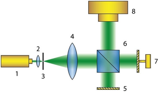
Figure 3.
Schematic of the optical setup for digital hologram registration: 1—laser, 2–4—beam expansion system, 5—blind mirror, 6—beam splitter, 7—phase-only SLM, 8—digital camera.
It is important to underline that optically registered digital holograms differ from computer-generated ones (even if noise was taken into account during their creation) due to the presence of a large number of optical distortions. The final registered hologram is negatively affected by fluctuations of laser intensity, imperfect matching of the reference and object beams, roughness of optical elements [76], etc. This leads to significant complications during the reconstruction process. The datasets of the registered digital holograms and original QR code images can be found in [75].
2.4. Training Procedure
The modified neural networks were trained using the mini-batch gradient descent procedure. The QR code is a binary image, so the sigmoid activation function was used in the last layer, which maps the output into the interval from 0 to 1. Consequently, the value returned by the neural network in an individual pixel can be interpreted as the probability of a pixel belonging to the first class (which corresponds to value “1” or white pixel).
Based on the maximum likelihood principle in combination with the sigmoid layer, it is optimal to use average binary cross entropy over the whole image as a loss function [77]:
where Ai,j, Bi,j are the images being compared, i, j are the pixel indices.
To avoid overfitting, the training was stopped when the difference between the error for the training and validation sets stopped changing (or increased) after several epochs. Both developed networks were trained using this algorithm.
3. Results
The trained HoloLightNet-Mini was validated on three different numerical reconstruction cases:
- Reconstruction of different versions of QR codes from holograms generated without additional noise. This scenario allows us to estimate the maximum achievable reconstruction quality under ideal conditions.
- Reconstruction of different versions of QR codes from holograms generated with additional noise. This scenario simulates the holograms’ registration in a real optical setup.
- Reconstruction of the fixed-version QR code from holograms generated with additional noise. This scenario evaluates the performance of neural network reconstruction when it is not affected by variation in QR code complexity.
The trained HoloLightNet was validated on optically registered digital holograms.
The bit error rate (BER) value [78] was used as a numerical quality metric for the reconstructed QR codes:
where Nerror is the number of incorrect pixels in the reconstructed QR code and Ntotal is the total number of QR code pixels. BER was calculated after the binarization of the reconstructed QR codes. For binary images, the BER is equivalent to the percentage of incorrect pixels in the reconstructed image.
BER was chosen as our main metric due to the binary and quasirandom nature of QR codes. QR codes contain consistently structured elements (function patterns). However, the most important and hard-to-reconstruct information is contained in an encoding region, which is binary data similar in appearance to salt-and-pepper noise. Therefore, to better analyze the quality of the reconstructed QR codes, we need a pixel-by-pixel metric, specialized for binary images. BER allows us to see the percentage of incorrect pixels in reconstructed QR codes. When taking QR code error correction into account, it provides a good insight into the overall quality of the reconstructed QR codes and whether they can be decoded or not.
3.1. Computer Holograms Generated Without Additional Noise
Firstly, holograms were generated without additional noise, according to Equations (1)–(3). After training the neural network, its performance was evaluated on test holograms that were not part of the training dataset.
Figure 4 shows the QR codes reconstructed by HoloLightNet-Mini for this case. Column 1 (a, e, i, m) shows computer-generated Fresnel holograms. Column 2 (b, f, j, n) shows the corresponding images of version 5 QR codes ((b)—64 × 64 counts, (f)—128 × 128, (j)—256 × 256, (n)—512 × 512). Column 3 (c, g, k, o) shows QR codes reconstructed from holograms by the trained network. Column 4 (d, h, l, p) visualizes error distribution maps. Red pixels correspond to false white pixels and blue pixels correspond to false black pixels. BERs are equal to 11.4% (d), 7.1% (h), 3.4% (l), and 0.6% (p). The placements of incorrect pixels are random, therefore a BER value of 4% was used as the threshold for guaranteed decoding of the QR code (see Appendix A).
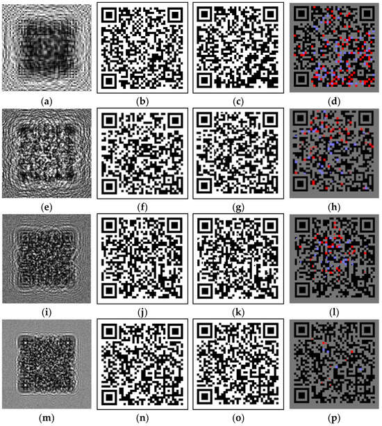
Figure 4.
HoloLightNet-Mini image reconstruction from the noiseless computer-generated holograms: computer-generated holograms (a,e,i,m), enlarged ideal QR codes (b,f,j,n), QR codes reconstructed by the HoloLightNet-Mini (c,g,k,o), and error distribution maps (red pixels correspond to false white pixels and blue pixels correspond to false black pixels) (d,h,l,p). The sizes of the enlarged QR codes are: 64 × 64 pixels (b–d); 128 × 128 pixels (f–h); 256 × 256 pixels (j–l); 512 × 512 pixels (n–p). Training dataset contained QR codes of different versions.
For each QR code resolution, HoloLightNet-Mini performance was statistically analyzed. Figure 5 shows the correlation between the BER values and the versions of the QR codes at fixed resolution values. The horizontal dotted line indicates the 4% threshold of guaranteed decoding. The error was calculated statistically, using the standard deviation for the entire test sample of 1000 objects that were not used during the training process.
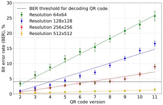
Figure 5.
Correlation between the reconstructed QR code BER value and the QR code version for HoloLightNet-Mini at different QR code resolutions. Noiseless holograms, training dataset contained QR codes of different versions.
Based on values demonstrated in Figure 5, it can be said that:
- The BER values decreased exponentially with the increase in QR code resolution.
- The BER values increased linearly with the QR code version.
It should be added that the results were obtained with the HoloLightNet-Mini which has only about 200 thousand trainable parameters. Even such a lightweight neural network is able to achieve a high quality of reconstruction for computer-generated holograms. For a hologram with a resolution of 512 × 512 pixels, the average BER was (1.4 ± 0.4)%, which is lower than a half of the guaranteed recognition threshold of 4%. At the same time, the reconstruction time for one hologram for HoloLightNet-Mini was only 0.3 ms, which is more than two orders of magnitude lower than the original U-Net architecture in the same conditions.
3.2. Noisy Computer-Generated Holograms with Variation in QR Code Complexity
Optically registered digital holograms are inevitably contaminated with different types of optical noise, the main ones being speckle noise and camera noise [57]. To evaluate the performance of HoloLightNet-Mini in more realistic conditions, the network was trained on computer-generated holograms with added noise.
Figure 6 demonstrates the QR code reconstruction by HoloLightNet-Mini. The arrangement of the elements is similar to Figure 4. Column 1 (a, e, i, m) shows noisy computer-generated Fresnel holograms. Column 2 (b, f, j, n) shows the corresponding version 5 QR codes used to generate holograms ((b)—64 × 64 counts, (f)—128 × 128, (j)—256 × 256, (n)—512 × 512). Column 3 (c, g, k, o) shows QR codes reconstructed by the trained HoloLightNet-Mini. Column 4 (d, h, l, p) visualizes error distribution maps. Red pixels correspond to false white pixels and blue pixels correspond to false black pixels. BERs are equal to 20.8% (d), 7.8% (h), 3.8% (l), and 1.1% (p). The correlation between the BER value and the version of the QR codes is shown in Figure 7.
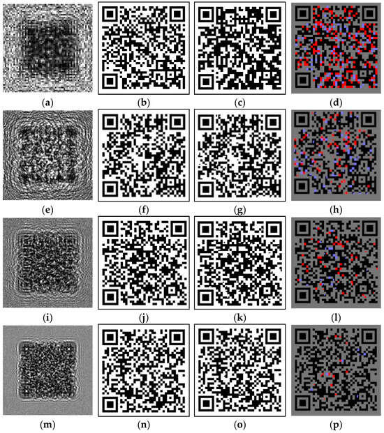
Figure 6.
HoloLightNet-Mini image reconstruction from the noisy generated holograms: noisy computer-generated holograms (a,e,i,m), enlarged ideal QR codes (b,f,j,n), QR codes reconstructed by the HoloLightNet-Mini (c,g,k,o), and error distribution maps (red pixels correspond to false white pixels and blue pixels correspond to false black pixels) (d,h,l,p). The sizes of the enlarged QR codes are: 64 × 64 pixels (b–d); 128 × 128 pixels (f–h); 256 × 256 pixels (j–l); 512 × 512 pixels (n–p). Training dataset contained QR codes of different versions.
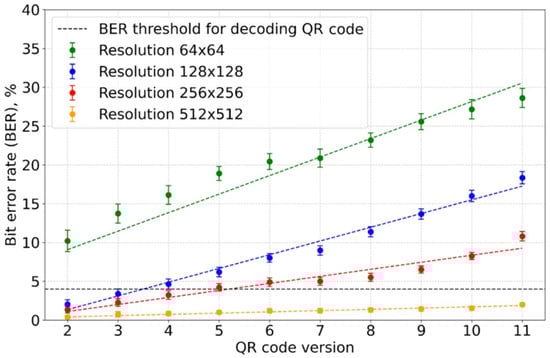
Figure 7.
Correlation between the reconstructed QR code BER value and the QR code version for HoloLightNet-Mini at different QR code resolutions. Holograms with additional noise, training dataset contained QR codes of different versions.
The noise has a significant negative impact on the performance of the neural network. The number of errors increases much faster with the QR code version when compared to the noiseless holograms. Even for relatively simple QR codes (small version numbers) BER values often exceed the threshold for successful decoding. This is especially pronounced for 64 × 64 QR codes, where all the BER values exceed the threshold, making them unsuitable for practical use.
3.3. Noisy Computer-Generated Holograms Without Variability in QR Code Complexity
In the two previous sections the training dataset contained QR codes of different versions (from 2 to 11). This allowed us to evaluate the performance of HoloLightNet-Mini for reconstruction of images with different degrees of spatial heterogeneity. However, when the network works with holograms of similar objects, this diversity may be excessive. To evaluate the performance of HoloLightNet-Mini for images of fixed complexity, it was trained on a dataset consisting of only version 7 QR codes and their corresponding computer-generated holograms with additional noise.
Figure 8 demonstrates the QR code reconstruction by HoloLightNet-Mini. The arrangement of the elements is similar to Figure 4 and Figure 6. Column 1 (a, e, i, m) shows noisy computer-generated Fresnel holograms of QR codes. Column 2 (b, f, j, n) shows the corresponding QR codes used to generate holograms ((b)—64 × 64 counts, (f)—128 × 128, (j)—256 × 256, (n)—512 × 512). Column 3 (c, g, k, o) shows QR codes reconstructed from holograms by the trained HoloLightNet-Mini. Column 4 (d, h, l, p) visualizes error distribution maps, where red pixels correspond to false white pixels and blue pixels correspond to false black pixels. BERs are equal to 16.1% (d), 5.8% (h), 3.8% (l), and 1.2% (p). The correlation between the BER value and the version of the QR codes is shown in Figure 7.
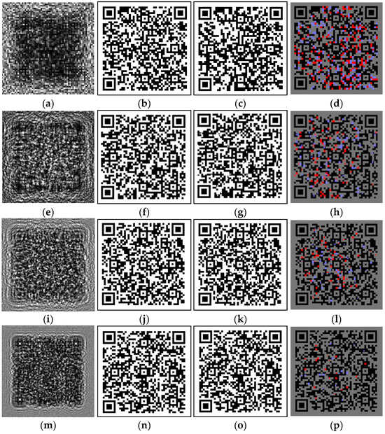
Figure 8.
HoloLightNet-Mini image reconstruction from the noisy generated holograms: noisy computer-generated holograms (a,e,i,m), enlarged ideal QR codes (b,f,j,n), QR codes reconstructed by the HoloLightNet-Mini (c,g,k,o), and error distribution maps (red pixels correspond to false white pixels and blue pixels correspond to false black pixels) (d,h,l,p). The sizes of the enlarged QR codes are: 64 × 64 pixels (b–d); 128 × 128 pixels (f–h); 256 × 256 pixels (j–l); 512 × 512 pixels (n–p). Training dataset contained only version 7 QR codes.
The correlation between the BER value and the QR code resolution is shown in Figure 9. The same correlation for the training dataset containing different QR code versions is given for comparison. A more specialized training dataset improves the quality of the reconstructed images. In this case, the 256 × 256 resolution is sufficient for guaranteed QR code decoding, i.e., the size of the corresponding holograms can be reduced by four times, which reduces the memory and computational load required for their storage and processing.
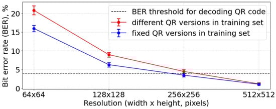
Figure 9.
Correlation between the BER value and the QR code resolution. Training dataset contained only fixed version 7 QR codes.
3.4. Image Reconstruction from Digital Holograms
The HoloLightNet architecture was trained and tested on optically registered inline Fresnel holograms. Version 2 QR codes enlarged to 512 × 512 pixels were displayed onto SLM as objects during hologram registration.
Figure 10 shows examples of test holograms and the QR codes, reconstructed by the trained HoloLightNet. Column 1 (a, e, i) shows the optically registered digital holograms. Column 2 (b, f, j) shows the corresponding QR codes. Column 3 (c, g, k) shows the QR codes reconstructed from the holograms by the trained HoloLightNet after 2, 5, and 20 epochs, respectively. Column 4 (d, h, l) contains error distribution maps, where red pixels correspond to false white pixels and blue pixels correspond to false black pixels. BERs are equal to 16.0% (d), 4.5% (h), and 1.2% (l).
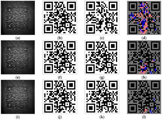
Figure 10.
HoloLightNet image reconstruction from the optically registered digital holograms: holograms (a,e,i), enlarged ideal QR codes (b,f,j), QR codes reconstructed by the HoloLightNet (c,g,k), and error distribution maps (red pixels correspond to false white pixels and blue pixels correspond to false black pixels) (d,h,l). The training dataset contained version 7 QR codes. The HoloLightNet was trained for 2 (c–d), 5 (g–h), and 20 (k–l) epochs.
The average BER was (3.0 ± 1.0)% which guarantees successful QR code decoding. The time of reconstruction from an optically registered digital hologram using HoloLightNet was only 3 ms. For reference, the method of high-quality image reconstruction presented in [40] takes up to tens of seconds. Thus, even heavier HoloLightNet architecture is still more than 1000 times faster than more traditional neural-network-based algorithms.
In order to compare, the HoloLightNet-Mini architecture (200K parameters) and two other networks were trained, these were the pre-trained MobileNet (3.5M parameters) [79] and MiT-b0 (3M parameters) [80] models, used as the encoder. These networks provided good results in their generated data. Results for the HoloLightNet-Mini architecture are given in Section 3.1, Section 3.2 and Section 3.3. Average BERs for the MobileNet and MiT-b0 were 0.5% and 1.2%, respectively. However, the number of parameters in these networks is 15 and 17.5 times higher than the HoloLightNet-Mini.
Examples of QR codes reconstructed from the optically registered digital holograms by the three aforementioned models are shown in Figure 11b–d. It is important to note that the performance of the pre-trained models is notably inferior to the performance of the proposed HoloLightNet (Figure 10k).
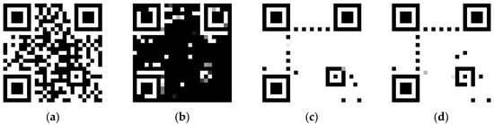
Figure 11.
Image reconstruction from the optically registered digital holograms: original QR (a), HoloLightNet-Mini (b), networks with MobileNet (c), and MiT-b0 (d).
The average BER for HoloLightNet-mini, MobileNet, and MiT-b0 was (31 ± 1)%. The performance of the HoloLightNet-mini falls short of the HoloLightNet due to its relatively lower number of trainable parameters. The low performance of the pre-trained models may be attributed to them being trained on a general image dataset, which may not align with the specific requirements of holographic image reconstruction. Additional data is likely necessary for further fine-tuning. We assume that the difference between the quality of the numerical and optical values for the MobileNet and MiT-b0 was due to changes occurring during the optical recording of the holograms. There are factors that contribute to this difference, such as aberrations, photosensor noise, stray light, etc. To estimate which factor contributes the most to this difference, additional detailed research is required.
4. Discussion
In this paper we have demonstrated that high-quality holographic image reconstruction can be achieved using neural networks with much fewer trainable parameters when compared to commonly used ones. The developed architectures HoloLightNet-Mini (approximately 200 thousand trainable parameters) and HoloLightNet (approximately 5 million trainable parameters) provided sufficient reconstruction quality for successful QR code decoding.
The results show that the quality reconstruction of spatially heterogeneous objects heavily depends on the size of the holograms used for network training. The optimal resolution, in turn, is determined by the balance of many factors: the available equipment (primarily the camera and the SLM), the required speed and bandwidth of the system, and the amount of data. Although, on the one hand, modern cameras can have resolutions of tens of megapixels, from the point of view of increasing throughput, it is more efficient to use holograms of smaller sizes but with higher output frequency.
HoloLightNet-Mini and HoloLightNet can successfully extract information from holograms of binary data containers even when the corresponding holograms are relatively small: 256 × 256 pixels in the case of computer-generated holograms and 512 × 512 pixels in the case of optically registered digital holograms. At these resolutions modern cameras can achieve a registration rate of tens of kHz, which corresponds to a bandwidth of up to tens of Gbit/s.
The use of lightweight neural network architecture for hologram reconstruction does not significantly compromise the quality of image recovery. Still, finding the optimal network structure that provides the best balance between the reconstruction quality and speed is a promising direction for future research.
HoloLightNet-Mini and HoloLightNet were trained on a commercially available laptop with NVIDIA GeForce RTX 3050Ti GPU and still demonstrated reconstruction speeds of fractions of ms. The use of more advanced hardware or specialized processors designed for neural networks will further reduce training and reconstruction time. In the future, joint optimization of optical and digital systems will make it achievable to implement a real-time holographic reconstruction system.
5. Conclusions
We investigated the applicability of lightweight neural networks for holographic reconstruction of spatially inhomogeneous objects that are represented by binary data containers (QR codes). Two modifications of the U-Net architecture were developed: HoloLightNet-Mini (designed for computer-generated holograms) and HoloLightNet (designed for optically registered digital holograms).
Based on statistical generalization of the HoloLightNet-Mini’s performance, it was shown that the quality of the reconstructed images exponentially degraded with decreases of the resolution. On the other hand, the BER value increased linearly as the version of the QR code decreased (at a fixed resolution). HoloLightNet-Mini achieved a 1.4% rate of errors, which is below the threshold of guaranteed successful decoding, which is 4%.
The second network modification, the HoloLightNet, was developed to reconstruct optically registered digital holograms. It was tested on a set of optically registered digital holograms of version 2 QR codes. The BER value was 1.2% for holograms of 512 × 512 pixels, so decoding was successful in this case too.
These results have high practical significance, because the development of new methods of fast and efficient holographic image reconstruction is an important task in holography. This paper demonstrates that neural network-based methods can reconstruct both homogeneous and inhomogeneous object images orders of magnitude faster than traditional methods without sacrificing the image quality. The substantial simplification of the U-Net architecture demonstrated in this paper allows for more efficient use of computational resources when compared to the original architecture.
The results can be used for data storage, optical communication and encryption, fast and accurate information recovery, etc., and for other image reconstruction techniques, like coherent diffraction imaging, ptychography, lensless imaging, compressed sensing, etc.
Author Contributions
Conceptualization, E.Y.Z., N.N.E. and R.S.S.; methodology, P.A.C., A.V.S. and R.S.S.; software, M.K.D., D.A.R., A.S.S. and S.A.K.; validation, M.K.D., D.A.R., A.V.S. and S.A.K.; formal analysis, E.Y.Z., E.K.P. and V.A.N.; investigation, M.K.D., D.A.R., A.S.S., P.A.C., A.V.S. and S.A.K.; resources, N.N.E.; data curation, E.K.P. and V.A.N.; writing—original draft preparation, M.K.D., D.A.R., P.A.C. and A.V.S.; writing—review and editing, M.K.D., P.A.C. and A.V.S.; visualization, M.K.D. and A.V.S.; supervision, R.S.S.; project administration, P.A.C. and N.N.E.; funding acquisition, R.S.S. All authors have read and agreed to the published version of the manuscript.
Funding
This work was supported by grant 23-12-00336 from the Russian Science Foundation (RSF).
Institutional Review Board Statement
Not applicable.
Informed Consent Statement
Not applicable.
Data Availability Statement
The original data presented in the study are openly available in “QR code reconstruction” at https://github.com/k1121/qrcode-reconstruction (accessed on 15 October 2025).
Conflicts of Interest
The authors declare no conflicts of interest.
Abbreviations
The following abbreviations are used in this manuscript:
| BER | Bit error rate |
| QR | Quick response |
| SLM | Spatial light modulator |
| LCoS | liquid crystal on silicon |
Appendix A
QR Codes in Holographic Applications
The amount of information that can be stored in one QR code depends on its version and the chosen degree of error correction. The standard [70] defines 40 versions of QR codes with data capacities of 9 bytes to approximately 3 kilobytes and 4 variants of correction rate: 7%, 15%, 25%, and 30%. Figure A1 shows several QR codes of different versions at a fixed final image resolution (512 × 512 pixels).

Figure A1.
Examples of QR codes of different versions: version 2 (a), version 6 (b), and version 12 (c).
Figure A1.
Examples of QR codes of different versions: version 2 (a), version 6 (b), and version 12 (c).

The degree of error correction determines the volume of redundant information required to decode the original data in case of partial damage or distortion of the QR code. The higher the error correction is, the higher the probability of successful decoding in case of QR code damage, however the amount of data that can be stored decreases.
QR codes use Reed–Solomon error-correction code, which operates on bytes: the minimum unit of information is 1 byte (8 bits). On the other hand, QR codes are binary images. Consequently, to represent 1 byte of information graphically, a group of 8 pixels is needed. This group is organized into a 2 × 4 block, and the areas not occupied by the service elements of the QR code are filled with these blocks. However, even one incorrect pixel in the block leads to the whole block being considered erroneous. The degree of error correction for the QR code is specified in relation to the number of 8-pixel blocks. Thus, the true value of the maximum erroneous bits (pixels) depends on the distribution of errors in the QR code. The more evenly distributed the errors are, the lower the threshold for successful decoding. Figure A2 shows two QR codes with the same number of errors and different distributions. In the first one, the fraction of damaged blocks (and thus the minimum required degree of correction) is 25%, in the second one—only 15%.

Figure A2.
The error distribution map for the QR code (incorrect pixels are marked in red; correct pixels are marked in green): uniform distribution (a) and localized distribution (b).
Figure A2.
The error distribution map for the QR code (incorrect pixels are marked in red; correct pixels are marked in green): uniform distribution (a) and localized distribution (b).

In case of completely uniform distribution (which is typical for coherent optical systems since both speckle noise and camera noise evenly affect the whole matrix) it can be evaluated as the selected degree of correction divided by eight.
References
- Khodadad, D. Digital Holography and Its Application. Appl. Sci. 2024, 14, 11254. [Google Scholar] [CrossRef]
- Ferraro, P.; Alieva, T.; Memmolo, P.; Nehmetallah, G.; Zhang, Y. Recent breakthroughs in digital holography, 2D/3D imaging, and holographic optical elements: Introduction. J. Opt. Soc. Am. 2025, 64, DH1–DH2. [Google Scholar] [CrossRef] [PubMed]
- Tiwari, V.; Gopinath, S.; Kahro, T.; Arockiaraj, F.G.; Ignatius Xavier, A.P.; Joshi, N.; Kukli, K.; Tamm, A.; Juodkazis, S.; Rosen, J.; et al. Recent Advances in Spatially Incoherent Coded Aperture Imaging Technologies. Technologies 2025, 13, 210. [Google Scholar] [CrossRef]
- Tahara, T.; Shimobaba, T.; Kozawa, Y. Review on imaging and sensing with holography. J. Opt. 2025, 27, 043005. [Google Scholar] [CrossRef]
- Shi, Q. The Breakthrough of Holographic Projection Technology in Stage Art Front. Front. Art Res. 2025, 7, 100–104. [Google Scholar] [CrossRef]
- Rameez, A.; Hidayat, K.; Shakil, A. Revolutionary Hologram Systems: Pioneering a New Frontier in Visual Technology. Int. J. Innov. Sci. Technol. 2024, 6, 1943–1955. [Google Scholar]
- Haleem, A.; Javaid, M.; Khan, I.H. Holography applications toward medical field: An overview. Indian J. Radiol. Imaging 2020, 30, 354–361. [Google Scholar] [CrossRef]
- Kumar, M.; Murata, T.; Matoba, O. Live Cell Imaging by Single-Shot Common-Path Wide Field-of-View Reflective Digital Holographic Microscope. Sensors 2024, 24, 720. [Google Scholar] [CrossRef]
- Dyomin, V.; Polovtsev, I.; Davydova, A.; Kirillov, N. Spectroscopic aspects of underwater digital holography of plankton. Sci. Rep. 2025, 15, 1884. [Google Scholar] [CrossRef]
- Reztsov, T.V.; Chernykh, A.V.; Orlova, T.; Petrov, N.V. A Dynamic Analysis of Toron Formation in Chiral Nematic Liquid Crystals Using a Polarization Holographic Microscope. Polymers 2025, 17, 1849. [Google Scholar] [CrossRef] [PubMed]
- Hesselink, L.; Orlov, S.S.; Bashaw, M.C. Holographic data storage systems. Proc. IEEE 2004, 92, 1231–1280. [Google Scholar] [CrossRef]
- Minikhanov, T.Z.; Zlokazov, E.Y.; Cheremkhin, P.A.; Starikov, R.S.; Evtikhiev, N.N. Computer-Generated Holography Methods for Data Page Reconstruction Using Phase-Only Medium. Appl. Sci. 2023, 13, 4479. [Google Scholar] [CrossRef]
- Blanche, P.-A. Holography, and the future of 3D display. Light Adv. Manuf. 2021, 2, 446–459. [Google Scholar] [CrossRef]
- Pi, D.; Liu, J.; Wang, Y. Review of computer-generated hologram algorithms for color dynamic holographic three-dimensional display. Light Sci. Appl. 2022, 11, 231. [Google Scholar] [CrossRef]
- Kishk, S.; Javidi, B. Watermarking of by digital three-dimensional objects holography. Opt. Lett. 2003, 28, 167. [Google Scholar] [CrossRef] [PubMed]
- Chen, C.; Wei, Y.; Zhang, H.; Zhuang, Z.; Li, Z.; Shen, C.; Zhang, J.; Cai, H.; Chi, N.; Shi, J. Spatial Multiplexing Holography for Multi-User Visible Light Communication. Photonics 2025, 12, 160. [Google Scholar] [CrossRef]
- Sachin; Kumar, R.; Sakshi; Yadav, R.; Reddy, S.G.; Yadav, A.K.; Singh, P. Advances in Optical Visual Information Security: A Comprehensive Review. Photonics 2024, 11, 99. [Google Scholar] [CrossRef]
- Collier, R.J.; Burckhardt, C.B.; Lin, L.H. Optical Holography; Elsevier: Amsterdam, The Netherlands, 1971. [Google Scholar] [CrossRef]
- Schnars, U.; Jüptner, W. Digital Holography; Springer: Berlin/Heidelberg, Germany, 2005. [Google Scholar] [CrossRef]
- Sahin, E.; Stoykova, E.; Mäkinen, J.; Gotchev, A. 2021 Computer-Generated Holograms for 3D Imaging. ACM Comput. Surv. 2020, 53, 1–35. [Google Scholar] [CrossRef]
- Matsushima, K.; Arima, Y.; Nakahara, S. Digitized holography: Modern holography for 3D imaging of virtual and real objects. Appl. Opt. 2011, 50, H278. [Google Scholar] [CrossRef]
- Cuche, E.; Marquet, P.; Depeursinge, C. Spatial filtering for zero-order and twin-image elimination in digital off-axis holography. Appl. Opt. 2000, 39, 4070–4075. [Google Scholar] [CrossRef]
- Stoykova, E.S.E.; Kang, H.K.H.; Park, J.P.J. Twin-image problem in digital holography—A survey. Chin. Opt. Lett. 2014, 12, 060013-1–060013-12. [Google Scholar] [CrossRef]
- Arcab, P.; Rogalski, M.; Trusiak, M. Single-shot experimental-numerical twin-image removal in lensless digital holographic microscopy. Opt. Lasers Eng. 2024, 172, 107878. [Google Scholar] [CrossRef]
- Kozlov, A.V.; Cheremkhin, P.A.; Svistunov, A.S.; Rodin, V.G.; Starikov, R.S.; Evtikhiev, N.N. Interpolation-Filtering Method for Image Improvement in Digital Holography. Appl. Sci. 2024, 14, 8790. [Google Scholar] [CrossRef]
- Kim, J.; Lee, S.J. Digital in-line holographic microscopy for label-free identification and tracking of biological cells. Mil. Med. Res. 2024, 11, 38. [Google Scholar] [CrossRef] [PubMed]
- Picazo-Bueno, J.A.; Ketelhut, S.; Schnekenburger, J.; Micó, V.; Kemper, B. Off-axis digital lensless holographic microscopy based on spatially multiplexed interferometry. J. Biomed. Opt. 2024, 29, s22715. [Google Scholar] [CrossRef]
- Dufresne, E.R.; Spalding, G.C.; Dearing, M.T.; Sheets, S.A.; Grier, D.G. Computer-generated holographic optical tweezer arrays. Rev. Sci. Instrum. 2001, 72, 1810. [Google Scholar] [CrossRef]
- Liu, X.; Hu, Y.; Tu, S.; Kuang, C.; Liu, X.; Hao, X. Fast generation of arbitrary optical focus array. Opt. Lasers Eng. 2023, 162, 107405. [Google Scholar] [CrossRef]
- Wen, H.; Yang, L.; Bai, C.; Lin, Y.; Liu, T.; Chen, L.; Hu, Y.; He, D. Exploiting high-quality reconstruction image encryption strategy by optimized orthogonal compressive sensing. Sci. Rep. 2024, 14, 8805. [Google Scholar] [CrossRef]
- Chaudhary, H.; Garg, P.; Vishwakarma, V.P. Enhanced medical image watermarking using hybrid DWT-HMD-SVD and Arnold scrambling. Sci. Rep. 2025, 15, 9710. [Google Scholar] [CrossRef]
- Hassanzadeh, K.; Ahmadi-Kandjani, S.; Kheradmand, R.; Mortazavi, S.A. Approach to optical encryption: Merging ghost imaging with chaos theory. Opt. Express 2025, 33, 28301–28319. [Google Scholar] [CrossRef]
- Meteyer, E.; Pezerat, C.; Picart, P. Decorrelation and anti-correlation from defocus in digital holographic interferometry. J. Opt. Soc. Am. A 2023, 40, b33–b46. [Google Scholar] [CrossRef] [PubMed]
- Qi, Z.; Liang, W. Numerical Simulations of Single-Step Holographic Interferometry for Split-Ring Metamaterial Fabrication. Nanomaterials 2025, 15, 86. [Google Scholar] [CrossRef]
- Evtikhiev, N.N.; Zlokazov, E.Y.; Krasnov, V.V.; Rodin, V.G.; Starikov, R.S.; Cheremkhin, P.A. High-speed implementation of holographic and diffraction elements using digital micromirror devices. Quantum Electron. 2020, 50, 667–674. [Google Scholar] [CrossRef]
- Rhisheekesan, A.; Thomas, D.; Ulahannan, J.P.; Damodarakurup, S. Review on digital holography techniques using digital micromirror device. Opt. Lasers Eng. 2024, 177, 108120. [Google Scholar] [CrossRef]
- Huang, Z.; Cao, L. Quantitative phase imaging based on holography: Trends and new perspectives. Light: Sci. Appl. 2024, 13, 145. [Google Scholar] [CrossRef]
- Goodman, J.W. Introduction to Fourier Optics, 3rd ed.; Roberts & Co.: Greenwood Village, CO, USA, 2005. [Google Scholar]
- Latychevskaia, T. Iterative phase retrieval for digital holography: Tutorial. J. Opt. Soc. Am. 2019, 36, D31–D40. [Google Scholar] [CrossRef] [PubMed]
- Rivenson, Y.; Zhang, Y.; Günaydın, H.; Teng, D.; Ozcan, A. Phase recovery and holographic image reconstruction using deep learning in neural networks. Light Sci. Appl. 2018, 7, 17141. [Google Scholar] [CrossRef] [PubMed]
- González-Santoyo, C.; Renza, D.; Moya-Albor, E. Identifying and Mitigating Label Noise in Deep Learning for Image Classification. Technologies 2025, 13, 132. [Google Scholar] [CrossRef]
- Lindsay, M.; Kovaleski, S.D.; Veal, C.; Anderson, D.T.; Price, S.R. Machine learning assisted holography. Proc. Comput. Imaging VI 2021, 11731, 2. [Google Scholar] [CrossRef]
- Zhu, Y.; Huang, M.; Zhu, Y.; Jiang, J.; Zhang, Y. HDF-Net: Hierarchical Dual-Branch Feature Extraction Fusion Network for Infrared and Visible Image Fusion. Sensors 2025, 25, 3411. [Google Scholar] [CrossRef]
- Jiayi, Q.; Yansong, J.; Yiping, C.; Haitao, W. Single-shot phase-shifting composition fringe projection profilometry by multi-attention fringe restoration network. Neurocomputing 2025, 634, 129908. [Google Scholar] [CrossRef]
- Kazanskiy, N.L.; Khonina, S.N.; Oseledets, I.V.; Nikonorov, A.V.; Butt, M.A. Revolutionary Integration of Artificial Intelligence with Meta-Optics-Focus on Metalenses for Imaging. Technologies 2024, 12, 143. [Google Scholar] [CrossRef]
- Thakur, G.K.; Thakur, A.; Kulkarni, S.; Khan, N.; Khan, S. Deep Learning Approaches for Medical Image Analysis and Diagnosis. Cureus 2024, 16, e59507. [Google Scholar] [CrossRef] [PubMed]
- Zuo, C.; Qian, J.; Feng, S.; Yin, W.; Li, Y.; Fan, P.; Han, J.; Qian, K.; Chen, Q. Deep learning in optical metrology: A review. Light Sci. Appl. 2022, 11, 39. [Google Scholar] [CrossRef]
- Reyes-Vera, E.; Valencia-Arias, A.; García-Pineda, V.; Aurora-Vigo, E.F.; Alvarez Vásquez, H.; Sánchez, G. Machine Learning Applications in Optical Fiber Sensing: A Research Agenda. Sensors 2024, 24, 2200. [Google Scholar] [CrossRef]
- Lininger, A.; Aththanayake, A.; Boyd, J.; Ali, O.; Goel, M.; Jizhe, Y.; Hinczewski, M.; Strangi, G. Machine learning to optimize additive manufacturing for visible photonics. Nanophotonics 2023, 12, 2767–2778. [Google Scholar] [CrossRef]
- Fu, T.; Zhang, J.; Sun, R.; Huang, Y.; Xu, W.; Yang, S.; Zhu, Z.; Chen, H. Optical neural networks: Progress and challenges. Light: Sci. Appl. 2024, 13, 263. [Google Scholar] [CrossRef]
- Hadad, B.; Froim, S.; Yosef, E.; Giryes, R.; Bahabad, A. Deep learning in optics-a tutorial. J. Opt. 2023, 25, 123501. [Google Scholar] [CrossRef]
- Zeng, T.; Zhu, Y.; Lam, E.Y. Deep learning for digital holography: A review. Opt. Express 2021, 29, 40572. [Google Scholar] [CrossRef]
- Situ, G. Deep holography. Light. Adv. Manuf. 2022, 3, 278–300. [Google Scholar] [CrossRef]
- Cheremkhin, P.A.; Rymov, D.A.; Svistunov, A.S.; Zlokazov, E.Y.; Starikov, R.S. Neural-network—based methods in digital and computer-generated holography: A review. J. Opt. Technol. 2024, 91, 170. [Google Scholar] [CrossRef]
- Montresor, S.; Tahon, M.; Picart, P. Deep learning speckle de-noising algorithms for coherent metrology: A review and a phase-shifted iterative scheme [Invited]. J. Opt. Soc. Am. A 2022, 39, A62. [Google Scholar] [CrossRef] [PubMed]
- Wang, K.; Dou, J.; Kemao, Q.; Di, J.; Zhao, J. Y-Net: A one-to-two deep learning framework for digital holographic reconstruction. Opt. Lett. 2019, 44, 4765. [Google Scholar] [CrossRef]
- Svistunov, A.S.; Rymov, D.A.; Starikov, R.S.; Cheremkhin, P.A. HoloForkNet: Digital Hologram Reconstruction via Multibranch Neural Network. Appl. Sci. 2023, 13, 6125. [Google Scholar] [CrossRef]
- Chen, B.; Li, Z.; Zhou, Y.; Zhang, Y.; Jia, J.; Wang, Y. Deep-Learning Multiscale Digital Holographic Intensity and Phase Reconstruction. Appl. Sci. 2023, 13, 9806. [Google Scholar] [CrossRef]
- Kiriy, S.A.; Rymov, D.A.; Svistunov, A.S.; Shifrina, A.V.; Starikov, R.S.; Cheremkhin, P.A. Generative adversarial neural network for 3D-hologram reconstruction. Laser Phys. Lett. 2024, 21, 045201. [Google Scholar] [CrossRef]
- Chen, D.; Guo, Z.; Guan, H.; Chen, X. Lensless Digital Holographic Reconstruction Based on the Deep Unfolding Iterative Shrinkage Thresholding Network. Electronics 2025, 14, 1697. [Google Scholar] [CrossRef]
- Zeng, T.; So, H.K.-H.; Lam, E.Y. RedCap: Residual encoder-decoder capsule network for holographic image reconstruction. Opt. Express 2020, 28, 4876. [Google Scholar] [CrossRef]
- Ren, Z.; Xu, Z.; Lam, E.Y. End-to-end deep learning framework for digital holographic reconstruction. Adv. Photonics 2019, 1, 016004. [Google Scholar] [CrossRef]
- Wang, H.; Lyu, M.; Situ, G. eHoloNet: A learning-based end-to-end approach for in-line digital holographic reconstruction. Opt. Express 2018, 26, 22603. [Google Scholar] [CrossRef]
- Kim, J.; Kim, Y.; Lee, H.S.; Seo, E.; Lee, S.J. Single-shot reconstruction of three-dimensional morphology of biological cells in digital holographic microscopy using a physics-driven neural network. Nat. Commun. 2025, 16, 4840. [Google Scholar] [CrossRef]
- Bravo-Frank, N.; Zende, R.; Feng, L.; Mesyngier, N.; Pachpute, A.; Hong, J. Realtime bacteria detection and analysis in sterile liquid products using deep learning holographic imaging. Npj Biosensing 2024, 1, 8. [Google Scholar] [CrossRef]
- Luo, H.; Xu, J.; Jiao, J.; Zhong, L.; Lu, X.; Tian, J. Moment-Based Shape-Learning Holography for Fast Classification of Microparticles. Adv. Photonics Res. 2023, 4, 2300120. [Google Scholar] [CrossRef]
- Khorin, P.A.; Dzyuba, A.P.; Chernykh, A.V.; Georgieva, A.O.; Petrov, N.V.; Khonina, S.N. Neural Network-Assisted Interferogram Analysis Using Cylindrical and Flat Reference Beams. Appl. Sci. 2023, 13, 4831. [Google Scholar] [CrossRef]
- Evtikhiev, N.N.; Starikov, S.N.; Cheremkhin, P.A.; Kurbatova, E.A. Evaluation of diffraction efficiency and image quality in optical reconstruction of digital Fresnel holograms. Radiophys. Quantum Electron. 2015, 57, 635–649. [Google Scholar] [CrossRef]
- Maurer, C.; Schwaighofer, A.; Jesacher, A.; Bernet, S.; Ritsch-Marte, M. Suppression of undesired diffraction orders of binary phase holograms. Appl. Opt. 2008, 47, 3994. [Google Scholar] [CrossRef]
- ISO/IEC 18004:2015; 2015 Information Technology: Automatic Identification and Data Capture Techniques, QR Code 2005 Bar Code Symbology Specification. ISO Copyright Office: Geneva, Switzerland, 2015; ISO Stand. 2015 114.
- Hong, J.H. Volume holographic memory systems: Techniques and architectures. Opt. Eng. 1995, 34, 2193. [Google Scholar] [CrossRef]
- Ronneberger, O.; Fischer, P.; Brox, T. U-Net: Convolutional Networks for Biomedical Image Segmentation. In Proceedings of the Medical Image Computing and Computer-Assisted Intervention—MICCAI 2015, Munich, Germany, 5–9 October 2015; Volume 9351, pp. 234–241. [Google Scholar]
- Abbasi, M.; Váz, P.; Silva, J.; Martins, P. Enhancing Visual Perception in Immersive VR and AR Environments: AI-Driven Color and Clarity Adjustments Under Dynamic Lighting Conditions. Technologies 2024, 12, 216. [Google Scholar] [CrossRef]
- Temenos, A.; Temenos, N.; Doulamis, A.; Doulamis, N. On the Exploration of Automatic Building Extraction from RGB Satellite Images Using Deep Learning Architectures Based on U-Net. Technologies 2022, 10, 19. [Google Scholar] [CrossRef]
- QR Code Reconstruction. Available online: https://github.com/k1121/qrcode-reconstruction (accessed on 15 October 2025).
- Khorin, P.A.; Dzyuba, A.P.; Chernykh, A.V.; Butt, M.A.; Khonina, S.N. Application of Machine Learning Methods for Identifying Wave Aberrations from Combined Intensity Patterns Generated Using a Multi-Order Diffractive Spatial Filter. Technologies 2025, 13, 212. [Google Scholar] [CrossRef]
- Richard, M.D.; Lippmann, R.P. Neural Network Classifiers Estimate Bayesian a posteriori Probabilities. Neural Comput. 1991, 3, 461–483. [Google Scholar] [CrossRef] [PubMed]
- Blahut, R.E. Information Theory and Coding. In Reference Data for Engineers; Elsevier: Amsterdam, The Netherlands, 2002; pp. 25-1–25-31. [Google Scholar]
- Howard, A.G.; Zhu, M.; Chen, B.; Kalenichenko, D.; Wang, W.; Weyand, T.; Andreetto, M.; Adam, H. MobileNets: Efficient Convolutional Neural Networks for Mobile Vision Applications. arXiv 2017. [Google Scholar] [CrossRef]
- Xie, E.; Wang, W.; Yu, Z.; Anandkumar, A.; Alvarez, J.M.; Luo, P. SegFormer: Simple and Efficient Design for Semantic Segmentation with Transformers. arXiv 2021, 34, 12077–12090. [Google Scholar] [CrossRef]


Disclaimer/Publisher’s Note: The statements, opinions and data contained in all publications are solely those of the individual author(s) and contributor(s) and not of MDPI and/or the editor(s). MDPI and/or the editor(s) disclaim responsibility for any injury to people or property resulting from any ideas, methods, instructions or products referred to in the content. |
© 2025 by the authors. Licensee MDPI, Basel, Switzerland. This article is an open access article distributed under the terms and conditions of the Creative Commons Attribution (CC BY) license (https://creativecommons.org/licenses/by/4.0/).