Abstract
The work presented in this paper discusses the steps taken to design, implement, and test a mechatronic test stand that uses historical wind power data to generate thermal power that could be used by small-to-medium consumers. The work also pertains to usage in areas where large wind turbines could not be installed due to space restrictions, such as highly populated areas. A rotor flux control (RFC) speed-controlled 2.2 kW AC motor was used to simulate the action of a wind turbine on a 6 cm3 hydraulic pump. The setup allows for a small form factor and a much lighter turbine to be installed. The paper describes the schematic, installation, usage, and initial results obtained using a hydraulic test stand developed by the authors. The initial work allowed us to obtain different temperatures of the hydraulic oil, up to 60 °C, over a period of 30 min, for various pressures and flow rates, thus confirming that the system is functional overall. Further work will elaborate on the effect of different wind patterns on the setup, as well as provide an in-depth study on a use case for the system.
1. Introduction
1.1. State-of-the-Art Wind Turbines
Wind energy is among the most promising green energy resources that could address the challenges of the increasing demand for clean energy and reducing environmental pollution [1]. The increasing concerns about environmental pollution and energy shortages have led people to seek new sustainable energy sources such as wind and solar energy due to their small negative impact on the environment [2]. The demand for cleaner and more sustainable energy sources has increased in recent years due to environmental problems caused by global warming [3]. The low environmental impact of wind energy makes it the most widely used sustainable renewable energy source [4]. An important factor in determining the efficiency and profitability of a wind turbine system is the control system [5]. Developing a control algorithm that ensures efficiency and reliability is difficult due to the size of the turbine and other factors such as the flexibility of the turbine components system [6]. The safety and economy of power systems are affected by the randomness and volatility of wind power, which is compounded by the wake effect of the wind farm. This effect worsens the energy loss situation and amplifies the fluctuation of the produced energy [7]. The urban wind turbine industry has experienced mixed results, with some positive and some negative results. The negative results are mainly due to the overestimation of turbine performance. According to the literature, differences of up to 20% have been identified between the actual and estimated energy produced [8].
Wind-to-electrical power involves converting wind energy into electricity using wind turbines. The kinetic energy of moving air spins turbine blades, driving a generator to produce electricity, which can be transmitted over long distances and used for various applications. Wind-to-thermal power, by contrast, directly uses wind energy to generate heat—typically through resistance heaters or air compression. While electrical conversion offers flexibility and integration with power grids, thermal conversion is more efficient in localized heating applications, with fewer conversion losses. However, wind-to-thermal power lacks the broader utility of electricity and is often limited to off-grid or niche scenarios such as heating buildings.
1.2. State-of-the-Art Hydraulic Transmission
Hydraulics is the branch of mechanics that deals with the study of fluids and their movement through various installations [9]. The passage of the working fluid through the actuating elements produces their movement and, as a result, mechanical work. In hydraulic transmissions, the motion energy comes from an electric thermal motor or other source of rotational motion. This rotational motion is transmitted to the shaft of a hydraulic pump through a coupling. The hydraulic pump is the component in the system that transforms the mechanical rotational energy into hydraulic energy, which it transmits further into the system through the working fluid, which can be hydraulic oil or water [10]. Any hydraulic transmission has regulation and control elements, which ensure the operation within the parameters of the system. The control elements consist of distributors through which the passage of the working fluid can be controlled on a certain circuit segment with a certain frequency, in a certain time interval, for a certain period, depending on the application. The adjustment of transmission parameters is carried out by means of specific regulation equipment. Among the parameters that can be adjusted are flow and pressure [11]. A hydraulic throttle is generally used to adjust the flow, which can be manual, electrically controlled, or proportional [12]. In a system where parameters vary frequently, i.e., where the workload changes often, throttles with electrical or proportional control are used because the time to make the adjustment is much shorter [13].
Hydraulic transmissions do not require frequent adjustment of the working pressure; therefore, the pressure valves are manually set to a certain pressure value [14]. In the case of transmissions that involve frequent changes in the workload, pressure valves with electric or proportional control are used [15]. Flow regulation in the case of hydraulic transmissions can also be achieved by varying the capacity of the hydraulic pump, either by the volumetric method or by varying the pump speed, in the case of fixed capacity pumps [16]. The main components found in the structure of a hydraulic transmission include the hydraulic pump, the distributor, the throttle, the pressure valve, the hydraulic motor, and the tank [17].
The hydraulic transmissions used in wind turbine systems reduce the installation, maintenance, and other problems encountered in classical transmissions [18,19]. Further research is needed on how to deal with the randomness and intermittency of the wind [20]. One of the methods to solve and compensate for these shortcomings is the use of energy storage systems [21,22]. In [23], the main technologies of wind energy storage in turbines that use hydraulic systems for energy conversion and transfer are reviewed. The energy storage system is discussed in terms of speed stabilization, optimal power tracking, power smoothing, and power system frequency modulation in wind turbine power generation. According to the authors, this area will continue to develop in terms of the energy storage technology in wind turbines in the future.
In [24], a comprehensive study of hydraulic transmission system configuration, pitch control, and hydraulic energy storage is presented. The authors analyze future developments for wind turbine hydraulic transmission that can stabilize the generated energy regardless of wind variation.
In [25], the authors try to answer and provide solutions to the problems related to the recovery, storage, and control strategies of energy in hydraulic systems. They analyze in detail the concepts related to the design, operating principles, and control. From this paper, it emerges that the adaptive regulation of energy losses and the combined use of control strategies improve the efficiency of the hydraulic transmission. The use of hybrid systems that also incorporate artificial intelligence favors the good development of the hydraulic field.
The authors in [26] propose a hydraulic transmission model and also analyze the design and control problems. This transmission is used all over the world because of the power it can develop and its efficiency. The paper is intended to be a reference point for future developments in the field.
According to [27], hydrostatic transmission eliminates the need for a power converter, in addition to improving turbine reliability due to the possibility of continuously changing the displacement of the hydraulic motor or pump depending on the transmission configuration. The paper aims to provide a comprehensive understanding of the fundamentals of hydrostatic transmission control methods for wind turbines.
1.3. State of the Art Combined
Achieving improved performance and optimal power output depends heavily on independent control of the blade angle. In [28], the authors focus on the vibrations occurring in semi-submersible wind turbines. The paper discusses the limitations of collective pitch control and the effects on effective vibration suppression. A method for independently controlling the pitch of each blade based on an equivalent model of wind speed data is proposed. In this model, the spatial distribution of wind speed, though less important for a single turbine, is taken into consideration and builds a realistic picture of the influence of wind speed on the blade angle. With improved accuracy and response under varying wind speed conditions, the control strategy becomes more intuitive and efficient. The authors validated the independent pitch control method on a 15 MW International Energy Agency wind turbine. Simulations have shown that this control model stabilizes the power output and reduces structural loads. The authors observed a significant reduction in blade and tower vibrations as well as the elimination of the blade base bending moment.
In [29], a two-level control scheme is presented for multi-rotor wind turbines. The lower-level, subordinate controller replaces the active blade angle control, whose purpose is to control and limit the power output. The higher-level controller has the role of mitigating the mechanical load on the tower by regulating the traction forces acting on the side-mounted turbines through coordinated torque control. Following tests performed on a model made in Simulink, the results showed that the lower-level controller successfully replaced the pitch angle control and realized the power curves, and the higher-level controller mitigated the mechanical loads on the turbine tower.
In [30], a new strategy is proposed for coordinating the smoothing control of wind power produced by wind turbines and energy storage systems. The solution proposed by the authors is based on multi-agent deep reinforcement learning that analyzes the relationship between output power and wake effect, establishing a power smoothing control model, thus optimizing this control. The algorithm was improved by a partitioned experience buffer and priority experience replay, and experiences are divided into positive, negative, and neutral. The authors found that this improvement increased the efficiency of learning and training the algorithm. The authors concluded that the proposed control strategy maximizes economic benefits, smooths fluctuations in wind energy production, and increases its production.
According to the authors of [31], incorrect location selection is the main factor that determines this difference between the estimated and actual energy values. Identifying suitable locations is a difficult task due to the changing wind behavior found in urban environments. The authors suggest that an alternative for this complex task could be the use of computational fluid dynamics. This paper presents both recent advances and a critical analysis of them. Following a systematic review of the literature, the maximum velocity amplification factor, power coefficient, and torque coefficient found in the initial studies were 1.8, 0.4627, and 0.4195. In around 42% of studies, the standard k-epsilon model was used for computational modeling.
In [32], the challenges associated with small-scale wind turbines are highlighted, thus trying to outline possible future research directions on this subject. Following the analysis of the specialized literature, the authors suggest that small-scale wind turbines are suitable for communities with limited resources, where there is no grid energy supply and no possibility of connection to it. Considering the modest performance that these small-sized turbines can achieve, the authors suggest that research on the aerodynamics of the blade profile, geometry optimization, the use of control methods and their choice could lead to an increase in performance and a higher power factor than the one they currently have, between 0.2 and 0.45.
Various control strategies for wind turbine systems are reviewed in [33], which are pitch, torque, and wheel control. Minimum cost and faster response were observed by using soft computing techniques with remarkable improvement in system performance. Using soft control algorithms such as fuzzy logic control, maximum power point tracking, and others for pitch and roll systems, the performance increased by 5% for small-scale wind turbines and by up to 2% for large-scale ones. Maximum power point tracking techniques improved by artificial intelligence and applied in torque control systems can reduce generator torque fluctuations and estimate the torque coefficient in different regions depending on the wind speed. The dynamic response obtained by using classical control techniques such as PI/PID on wind turbines is poor. Artificial intelligence algorithms could be used to adjust the parameters of classical PI/PID controllers, thus achieving a better system response.
1.4. The Objectives and Perspectives of This Present Paper—Short Description of the Present Work
This article presents a newly proposed model of a hydraulic transmission test stand, developed to support experimental research and validation of hydraulic systems designed for low-power wind turbines, with a rated capacity of up to 2 kW. The test stand was carefully engineered to simulate a wide range of operational conditions, enabling in-depth analysis of hydraulic transmission behavior under variable wind energy input. At the core of the system lies a three-phase asynchronous electric motor, which serves as the primary source of mechanical energy, driving a hydraulic pump to generate fluid power. The test bench is equipped with a comprehensive array of components, including a hydraulic reservoir, a directional control valve, a pressure relief valve, and a manual throttle valve that allows for precise adjustment of flow characteristics. Additionally, the system integrates multiple sensors to measure key parameters such as flow rate, pressure, and oil temperature, facilitating accurate real-time monitoring and data collection. The main objective of the work is to investigate the thermal and dynamic behavior of the hydraulic circuit in response to variable speed profiles, with particular attention to how motor speed and throttle valve geometry influence oil temperature and energy dissipation. By routing the heated oil through a heat exchanger, the system also enables the recovery and utilization of thermal energy, opening avenues for its application in domestic heating or other low-temperature uses. Over time, the versatility of the test stand is expected to support not only the validation of hydraulic transmission concepts but also the prototyping of small-scale wind-to-thermal energy converters, contributing to the development of decentralized and sustainable energy solutions. Ultimately, this work aims to document the full design, assembly, and initial testing stages of a mechatronic system, offering a flexible and scalable platform for simulating diverse wind patterns and hydraulic configurations in the context of renewable energy research.
2. Schematic of the System and Initial Setup
When comparing the configuration with a generator integrated into the nacelle to the variant employing a hydrostatic transmission, the latter offers a significant advantage: it allows for the use of a compact nacelle. In this setup, the nacelle only needs to house the rotor and the mechanical components required to transmit motion to a hydraulic pump. Additionally, an electric motor can be incorporated into the system to compensate for potential fluctuations in rotational speed. This motor, however, does not necessarily need to be mounted in the nacelle—it can instead be positioned alongside the hydraulic motor at ground level.
This approach enables the development of small-scale wind turbines and provides flexibility in utilizing the generated energy in alternative forms—for example, conversion to heat using hydraulic resistors, or powering mechanical actuators.
The project involves the implementation of a controller for managing the wind energy capture system, with a focus on accurately regulating the oil flow through the hydrostatic transmission. The proposed system will be responsible for monitoring and compensating for variations in both rotational speed and, consequently, flow rate with the purpose of accurately simulating the behavior of the setup in real-life wind conditions. This is achieved via closed-loop control of an electric motor integrated into the described setup.
The controller will systematically collect, record, and process a comprehensive range of data, including, but not limited to, flow rate, fluid pressure, and temperature metrics, as well as the angular velocity of the oil pump shaft and a variety of additional system-specific operational parameters. Through continuous monitoring and real-time analysis of these variables, the system aims to optimize overall energy efficiency, minimize resource wastage, and extend component lifespan. Simultaneously, the controller will enable dynamic adaptation of system performance in response to fluctuating environmental conditions, such as ambient temperature and humidity, as well as variations in consumer demand patterns, operational loads, and system stressors. This adaptive functionality is critical for maintaining optimal system stability, responsiveness, and reliability under a wide range of operational scenarios.
A schematic representation of the proposed system is shown in Figure 1. As can be observed, while the classic version used a generator (GEN) in the nacelle of the turbine, the version proposed here for simulation uses a hydraulic pump (HP) alongside a hydraulic motor (HM). The oil flow generated by the said pump is transferred to either an electric generator or a heat exchanger at the bottom of the system. This greatly reduces the weight of the nacelle and allows for smaller, more flexible and efficient systems to be used, with the downside of a more complicated electronic control system. The system is controlled by an electronic control system (ECS).
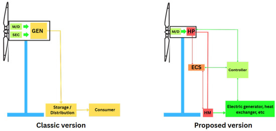
Figure 1.
Classic versus proposed layout of the system.
The hydraulic system under investigation, as detailed in this study, is fundamentally centered around a compact hydraulic pump. This pump features a nominal internal displacement volume of 9 cubic centimeters and is mechanically coupled to an alternating current (AC) electric motor with a rated power output of 2.2 kW. This configuration is further augmented by the integration of a frequency converter, which enables fine-grained control over the rotational speed and acceleration profile of the motor shaft. Consequently, this setup facilitates the reproduction of user-defined dynamic load conditions and temporal power profiles. The ability to apply such customized speed and torque inputs to the hydraulic pump eliminates the requirement for a conventional multiplier gearbox, which would typically be necessary when interfacing with actual wind turbine hardware in an operational setting.
This design flexibility is of particular importance for simulating variable wind conditions, as it permits the emulation of transient aerodynamic loads and fluctuating torque profiles consistent with those experienced in real-world wind energy applications. As a result, the experimental apparatus is capable of reproducing realistic boundary conditions and enables a more accurate and representative evaluation of the system’s thermal, mechanical, and fluid dynamic behavior under operationally relevant scenarios.
The system functions by converting mechanical energy from the electric motor into hydraulic energy via the pump, thereby generating pressurized flow. This pressurized hydraulic fluid is then routed through a series of adjustable and actively controlled flow restriction elements. These components are strategically positioned to introduce hydraulic resistance, which results in internal energy losses, primarily in the form of heat, due to viscous friction within the working fluid—typically a mineral oil. The heat generated by these frictional losses is subsequently extracted and transferred to downstream subsystems, where it may be harnessed for secondary applications such as space heating, fluid preheating, or thermal energy storage. In addition, due to the precise speed control allowed by the frequency converter, almost any speed and acceleration profile can be implemented, thus allowing realistic speed profiles to be tested.
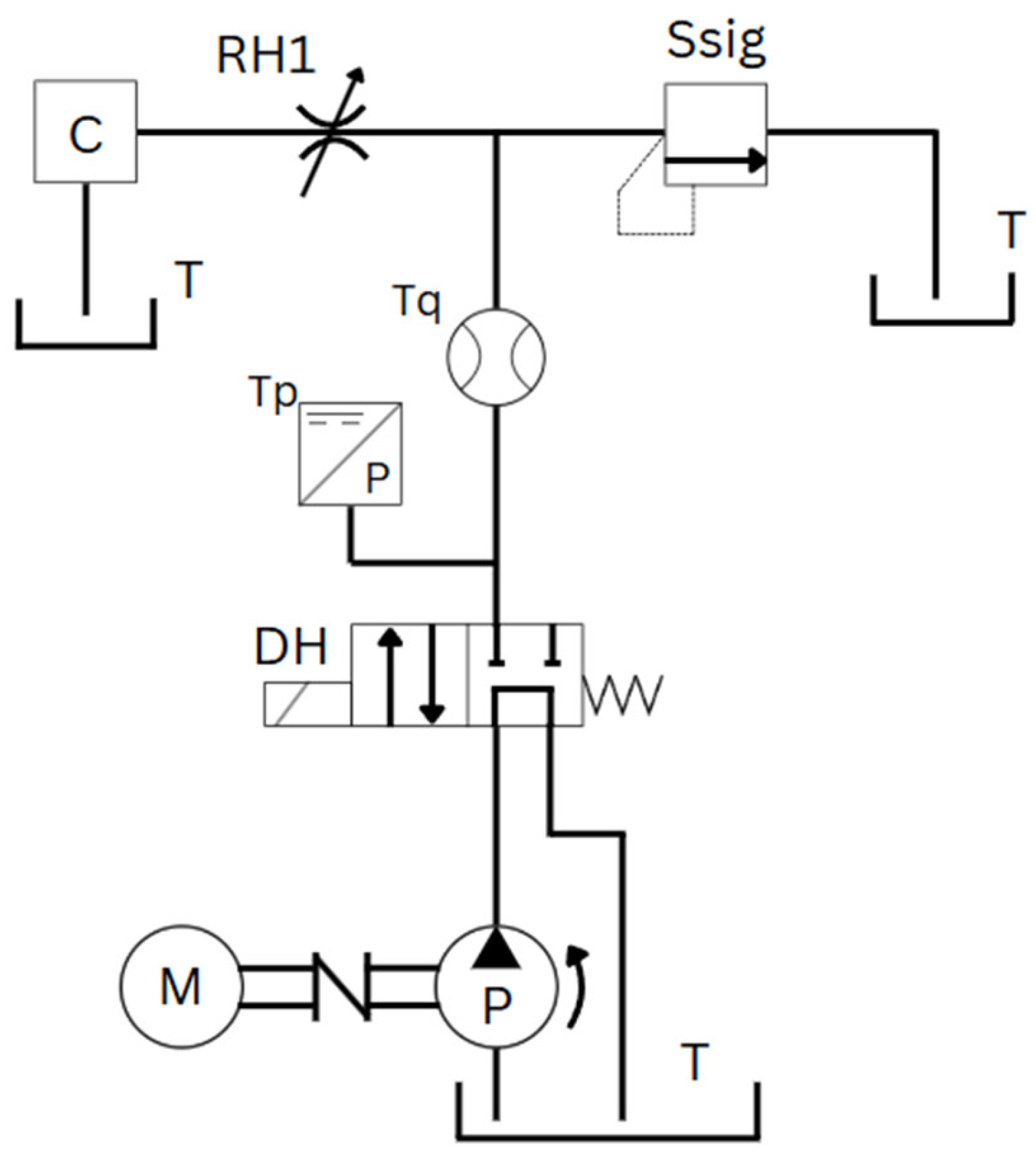
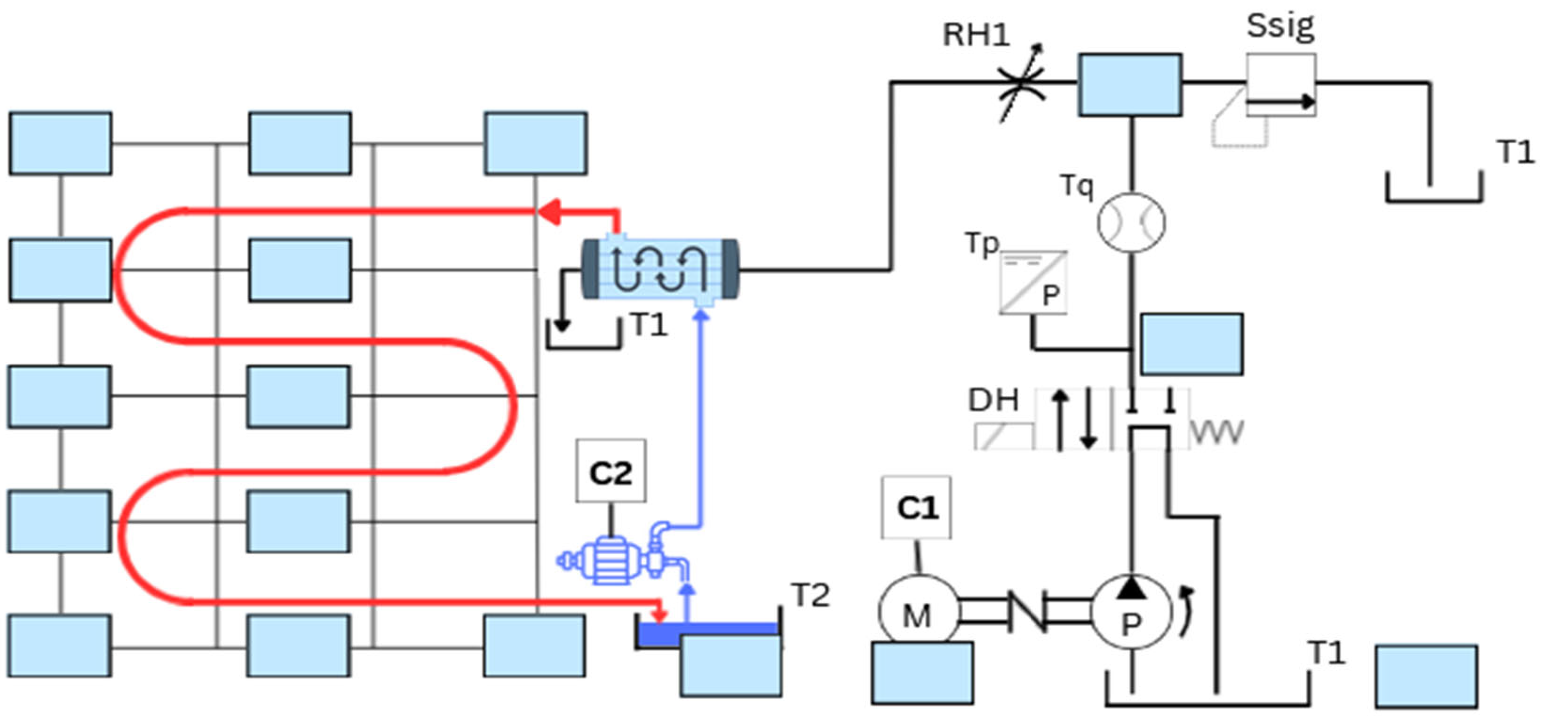
To achieve this, a simplified yet functionally representative hydraulic circuit was conceptualized, constructed, and implemented, as illustrated schematically in Figure 2. The core components of the circuit include the AC motor, designated as M, which delivers mechanical drive to the hydraulic pump labeled P. The pump draws hydraulic fluid from a reservoir or tank, denoted as T. The pressurized fluid is directed either back into the reservoir or toward the system’s load circuit, depending on the operational state of a directional control valve, identified as DH. When DH is de-energized, fluid is bypassed to the tank. When energized, fluid flows into the main hydraulic path.
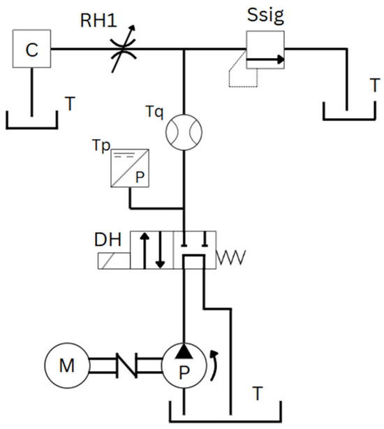
Figure 2.
Hydraulic layout of the system.
Downstream of the DH valve, the system is instrumented with a pressure transducer (Tp) and a flow rate sensor (Tq), which continuously monitor the real-time hydraulic parameters. These measurements are crucial for characterizing the performance of the system and validating simulation models. Additionally, a safety relief valve, labeled Ssig, is incorporated into the circuit to provide overpressure protection. This valve is factory-calibrated to open at a pressure slightly above the system’s nominal operating range, thereby mitigating the risk of structural damage or component failure due to hydraulic overloading.
Thermal energy generation within the circuit is achieved through the use of one or more precision throttle valves, consolidated into a single representative component labeled RH in Figure 2. These valves impose controlled restrictions on the fluid flow, thus generating internal turbulence and viscous dissipation, which are the primary sources of heat generation within the working medium. The heated hydraulic fluid is subsequently delivered to a thermal load or consumer component, designated as C, which absorbs the thermal energy before returning the now-cooled fluid to the system’s reservoir. This closed-loop configuration allows for continuous fluid recirculation and stable thermal operation over extended periods of testing.
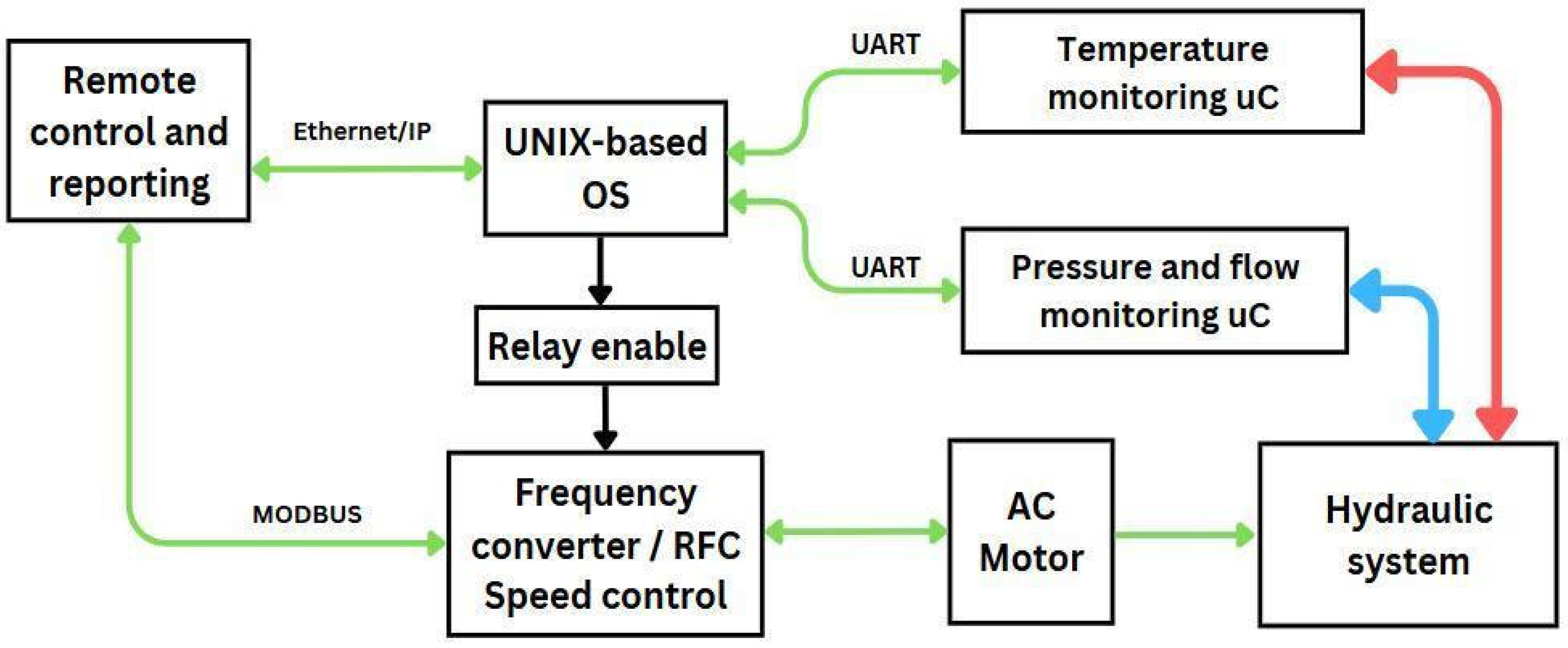
Motor control is achieved using a Nidec frequency converter, which operates via Modbus communication and utilizes Rotor Flux Control-Asynchronous (RFC-A) for precise speed regulation. Fluid pressure and flow are measured immediately downstream of the directional control (way) valve. Temperature is monitored at multiple points within the hydraulic circuit, including the tank, the directional valve, the pump, and the throttle valve. Due to the variety of sensor signal types—analog voltage for temperature, pulse counting for flow, and analog current for pressure—multiple microcontrollers are employed to acquire data from the sensors. These microcontrollers transmit the collected data to a central single-board computer (SBC) for processing.
A redundant control mechanism is implemented by routing the enable signal for the frequency converter through an independent Ethernet-based communication channel managed at the SBC level. This allows for an automatic shutdown of the pump if communication via Modbus to the remote user is lost or if critical system parameters (flow, temperature, pressure) exceed predefined thresholds. These were set at 70 °C for the hydraulic oil, 55 bar pressure, as well as 15 L per minute. The general schematic of the system control is presented in Figure 3. Green arrows represent data signals, while red and blue arrows represent pressure and flow information. Arrow directions show if communication is either unidirectional or bidirectional.

Figure 3.
Control layout.
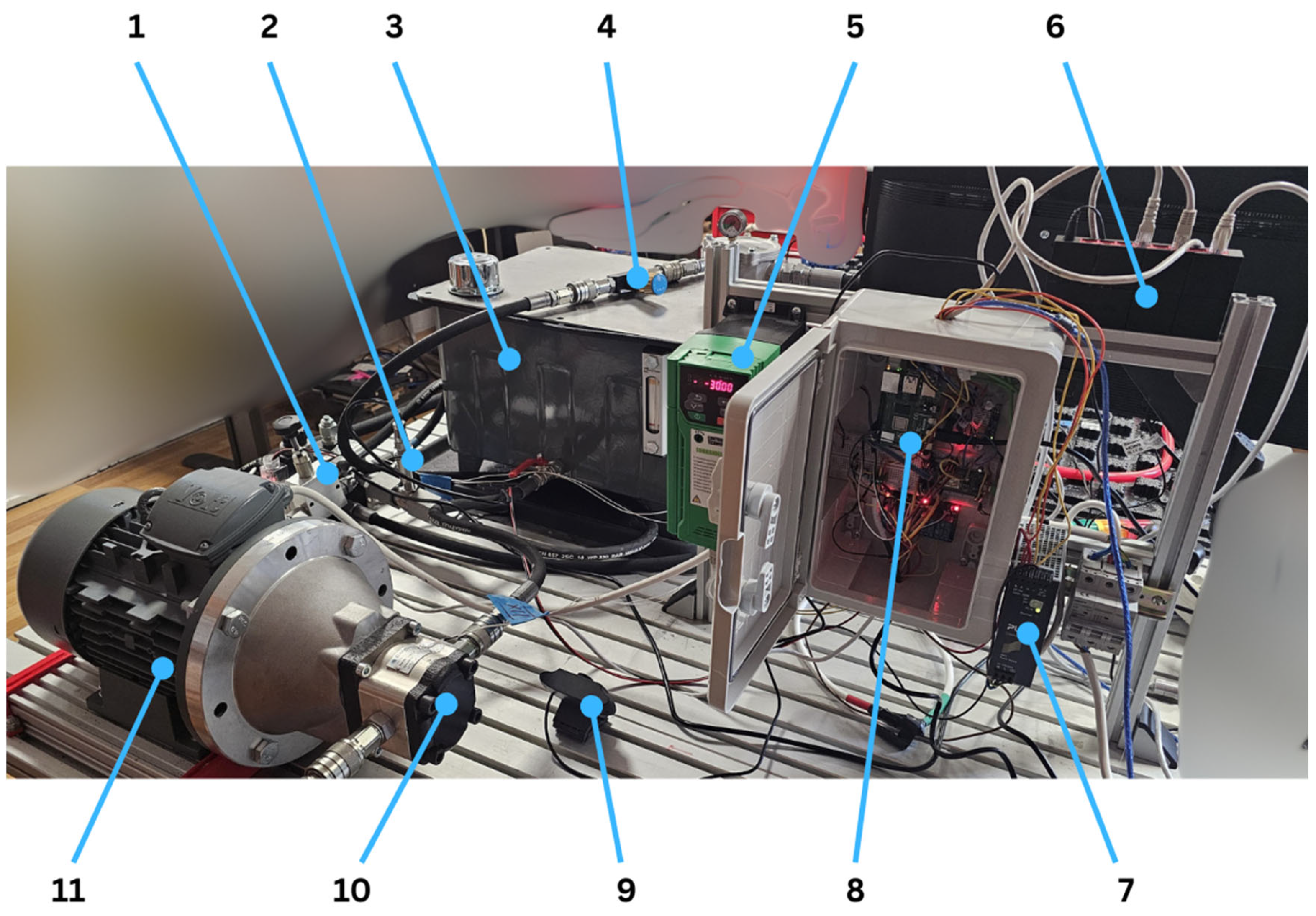
Following the initial system dimensioning and design phase, the physical assembly of the components was carried out. The completed assembly is depicted in Figure 4, which provides a comprehensive overview of the entire system configuration. The labeled components include the directional control valve and pressure sensor (1), the flow sensor (2), the tank (3), and the throttle valve (4). The motor (11) and the pump (10) are regulated by a frequency controller (5) and the control circuit (8), both of which are powered by an AC-to-DC power supply (7). Additionally, a webcam (9) is integrated into the system to enable remote monitoring. Where needed, fused deposition modeling was used to create supports for the equipment used, using settings as specified in [33].
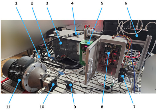
Figure 4.
Physical layout of the system.
The control architecture of the test system was developed using a combination of the Python and C++ programming languages. This dual-language approach was selected to balance ease of development with performance efficiency, particularly in handling real-time data acquisition and control tasks. In addition, a custom-designed graphical user interface (GUI), implemented entirely in Python 3.13.4, was created to provide intuitive interaction with system parameters and real-time monitoring capabilities.
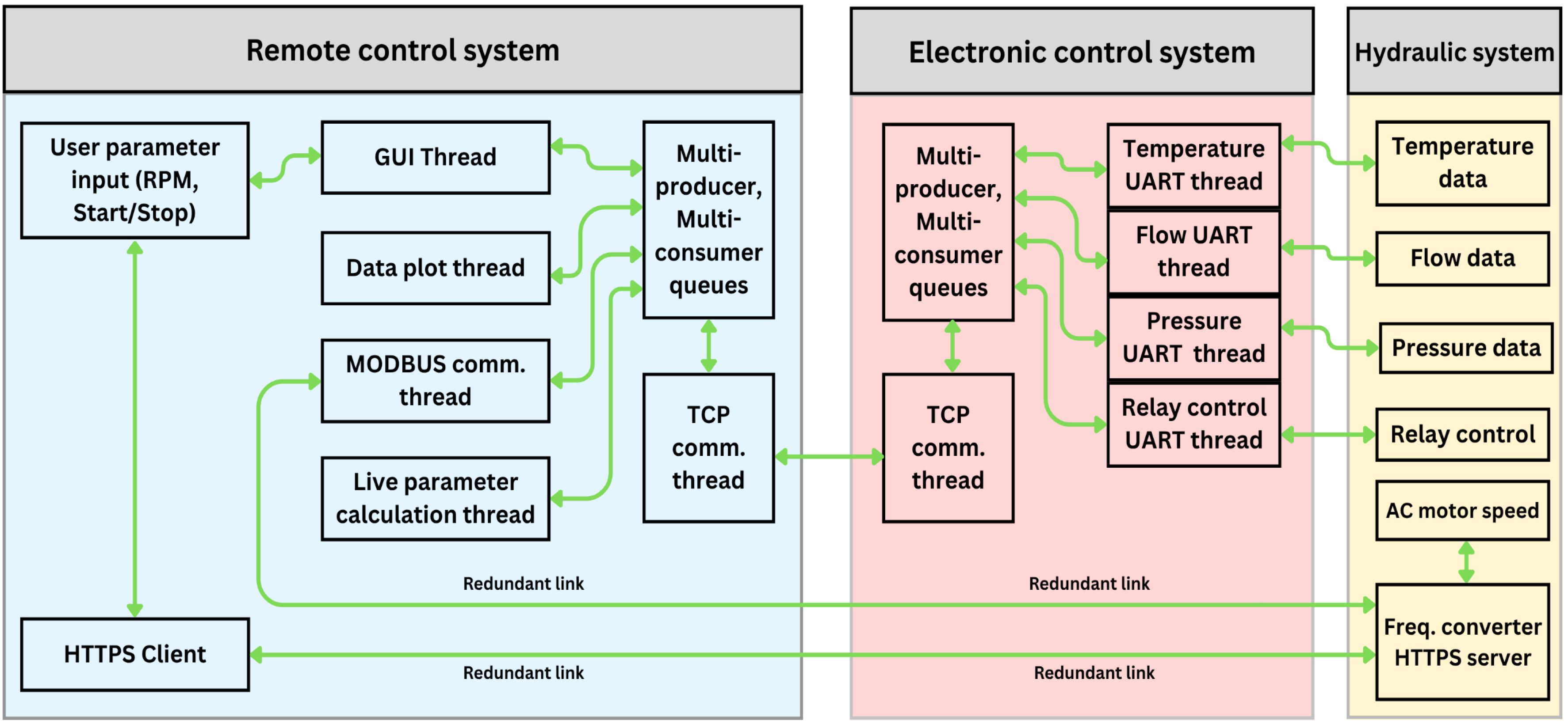
Due to the inherent complexity and concurrency requirements of the test stand—particularly with regard to synchronizing sensor input, motor control, and data logging operations—a multi-threaded programming model was adopted. This approach enabled parallel execution of critical tasks, ensuring responsive system behavior and stable performance under varying operational loads. The overall software structure and thread management strategy are illustrated schematically in Figure 5.
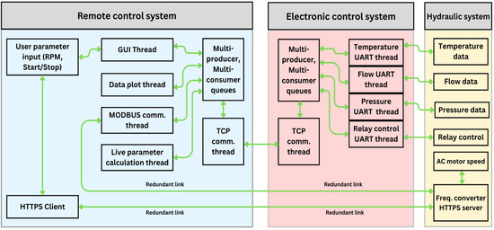
Figure 5.
Overview of software connections.
Special attention was given to ensuring that control of the system is redundant, as it is critical for ensuring operational reliability, safety, and system integrity, particularly in mission-critical applications. By incorporating parallel control pathways and backup components, redundancy mitigates the risk of failure due to single-point malfunctions, hardware degradation, or unexpected environmental disturbances. It enables continuous functionality during component faults, thus preventing catastrophic system collapse.
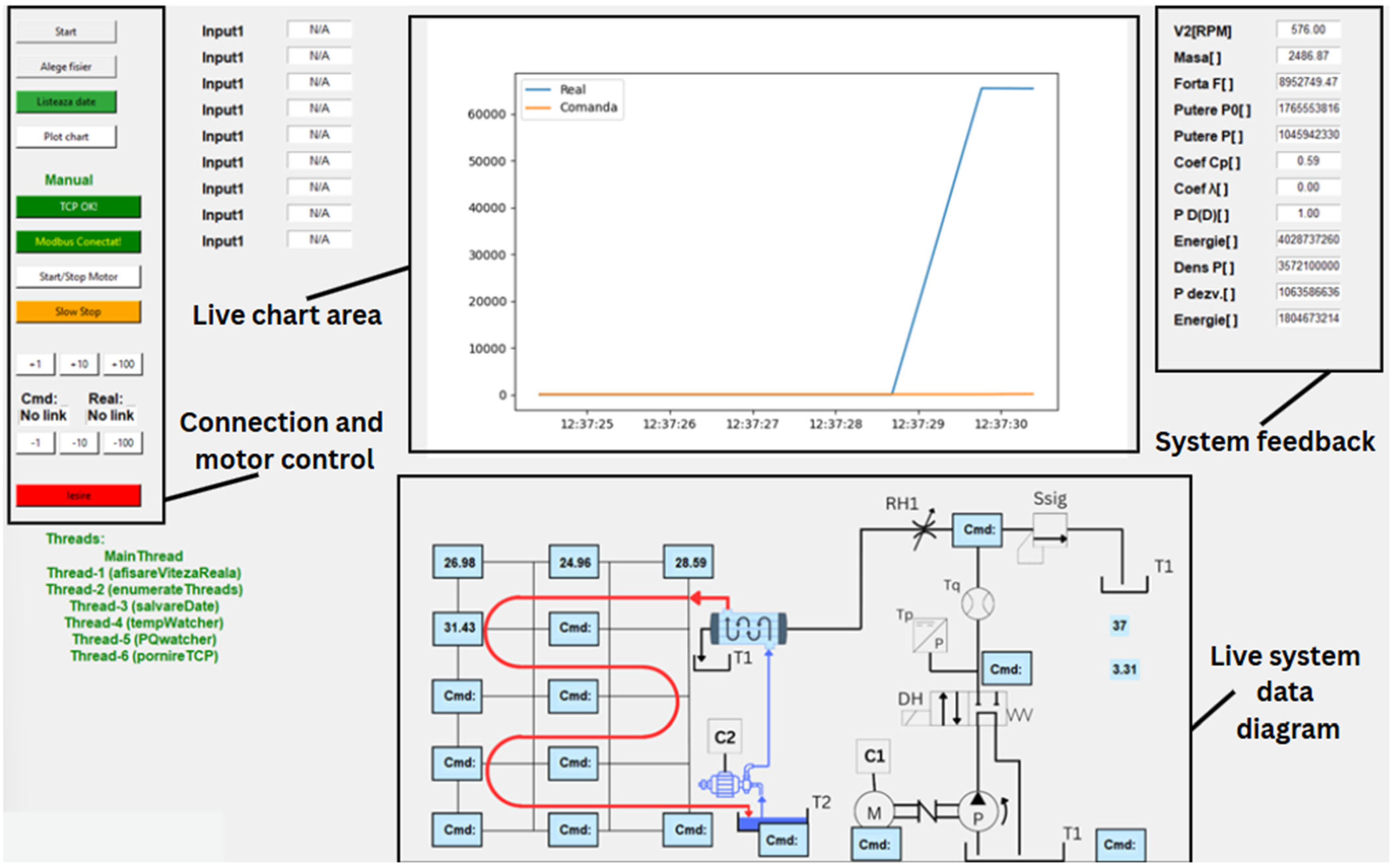
The system is also equipped with a dedicated dashboard interface, specifically developed to facilitate comprehensive control and real-time monitoring of the test stand. This dashboard serves as the central point of interaction for the operator, offering a range of functional controls and live feedback mechanisms essential for precise system operation.
Key features of the dashboard include adjustable controls for setting motor speed, as well as interfaces for establishing and managing communication protocols such as TCP/IP and Modbus. In addition to direct control elements, the interface provides both live and calculated data outputs, enabling continuous observation of system performance.
A designated charting area is integrated within the dashboard (Figure 6), allowing for real-time graphical representation of key parameters over the course of testing. Moreover, a schematic diagram of the control system is embedded in the interface, supplemented by critical operational data such as current temperature readings, system pressure, and oil flow rates. This integrated design ensures that all relevant information is readily accessible, promoting efficient operation and rapid response to any deviations during testing.
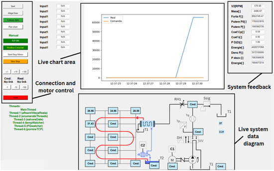
Figure 6.
Dashboard for the designed application.
Since the system operates within a networked environment, significant attention must be dedicated to addressing cybersecurity concerns, including data integrity, unauthorized access prevention, and system resilience against cyber threats. Nevertheless, under the specific conditions of the present study, which was conducted in a controlled laboratory testing environment, cybersecurity was not prioritized. Consequently, minimal-to-no formal security measures were implemented during this phase of development. However, recognizing the critical importance of secure operation in broader, real-world applications, further steps will be undertaken. Future work will involve the integration of comprehensive cybersecurity protocols to ensure safe, reliable usability within larger, interconnected network infrastructures.
3. Startup Parameters and Testing
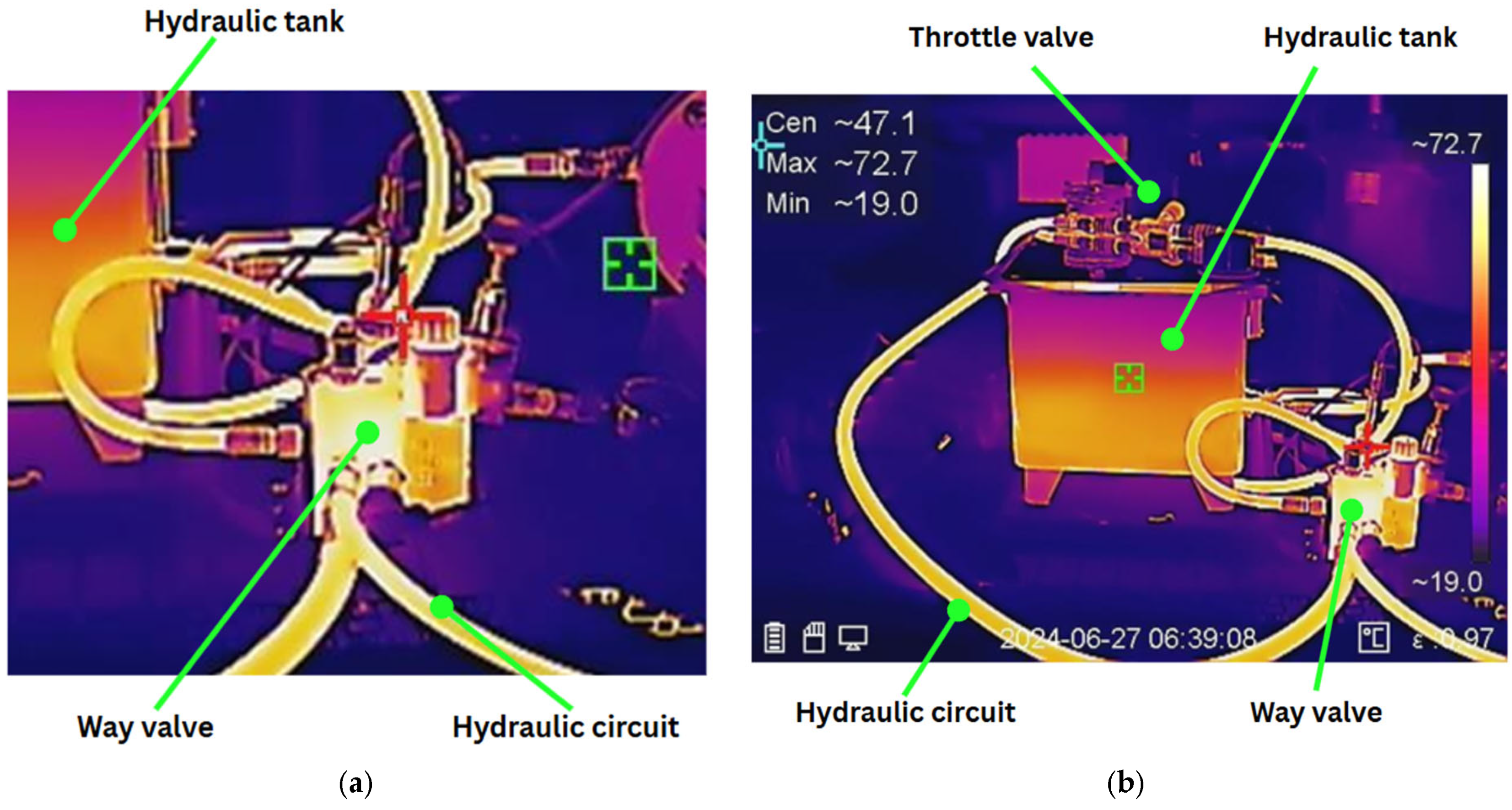
After initial functionality tests of the installation, hydraulic oil was added, and a pressure of 10 bar was generated in the system by using the throttle valve. With the aid of a thermal camera, FLIR E54 24° produced by the company Teledyne FLIR LLC in Estonia, city of Tallinn, we could already observe a small temperature increase of approximately 10 °C over a period of 30 min. This result can be observed in Figure 7 and Figure 8, as captured using a thermal camera. Belco ISO VG 46 oil was used. The oil was provided by the company branch office, the city of Suceava, Romania. It has a kinematic viscosity of 41.4–50.6 cSt at 40 °C, per ISO 3448. Its viscosity index typically ranges from 95 to 105 for mineral oils and higher (120+) for synthetics, ensuring stable viscosity across temperatures. The flash point is generally above 200 °C, and the pour point ranges from −30 °C to −40 °C. Regarding the sensors used, for pressure, a QDW90A sensor produced by Anhui Qidian Automation Technology Co., Ltd., located in the city of Huaibei, China was used. It is a high-precision stainless steel pressure sensor designed for industrial applications. It offers customizable output signals (4–20 mA, 0–10 V, RS485), measures pressures from −0.1 MPa to 60 MPa, and operates in temperatures from −20 °C to 400 °C. The GTLWGY turbine flow meter produced by Anhui Jujie Automation Technology Co., Ltd., located in the city of Wuhu, China, is a precision instrument used to measure liquid flow rates. It operates by detecting the rotational speed of a turbine within the flow stream. Working parameters include flow ranges from 0.1 to 2000 m3/h, pressure up to 25 MPa, and temperatures from −20 °C to 120 °C.
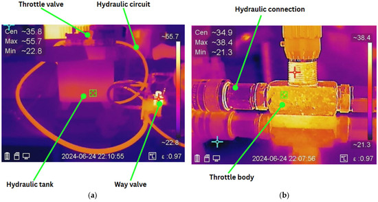
Figure 7.
Thermal camera images of the test stand: (a) initial overview; (b) throttle valve.

Figure 8.
Thermal camera images of the test stand: (a) way valve detail; (b) temperature overview.
Other relevant parameters are 1000 rotations per minute for the pump and a measured flow of approximately 4.7 L/minute for the initial testing of the hydraulic circuit.
Following this stage, a number of tests were performed, at different motor speeds and different pressures set by means of the throttle and safety valve. The attempts performed by the authors are presented in Table 1, with the results represented graphically in Figure 9, Figure 10, Figure 11, Figure 12, Figure 13 and Figure 14. Since all the values in attempt number 1 were constant, except for RPM, there was no need to plot the information. During this attempt, no temperature difference was visible in the system.

Table 1.
Tests performed for the system.
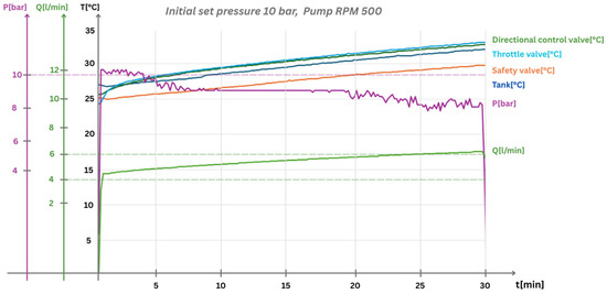
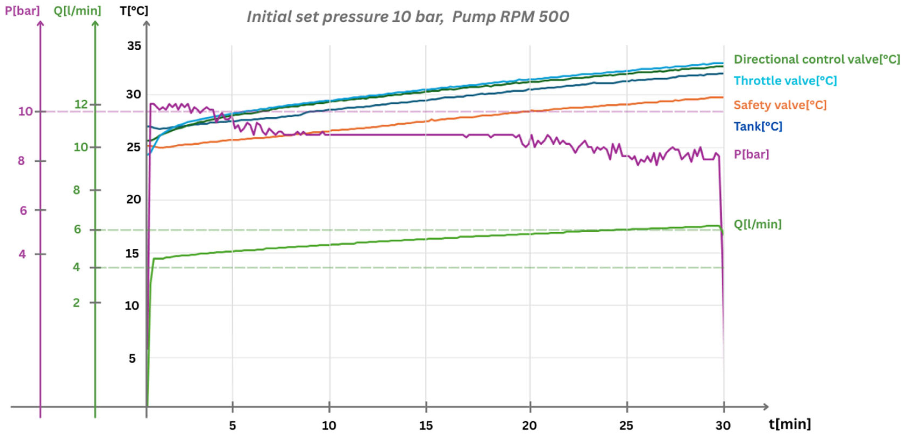
Figure 9.
Results at the initial pressure of 10 bar, motor speed of 500 RPM, and flow of approximately 4 L/min.
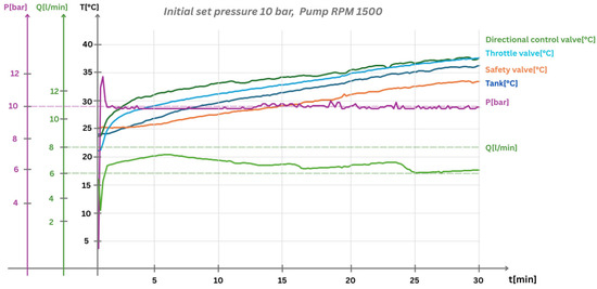
Figure 10.
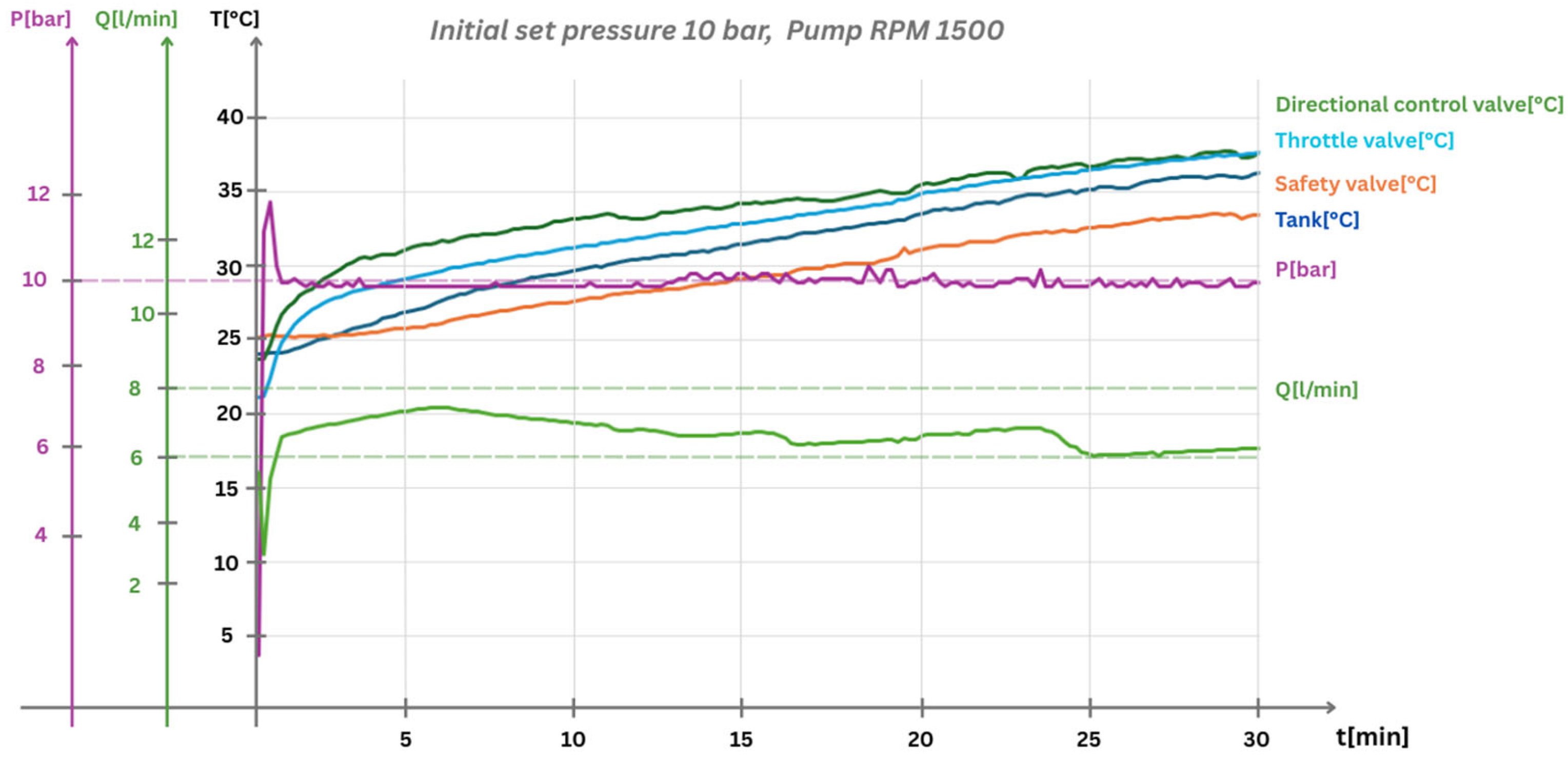
Results for the initial pressure of 10 bar, motor speed of 1500 RPM, and flow of approximately 6 L/min.
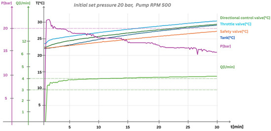
Figure 11.
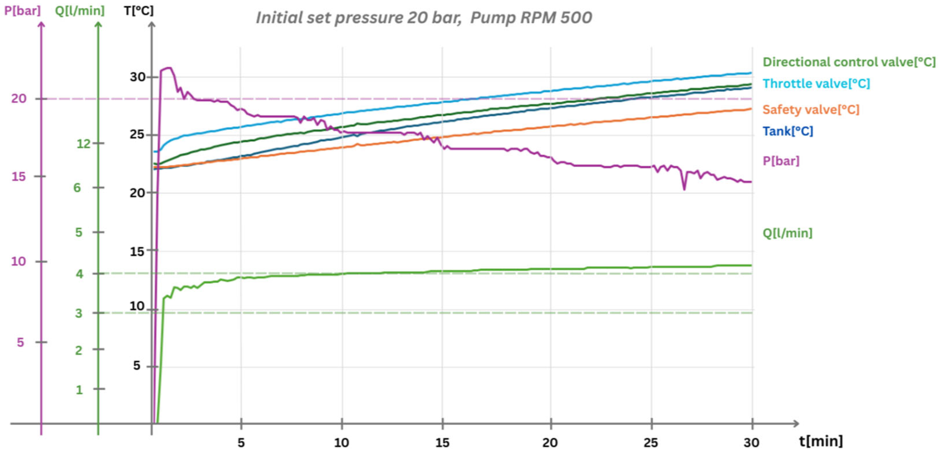
Results for the initial pressure of 20 bar, motor speed of 500 RPM, and flow of approximately 4 L/min.
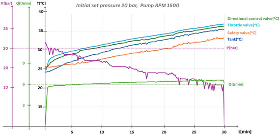
Figure 12.
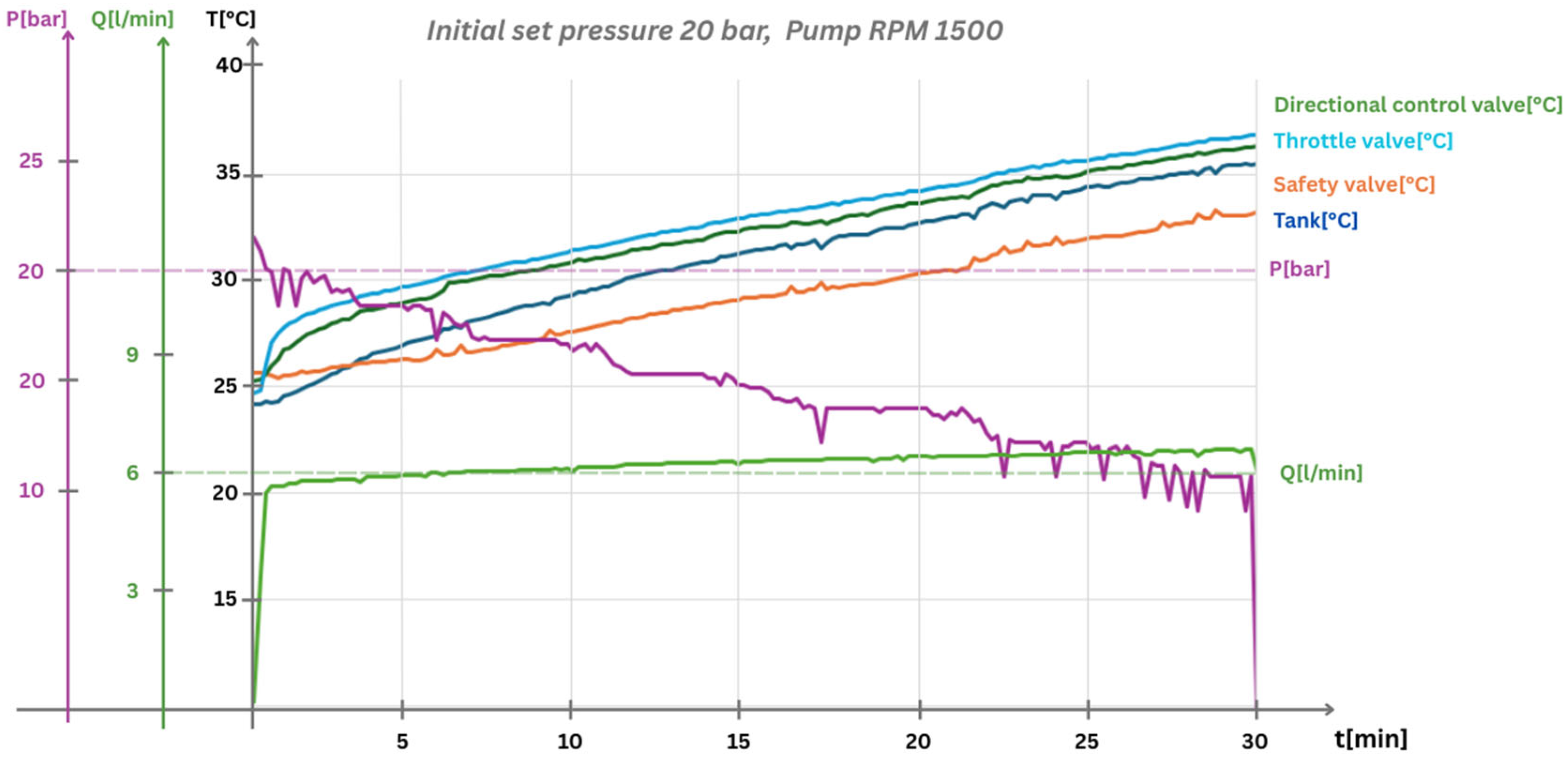
Results for the initial pressure of 20 bar, motor speed of 1500 RPM, and flow of approximately 6 L/min.
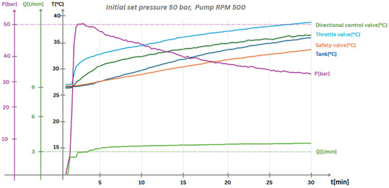
Figure 13.
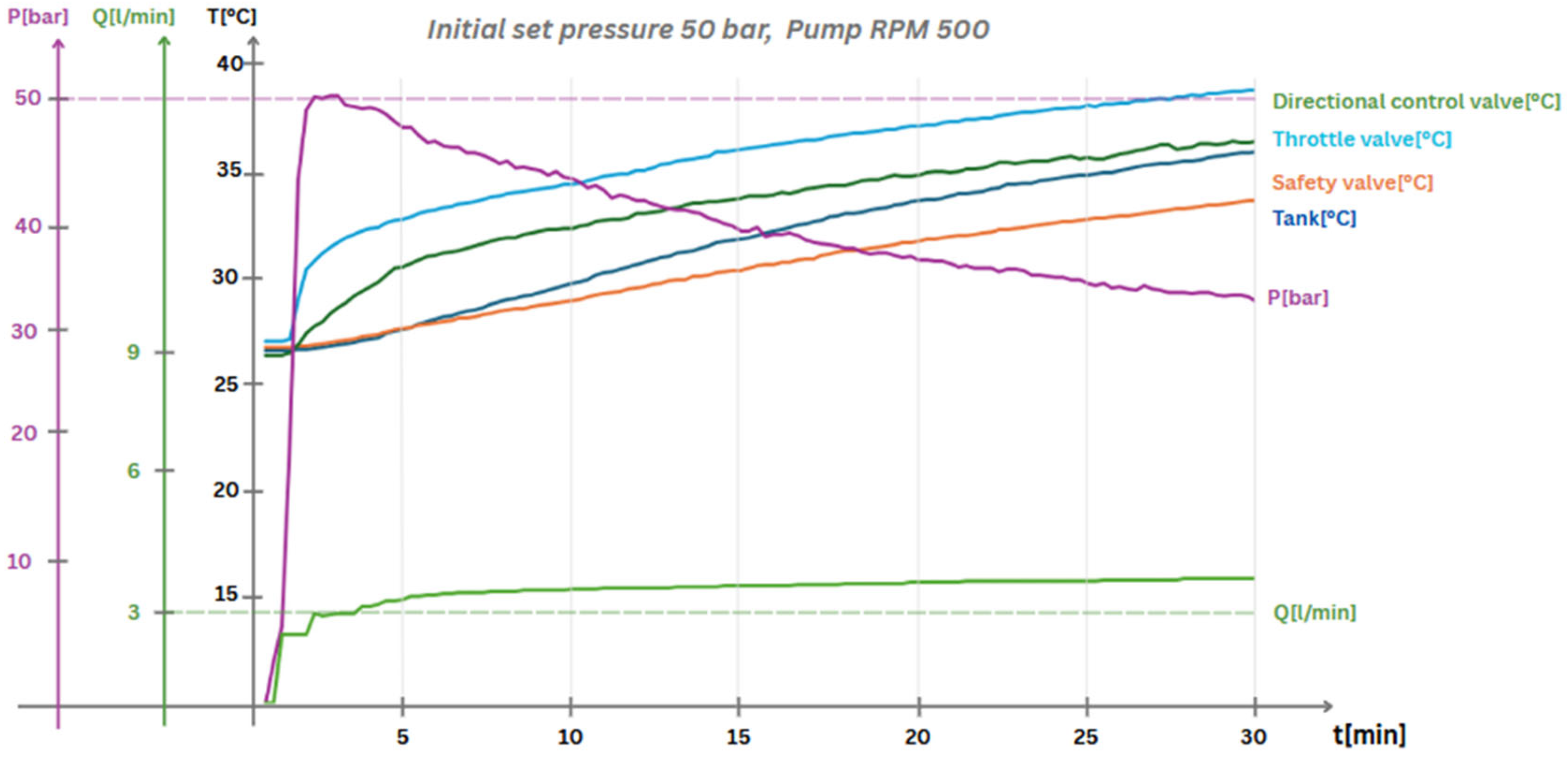
Results for the initial pressure of 50 bar, motor speed of 500 RPM, and flow of approximately 3 L/min.
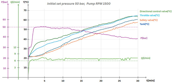
Figure 14.
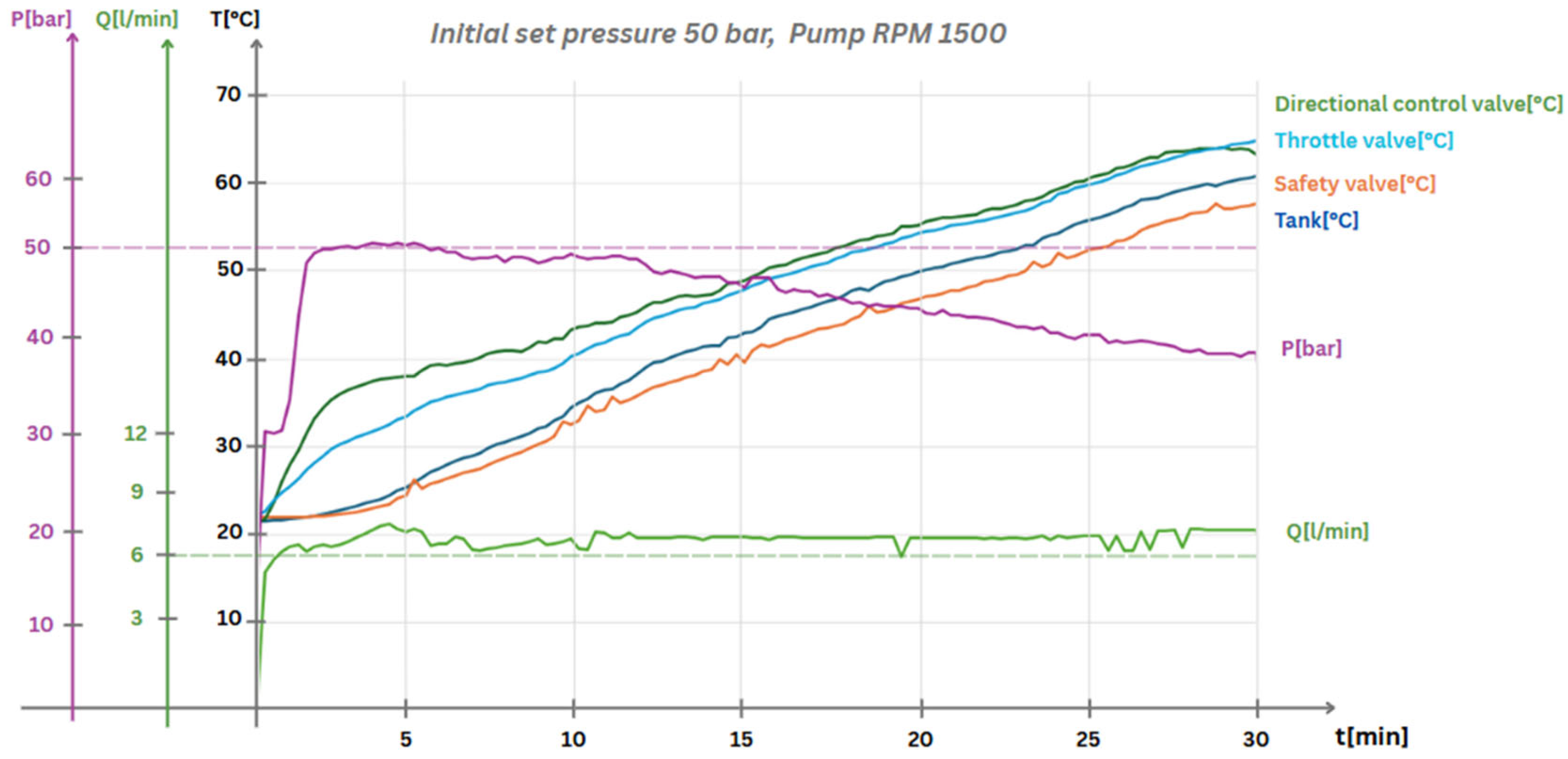
Results for the initial pressure of 50 bar, motor speed of 1500 RPM, and flow of approximately 6 L/min.
Regarding the other attempts, they are shown in Figure 9, Figure 10, Figure 11, Figure 12, Figure 13 and Figure 14 and are discussed in the following part of the paper. All of the attempts were performed over the same period of time—30 min—allowing for the values to be easily compared.
Firstly, an attempt was made at the pump’s lowest speed of 500 rotations per minute, as prescribed by the manufacturer, at an initial set pressure of 10 bar.
As previously stated, the desired system pressure was achieved by sequentially opening the way valve and manually adjusting the flow restriction using the throttle valve, progressively lowering the cross-sectional area available for fluid passage until the target pressure value was reached. During this procedure, a steady and measured oil flow rate of approximately 4.5 L per minute was obtained under stabilized conditions. This process and its associated outcomes are graphically represented and documented in Figure 9.
With respect to the data presented in Figure 9, Figure 10, Figure 11, Figure 12, Figure 13 and Figure 14, it is important to note that an initial overshoot in the measured pressure values occurs consistently. This phenomenon is primarily attributed to the manual nature of the pressure setting at system startup, where fluctuations are unavoidable. Additionally, although the raw data signals acquired from the various pressure and flow sensors within the hydraulic circuit undergo real-time digital filtering to reduce high-frequency disturbances, a certain degree of residual noise remains present. This inherent measurement noise can be observed in the graphical charts.
As depicted in the image, a temperature rise of approximately 8 °C was recorded over the 30 min period. In addition, as expected, due to lower viscosity at higher temperatures, an increase in flow and a decrease in pressure could be observed. Following startup, no modifications were made to the surface area of the throttle valve or to the motor speed.
Following the completion of the initial low-speed trial, the motor speed was increased to 1500 rotations per minute in order to examine the system’s behavior under conditions of higher dynamic input. The results are shown in Figure 10. This adjustment had an immediate and measurable impact on the volumetric flow rate of the hydraulic oil, which increased to approximately 6 L per minute. For this second test, the system pressure was again set to 10 bar, achieved through manual adjustment of the throttle valve to restrict flow and elevate pressure to the desired value.
Over the course of a 30 min operating period, the system exhibited a noticeable thermal response, with the temperature of the working fluid rising by approximately 15 °C. In addition to the thermal effects, a smaller reduction in system pressure was observed relative to earlier tests, accompanied by a modest decrease in the oil flow rate toward the end of the interval. This specific behavior—characterized by elevated temperature, slightly diminished flow, and reduced pressure—was found to occur predominantly under conditions of low pressure (10 bar) in combination with high pump speed (1500 RPM). The observed performance was attributed to intrinsic operational characteristics of the pump, such as internal leakage, efficiency limitations, or temperature-dependent viscosity effects at elevated speeds, which become especially relevant when examining the system’s behavior at different pressure levels with a fixed throttle valve as the only load. At 10 bar, the system operates stably even as oil temperature rises, because the flow demand through the throttle is relatively low and the pump’s internal leakage remains within manageable limits. Although viscosity decreases with rising temperature—slightly increasing the internal slip—the gear pump can still easily maintain the required flow and pressure. This pressure stability is further supported by the fact that flow through a fixed orifice depends on the square root of the pressure drop, allowing the pump to supply sufficient flow to meet demand despite temperature-related changes.
Additional experimental testing procedures were systematically carried out at an intermediate pressure level of 20 bar to further investigate the system’s performance characteristics. Testing was conducted under two distinct operational conditions: first, at the minimum specified pump rotational speed of 500 rotations per minute (RPM), and second, at the maximum operational speed of 1500 RPM. The primary objective of these tests was to thoroughly evaluate and characterize both the thermal response and flow behavior of the hydraulic system while operating at this mid-range pressure setting. Particular attention was given to identifying any nonlinearities, transitional flow phenomena, or thermal instabilities arising under different dynamic load conditions.
The results obtained from both trials (Figure 11 and Figure 12) demonstrated qualitatively similar trends in system behavior. In each case, the thermal response over the 30 min testing period showed only marginal variation when compared to prior results at lower or higher pressures. Notably, a slight increase in oil temperature was recorded, suggesting a modest enhancement in heat generation and retention. However, this improvement was relatively minor and did not represent a significant departure from the general pattern observed across other tested conditions.
Finally, a series of tests was carried out at a significantly higher initial pressure setting of 50 bar, under two distinct operating conditions corresponding to pump speeds of 500 and 1500 rotations per minute. The results are shown in Figure 13 and Figure 14. Under these conditions, a substantially greater thermal gradient was recorded when compared to previous trials. Specifically, at the lower pump speed of 500 RPM, the working fluid exhibited a temperature increase of approximately 15 °C over the standard test duration of 30 min. In contrast, at the higher speed of 1500 RPM, the temperature rise was markedly more pronounced, reaching approximately 43 °C within the same timeframe.
Despite the difference in rotational speed and the resulting thermal behavior, the volumetric flow rate of the hydraulic oil remained relatively consistent with earlier observations. At 500 RPM, the flow rate was measured at approximately 3 L per minute, while at 1500 RPM, it reached ca. 6 L per minute. These results indicate that while flow rates scale predictably with pump speed, the associated thermal effects become significantly more pronounced at elevated pressures and higher operational intensities.
4. Conclusions and Further Work
This paper outlines the design, implementation, and testing of a mechatronic test stand that converts historical wind power data into thermal energy for small-to-medium-sized consumers. It targets applications in densely populated areas, where installing large wind turbines is impractical due to space constraints. The system employs a 2.2 kW AC motor with rotor flux control (RFC) to simulate a wind turbine driving a 6 cm3 hydraulic pump, enabling a compact and lightweight installation. If needed, however, the system can easily be modified to accommodate larger motors and/or pumps. The paper details the system’s schematic, setup, operation, and initial results obtained with the custom-built hydraulic test stand. Future work will focus on analyzing the impact of varying wind patterns and exploring specific use cases for the system.
The paper details the series of steps undertaken to design, construct, and implement a dedicated test stand, specifically intended to simulate wind energy conditions and determine the key parameters required for the effective generation of thermal energy. In this setup, the behavior of wind energy is replicated through the controlled operation of an electric motor, allowing for a systematic investigation into the conversion of mechanical input into usable thermal output under various simulated environmental conditions. The system does not, however, take into account any real-life deployment conditions beyond implementing specific wind speed profiles. Steps are currently being taken to allow the oil to be cooled or heated below or above room temperature, and longer oil pathways are being discussed, as well as including safety precautions into the system.
In the following works, the issue of regulating and ensuring an optimal temperature for the hydraulic fluid will also be addressed. A series of accumulators might be introduced into the hydraulic circuit to store the excess flow generated by higher wind speeds. The fluid will be released from these accumulators when the wind speed drops below the chosen nominal value of 10 m/s. For this system, a lower nominal wind speed than the standard was selected, in accordance with the geographical location from which the wind speed variation data were collected. Generally, in classic and commercial systems, the nominal wind speed is around 15 m/s.
In addition to using accumulators, the replacement of pressure regulation and control equipment with proportional ones will be considered. These allow dynamic adjustment of the system parameters in order to achieve a minimally acceptable oil temperature, ensuring efficient heat transfer to the second working medium. Specifically, in cases where the wind speed falls below 6 m/s, the accumulator will release part of the stored energy. Simultaneously, this energy will be injected into the circuit, and the proportional equipment will adjust the flow rate based on a predefined rule to determine the minimum acceptable temperature.
A second operating scenario would involve recovering hydraulic energy that is otherwise lost when the system’s imposed conditions are exceeded—that is, when the flow exceeds the maximum allowed to maintain a fluid temperature of 60 °C. This energy will be recovered using a three-way flow regulator that redirects the excess fluid to an auxiliary energy generation system. This system consists of a hydraulic motor, an electric generator, and power electronics.
In this scenario, two particular cases might be considered. The first case involves compensating for the thermal energy by using heating elements along the hydraulic line leading to the heat exchanger. This way, the oil is heated to the required temperature, and the hydraulic circuit is not affected by this artificial temperature increase. The power supply for the heating elements will be provided by the auxiliary system. Practically, the electrical energy stored in batteries will be used to power these elements. Thus, the energy from the batteries will be consumed, allowing them to store energy again from the auxiliary system. The second case considered involves using the electrical energy generated from recovering the excess flow to heat a supplementary system installed in the water hydraulic circuit, to heat the water when heat exchange cannot be efficiently achieved.
Following the initial testing phase of the system, the results confirmed the anticipated outcome: the hydraulic oil effectively facilitated the conversion of mechanical energy, supplied by the electric motor, into thermal energy. This conversion process validated the fundamental thermodynamic principles underpinning the system’s design. Subsequent research efforts will focus on the integration of realistic wind speed profiles and corresponding power outputs, emulating the dynamic behavior of the motor shaft under variable operational conditions. Furthermore, the thermal energy generated will be transferred to secondary systems, such as underfloor heating installations or other non-critical energy consumers, which could benefit from this method of energy repurposing. The objective is to enhance the overall efficiency and utility of the system by capturing otherwise wasted mechanical energy and redirecting it toward sustainable and practical applications. A schematic of a possible setup of such a system is shown in Figure 15. Further work will also be undertaken to improve or simulate certain scenarios regarding the type of turbine used, relying on work performed by other scientists [34]. In addition, research is currently being conducted to allow for thermal storage for mid-to-long term use of the energy generated. Furthermore, the system might stand to benefit from using proportional throttle valves, allowing for wind speed compensation for more complex scenarios.
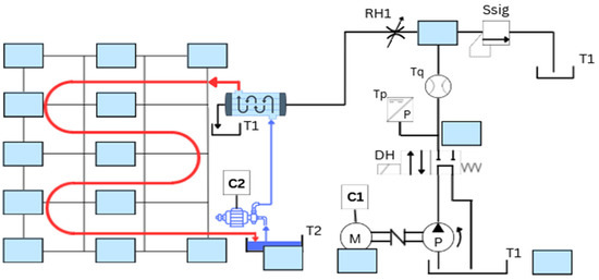
Figure 15.
Example schematic for future applications.
Author Contributions
Conceptualization, V.C. and I.P.; methodology, M.A.; software, V.C.; validation, V.C., I.P. and M.A.; formal analysis, I.P.; investigation, M.A.; resources, V.C.; data curation, I.P.; writing—original draft preparation, V.C.; writing—review and editing, I.P.; visualization, I.P.; supervision, M.A.; project administration, V.C.; funding acquisition, V.C. All authors have read and agreed to the published version of the manuscript.
Funding
This research was funded by a grant from the National Program for Research of the National Association of Technical Universities—GNAC ARUT 2023. Identifier: ARUT 2023—“Controller inteligent IoT pentru sistem eolian de generare a energiei cu transmisie hidrostatica in conceptie mecatronica”, 124/04.12.2023.
Institutional Review Board Statement
Not applicable.
Informed Consent Statement
Not applicable.
Data Availability Statement
The original contributions presented in the study are included in the article.
Acknowledgments
This work was supported by a grant from the National Program for Research of the National Association of Technical Universities—GNAC ARUT 2023.
Conflicts of Interest
The authors declare no conflicts of interest.
References
- Krishnan, A.; Al-Obaidi, A.S.M.; Hao, L.C. A Comprehensive Review of Innovative Wind Turbine Airfoil and Blade Designs: Toward Enhanced Efficiency and Sustainability. Sustain. Energy Technol. Assess. 2023, 60, 103511. [Google Scholar] [CrossRef]
- Sawant, M.; Thakare, S.; Prabhakara Rao, A.; Feijóo-Lorenzo, A.E.; Bokde, N.D. A review on state-of-the-art reviews in wind-turbine- and wind-farm-related topics. Energies 2021, 14, 2041. [Google Scholar] [CrossRef]
- Apata, O.; Oyedokun, D.T.O. An overview of control techniques for wind turbine systems. Sci. Afr. 2020, 10, e00566. [Google Scholar] [CrossRef]
- Loza, B.; Minchala, L.I.; Ochoa-Correa, D.; Martinez, S. Grid-Friendly Integration of Wind Energy: A Review of Power Forecasting and Frequency Control Techniques. Sustainability 2024, 16, 9535. [Google Scholar] [CrossRef]
- Porté-Agel, F.; Bastankhah, M.; Shamsoddin, S. Wind-Turbine and Wind-Farm Flows: A Review. Bound.-Layer Meteorol. 2020, 174, 1–59. [Google Scholar] [CrossRef]
- Moraru, E.; Dontu, G.O.; Cananau, S.; Stanescu, V.A. Approaches and Processing Technologies for Medical Devices: Considerations from Micro-and Macroscale Perspectives. In International Conference on Reliable Systems Engineering; Springer Nature: Cham, Switzerland, 2023; pp. 345–362. [Google Scholar]
- Hise, C.; Obermeyer, B.; Ahlering, M.; Wilkinson, J.; Fargione, J. Site Wind Right: Identifying Low-Impact Wind Development Areas in the Central United States. Land 2022, 11, 462. [Google Scholar] [CrossRef]
- Wang, B.; Zhou, B.; Zhu, D.; Zou, M.; Luo, H. Pre-filtering SCADA data for enhanced machine learning-based multivariate power estimation in wind turbines. J. Mar. Sci. Eng. 2025, 13, 410. [Google Scholar] [CrossRef]
- Bangga, G. Sensitivity of dynamic stall models to dynamic excitation on large flexible wind turbine blades in edgewise vibrations. Energies 2025, 18, 470. [Google Scholar] [CrossRef]
- Chen, W.; Wang, X.; Zhang, F.; Liu, H.; Lin, Y. Review of the application of hydraulic technology in wind turbine. Wind. Energy 2020, 23, 1495–1522. [Google Scholar] [CrossRef]
- Jargalsaikhan, N.; Masrur, H.; Iqbal, A.; Rangarajan, S.S.; Byambaa, S.; Senjyu, T. A Control Algorithm to Increase the Efficient Operation of Wind Energy Conversion Systems under Extreme Wind Conditions. Energy Rep. 2022, 8, 11429–11439. [Google Scholar] [CrossRef]
- Nath, A.P.; Rather, Z.H.; Indian Institute of Technology Bombay. Impact of Randomness of Wind Direction and Turbine Failure on Reliability Performance of Offshore Wind Farm. In Proceedings of the 2nd International Conference on Large-Scale Grid Integration of Renewable Energy in India, New Delhi, India, 5–7 September 2019; Available online: https://regridintegrationindia.org/wp-content/uploads/sites/14/2019/11/RE_India19_081_posterpaper_Nath_Angshu.pdf (accessed on 29 March 2025).
- Toja, F.; Colmenar-Santos, A.; Castro-Gil, M. Urban Wind Energy Exploitation Systems: Behaviour under Multidirectional Flow Conditions—Opportunities and Challenges. Renew. Sustain. Energy Rev. 2013, 24, 364–378. [Google Scholar] [CrossRef]
- Kim, D.; Jeon, T.; Paek, I.; Roynarin, W. Comparison of the wind speed estimation algorithms of wind turbines using a drive train model and extended Kalman filter. Appl. Sci. 2024, 14, 8764. [Google Scholar] [CrossRef]
- Pelin, R.; Barsanescu, P.; Tita, I. Hydraulic systems used for pitch control of wind turbines: A literature overview. IOP Conf. Ser. Mater. Sci. Eng. 2018, 444, 042013. [Google Scholar] [CrossRef]
- Ali, A.E.; Deldar, M.; Anwar, S. Optimal control of hydrostatic drive wind turbines for improved power output in low wind-speed regions. Energies 2021, 14, 5001. [Google Scholar] [CrossRef]
- Sheng, Y.; Escobar-Naranjo, D.; Stelson, K.A. Feasibility of hydrostatic transmission in community wind turbines. Actuators 2023, 12, 426. [Google Scholar] [CrossRef]
- David, J. Electronic Control of Hydraulic Systems; Tampere University of Technology: Tampere, Finland, 2018. [Google Scholar] [CrossRef]
- Doddannavar, R.; Barnard, A.; Mackay, S. Control Components in a Hydraulic System. In Practical Hydraulic Systems: Operation and Troubleshooting for Engineers and Technicians; Elsevier: Amsterdam, The Netherlands, 2005. [Google Scholar] [CrossRef]
- Li, R.; Sun, Q.; Ding, X.; Zhang, Y.; Yuan, W.; Wu, T. Review of Flow-Matching Technology for Hydraulic Systems. Processes 2022, 10, 2482. [Google Scholar] [CrossRef]
- Zhang, Y.; Kong, X.; Hao, L.; Ai, C. Controls of Hydraulic Wind Turbine. MATEC Web Conf. 2016, 40, 08002. [Google Scholar] [CrossRef]
- Liu, Z.; Yang, G.; Wei, L.; Yue, D.; Tao, Y. Research on the Robustness of the Constant Speed Control of Hydraulic Energy Storage Generation. Energies 2018, 11, 1310. [Google Scholar] [CrossRef]
- Ai, C.; Zhang, L.; Gao, W.; Yang, G.; Wu, D.; Chen, L.; Chen, W.; Plummer, A. A review of energy storage technologies in hydraulic wind turbines. Energy Convers. Manag. 2022, 264, 115584. [Google Scholar] [CrossRef]
- Liu, K.; Chen, W.; Chen, G.; Dai, D.; Ai, C.; Zhang, X.; Wang, X. Application and analysis of hydraulic wind power generation technology. Energy Strategy Rev. 2023, 48, 101117. [Google Scholar] [CrossRef]
- Fan, Q.; Zhang, J.; Li, R.; Fan, T. Review of research on hydrostatic transmission systems and control strategies. Processes 2025, 13, 317. [Google Scholar] [CrossRef]
- Yin, X. Design and control strategies for mechanical hydraulic transmission systems. Acad. J. Sci. Technol. 2023, 6, 47–49. [Google Scholar] [CrossRef]
- Lakshmi, V.; Mayurappriyan, P.; Mathew, A.; Mohan, M.; Chandramouleeswaran, G.; Ramasami, S. A Brief Review on Control Strategies for Hydrostatic Transmission-Based Wind Turbines; Elsevier: Amsterdam, The Netherlands, 2024. [Google Scholar] [CrossRef]
- Bai, D.; Wang, B.; Li, Y.; Wang, W. Study on load reduction and vibration control strategies for semi-submersible offshore wind turbines. Sci. Rep. 2025, 15, 1148. [Google Scholar] [CrossRef]
- Tohamy, Y.E.; Giger, U.; Marten, D.; Schulte, H. Multi-Rotor Wind Turbine Control: Strategies for Pitch Replacement and Mechanical Load Mitigation. J. Phys. Conf. Ser. 2024, 2767, 032015. [Google Scholar] [CrossRef]
- Wang, X.; Zhou, J.; Qin, B.; Guo, L. Coordinated power smoothing control strategy of multi-wind turbines and energy storage systems in wind farm based on MADRL. IEEE Trans. Sustain. Energy 2023, 15, 368–380. [Google Scholar] [CrossRef]
- Rodriguez, C.V.; Ríos, A.; Luyo, J.E. CFD Design of Urban Wind Turbines: A Review and Critical Analysis. Int. J. Renew. Energy Res. 2021, 11, 618–637. [Google Scholar] [CrossRef]
- Kassa, B.Y.; Baheta, A.T.; Beyene, A. Current trends and innovations in enhancing the aerodynamic performance of small-scale, horizontal axis wind turbines: A review. ASME Open J. Eng. 2024, 3, 031001. [Google Scholar] [CrossRef]
- Elkodama, A.; Ismaiel, A.; Abdellatif, A.; Shaaban, S.; Yoshida, S.; Rushdi, M.A. Control methods for horizontal axis wind turbines (HAWT): State-of-the-art review. Energies 2023, 16, 6394. [Google Scholar] [CrossRef]
- Dragomiescu, A. Numerical study of a wind turbine with cross-flow runner. UPB Sci. Bull. 2009, 71, 54–64. [Google Scholar]


Disclaimer/Publisher’s Note: The statements, opinions and data contained in all publications are solely those of the individual author(s) and contributor(s) and not of MDPI and/or the editor(s). MDPI and/or the editor(s) disclaim responsibility for any injury to people or property resulting from any ideas, methods, instructions or products referred to in the content. |
© 2025 by the authors. Licensee MDPI, Basel, Switzerland. This article is an open access article distributed under the terms and conditions of the Creative Commons Attribution (CC BY) license (https://creativecommons.org/licenses/by/4.0/).