
Development of a Versatile Strategy for Inkjet-Printed Molecularly Imprinted Polymer Microarrays
1
CNRS Institute of Enzyme and Cell Engineering UMR7025, Université de Technologie de Compiègne, CS60319, 60203 Compiègne, France
2
Laboratoire IMS, Université de Bordeaux, CNRS, Bordeaux INP, UMR 5218, 33607 Pessac, France
*
Author to whom correspondence should be addressed.
Chemosensors 2022, 10(10), 396; https://doi.org/10.3390/chemosensors10100396
Submission received: 26 August 2022
/
Revised: 20 September 2022
/
Accepted: 24 September 2022
/
Published: 28 September 2022
(This article belongs to the Section Analytical Methods, Instrumentation and Miniaturization)
Abstract
:Biochips are composed of arrays of micropatterns enabling the optical detection of target analytes. Inkjet printing, complementary to commercially available micro- and nanospotters, is a contactless and versatile micropatterning method. Surprisingly, the inkjet printing of molecularly imprinted polymers (MIPs), also known as biomimetic synthetic antibodies, has not been demonstrated as yet. In this work, core–shell structures are proposed through the combination of inkjet printing of the core (top-down approach) and controlled radical polymerization (CRP) to decorate the core with a thin film of MIP (bottom-up approach). The resulting biochips show quantitative, specific, and selective detection of antibiotic drug enrofloxacin by means of fluorescence analysis.
1. Introduction
The integration of multiple lab processes on small chip-sized substrates is one of the hot topics in the fields of biology and chemistry, leading to the development of a large variety of lab-on-a-chip devices. The latter have the potential to replace heavy and complex laboratory equipment with miniaturized assays comprising low chip costs, compactness, easy operational set-ups, high speeds, and reduced sample consumption [1,2]. Biochips are simple and well-established examples of lab-on-a-chip devices [3]. Classically, biochips are arrays of biomolecules immobilized on a small glass or silicon substrate [4]. They can be used for drug screening, environmental analysis, and many other chemical or biological applications [5]. For these biochips, molecularly imprinted polymers (MIPs) offer interesting alternatives to the typically used biomolecules and they have been reported in several applications [6,7]. MIPs, in contrast to their natural counterparts, are chemically and physically more stable; they can be chemically tuned, shaped, and processed at micro- and nanoscales, which makes them especially interesting for their integration as receptor elements for lab-on-a-chip applications [8]. For this, various micro- and nanofabrication strategies for the synthesis, patterning, and processing of MIPs have been developed in the past decades. Mechanical methods, while often based on light [9,10], in particular micro-contact printing [11], mechanical spotting [12], and shadow-masking [13], have also been applied.
To fabricate biochips, mechanical deposition and patterning of small liquid volumes are well-established approaches, and commercially available nanospotters routinely deposit small patterns of droplets on a biochip [14]. However, the most popular mechanical spotting device is likely the inkjet printer, which reproduces digital images by precise, contactless depositions of small ink droplets on a substrate [15]. To date, inkjet printers have been widely used by industries as well as private consumers. Surprisingly, the inkjet printing of MIPs has not been demonstrated as yet. In this paper, the feasibility of inkjet-printed MIP microarrays is shown using an innovative strategy, which combines inkjet microprinting with a nanofabrication technique based on controlled radical polymerization (CRP). The key feature here is the use of an iniferter, which enables the grafting of a thin MIP shell on top of the inkjet-printed core polymer by reinitiation and post-polymerization. Here, we chose enrofloxacin (a quinolone antibiotic that is widely prescribed in veterinary medicine) as a target of the bioassays. This drug can, if used in excess, persist in the tissues of animals and, therefore, is a potential risk factor for consumers [16]. Thus analytical methods, such as microbiological detection schemes, are important to analyze and quantify quinolones [17]. Several articles have already demonstrated that MIPs offer alternative approaches to detecting these antibiotics [18,19,20]. In addition, enrofloxacin exhibits intrinsic fluorescence, which enables the evaluation of fabricated MIP patterns by epi-fluorescence microscopy [20].
2. Materials and Methods
2.1. Materials, Chemicals, Devices
All chemicals and solvents were of analytical grade and purchased from Sigma-Aldrich (St. Louis, MO, USA). PVDF Syringe filters with pore sizes of 5 μm were obtained by Whatman (Little Chalfont, United Kingdom). Microscope glass coverslips (15 × 15 mm) by Menzel (Braunschweig, Germany) were used as the substrates. The inkjet printer was a Jetlab 4 by Microfab (Amesbury, MA, USA) equipped with a piezoelectrically actuated droplet generator and a Microfab glass micro-dispenser (aperture 50 μm). Patterned MIP features for the binding evaluation were analyzed by an epi-fluorescence microscope equipped with a 10 × /0.3 objective (Leica DM6000B, Wetzlar, Germany). Pictures of other MIP patterns were taken by a fluorescence microscope equipped with a 2.5 × /0.06 and 10 × /0.06 objective. The thicknesses of single, inkjet-printed polymer drops were evaluated with an optical profilometer (Veeco 9080, San Jose, CA, USA).
2.2. Design of Inkjet-Printed MIP Biochips
All presented polymer features were designed via Microsoft Paint (Microsoft Windows 10) and saved as bitmap files. The three letters “MIP” were written in the font style Calibri.
2.3. Sample and Substrate Preparation
2.3.1. Substrates
All samples were printed on microscopic cover glasses, surface-modified with 3-(trimethoxysilyl)propyl methacrylate. For that, the glass slides were sonicated 15 min in a 2% solution of Hellmanex detergent, acetone, ethanol, and isopropanol, respectively. After drying, the slides were activated by UV ozone for 7 min and placed in a solution of 4 mmol 3-(trimethoxysilyl)propyl methacrylate in 200 mL of ethanol and 6 mL of diluted acetic acid (1:10 glacial acetic acid:water). After ~10 min of reaction time, the samples were thoroughly rinsed with ethanol and isopropanol, and then they were dried. The method was adapted from the product information datasheet by Sigma-Aldrich (St. Louis, MO, USA) [21].
2.3.2. Inkjet Printing of Bulk MIPs
For the printing of bulk MIPs, 1 mmol enrofloxacin, 4 mmol methacrylic acid (MAA), and 4 mmol 2-hydroxyethyl methacrylate (HEMA) were dissolved in 8.5 mL of anhydrous butyronitrile. Next, 20 mmol of ethylene glycol dimethacrylate (EGDMA) and 0.24 mmol of Irgacure 819 polymerization initiator were added and the whole mixture was purged with nitrogen for 5 min. Right before fabrication, the mixture was transferred through a syringe filter to the sample cuvette of the inkjet printer. Samples were printed in the drop-on-demand mode by regulating the backpressure between 8 and 12 mmHg and with a drop spacing of 211 μm for 71-pixel images. In the final step, the inkjet-printed features were transferred into a nitrogen-pressured glove box and polymerized for 30 min using a 365 nm UV light source.
2.3.3. Inkjet Printing of Core–Shell MIPs
The core–shell MIPs were fabricated in two steps. For the printing process of the core polymer dots, 10 mmol of trimethylolpropane trimethacrylate (TRIM) and 1 mmol of benzyl-N,N-diethyldithiocarbamate (BDC) photoinitiator were dissolved in 2 mL of o-xylene and filtered through a syringe filter prior to use. Samples were printed as described before but with varying drop spacings (211 μm for the 71-pixel image; 180 μm for the 101-pixel image; 148 μm for the 101-pixel image; 130 μm for the 101-pixel image). After fabrication, samples were transferred to a nitrogen-pressured glovebox and polymerized using a 312 nm UV light source (30 min). In the second step, a MIP shell was grafted on top of the inkjet-printed core structure. For that, samples were transferred into a petri dish and covered with a MIP pre-cursor solution consisting of enrofloxacin (1.5 mmol), MAA (12 mmol), HEMA (12 mmol), EGDMA (60 mmol), and anhydrous acetonitrile (20 mL). The Petri dishes were placed under a 312 nm UV light source for polymerization (6 h).
2.4. Evaluation of Fabricated Devices
Both bulk MIP structures and core–shell structures were analyzed by fluorescence microscopy (Leica DM6000B, Wetzlar, Germany). Brightfield and fluorescence images were taken using a 2.5 × /NA: 0.06 and a 10 × /NA: 0.3 objective. Intrinsic fluorescence of enrofloxacin was used to evaluate the rebinding of the analyte into the MIP. The excitation/emission wavelengths were set at 280/440 nm for fluorescence measurements. The brightness and contrast were adjusted with the software ImageJ if necessary. The thicknesses of the single inkjet-printed polymer dots were evaluated with an optical profilometer (Veeco 9080).
2.5. Binding Tests of the Core–Shell Structures
The binding properties of the core-shell fabricated MIP assays were evaluated by equilibrium binding experiments. Before the template extraction, a fluorescence image of the structure was taken using a 10 × objective. The obtained fluorescence value was set to 1 as a reference point. After each extraction or binding step, fluorescence images were taken. For the template extraction, the array was incubated 3 times for 2 h in acetic acid/ethanol (1:10) and rinsed thoroughly with acetonitrile. For the binding studies, the microarrays were exposed to 5, 10, and 50 μM of enrofloxacin in acetonitrile for at least 2 h. Extraction and incubation times may be optimized for a given MIP composition and layer thickness. To assess the specificity of the MIP, the same structure was exposed to 50 μM of enrofloxacin, and after extraction, to 50 μM of flumequine. The fluorescence intensity was analyzed with the software ImageJ. The region of interest was selected and the values “area” and “integrated density” were measured. Next, the non-fluorescent background was analyzed by measuring the “mean gray value”. The corrected fluorescence was calculated by [22]:
𝐹𝑙𝑢𝑜𝑟𝑒𝑠𝑐𝑒𝑛𝑐𝑒𝐶𝑜𝑟𝑟;𝑁𝑜𝑟𝑚 = 𝑖𝑛𝑡𝑒𝑔𝑟𝑎𝑡𝑒𝑑 𝐷𝑒𝑛𝑠𝑖𝑡𝑦 − (𝑎𝑟𝑒𝑎 × 𝑚𝑒𝑎𝑛 𝑔𝑟𝑎𝑦 𝑣𝑎𝑙𝑢𝑒)
3. Results
For the initial tests, non-imprinted polymer features based on TRIM were inkjet-printed printed on a 15 × 15 mm2 microscope cover glass. For that, two regions were defined on the glass. For the evaluation of binding properties and the characterization of the droplet size, a pattern of single droplets was printed on one side of the substrate. To prove the feasibility of printing complex structures on a micron scale, the three letters “MIP” were printed on the other half of the microarray chip. A schematic illustration of the microarray chip and two microscope images of the two areas are presented in Figure 1. Some of the major advantages of inkjet printing are that it is based on direct writing with no additional masks (used for standard photolithography) or stamps (needed for soft-lithography). Thus, different designs could be simply generated and modified with Microsoft Paint software.
For many microfabrication methods of MIPs (and polymers in general), the viscosity of the formulation has to be adjusted, and formulations with higher densities have to be used to create well-defined polymer patterns. The viscosity adjustment is also for inkjet printing one important parameter. If the viscosity is too low, printed droplets will spread more easily, whereas inks that are too viscous are difficult to process. Typical ink formulations for inkjet applications have a viscosity of 2 cP [23], although for special applications, printer systems have been reported that can handle highly viscous inks between 20 and 100,000 cP [24]. The viscosity of the samples in our experiments was adjusted to 5 cP by adding 50 wt% o-xylene to the TRIM monomer. Separated and homogeneous polymer droplets were printable with formulated pre-polymer mixtures and the viscosity was low enough to allow the channel of the inkjet nozzle to be refilled in 100 μs (Figure 1). In addition viscosity, the surface tension of the substrate and the hydrophobicity of the ink are crucial parameters for inkjet-printed features. Therefore, extensive cleaning of the substrate was essential in order to obtain homogeneously-printed patterns. The hydrophobic solvent o-xylene was chosen for the viscosity adjustment of TRIM and enabled the printing of uniform droplets that did not spread on the surface of the substrate. Furthermore, the solvent o-xylene was less volatile than the more commonly used toluene and, thus, did not evaporate too quickly. High evaporation rates of the solvent could result in a volume change of the printed droplets and heterogeneously-printed patterns, or even block the nozzle of the printer before printing. This is especially important for small volumes, such as inkjet-printed droplets (volume in the picolitre range), which are more affected by evaporation, due to their larger surface-to-volume ratio. Concretely, feature sizes of 65 μm in diameter and 6.7 μm in thickness were determined with an optical profilometer (Figure 2d). The drop spacing was the main value that was varied in order to obtain homogeneously-patterned structures. Figure 2a–c present three polymer patterns with drop spacings of 211 μm (image size of 71 pixels); 200 μm (image size of 101 pixels) and 180 μm (image size of 101 pixels), respectively. It can be seen that by adjusting the drop spacing, individually-printed droplets merged, and a homogeneous pattern could be achieved (Figure 2c). Figure 2b shows a half-merged structure. This might be the result of heterogeneous surface tension and mechanical movements of the drops. According to the requirements of the application, the print settings could be adjusted to print separated small droplets or bigger feature sizes. For most inkjet applications, the drop spacing is set to a value where the inks on the substrate merge.
We then moved to the fabrication of MIP structures. Two concepts for the fabrication of inkjet-printed microarrays based on MIPs were investigated. Figure 3 illustrates the two approaches that were employed for the development of MIP arrays targeting the drug enrofloxacin. In the first approach (A), a MIP precursor was directly printed on the substrate and polymerized with a 365 nm UV light source. Mechanical deposition for the direct microfabrication of a microarray based on MIPs was already proposed by writing MIP microstructures with a nanofountain pen [12] or with a silicon cantilever matrix [25]. However, the direct writing of MIPs by inkjet printing has never been demonstrated. In the second approach (B), a core polymer pattern was printed from the trifunctional cross-linking monomer TRIM in the first step. The key feature of this approach was the use of the iniferter-type polymerization initiator BDC. This CRP initiator creates under UV irradiation one radical that initiates polymerization and one “stable” radical, capable of terminating the growing polymer chain by recombination [26]. As a consequence, these molecules exhibit ‘living’ characters of the polymerized TRIM core, and a second polymer layer, the MIP shell, can be grafted on top through post-polymerization after reinitiation. The combination of microfabrication methods and iniferter-based polymerization was already proposed as part of a more chemical approach, where the iniferter was covalently bound to a silicon bead, suggesting that this approach could be transferred to microfabrication techniques, such as photolithography. The advantage of this technique is its versatility. The polymer core can be fabricated from different materials of different viscosities and, thus, can be potentially adapted by many other microfabrication techniques, such as photolithography or soft-lithography [27]. However, once optimized for a given application, it does not need re-adaption with respect to a specific MIP. Indeed, this technique allows for the integration of many MIPs already described in the literature without changing the established inkjet printing formulations and conditions.
For the direct approach, the MIP targeting enrofloxacin was printed directly on the substrate. Butyronitrile was used as a porogenic solvent of the MIP precursor solution. This solvent was used by Barrios and co-workers to fabricate a MIP diffraction grating targeting enrofloxacin [28]. Butyronitrile is less volatile than the commonly used acetonitrile and should be less prone to evaporation. In Figure 4a,b, the “MIP” pattern and droplets of printed and polymerized MIP solutions are presented. Since butyronitrile is in contrast to xylene a polar solvent, printed features spread on the surface of the substrate, leading to a reduced resolution of the printed pattern. The droplets spread in non-uniform directions and had feature sizes between 500 μm and 800 μm. Although the less volatile solvent butyronitrile was used for fabrication, the solvent evaporated too quickly from the very thin printed layer and as a consequence the template molecule enrofloxacin precipitated in thin needles within the polymer structures. One possibility of overcoming these issues was replacing the solvent butyronitrile. The hydrophobic solvent 1-methylnaphthalene was able to dissolve enrofloxacin, and structures with smaller feature sizes and uniform spread could be fabricated (Figure 4c). Moreover, in some pattern drops, the template precipitated, and some droplets polymerized as a homogenous polymer with the template dissolved in the polymer matrix. However, changing the MIP formulation from a polar solvent, such as acetonitrile or butyronitrile to a nonpolar solvent, can interfere with the binding properties. Furthermore, it turned out that the evaluation of the binding was challenging due to the big fluorescence background of the bulk polymer. Thus, we changed our strategy, and instead of a bulk polymer pattern, we decided to rely on a core–shell structure.
The sizes and heights of printed iniferter–polymer cores are shown in Figure 2. After polymerizing the core polymer, a thin MIP layer was polymerized by reinitiation with the iniferter BDC. Due to the dimensions (50 to 60 μm) and the spherical shape of the core, it was difficult to analyze the thickness of the shell, which was estimated to be in the nanometer range. Sellergren and co-workers reported shell thicknesses of around 15 nm [27], whereas Marchyk and co-workers found shell thicknesses, depending on the fabrication conditions, between 5 and 116 nm [29]. Since similar conditions were used to graft the MIP shell, it can be assumed that, in our case, the shell thickness was between 10 and 100 nm. The success of the MIP shell grafting could be verified by fluorescence microscopy due to the template enrofloxacin in the MIP. Indeed, a bright fluorescence was observed after the grafting step (Figure 5c). The living character of the core-bound BDC was demonstrated by a control experiment using the conventional FRP initiator Irgacure 819 instead of the iniferter, resulting in no significant increase in fluorescence.
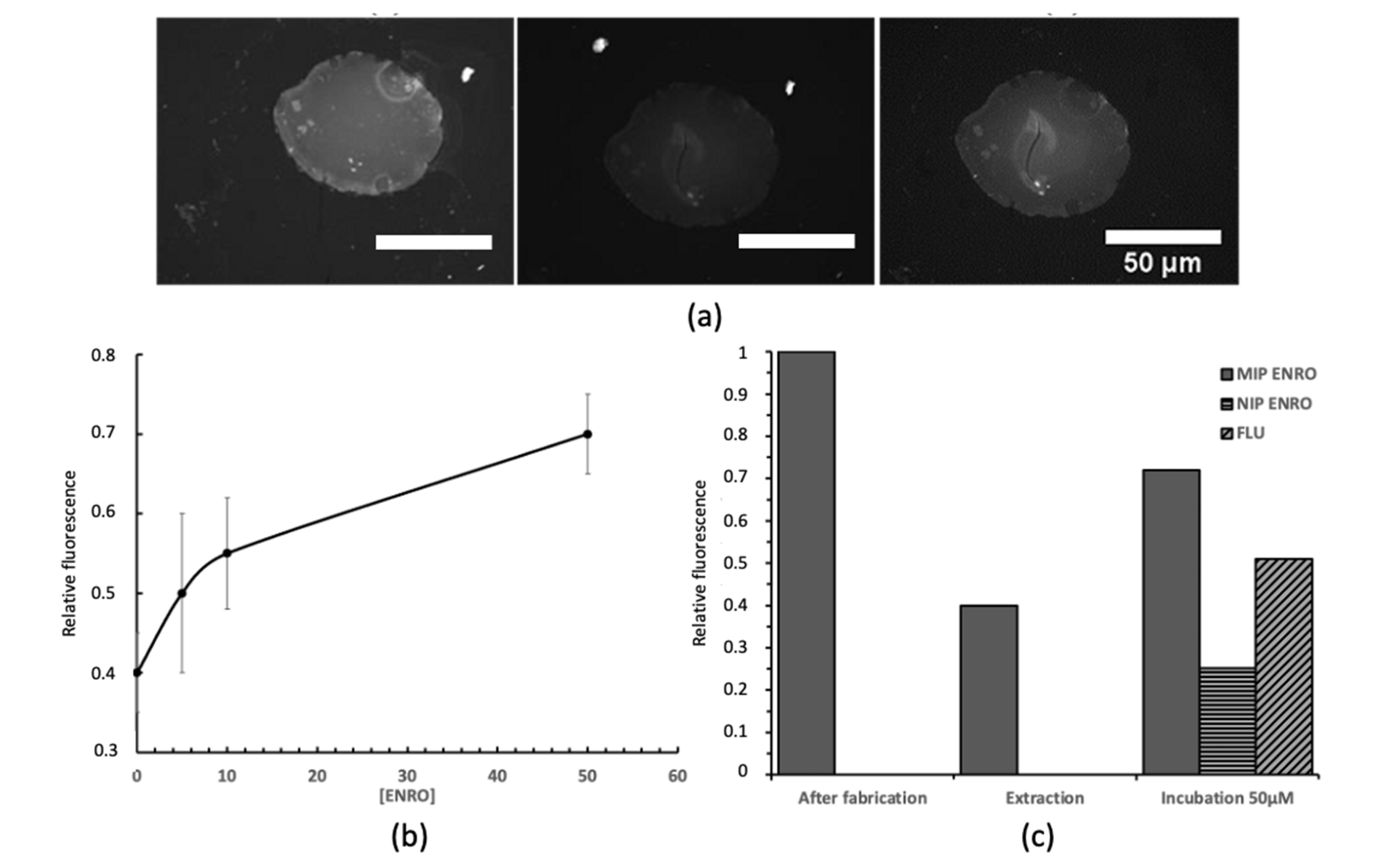
The binding properties of fabricated core–shell structures were analyzed by epifluorescence microscopy. The fluorescence value obtained after fabrication was normalized and used as the reference point. After extraction of the template molecule with acetic acid/ethanol (1:10) (three rounds, 2 h each), the polymer structure was thoroughly rinsed with acetonitrile and dried. The fluorescence intensity after extraction decreased by approximately 60% of the initial value (Figure 6a,c). The remaining fluorescence was attributed to the template, which was trapped in the polymer matrix and could not be extracted from the polymer. Figure 6a shows a MIP-grafted inkjet-printed polymer structure after fabrication, template extraction, and incubation in 50 μM of enrofloxacin, respectively. The increase in fluorescence proved the uptake of the analyte into the binding sites. After incubation for 2 h in 5, 10, and 50 μM of enrofloxacin in acetonitrile solutions, fluorescence images were taken and analyzed. The increasing fluorescence intensity showed a dependence on the analyte concentration (Figure 6b). The binding specificity of the fabricated MIP was evaluated using a chemically identical control–non-imprinted polymer (NIP), and by incubating the structure in 50 μM of flumequine as a structural analog (Figure 6a). The fluorescence increase was significantly less for flumequine than for enrofloxacin, indicating that the MIP specifically targets enrofloxacin. Moreover, a low fluorescence signal was measured on the NIP control after incubation in 50 µM of enrofloxacin, again showing the specific detection of the analyte by the patterned MIP. These results are in good agreement with earlier reports on MIPs targeting enrofloxacin [16,30].
4. Conclusions
In this paper, a microfabrication strategy for microarrays based on MIPs was presented. By inkjet printing of a TRIM-based prepolymer mixture containing an iniferter as a living polymerization initiator, a polymer pattern was generated on a substrate, onto which an MIP shell targeting enrofloxacin was subsequently grafted by reinitiation and post-polymerization. Thus, microfabrication (top-down) and nanofabrication (bottom-up) approaches were merged. The obtained MIP shells were analyzed by fluorescence microscopy and binding characteristics of the MIP shell were found in agreement with the literature, proofing specific target binding (and, thus, the success of the method). One of the advantages of the described method is its versatility. To produce biochips composed of arrays of several different (multiplexed) MIPs, both top-down and bottom-up approaches are suitable. Thus, the inkjet writing can be easily combined with localized photopolymerization (e.g., by projection photolithography), or by localized deposition of the MIP precursors (e.g., approaches similar to soft lithography). Moreover, the grafted MIP can be directly adapted from the huge library of existing MIPs [31] and, therefore, is not limited by adjustments that have to be made for the microfabrication.
Author Contributions
Conceptualization, F.B. and C.A.; methodology, F.B., K.G. and K.H.; investigation, F.B. and K.G.; writing—original draft preparation, F.B. and C.A.; writing—review and editing, C.A. and K.H.; supervision, C.A. and K.H.; funding acquisition, K.H. All authors have read and agreed to the published version of the manuscript.
Funding
This research was funded by the European Union Marie Curie Actions (grant number FP7-PEOPLE-2013-ITN-607590, SAMOSS project).
Institutional Review Board Statement
Not applicable.
Informed Consent Statement
Not applicable.
Data Availability Statement
Not applicable.
Acknowledgments
The authors would like to acknowledge ElorprintTec, a clean-room facility at the University of Bordeaux, for the technical support.
Conflicts of Interest
The authors declare no conflict of interest.
References
- Persidis, A. Biochips. Nat. Biotechnol. 1998, 16, 981–983. [Google Scholar] [CrossRef] [PubMed]
- Kamar, A.Z.; Shamzi, M.H. Desktop fabrication of lab-on-chip devices on flexible substrates: A brief review. Micromachines 2020, 11, 126. [Google Scholar]
- Fruncillo, S.; Su, X.; Liu, H.; Wong, L.S. Lithographic processes for the scalable fabrication of micro-and nanostructures for biochips and biosensors. ACS Sens. 2021, 6, 2002–2024. [Google Scholar] [CrossRef] [PubMed]
- Park, M.; Kang, B.-H.; Jeong, K.-H. Based biochip assays and recent developments: A review. BioChip J. 2018, 12, 1–10. [Google Scholar] [CrossRef]
- Azizipour, N.; Avazpour, R.; Rosenzweig, D.H.; Sawan, M.; Ajji, A. Evolution of biochip technology: A review from lab-on-a-chip to organ-on-a-chip. Micromachines 2020, 11, 599. [Google Scholar] [CrossRef]
- London, J.W.; Diliën, H.; Singla, P.; Peeters, M.; Cleij, T.J.; Van Grinsven, B.; Eersels, K. MIPs for commercial application in low-cost sensors and assays–An overview of the current status quo. Sens. Actuators B Chem. 2020, 325, 128973. [Google Scholar]
- Refaat, D.; Aggour, M.G.; Farghali, A.A.; Mahajan, R.; Wiklander, J.G.; Nicholls, I.A.; Piletsky, S.A. Strategies for molecular imprinting and the evolution of MIP nanoparticles as plastic antibodies—Synthesis and applications. Int. J. Mol. Sci. 2019, 20, 6304. [Google Scholar] [CrossRef]
- Bokeloh, F.; Ayela, C.; Haupt, K. Micro and Nanofabrication Methods of Molecularly Imprinted Polymers. In Molecularly Imprinted Polymers for Analytical Chemistry Application; Royal Society of Chemistry: London, UK, 2018; Chapter 6. [Google Scholar]
- Haupt, K.; Linares, A.V.; Bompart, M.; Bui, B.T. Molecularly imprinting. Top. Curr. Chem. 2012, 325, 1–28. [Google Scholar]
- Paruli, E., III; Soppera, O.; Haupt, K.; Gonzato, C. Photopolymerization and Photostructuring of Molecularly Imprinted Polymers. ACS Appl. Polym. Mater. 2021, 3, 4769–4790. [Google Scholar] [CrossRef]
- Lalo, H.; Ayela, C.; Dague, E.; Vieu, C.; Haupt, K. Nanopatterning molecularly imprinted polymers by soft lithography: A hierarchical approach. Lab Chip 2010, 10, 1316–1318. [Google Scholar] [CrossRef]
- Belmont, A.-S.; Sokuler, M.; Haupt, K.; Heber, L.A. Direct writing of molecularly imprinted microstructures using a nanofountain pen. Appl. Phys. Lett. 2007, 90, 193101. [Google Scholar] [CrossRef]
- Ayela, C.; Dubourg, G.; Pellet, C.; Haupt, K. All-Organic Microelectromechanical Systems Integrating Specific Molecular Recognition–A New Generation of Chemical Sensors. Adv. Mater. 2014, 26, 5876–5879. [Google Scholar] [CrossRef]
- Arrabito, G.; Gulli, D.; Alfano, C.; Pignataro, B. “Writing biochips”: High-resolution droplet-to-droplet manufacturing of analytical platforms. Analyst 2022, 147, 1294–1312. [Google Scholar] [CrossRef]
- Li, X.; Liu, B.; Pei, B.; Chen, J.; Zhou, D.; Peng, J.; Zhang, X.; Jia, W.; Xu, T. Inkjet bioprinting of biomaterials. Chem. Rev. 2020, 120, 10793–10833. [Google Scholar] [CrossRef]
- Caro, E.; Marcé, R.M.; Cormack, P.A.G.; Sherrington, D.C.; Borrull, F. Novel enrofloxacin imprinted polymer applied to the solid-phase extraction of fluorinated quinolones from urine and tissue samples. Anal. Chim. Acta 2006, 562, 145–151. [Google Scholar] [CrossRef]
- Okerman, L.; Noppe, H.; Cornet, V.; De Zutter, L. Microbiological detection of 10 quinolone antibiotic residues and its application to artificially contaminated poultry samples. Food Addit. Contam. 2007, 24, 252–257. [Google Scholar] [CrossRef]
- Wang, D.; Jiang, S.; Liang, Y.; Wang, X.; Zhuang, X.; Tian, C.; Luan, F.; Chen, L. Selective detection of enrofloxacin in biological and environmental samples using a molecularly imprinted electrochemiluminescence sensor based on functionalized copper nanoclusters. Talanta 2022, 236, 122835. [Google Scholar] [CrossRef]
- Wang, W.; Wang, R.; Liao, M.; Kidd, M.T. Rapid detection of enrofloxacin using a localized surface plasmon resonance sensor based on polydopamine molecular imprinted recognition polymer. J. Food Meas. Charact. 2021, 15, 3376–3386. [Google Scholar] [CrossRef]
- Liu, X.; Ren, J.; Su, L.; Gao, X.; Tang, Y.; Ma, T.; Zhu, L.; Li, J. Novel hybrid probe based on double recognition of aptamer-molecularly imprinted polymer grafted on upconversion nanoparticles for enrofloxacin sensing. Biosens. Bioelectron. 2017, 87, 203–208. [Google Scholar] [CrossRef]
- Sigma-Aldrich. Available online: www.sigmaaldrich.com/content/dam/sigma-aldrich/docs/Sigma/Product_Information_Sheet/1/m6514pis.pdf (accessed on 1 April 2021).
- McCloy, R.A.; Rogers, S.; Caldon, C.E.; Lorca, T.; Castro, A.; Burgess, A. Partial inhibition of Cdk1 in G2 phase overrides the SAC and decouples mitotic events. Cell Cycle 2014, 13, 1400–1412. [Google Scholar] [CrossRef]
- Calvert, P. Inkjet printing for materials and devices. Chem. Mater. 2001, 13, 3299–3305. [Google Scholar] [CrossRef]
- Yang, H.; He, Y.; Tuck, C.; Wildman, R.; Ashcroft, I.; Dickens, P.; Hague, R. High viscosity jetting system for 3D reactive inkjet printing. In Proceedings of the 24th Annual International Solid Freeform Fabrication Symposium: An Additive Manufacturing Conference, Austin, TX, USA, 12 August 2013. [Google Scholar]
- Vandevelde, F.; Leichle, T.; Ayela, C.; Bergaud, C.; Nicu, L.; Haupt, K. Direct patterning of molecularly imprinted microdot arrays for sensors and biochips. Langmuir 2007, 23, 6490–6493. [Google Scholar] [CrossRef]
- Beyazit, S.; Bui, B.T.; Haupt, K.; Gonzato, C. Molecularly imprinted polymer nanomaterials and nanocomposites by controlled/living radical polymerization. Prog. Polym. Sci. 2016, 62, 1–21. [Google Scholar] [CrossRef]
- Sellergren, B.; Rückert, B.; Hall, A.J. Layer-by-layer grafting of molecularly imprinted polymers via iniferter modified supports. Adv. Mater. 2002, 14, 1204–1208. [Google Scholar] [CrossRef]
- Barrios, C.A.; Zhenhe, C.; Navarro-Villoslada, F.; López-Romero, D.; Moreno-Bondi, M.C. Molecularly imprinted polymer diffraction grating as label-free optical bio (mimetic) sensor. Biosens. Bioelectron. 2011, 26, 2801–2804. [Google Scholar] [CrossRef]
- Marchyk, N.; Maximilien, J.; Beyazit, S.; Haupt, K.; Bui, B.T. One-pot synthesis of iniferter-bound polystyrene core nanoparticles for the controlled grafting of multilayer shells. Nanoscale 2014, 6, 2872–2878. [Google Scholar] [CrossRef]
- Ton, X.-A.; Acha, V.; Haupt, K.; Bui, B.T. Direct fluorimetric sensing of UV-excited analytes in biological and environmental samples using molecularly imprinted polymer nanoparticles and fluorescence polarization. Biosens. Bioelectron. 2012, 36, 22–28. [Google Scholar] [CrossRef]
- Mipdatabase. Available online: www.mipdatabase.com (accessed on 1 April 2021).
Figure 1.
Design of the inkjet-printed MIP microarray with microscopic images of a pattern of 12 droplets, in a zig-zag shape (left), and the inkjet-printed letters “MIP” (right), both based on TRIM.
Figure 1.
Design of the inkjet-printed MIP microarray with microscopic images of a pattern of 12 droplets, in a zig-zag shape (left), and the inkjet-printed letters “MIP” (right), both based on TRIM.
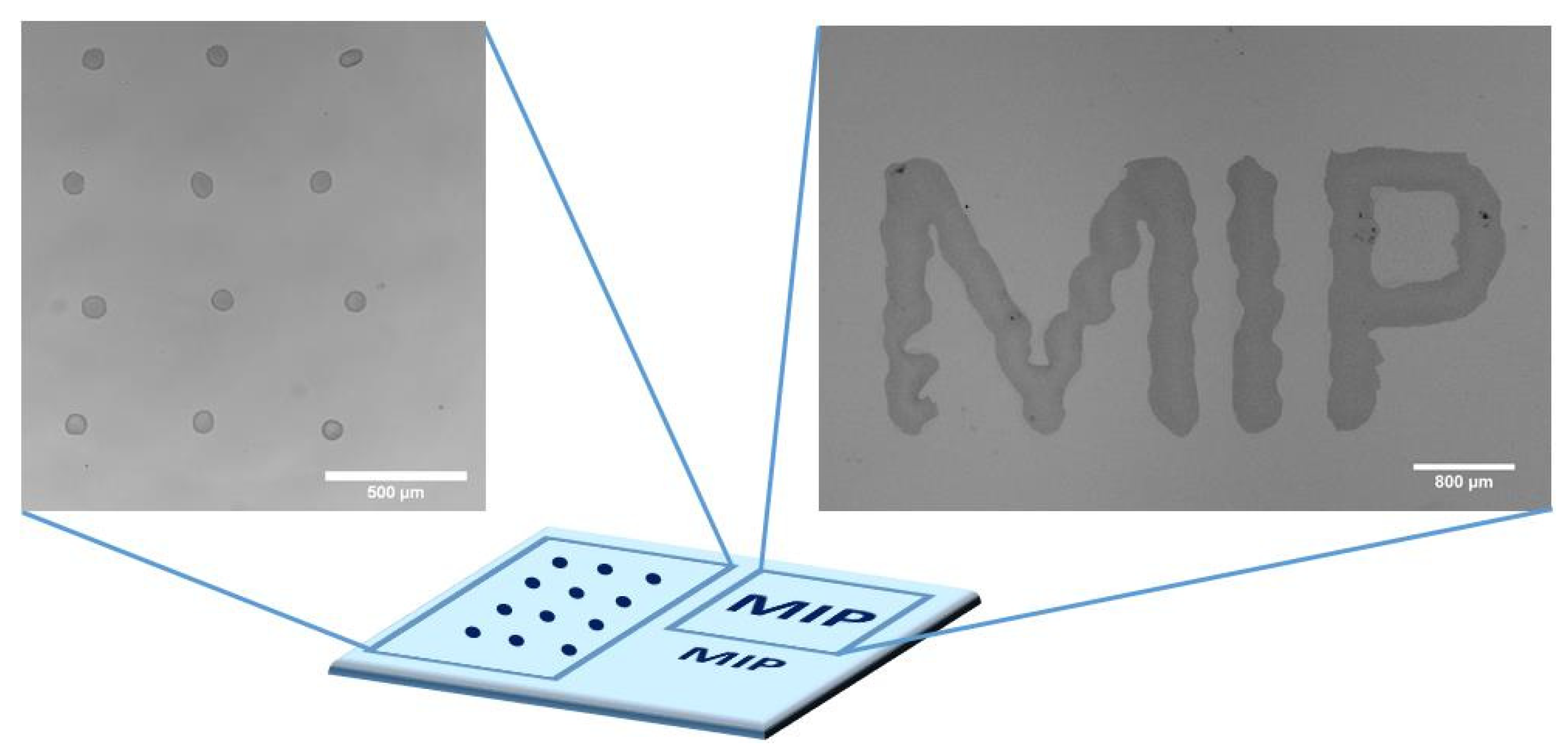
Figure 2.
(a–c) Brightfield images of polymerized “MIP” pattern inkjet-printed with different droplet spacing results in separated droplets, half merged droplets, and total merged droplets. The scale bar is 800 µm; (d) optical profilometer image of the separated inkjet-printed polymer droplets.
Figure 2.
(a–c) Brightfield images of polymerized “MIP” pattern inkjet-printed with different droplet spacing results in separated droplets, half merged droplets, and total merged droplets. The scale bar is 800 µm; (d) optical profilometer image of the separated inkjet-printed polymer droplets.

Figure 3.
Two concepts of inkjet-printed MIP arrays. (A) direct patterning of MIP formulation; (B) Core–shell approach: a core made of TRIM is patterned and polymerized with the iniferter BDC. A shell made of MIP is grafted in a second step by reinitiating the polymerization.
Figure 3.
Two concepts of inkjet-printed MIP arrays. (A) direct patterning of MIP formulation; (B) Core–shell approach: a core made of TRIM is patterned and polymerized with the iniferter BDC. A shell made of MIP is grafted in a second step by reinitiating the polymerization.
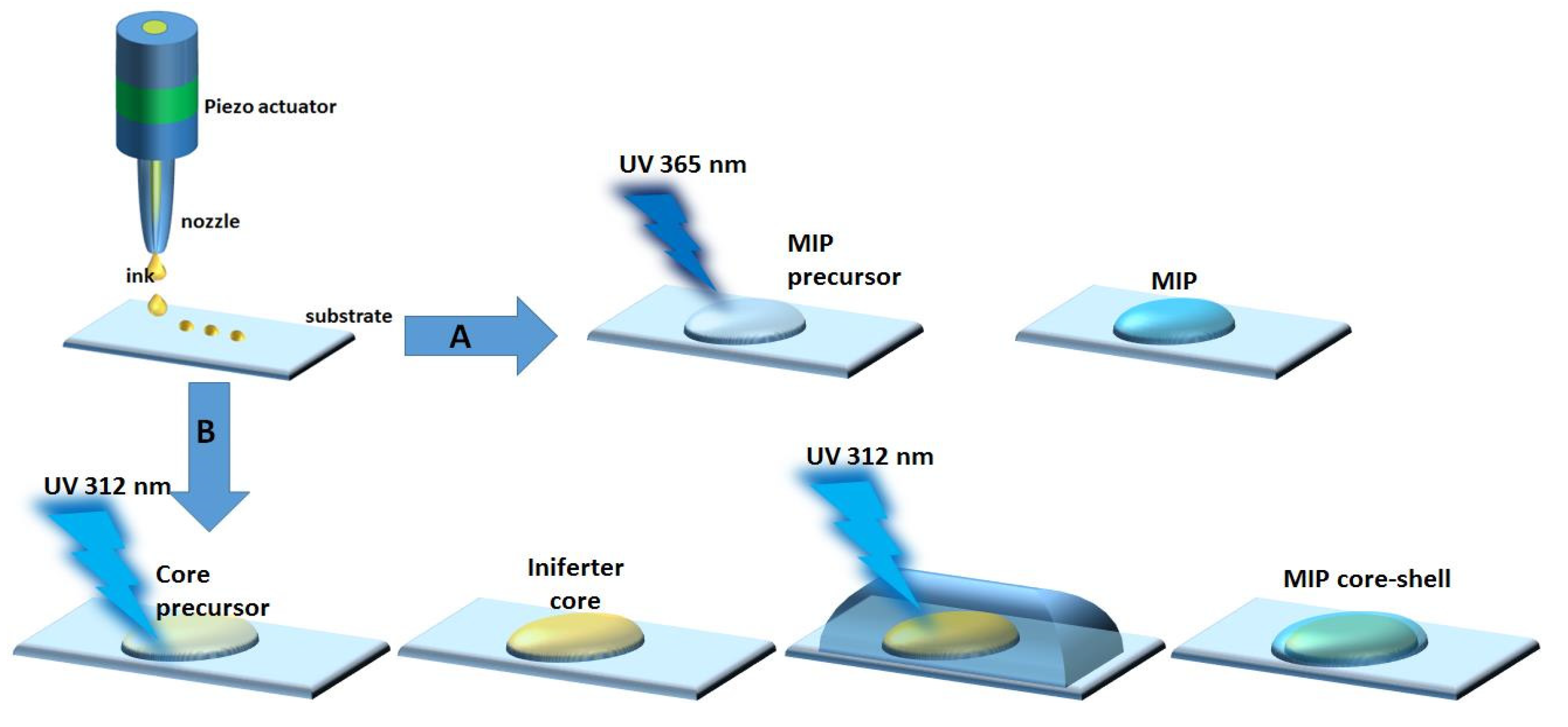
Figure 4.
(a,b) Brightfield images of the MIP pattern and polymerized droplet of a MIP with the solvent butyronitrile. Enrofloxacin precipitates as little needles; (c) polymerized droplets using 1-methylnaphthalene as a solvent.
Figure 4.
(a,b) Brightfield images of the MIP pattern and polymerized droplet of a MIP with the solvent butyronitrile. Enrofloxacin precipitates as little needles; (c) polymerized droplets using 1-methylnaphthalene as a solvent.
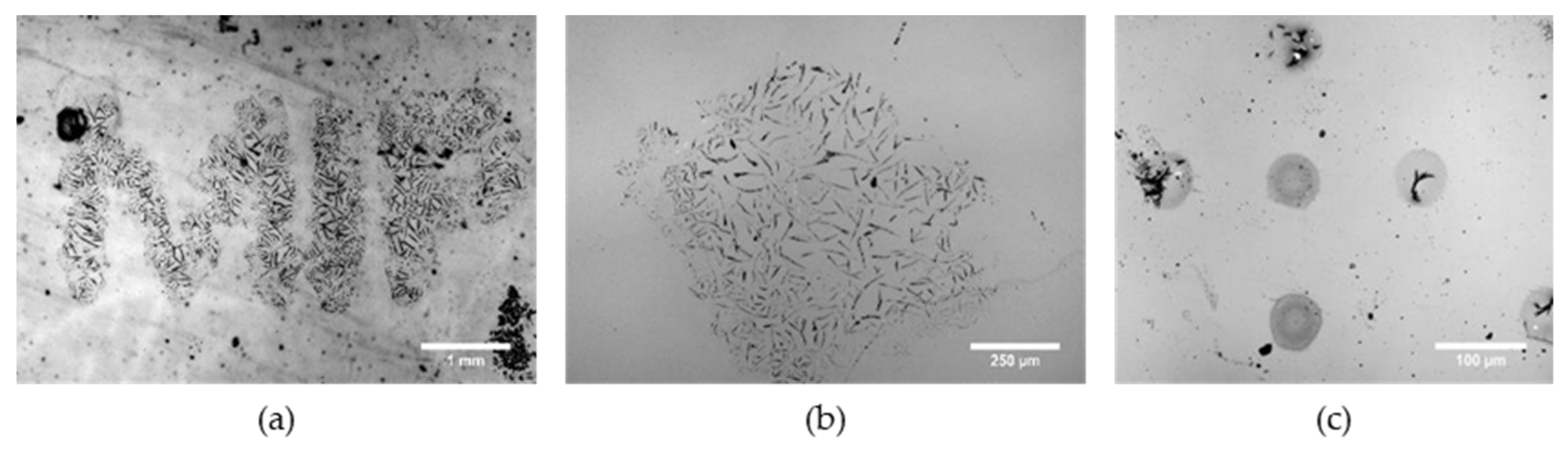
Figure 5.
(a) Brightfield image of the iniferter-polymerized core; (b) corresponding fluorescence image after the core fabrication; (c) resulting fluorescence image after MIP grafting.
Figure 5.
(a) Brightfield image of the iniferter-polymerized core; (b) corresponding fluorescence image after the core fabrication; (c) resulting fluorescence image after MIP grafting.
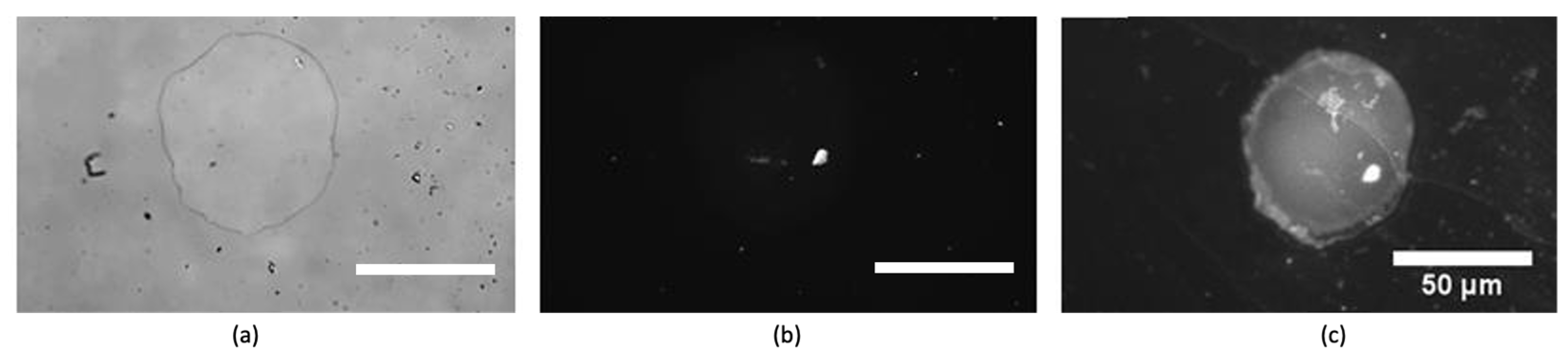
Figure 6.
(a) Enrofloxacin-imprinted structure after fabrication, extraction, and binding 50 μM of enrofloxacin; (b) binding results with 5, 10, and 50 μM of enrofloxacin; the number of experiments n = 3, error bars represent the standard error of the mean; (c) specificity and selectivity studies with 50 μM of enrofloxacin on both MIP and NIP vs. 50 μM of flumequine.
Publisher’s Note: MDPI stays neutral with regard to jurisdictional claims in published maps and institutional affiliations. |
© 2022 by the authors. Licensee MDPI, Basel, Switzerland. This article is an open access article distributed under the terms and conditions of the Creative Commons Attribution (CC BY) license (https://creativecommons.org/licenses/by/4.0/).
Share and Cite
MDPI and ACS Style
Bokeloh, F.; Gibson, K.; Haupt, K.; Ayela, C. Development of a Versatile Strategy for Inkjet-Printed Molecularly Imprinted Polymer Microarrays. Chemosensors 2022, 10, 396. https://doi.org/10.3390/chemosensors10100396
AMA Style
Bokeloh F, Gibson K, Haupt K, Ayela C. Development of a Versatile Strategy for Inkjet-Printed Molecularly Imprinted Polymer Microarrays. Chemosensors. 2022; 10(10):396. https://doi.org/10.3390/chemosensors10100396
Chicago/Turabian StyleBokeloh, Frank, Kasia Gibson, Karsten Haupt, and Cédric Ayela. 2022. "Development of a Versatile Strategy for Inkjet-Printed Molecularly Imprinted Polymer Microarrays" Chemosensors 10, no. 10: 396. https://doi.org/10.3390/chemosensors10100396
Note that from the first issue of 2016, this journal uses article numbers instead of page numbers. See further details here.