Article

In-Parallel Polar Monitoring of Chemiluminescence Emission Anisotropy at the Solid–Liquid Interface by an Optical Fiber Radial Array

1
Institute of Applied Physics “Nello Carrara”, National Research Council, Via Madonna del Piano 10, 50019 Sesto Fiorentino (FI), Italy
2
Department of Chemistry “Giacomo Ciamician”, Alma Mater Studiorum—University of Bologna, via Selmi 2, 40126 Bologna (BO), Italy
*
Authors to whom correspondence should be addressed.
Chemosensors 2020, 8(1), 18; https://doi.org/10.3390/chemosensors8010018
Submission received: 21 January 2020 / Revised: 14 February 2020 / Accepted: 22 February 2020 / Published: 29 February 2020
(This article belongs to the Collection Optical Chemosensors and Biosensors)

Abstract

:
Chemiluminescence (CL) detection is widely employed in biosensors and miniaturized analytical devices since it offers high detectability and flexible device design (there are no geometry requirements for the measurement cell, except the ability to collect the largest fraction of emitted photons). Although the emission anisotropy phenomenon for an emitting dipole bound to the interface between two media with different refractive index is well known for fluorescence, it is still poorly investigated for CL reactions, in which the excited-state reaction products can diffuse in solution before the photon emission event. In this paper, we propose a simple method for the real-time evaluation of the CL emission anisotropy based on a radial array of optical fibers, embedded in a poly(methyl methacrylate) semicylinder and coupled with a Charge-Coupled Device (CCD) camera through a suitable interface. The polar-time evolutions of the CL emission have been studied for catalyzing enzymes immobilized onto a solid surface (heterogeneous configuration) or free in solution (homogeneous configuration). Evidence of the anisotropy phenomenon is observed, indicating that the lifetime of the excited-state products of the enzyme-catalyzed reactions is shorter than the time required for their diffusion in solution at a distance at which the CL can be considered isotropic. These results open new perspectives in the development of CL-based miniaturized analytical devices.

1. Introduction

Chemiluminescence (CL, i.e., the light emission originating from a strongly exergonic chemical reaction yielding a product in its electronically excited state) is an optical detection method which, due to its intrinsic characteristics, is gaining a growing interest in the development of high-performance biosensing devices [1,2,3]. In fact, when compared to other optical detection principles, such as absorption or fluorescence, CL offers considerable advantages including a high detectability even in low volumes, due to the possibility of producing photons “in the dark”, thus minimizing any other nonspecific signal contribution coming from excitation photons and maximizing the resulting signal-to-noise ratio. As the CL light signal is the result of a chemical reaction, no external source, together with the connected filtering apparatus, is requested. All these features can lead to the development of very simple and miniaturized analytical devices [4,5,6,7]. In many bioanalytical applications, such as the CL-based enzyme-linked immunoassay, the CL reaction is catalyzed by an enzyme conjugated with a bio-specific capture element bound on a solid surface (e.g., glass, polymer, or paper) [8,9,10,11,12]. This means that the light-emitting product of the CL enzymatic reaction can be represented as a whole as an electromagnetic dipole emitter generated in the proximity of a surface.
The anisotropic emission of electric and/or magnetic dipoles, when the distance from a dielectric interface is small or comparable with the emitted wavelength, is a well-known phenomenon [13,14,15,16,17,18,19]. Indeed, when a light emitter is located at the interface between two dielectric media with different refractive indexes (n1 and n2, with n2 > n1), the majority of the light signal propagates in the denser medium with higher refractive index (n2) at angles θ above the critical angle θcc = sin−1 (n1/n2)) [18]. If the denser medium is a substrate with flat and parallel faces (e.g., a microscope slide), most of the emitted light will propagate through successive total internal reflections inside the substrate. In the case of a fluorescence signal, this propagation regime beyond the critical angle is called supercritical angle fluorescence (SAF). The other contribution to the overall emission is represented by the refracted light, which is emitted at angles θ below the critical angle θc, generally referred to as undercritical angle fluorescence (UAF) [20,21,22,23]. Therefore, while it is possible to collect the UAF contribution by placing a detector close to the bottom face of the substrate, the same cannot be done for the SAF component, which, by its nature, is undetected because it remains trapped inside the denser medium. Consequently, this phenomenon must be taken into serious consideration in order to optimize the signal collection efficiency of optical devices and increase their performance in terms of sensitivity [18,24,25,26,27,28,29].
Although the anisotropic emission has been deeply investigated for fluorescence emitters, the same cannot be said for CL reactions. In the case of CL reactions, the emission phenomenon is even more complicated because, even if the catalyzing enzyme is immobilized on the solid surface, the excited-state product of the reaction could diffuse in the solution prior to the photon emission [30]. Therefore, depending on the properties of the emitter (i.e., excited-state lifetime and diffusion coefficient), light emission does not necessarily take place in proximity of the surface.
Evidence of a strongly polarized and directional emission has been reported by M.H. Chowdhury et al. in their studies on surface plasmon-coupled chemiluminescence (SPCC), where the light radiation produced by a CL reaction in solution was coupled to the surface plasmons in glass slides coated with a metal thin film. The authors attributed the nature of this emission to the surface plasmons, rather than to the luminophores themselves. For such studies, the authors developed a rotary stage in which a single optical fiber connected to a spectrometer collected the light at a given angle around the sample chamber [31,32], with the limitation of a time-consuming polar scanning.
In this work we propose a simple method for the real-time evaluation of the emission anisotropy of CL enzyme reactions at the liquid–solid interface, based on an array of plastic multimode optical fibers. The optical fibers are radially placed at fixed polar angles to monitor, as a function of the angle, the CL signal intensity. The input face of each fiber is embedded in a plastic semicylinder while the other face is imaged by a CCD camera through a suitable interface. Experiments were conducted by using two different enzymes, namely horseradish peroxidase (HRP) and alkaline phosphatase (ALP), immobilized on a poly(methyl methacrylate) (PMMA) slide (heterogeneous configuration), as well as using HRP in solution (homogeneous configuration). Evidence of the anisotropy phenomenon is reported for all the cases examined. As it will be shown in the experimental section, HRP and ALP in the heterogeneous configuration, although showing different kinetics of the CL reactions, displayed similar polar distributions of their emission, while a time-dependent behavior of the polar distribution was evidenced for HRP in the homogeneous configuration.

2. Materials and Methods

2.1. Optical Setup and Methods

Figure 1 sketches the experimental setup adopted for collecting the CL signal and studying its behavior at the interface in terms of emission anisotropy (i.e., polar distribution of the emission). All transparent elements were made of PMMA, with a mean refractive index nPMMA = 1.50 in the 420–480 nm wavelength interval (the HRP- and ALP-catalyzed CL emissions have maxima at about 425 and 470 nm, respectively).
Multimode PMMA optical fibers Broadcom HFBR-RUS100Z (Broadcom, San Jose, CA, USA) were used, characterized by a diameter of 1 mm and a numerical aperture (NA) of 0.47 and cut in pieces 60 cm in length. The ends of each fiber were accurately polished by means of a lapping machine, using aluminum oxide and silicon carbide abrasive disks with different grind size from 12 μm down to 0.3 μm (Buehler FibrMet Disc, PSA Backed, 4″). All Buehler products were obtained from Buehler (Lake Bluff, IL, USA).
A PMMA semicylinder was obtained by cutting a PMMA rod (35 mm in length, 40 mm in diameter) along a plane parallel to the cylinder axis and 1 mm far from it (see Figure 2). The obtained rectangular flat top surface (35 mm × 40 mm) was manually polished by using a nonabrasive cloth (Buehler microcloth PSA 2-7/8″) and colloidal diamond suspension (Buehler MetaDiTM Supreme—Polycrystalline Diamond Suspension) with a grit of 0.25 μm. The semicylinder block was then drilled in correspondence with its circular outer surface in order to realize eleven radial cylindrical holes (1.1 mm in diameter, 4 mm in depth) with a constant azimuthal angular spacing of 15°, necessary to house the input ends of the optical fibers used for CL signal collection. The fibers were glued inside the holes with the NOA 68 optical glue (Norland Products Inc., Cranbury, NJ, USA).
A PMMA slide (microfluidic ChipShop, Jena, Germany), with a thickness of 1 mm, was set on the top of the PMMA semicylinder and used as support for the CL reaction. With reference to Figure 2, considering that the height of the semicylinder is 19 mm (i.e., 1 mm less than the cylinder radius), the upper surface of the 1-mm-thick slide will be coincident with the cylinder axial plane. During the experiments, a refractive index matching oil (pure glycerol from Sigma-Aldrich, St. Louis, MO, USA, with a refractive index nOIL = 1.48) was used to improve the optical coupling condition of the PMMA slide with the underlying PMMA semicylinder.
The optical configuration allowed the maximum efficiency of light collection by optical fibers. Indeed, if r = 0.5 mm is the radius of the optical fiber and D = 16 mm is the distance between the fiber face and the CL drop, the acceptance angle, or angular resolution, for every fiber, assuming a point emitter placed on the semicylinder axis, can be calculated as:
2 t a n 1 ( r D ) = 3.58 °
This value of the acceptance angle is under the numerical aperture of the fiber, so all the light reaching the fiber input end will be conveyed to the CCD camera.
The eleven optical fiber output ends were fixed in the holes of a support obtained by drilling a parallelepiped of black polyvinylchloride (PVC) polymer (17 mm × 13 mm × 10 mm, see Figure 1) to obtain a 4 × 3 holes matrix (1.1 mm diameter, 5 mm spacing). Such support acted as an interface between the collecting system (PMMA semicylinder and plastic fibers) and the imaging detector (cooled MZ-2PRO CCD camera, MagZero, Pordenone, Italy) equipped for lensless contact imaging through a round fiber optic taper (25 to 11 mm, Edmund Optics, Barrington, NJ, USA) placed in contact with the CCD sensor [33]. Since each position in the 4 × 3 holes matrix of the support corresponded to a specific optical fiber, the CL emissions at different angles can be acquired independently and simultaneously (the twelfth position of the matrix was used to measure the background signal of the CCD camera). The measurements were performed inside a black box to avoid any spurious light contribution from the environment that could interfere with the measurement.

2.2. Reagents and Reaction Protocols

The enzymes HRP (type VI-A, from horseradish) and ALP (from bovine intestinal mucosa) were purchased from Sigma-Aldrich. Enzyme solutions were prepared in 0.1 M phosphate-buffered saline (PBS), pH 7.7. The Super Signal ELISA Femto CL cocktail for HRP was purchased from Thermo Fisher Scientific (Rockford, IL, USA), while the Lumiphos Plus CL cocktail for ALP was from Lumigen (Southfield, MI, USA).
Figure 3 illustrates the heterogeneous and homogeneous configurations adopted in the experiments for measuring the polar distribution of the emission from enzyme-catalyzed CL reactions. For enzyme immobilization (heterogeneous configuration), the PMMA slides were first functionalized by one-minute dip-coating in a 2 mM Eudragit L100 copolymer (Evonik Degussa GmbH, Düsseldorf, Germany) ethanol solution, then air-dried to form a polymeric thin film on the surface. Eudragit L100 is an anionic copolymer made of methacrylic acid and methyl methacrylate used to provide carboxylic (–COOH) functional groups for the binding of biospecific molecules. The slide surfaces were activated with 2 mM 1-ethyl-3-[3-dimethylaminopropyl] carbodiimide hydrochloride (EDC) and 5 mM N-hydroxysuccinimide (NHS) (Thermo Fisher Scientific). Then, 1 μL of 1 µg/mL enzyme solution (HRP or ALP) was deposited on the activated PMMA slide surface and incubated for 1 h in a humid chamber at room temperature. The slides were then thoroughly washed with PBS and dried under a nitrogen stream.
For the measurement, the slide was positioned on the PMMA semicylinder with the spot of immobilized enzyme placed in correspondence with the focus of the optical collecting system, univocally identified by the axis of the PMMA semicylinder and the plane of the fibers. Then, 10 µL of CL cocktail (Super Signal ELISA Femto or Lumiphos Plus for HRP or ALP, respectively) were added and CL images were acquired.
A similar procedure was adopted for the measurements in the homogeneous configuration, except for the fact that pristine PMMA slides were used. For each measurement, 1 μL of 10 ng/mL HRP enzyme solution and 9 μL of Super Signal ELISA Femto CL cocktail were dispensed on the slide in correspondence with the focus of the optical collecting system and CL images were acquired.

2.3. Signal Acquisition and Processing

Images (grayscale images, 16-bit depth in the FITS file format) were acquired at regular time intervals employing a 5-s integration time and analyzed with the freely available open source ImageJ software [34]. The overall signal of each spot (corresponding to a fiber output end and, therefore, proportional to the CL emission intensity at the polar angle of the fiber) was evaluated by integration over the whole spot area. An example of a frame is reported in Figure 4.
The twelfth position of the matrix, indicated in Figure 4 as BG- σr, was used to measure the background signal of the CCD camera and for the estimation of the statistical relative error σr of the measurements, calculated as the standard deviation–average signal ratio of said point.

3. Results and Discussion

3.1. Chemiluminescence Systems

Chemiluminescent measurements were performed by using the CL reactions catalyzed by HRP or ALP enzymes, which are widely used in bioanalytical applications, in particular in enzyme-based assays and in binding assays such as gene probe hybridization and immunoassays.
Calf intestinal ALP is a 160 kDa enzyme often detected by means of 1,2-dioxetane derivatives as enzymatic substrates. In this work, the Lumiphos Plus CL cocktail for ALP containing 4-methoxy-4-(3-phosphatephenyl)spiro[1,2-dioxetane-3,2′-adamantane] disodium salt (AMPPD) and an enhancer (which increases the duration and intensity of the emission) was employed. The catalytic action of the enzyme on AMPPD results in dephosphorylation of the aryl phosphate moiety of the dioxetane with subsequent cleavage of the 1,2-dioxetane ring and production of a phenolate moiety in its excited state [35].
Horseradish peroxidase, which is largely employed in bioanalytical assays owing to its rather small dimension (44 kDa) and high turnover rate, catalyzes the oxidation reaction of luminol, which produces 3-aminophthalate in its excited state. In this work, a commercial CL cocktail containing an N-alkylated phenothiazine enhancer and 4-morpholinopyridine as the acylation catalyst was employed. These molecules are added to the system to increase the enzyme turnover number and the equilibrium concentration of the key intermediate luminol radical anion, providing more intense and prolonged light emission [36].

3.2. Heterogeneous Configuration

In the heterogeneous configuration, the enzyme, either ALP or HRP, was immobilized onto the Eudragit functionalized PMMA slide. A drop of CL reaction cocktail was then deposited on the surface of the slide in correspondence with the axis of the optical collecting system (Figure 2).
A representative CL image acquired by the CCD camera is depicted in Figure 4. The elliptical shape of the spots is generated by a slight distortion introduced by the fiber taper adapter, considering also that the end of the taper is about 2 mm distant from the camera sensor. Figure 5a shows the kinetic profile of the emission obtained for ALP immobilized on the PMMA surface (i.e., the sum of the signals collected by the eleven fibers). The error bars were calculated considering the relative standard deviation σr = 1% calculated on the 15 samples acquired in the BG-σr point. The intensity of the CL emission increases with time in accordance to the typical kinetics of the CL reaction of 1,2-dioxetane substrates catalyzed by ALP. Indeed, such reactions usually show slow emission kinetics, and the CL signal often reaches a plateau 20–30 min after the start of the reaction [37]. A similar behavior can be observed in Figure 5b where the CL emissions at the various angles (i.e., the average of the signals measured for each couple of fibers at symmetrical angles) are reported as a function of time.
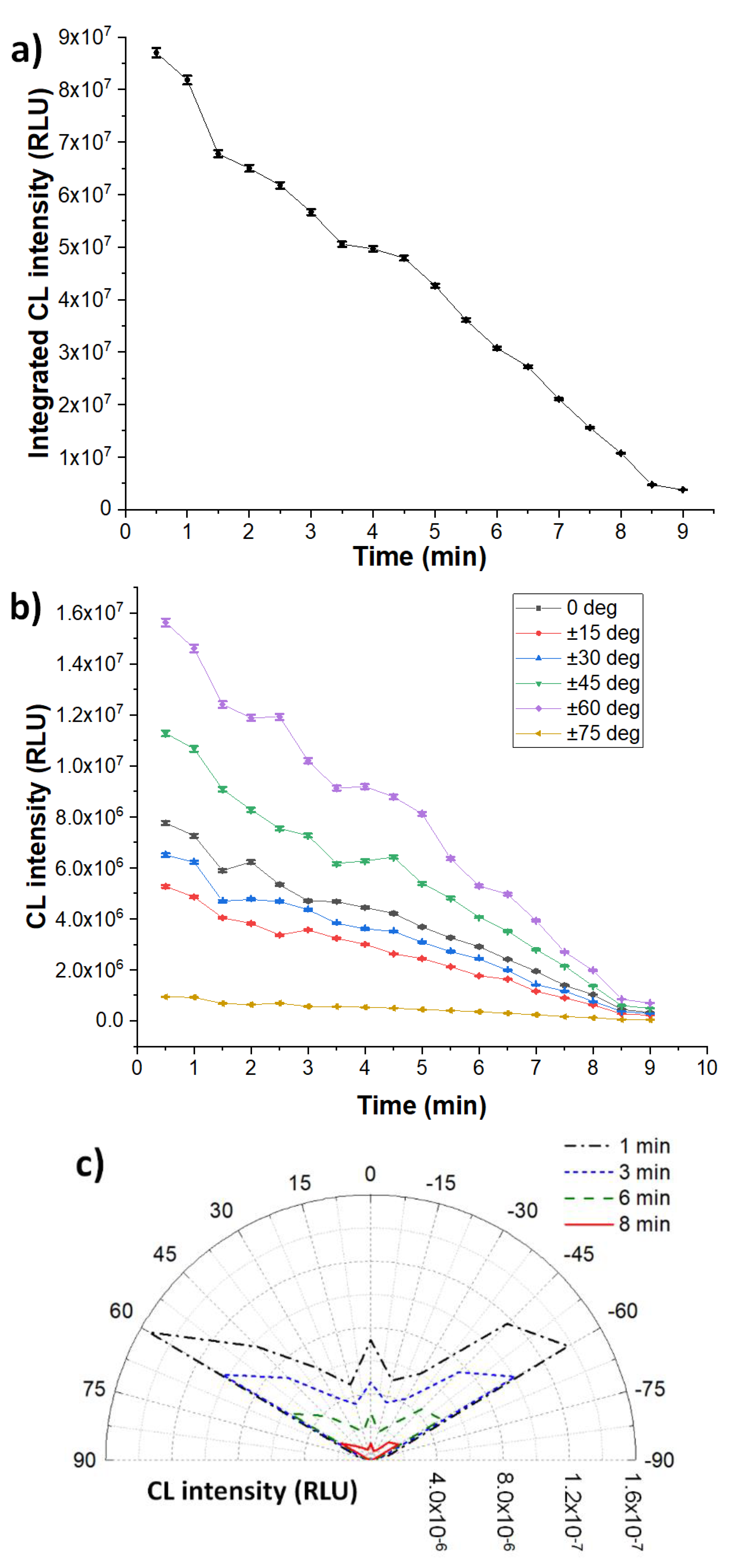
Figure 5b clearly shows that the intensity of the CL emission also depends on the polar angle. Indeed, the CL emission is strongly anisotropic (Figure 5c), with maxima at ±60° angles that are very close to the critical angle of the PMMA–buffer interface ( θ c , P M M A b u f f e r = s i n 1 ( 1.34 / 1.50 ) 63 ° ). This indicated that the CL emission occurs, on average, close to the PMMA surface, in particular within a distance from the surface less than or comparable with the CL emission wavelength (i.e., around 470 nm). Thus, the lifetime of the excited product of the enzyme-catalyzed reaction is significantly shorter than the time required for its diffusion far from the surface. As expected, the polar distribution remains practically unchanged over time, demonstrating that the CL emission occurs close to the PMMA surface for the entire duration of the reaction.
In the case of immobilized HRP, the kinetic profile of the overall CL emission (Figure 6a) is quite different, since the maximum emission intensity is immediately reached, then the signal decreases with time. Again, the behavior is in line with the typical kinetics of the luminol/peroxide/enhancer CL system in the presence of HRP, characterized by a rapid onset of the CL emission followed by a gradual decrease due to reagent consumption and enzyme degradation caused by the CL radical reaction [37].
The kinetic profiles of the CL signals measured at the two symmetrical angles are reported in Figure 6b, while the resulting polar distribution of the emission at different times is depicted in Figure 6c. The error bars were calculated considering the relative standard deviation σr = 1% calculated for the 18 samples acquired in the BG-σr point. As already observed for the immobilized ALP, the CL emission is markedly anisotropic and the maximum emission is at ±60° angles, again confirming the proximity of the CL emitters to the PMMA surface.
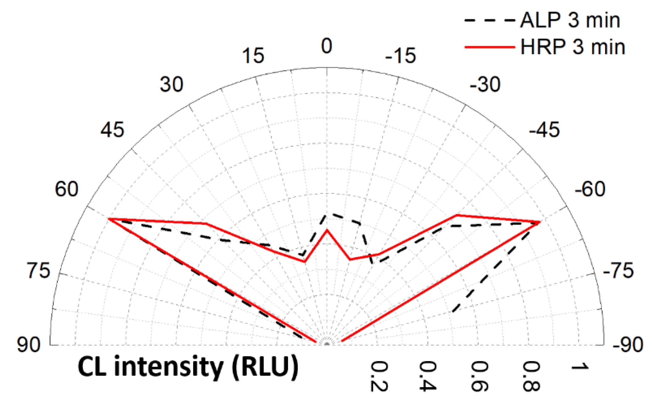
Figure 7 shows the comparison between the polar distributions of the CL emissions observed for immobilized ALP and HRP. It is evident that the emissions display the same anisotropy independently from the catalyzing enzyme and the absolute intensity of the emission.

3.3. Homogeneous Configuration

The CL emission in the homogeneous configuration was investigated to demonstrate that the employed measurement system was able to correctly differentiate between isotropic and anisotropic CL emission. In this configuration, the CL reaction cocktail containing the enzyme HRP was deposited onto pristine PMMA slide in the same position defined by the axis of the optical detection system.
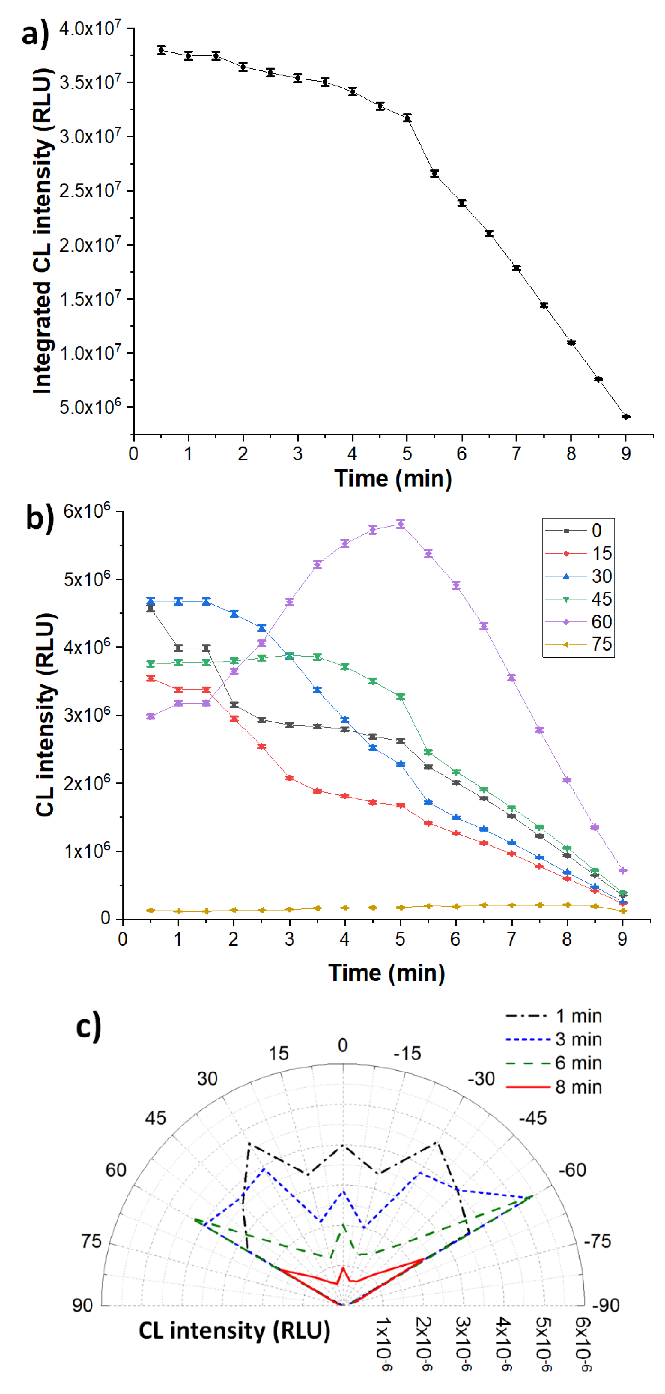
As far as the HRP in solution is concerned, the kinetic profile of the CL emission is quite similar to that of the immobilized HRP (Figure 8a). However, the kinetic profiles of the CL signals measured at the two symmetrical angles (Figure 8b) and the resulting polar distribution of the emission at different times (Figure 8c) display a different behavior. The error bars were calculated considering the relative standard deviation σr = 1% calculated for the 18 samples acquired in the BG-σr point. Indeed, as expected, the CL emission is almost isotropic at short reaction times, according to the fact that the CL emitters produced by the chemical reaction are homogeneously distributed in the solution volume. However, with increasing time, the intensity of the CL emission decreases while its polar distribution evolves to anisotropy, becoming similar to that observed for HRP in the heterogeneous configuration. This can be reasonably due to the gradual absorption of HRP onto the PMMA surface, which moves the average reaction/emission volume closer to the surface. Indeed, it has been reported that protein adsorption on the surface of pristine PMMA, which occurs through interaction of the hydrophobic domains of the protein with the polymer surface, is quite fast, reaching a significant degree of surface coverage after only 10 min of incubation [38,39]. This observation demonstrated the possibility to use the developed system to monitor the absorption of the HRP enzyme on a surface in real time.

4. Conclusions

In this manuscript, an optical detection methodology for the real-time polar monitoring of CL emission has been described. The optical device consisted of a PMMA semicylinder with a radial array of eleven collecting optical fibers. The output ends of the fibers were faced to a CCD camera, which allowed the single-shot acquisition of the optical signals from all fibers. In this way, it was possible to evaluate the polar distribution of the CL emission from a chemical reaction that took place at the liquid–solid boundary and its evolution with time. With this methodology, it is worth observing that the angular resolution can be easily improved by increasing the number of fibers and/or decreasing the core diameter of each fiber.
Two different configurations have been studied: heterogeneous (HRP or ALP enzymes bound on a PMMA surface) and homogeneous (HRP enzyme free in solution). Experimental results showed a markedly anisotropic emission in the heterogeneous configuration, confirming that the photon emission resulting from the decay of the excited-state products of the CL reaction catalyzed by immobilized enzymes occurred close to the PMMA surface. It is worth noting that this behavior might not be confirmed for other CL systems, being dependent on the lifetime of intermediate products of the CL reaction [30]. Additionally, the presence of enhancers in the CL substrate could also affect the polar behavior of the emission (e.g., by introducing energy acceptors that represent the actual emitting species of the CL reaction). For the homogeneous configuration, the CL emission was almost isotropic at short reaction times, while evolving towards an anisotropic emission over time. This suggested that absorption of the enzyme on the PMMA surface took place during the measurement, bringing the reaction volume closer and closer to the PMMA surface.
The observed anisotropic behavior of the CL emission occurring when the enzymes catalyzing the CL reaction are in close proximity to the boundary between two dielectric media with different refractive indexes opens new perspectives in the design of CL biosensors. This phenomenon must be taken into consideration when designing miniaturized CL-based analytical devices or even exploited to improve the signal collection efficiency. Indeed, in many biosensor configurations the detector is placed close to the bottom part of a transparent substrate on which the CL reaction takes place. With this setup, a large fraction of emitted photons remains undetected, thus greatly reducing assay detectability. On the contrary, anisotropic coupling of the CL emission to a transparent substrate could be used to guide the emitted photons towards the light detector, thus improving light collection efficiency without using dedicated optics.

Author Contributions

Conceptualization, C.T., M.M.; methodology, C.T., S.B., M.M.; formal analysis, M.G., C.T., S.B.; investigation, S.B., C.T., M.Z., E.M.; resources, M.Z., S.B., C.T.; data curation, E.M.; writing—original draft preparation, S.B., C.T., M.M.; writing—review and editing, S.T., A.G., F.B., M.G.; visualization, S.B., C.T., S.T., M.M., A.G.; supervision, A.R., F.B.; project administration, M.M.; funding acquisition, M.M., S.T. All authors have read and agreed to the published version of the manuscript.

Funding

This work was supported by the Italian Ministry for University and Research in the framework of “Bando PRIN 2017”, project number 2017YER72K.

Conflicts of Interest

The authors declare no conflict of interest. The funders had no role in the design of the study; in the collection, analyses, or interpretation of data; in the writing of the manuscript, or in the decision to publish the results.

References

  1. Pinto Da Silva, L.; Esteves Da Silva, J.C.G. Firefly chemiluminescence and bioluminescence: Efficient generation of excited states. ChemPhysChem 2012, 13, 2257–2262. [Google Scholar] [CrossRef]
  2. Vacher, M.; Fdez Galván, I.; Ding, B.W.; Schramm, S.; Berraud-Pache, R.; Naumov, P.; Ferré, N.; Liu, Y.J.; Navizet, I.; Roca-Sanjuán, D.; et al. Chemi- and Bioluminescence of Cyclic Peroxides. Chem. Rev. 2018, 118, 6927–6974. [Google Scholar] [CrossRef]
  3. Magalhães, C.M.; Esteves da Silva, J.C.G.; Pinto da Silva, L. Chemiluminescence and Bioluminescence as an Excitation Source in the Photodynamic Therapy of Cancer: A Critical Review. ChemPhysChem 2016, 2286–2294. [Google Scholar] [CrossRef]
  4. Pires, N.; Dong, T.; Hanke, U.; Hoivik, N. Recent Developments in Optical Detection Technologies in Lab-on-a-Chip Devices for Biosensing Applications. Sensors 2014, 14, 15458–15479. [Google Scholar] [CrossRef] [Green Version]
  5. Mirasoli, M.; Guardigli, M.; Michelini, E.; Roda, A. Recent advancements in chemical luminescence-based lab-on-chip and microfluidic platforms for bioanalysis. J. Pharm. Biomed. Anal. 2014, 87, 36–52. [Google Scholar] [CrossRef]
  6. Roda, A.; Mirasoli, M.; Michelini, E.; Di Fusco, M.; Zangheri, M.; Cevenini, L.; Roda, B.; Simoni, P. Progress in chemical luminescence-based biosensors: A critical review. Biosens. Bioelectron. 2016, 76, 164–179. [Google Scholar] [CrossRef]
  7. Alahmad, W.; Uraisin, K.; Nacapricha, D.; Kaneta, T. A miniaturized chemiluminescence detection system for a microfluidic paper-based analytical device and its application to the determination of chromium(III). Anal. Methods 2016, 8, 5414–5420. [Google Scholar] [CrossRef]
  8. Marquette, C.A.; Blum, L.J. Chemiluminescent enzyme immunoassays: a review of bioanalytical applications. Bioanalysis 2009, 1, 1259–1269. [Google Scholar] [CrossRef]
  9. Chong, R.; Rho, J.E.R.; Yoon, H.J.; Rho, T.H.D.; Park, P.S.; Kim, Y.H.; Lee, J.H. 1,1’-Oxalyldiimidazole chemiluminescent enzyme immunoassay capable of simultaneously sensing multiple markers. Biosens. Bioelectron. 2012, 32, 19–23. [Google Scholar] [CrossRef]
  10. Fereja, T.H.; Hymete, A.; Gunasekaran, T. A Recent Review on Chemiluminescence Reaction, Principle and Application on Pharmaceutical Analysis. ISRN Spectrosc. 2013, 2013, 1–12. [Google Scholar] [CrossRef] [Green Version]
  11. Xie, H.; Wang, Z.; Kong, W.; Wang, L.; Fu, Z. A novel enzyme-immobilized flow cell used as end-column chemiluminescent detection interface in open-tubular capillary electrochromatography. Analyst 2013, 138, 1107–1113. [Google Scholar] [CrossRef] [PubMed]
  12. Zangheri, M.; Di Nardo, F.; Mirasoli, M.; Anfossi, L.; Nascetti, A.; Caputo, D.; De Cesare, G.; Guardigli, M.; Baggiani, C.; Roda, A. Chemiluminescence lateral flow immunoassay cartridge with integrated amorphous silicon photosensors array for human serum albumin detection in urine samples. Anal. Bioanal. Chem. 2016, 408, 8869–8879. [Google Scholar] [CrossRef] [PubMed] [Green Version]
  13. Lukosz, W.; Kunz, R.E. Light emission by magnetic and electric dipoles close to a plane dielectric interface II Radiation patterns of perpendicuar oriented dipoles. J. Opt. Soc. Am. 1977, 67, 1615–1619. [Google Scholar] [CrossRef]
  14. Lukosz, W. Light emission by magnetic and electric dipoles close to a plane dielectric interface III Radiation patterns of dipoles with arbitrary orientation. J. Opt. Soc. Am. 1979, 69, 1495. [Google Scholar] [CrossRef]
  15. Thompson, N.L.; Burghardt, T.P. Measurement of spatial and orientational distribution of fluorophores near planar dielectric interfaces. Biophys. Chem. 1986, 25, 91–97. [Google Scholar] [CrossRef]
  16. Enderlein, J.; Ruckstuhl, T.; Seeger, S. Highly efficient optical detection of surface-generated fluorescence. Appl. Opt. 1999, 38, 724. [Google Scholar] [CrossRef]
  17. Polerecký, L.; Hamrle, J.; MacCraith, B.D. Theory of the radiation of dipoles placed within a multilayer system. Appl. Opt. 2000, 39, 3968. [Google Scholar] [CrossRef]
  18. Blue, R.; Kent, N.; Polerecky, L.; McEvoy, H.; Gray, D.; MacCraith, B.D. Platform for enhanced detection efficiency in luminescence-based sensors. Electr. Lett. 2005, 41, 682–684. [Google Scholar] [CrossRef]
  19. Dasallas, L.L.; Jaculbia, R.B.; Balois, M.V.; Garcia, W.O.; Hayazawa, N. Position, orientation, and relative quantum yield ratio determination of fluorescent nanoemitters via combined laser scanning microscopy and polarization measurements. Opt. Mater. Express 2018, 8, 1290. [Google Scholar] [CrossRef]
  20. Ruckstuhl, T.; Verdes, D. Supercritical angle fluorescence (SAF) microscopy. Opt. Express 2004, 12, 4246. [Google Scholar] [CrossRef]
  21. Winterflood, C.M.; Ruckstuhl, T.; Verdes, D.; Seeger, S. Nanometer axial resolution by three-dimensional supercritical angle fluorescence microscopy. Phys. Rev. Lett. 2010, 105, 1–4. [Google Scholar] [CrossRef] [PubMed] [Green Version]
  22. Bourg, N.; Mayet, C.; Dupuis, G.; Barroca, T.; Bon, P.; Lécart, S.; Fort, E.; Lévêque-Fort, S. Direct optical nanoscopy with axially localized detection. Nat. Photonics 2015, 9, 587–593. [Google Scholar] [CrossRef] [Green Version]
  23. James Shirley, F.; Neutens, P.; Vos, R.; Mahmud-Ul-Hasan, M.; Lagae, L.; Verellen, N.; Van Dorpe, P. Supercritical Angle Fluorescence Characterization Using Spatially Resolved Fourier Plane Spectroscopy. Anal. Chem. 2018, 90, 4263–4267. [Google Scholar] [CrossRef] [PubMed] [Green Version]
  24. Bernini, R.; Cennamo, N.; Minardo, A.; Zeni, L. Planar waveguides for fluorescence-based biosensing: Optimization and analysis. IEEE Sens. J. 2006, 6, 1218–1225. [Google Scholar] [CrossRef]
  25. Kurzbuch, D.; Bakker, J.; Melin, J.; Jönsson, C.; Ruckstuhl, T.; MacCraith, B.D. A biochip reader using super critical angle fluorescence. Sens. Actuators B Chem. 2009, 137, 1–6. [Google Scholar] [CrossRef]
  26. Baldini, F.; Carloni, A.; Giannetti, A.; Porro, G.; Trono, C. An optical PMMA biochip based on fluorescence anisotropy: Application to C-reactive protein assay. Sens. Actuators B Chem. 2009, 139, 64–68. [Google Scholar] [CrossRef]
  27. Zhou, X.-H.; Liu, L.-H.; Xu, W.-Q.; Song, B.-D.; Sheng, J.-W.; He, M.; Shi, H.-C. A reusable evanescent wave immunosensor for highly sensitive detection of bisphenol A in water samples. Sci. Rep. 2014, 4, 17–20. [Google Scholar] [CrossRef]
  28. Hung, T.Q.; Sun, Y.; Poulsen, C.E.; Linh-Quyen, T.; Chin, W.H.; Bang, D.D.; Wolff, A. Miniaturization of a micro-optics array for highly sensitive and parallel detection on an injection moulded lab-on-a-chip. Lab Chip 2015, 15, 2445–2451. [Google Scholar] [CrossRef] [Green Version]
  29. Nguyen, T.; Anh Ngo, T.; Duong Bang, D.; Wolff, A. Optimising the supercritical angle fluorescence structures in polymer microfluidic biochips for highly sensitive pathogen detection: A case study on: Escherichia coli. Lab Chip 2019, 19, 3825–3833. [Google Scholar] [CrossRef] [Green Version]
  30. Roda, A.; Pasini, P.; Baraldini, M.; Musiani, M.; Gentilomi, G.; Robert, C. Chemiluminescent imaging of enzyme-labeled probes using an optical microscope-videocamera luminograph. Anal. Biochem. 1998, 257, 53–62. [Google Scholar] [CrossRef]
  31. Chowdhury, M.H.; Malyn, S.N.; Aslan, K.; Lakowicz, J.R.; Geddes, C.D. Multicolor directional surface plasmon-coupled chemiluminescence. J. Phys. Chem. B 2006, 110, 22644–22651. [Google Scholar] [CrossRef] [PubMed] [Green Version]
  32. Chowdhury, M.H.; Malyn, S.N.; Aslan, K.; Lakowicz, J.R.; Geddes, C.D. First observation of surface plasmon-coupled chemiluminescence (SPCC). Chem. Phys. Lett. 2007, 435, 114–118. [Google Scholar] [CrossRef] [PubMed] [Green Version]
  33. Roda, A.; Mirasoli, M.; Dolci, L.S.; Buragina, A.; Bonvicini, F.; Simoni, P.; Guardigli, M. Portable device based on chemiluminescence lensless imaging for personalized diagnostics through multiplex bioanalysis. Anal. Chem. 2011, 83, 3178–3185. [Google Scholar] [CrossRef] [PubMed]
  34. Schneider, C.A.; Rasband, W.S.; Eliceiri, K.W. NIH Image to ImageJ: 25 years of image analysis. Nat. Methods 2012, 9, 671–675. [Google Scholar] [CrossRef]
  35. Adam, W.; Bronstein, I.; Edwards, B.; Engel, T.; Reinhardt, D.; Schneider, F.W.; Trofimov, A.V.; Vasil’ev, R.F. Electron exchange luminescence of spiroadamantane-substituted dioxetanes triggered by alkaline phosphatases. Kinetics and elucidation of pH effects. J. Am. Chem. Soc. 1996, 118, 10400–10407. [Google Scholar] [CrossRef]
  36. Marzocchi, E.; Grilli, S.; Della Ciana, L.; Prodi, L.; Mirasoli, M.; Roda, A. Chemiluminescent detection systems of horseradish peroxidase employing nucleophilic acylation catalysts. Anal. Biochem. 2008, 377, 189–194. [Google Scholar] [CrossRef]
  37. Roda, A.; Pasini, P.; Musiani, M.; Girotti, S.; Baraldini, M.; Carrea, G.; Suozzi, A. Chemiluminescent low-light imaging of biospecific reactions on macro- and microsamples using a videocamera-based luminograph. Anal. Chem. 1996, 68, 1073–1080. [Google Scholar] [CrossRef]
  38. Liu, C.; Meenan, B.J. Effect of Air Plasma Processing on the Adsorption Behaviour of Bovine Serum Albumin on Spin-Coated PMMA Surfaces. J. Bionic Eng. 2008, 5, 204–214. [Google Scholar] [CrossRef]
  39. Palacio, M.; Schricker, S.; Bhushan, B. Morphology and protein adsorption characteristics of block copolymer surfaces. J. Microsc. 2010, 240, 239–248. [Google Scholar] [CrossRef]
Figure 1. Sketch of the experimental setup adopted for the real-time detection of the chemiluminescence (CL) signal.
Chemosensors 08 00018 g001
Figure 2. Detail of the poly(methyl methacrylate) (PMMA) semicylinder with the angular displacement of the 11 fibers (not in scale). On the right is a photo of the semicylinder.
Chemosensors 08 00018 g002
Figure 3. Sketch of the CL reaction performed with the enzyme either immobilized onto the PMMA slide (heterogeneous configuration, left part of the figure) or free in solution (homogeneous configuration, right part of the figure). The grey dashed lines represent the distances of the light-emitting molecule from the surface.
Chemosensors 08 00018 g003
Figure 4. Image of the ends of the eleven fibers as measured for the CL reaction in the heterogeneous configuration. The twelfth point (bottom left), indicated with BG-σr, was used for the background and the statistical relative error estimation.
Chemosensors 08 00018 g004
Figure 5. Kinetic profiles of the CL emission with immobilized horseradish peroxidase alkaline phosphatase (ALP): (a) CL emission integrated on the whole flat angle; (b) average CL emission per angle; (c) polar distribution of the CL emission.
Chemosensors 08 00018 g005
Figure 6. Kinetic profiles of the CL emission with immobilized horseradish peroxidase (HRP): (a) CL emission integrated on the whole flat angle; (b) average CL emission per angle; (c) polar distribution of the CL emission.
Chemosensors 08 00018 g006
Figure 7. Comparison of the normalized polar distribution of CL emissions obtained for immobilized ALP and HRP.
Chemosensors 08 00018 g007
Figure 8. Kinetic profiles of the CL emission with HRP free in solution: (a) CL emission integrated on the whole flat angle; (b) average CL emission per angle; (c) polar distribution of the CL emission.
Chemosensors 08 00018 g008