Article

Influence of SnO2 Content on the Humidity Dependent Impedance of the MgFe2O4-Fe2O3-SnO2 Compound

by
Maria Vesna Nikolic
* and
Miloljub D. Lukovic
Institute for Multidisciplinary Research, University of Belgrade, Kneza Viseslava 1, 11030 Belgrade, Serbia
*
Author to whom correspondence should be addressed.
Chemosensors 2020, 8(2), 39; https://doi.org/10.3390/chemosensors8020039
Submission received: 29 April 2020 / Revised: 8 June 2020 / Accepted: 12 June 2020 / Published: 16 June 2020
(This article belongs to the Section Materials for Chemical Sensing)

Abstract

:
A porous MgFe2O4-Fe2O3-SnO2 bulk compound with varying SnO2 content was obtained by sintering an appropriate mixture of magnesium oxide, hematite and tin oxide nanopowders at 1000 and 1100 °C. The obtained structure was confirmed by X-ray diffraction analysis. Scanning electron microscopy was used to analyze sample morphology, showing that the addition of SnO2 resulted in an inhomogeneous microstructure with smaller grain size especially at 1000 °C. Significant grain growth of hematite grains was noted at 1100 °C. The influence of relative humidity in the range 30–90% was monitored at room temperature (25 °C) in the frequency range 42 Hz- 1 MHz. The highest reduction of impedance with humidity was noted at lower frequency. Addition of low amounts of SnO2 and sintering at 1000 °C resulted in the highest sensitivity at 105 Hz of 0.391 MΩ/%RH in the RH30–90% range, while the compound with the highest amount of SnO2 showed the largest decrease in impedance with increase in relative humidity ~26 times. All samples showed low hysteresis (below 2%). Complex impedance data was analyzed using equivalent circuits reflecting the dominant influence of the grain boundary in the lower relative humidity range (30–60%) and both grain boundary and grain components in the higher relative humidity range (60–90%).

1. Introduction

A porous microstructure has made different ceramic oxides good candidates for humidity and gas sensing [1]. Many oxides have been investigated and applied for gas sensing. They have included metal oxides such as α-Fe2O3 [2], SnO2 [3,4,5] and complex oxides such as spinel ferrites [6]. Tin oxide (SnO2) is a wide band semiconductor (~3.6 eV) widely applied in gas sensing as a morphologically and chemically stable and low cost material that is highly sensitive to different gases but suffers from a lack of selectivity [6]. Research still continues in the search for a more effective gas sensing material that will have high sensitivity, a fast response and recovery time and good selectivity to detect low concentrations of gases [7]. Cubic spinel ferrites are a class of oxide semiconducting materials especially interesting for gas sensing applications as a change in the chemical composition and structure reflected in the cation distribution on the tetrahedral or octahedral sites of the cubic spinel structure has a profound influence on gas sensing properties such as sensitivity, selectivity, response and recovery and long term stability [7]. Thus many mixed and cation substituted spinel ferrites have been investigated [8,9,10,11,12].
Spinel ferrites have been investigated as resistive-type humidity sensors due to active sites for water vapor dissociation [7]. They have a high resistance that decreases with increase in humidity and a chemically stable structure [13]. Their response to change in humidity is closely related to the surface morphology, so the aim is to achieve a higher specific surface area or improved porous structure containing pores of different shape, size and connectivity. Tin oxide nanoparticles synthesized by the microwave irradiation method have shown promising properties for application in humidity sensing [4]. The humidity sensing mechanism of oxide ceramics can be described as adsorption of water molecules on the ceramic sample surface [14]. First chemisorption occurs when the first layer of water is chemisorbed on the active ceramic oxide surface forming a monolayer of immobile hydroxyl groups [7,13]. This is followed by physisorption of water when double hydrogen bonds form that cannot move freely. High electrostatic fields in the chemisorbed layer cause easy dissociation of physisorbed water to form hydronium ions (H3O+). Physisorption of water molecules onto available oxygen sites by single hydrogen bonding continues with the formation of further physisorbed layers. Protonic conduction starts from the free second physisorbed layer by proton transfer from one water molecule to another enabled by single hydrogen bonding. This conduction mechanism is known as the Grotthus charge mechanism [15]. At high humidity levels electrolytic conduction takes place together with protonic conduction. Water molecules can also adsorb into small pores leading to capillary condensation.
Another way of improving properties of spinel ferrites as gas sensing materials is doping with metal ions or metal oxides. Their aim is to increase the spinel ferrite porosity. Some examples include doping MgFe2O4 with Pr [16] or Mo and Sn [9], Y [17] or adding CeO2 [13] or WO3 [18]. Relatively recently much work has been devoted to the idea of combining different metal oxide materials together to form heterostructures [19]. The simplest are a mixture of two (or more) constituent materials without a specific distribution forming mixed compounds.
In this work we have investigated how addition of SnO2 nanopowder to MgO and α-Fe2O3 nanopowders used to obtain MgFe2O4 by solid state sintering, influences the resulting composition, microstructure and complex impedance in different humidity conditions (relative humidity 30–90%) in view of applying this compound in humidity sensing.

2. Materials and Methods

Nanopowders of MgO (Alfa Aesar, <100 nm), SnO2 (Sigma Aldrich, <100 nm) and α-Fe2O3 (Alfa Aesar, 20–60 nm) were homogenized for 15–20 min in the appropriate weight ratio to obtain (1 − x)·MgFe2O4 + x·SnO2 (x = 0–0.5) in an agate mortar with pestle.
Green samples (0.25 g powder mixture, diameter 8 mm) were obtained by uniaxial double-sided pressing (3 t/cm2). The average green sample thickness decreased with increase in SnO2 content and was 2 mm for green samples composed of MgO and Fe2O3 nanopowders and 1.95, 1.88, 1.85, 1.80 and 1.74 mm for samples with 10, 20, 30, 40 and 50 wt.% SnO2, respectively. Sintering of green samples was performed in air in a chamber furnace at 1000 and 1100 °C (heating time 4 h, holding time 4 h). Samples were denoted as M100-M105 (sintering temperature 1000 °C, hence M10x, where x denotes the initial SnO2 content as 0 for no SnO2, 0.1 is 10 wt.% SnO2, 0.2 is 20, 0.3 is 30, 0.4 is 40 and 0.5 is 50 wt.% SnO2) and M110–M115 (sintering temperature 1100 °C, hence M11x with the last number denoting the tin oxide content in the same way as previously described for the samples sintered at 1000 °C). Sample density was determined from weight and volume (dimension) measurements.
X-ray diffraction (XRD) patterns were recorded on a Rigaku RINT2000 diffractometer CuKα = 1.54178 Å. Scanning electron microscopy (SEM) analysis of freshly fractured samples was performed in a TESCAN Electron Microscope VEGA TS 5130MM device in scanning electron (SE) and back scattering electron (BSE) modes. Electron dispersive X-ray spectroscopy (EDS) analysis was performed on an INCA Penta FETX3 energy dispersive system.
Silver electrodes were deposited on the disc samples on both sides for electrical measurements in capacitor form electrically equivalent to a capacitance Cp in parallel with resistance Rp. Measurements of impedance (R and X) in the frequency range 42 Hz–1 MHz were conducted in a JEIO TECH TH-KE-025 temperature and humidity climatic chamber on a HIOKI 3532-50 LCR HiTESTER device (TEquipment, Long Branch, NJ, USA) at 25 °C (room temperature) in the relative humidity (RH) range 30–90% and applied voltage 5 V.

3. Results

In this section we will present and analyze the obtained results of structural and morphological measurements of all synthesized compound sample, followed by a detailed analysis of complex impedance measurements.

3.1. Structural and Morphological Analysis

XRD analysis of sintered samples showed that at both 1000 and 1100 °C (samples M100 and M110) MgFe2O4 formed with a spinel structure (JCPDS 71-1232) and no other phases were noted (as shown in Figure 1, with magnesium ferrite peaks marked as M). In mixtures with SnO2 peaks of SnO2 (JCPDS 46-1068) and hematite (α-Fe2O3) (JCPDS 89-8104) were noted besides the magnesium ferrite spinel phase. An example is shown in Figure 1 showing characteristic parts of the XRD patterns of samples M101 (sample sintered at 1000 °C, with 10 wt.% SnO2), M111 (sample sintered at 1100 °C, with 10 wt.% SnO2) and M102 (sample sintered at 1000 °C with 20 wt.% SnO2), where we can note peaks marked with M for magnesium ferrite, H for hematite and S for tin oxide. It can clearly be seen that the S peaks increases with increasing SnO2 content (sample M102, with 20 wt.% SnO2 sintered at 1000 °C compared to samples M101 and M111 with 10 wt.% SnO2, sintered at 1000 and 1100 °C, respectively).Further increase in SnO2 content lead to a further increase of peaks of SnO2 in relation to magnesium ferrite.
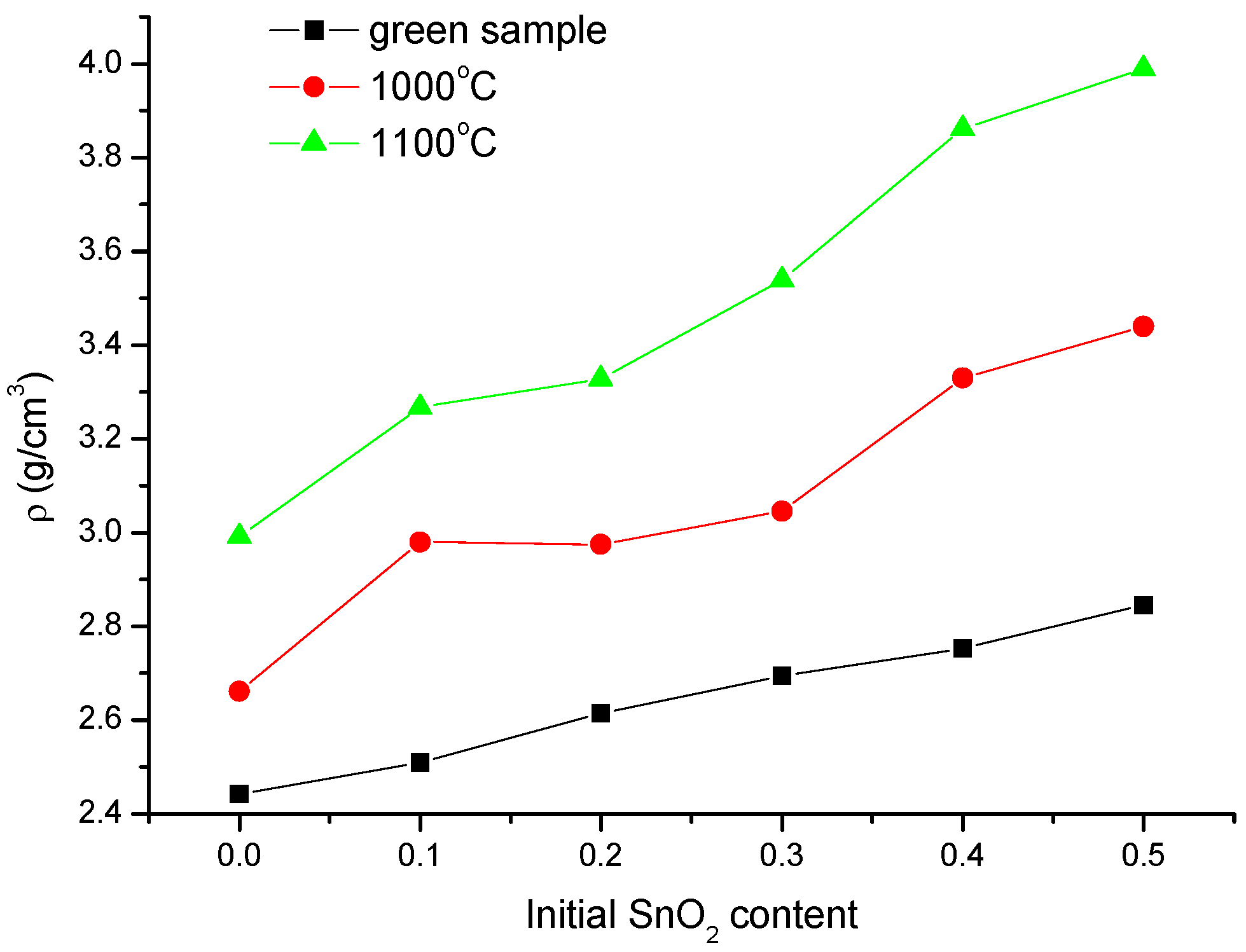
The change in average sample density with increase in SnO2 content is shown in Figure 2 for both sintering temperatures (1000 and 1100 °C). The theoretical density of MgO, α-Fe2O3 and SnO2 is 3.6, 4.51 and 6.95 g/cm3, respectively. As the added amount of SnO2 increases the green density is higher as expected. However, the density curves for sintered samples do not follow the same slope, with a more rapid increase for the initial small amount of SnO2 (10 wt.%) then a slightly slower increase, changing again for higher content of SnO2 (40 wt.%). All samples are porous, as we calculated that the achieved average density for magnesium ferrite sintered at 1000 and 1000 °C was 59 and 66.3% of the theoretical density. Similar can be expected for the compound samples.
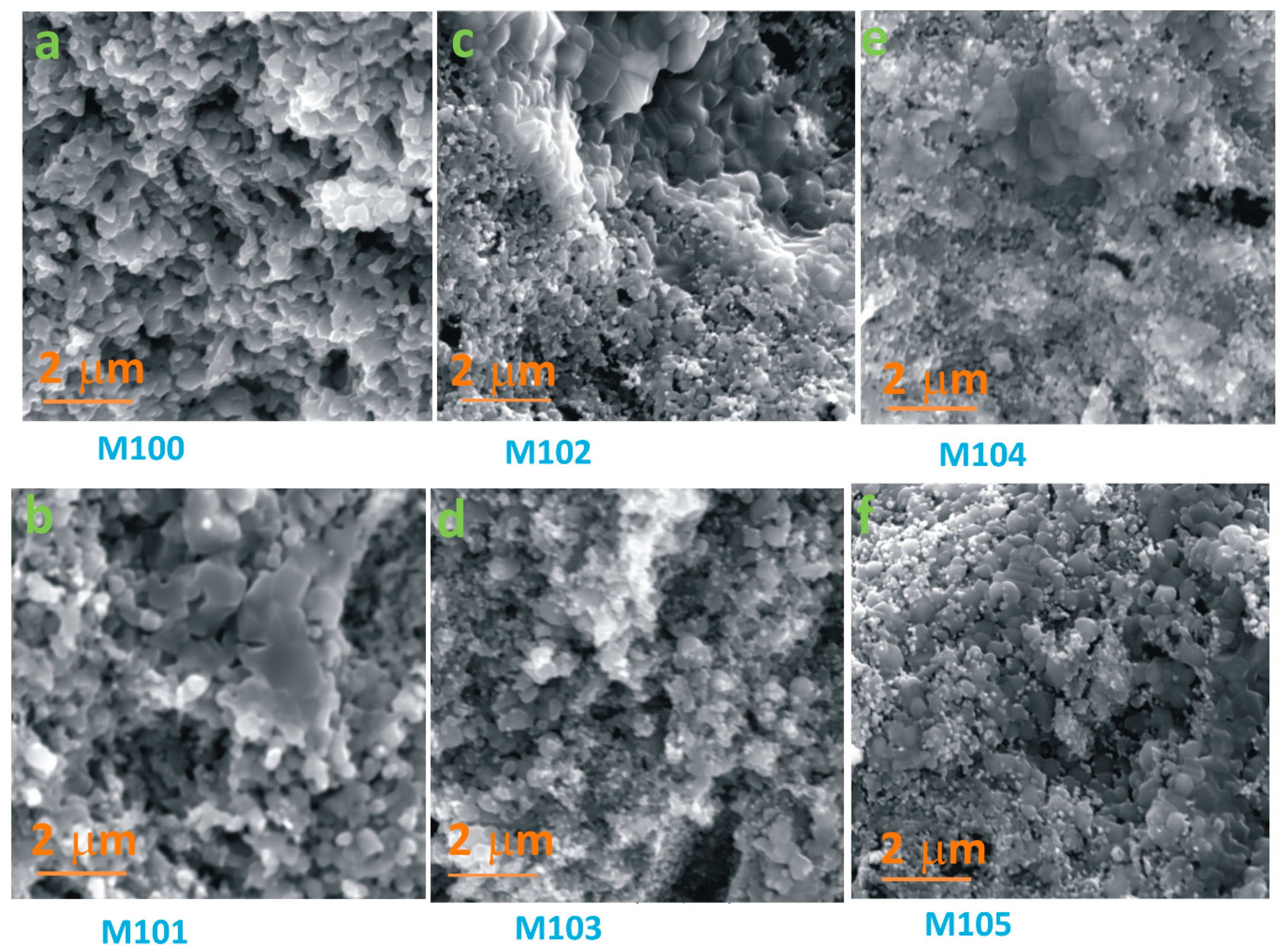
SEM images of freshly fractured samples sintered at 1000 °C with varying SnO2 content (M100–M105) are shown in Figure 3. It is noticeable that a porous structure was obtained, as indicated by the determined sample density.
A relatively homogenous porous structure was obtained for pure MgFe2O4 (M100), some grain growth is noticeable and there is no closed porosity (Figure 3a). When SnO2 is added to the starting powder mixture the resulting morphology is not homogenous and consists of parts with larger and parts with smaller particles (Figure 3b–f, samples M101–M105, respectively). In the sample with 10 wt.% SnO2 we can note parts with larger particles and parts with particles similar to the ones obtained for M100. It is obviously reflecting the influence of the presence of SnO2 and hematite (as determined by XRD, Figure 1). As the amount of added SnO2 increases (samples M102–M105, Figure 3c–f, with 20–50 wt.%SnO2) the morphology remains inhomogeneous but there is an increasingly greater number of smaller grains, the structure is noticeably porous and larger zones with smaller particles are intermingled with zones with larger particles.
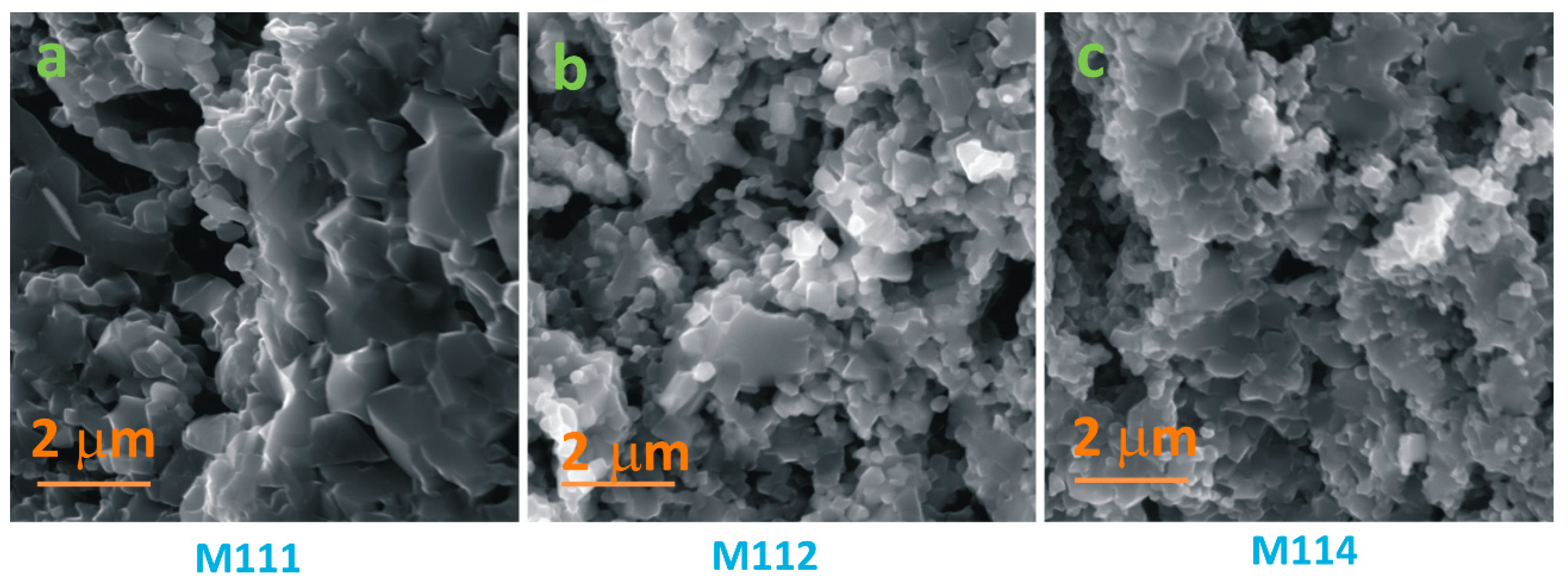
SEM images of samples M111, M112 and M114 sintered at 1100 °C are shown in Figure 4. At 1100 °C grain growth is noticeable, with advancement of the sintering process. Pores are still very noticeable and large between grains as seen for all three samples shown in Figure 4, though the sample density was higher (as shown in Figure 2). The sample morphology is still inhomogeneous, representing a mixture of small and larger particles. If we compare the morphology of samples M111 (Figure 4a), M112 (Figure 4b) and M114 (Figure 4c) it is noticeable that the overall particle size is lower for M112 and M114 compared to M111.
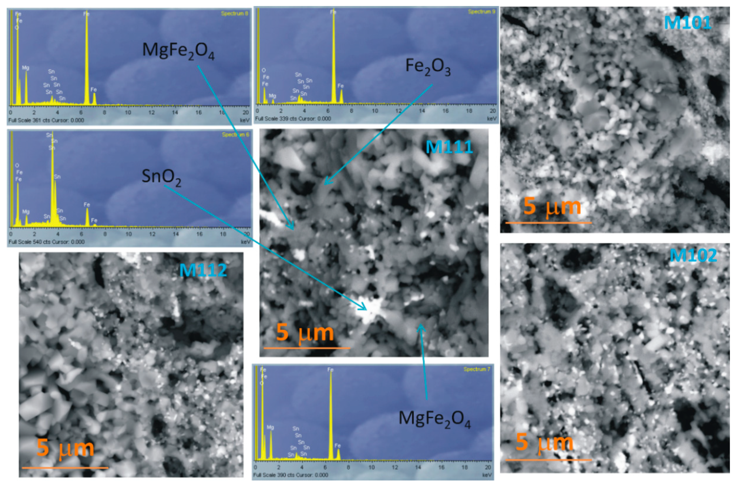
BSE images of samples M111, M112, M101 and M102 are shown in Figure 5. EDS analysis of some characteristic grains in sample M111 are also shown in Figure 5.
In the BSE mode larger atoms create a higher signal. In this case the Sn cation would be lighter in the image as it is heavier (molecular weight 118.71 g/mol) twice than Fe (56.935 g/mol) cations or almost four times than Mg (27.983 g/mol) cations. In all four shown images (Figure 5) we can note lighter, almost white smaller particles, among also on average smaller particles than in parts that are darker. EDS analysis showed that these white particles are SnO2, while the darker ones are MgFe2O4 or hematite. A distinct relatively large hematite grain has been marked the SEM image of sample M111 shown in Figure 5.

3.2. Impedance Analysis

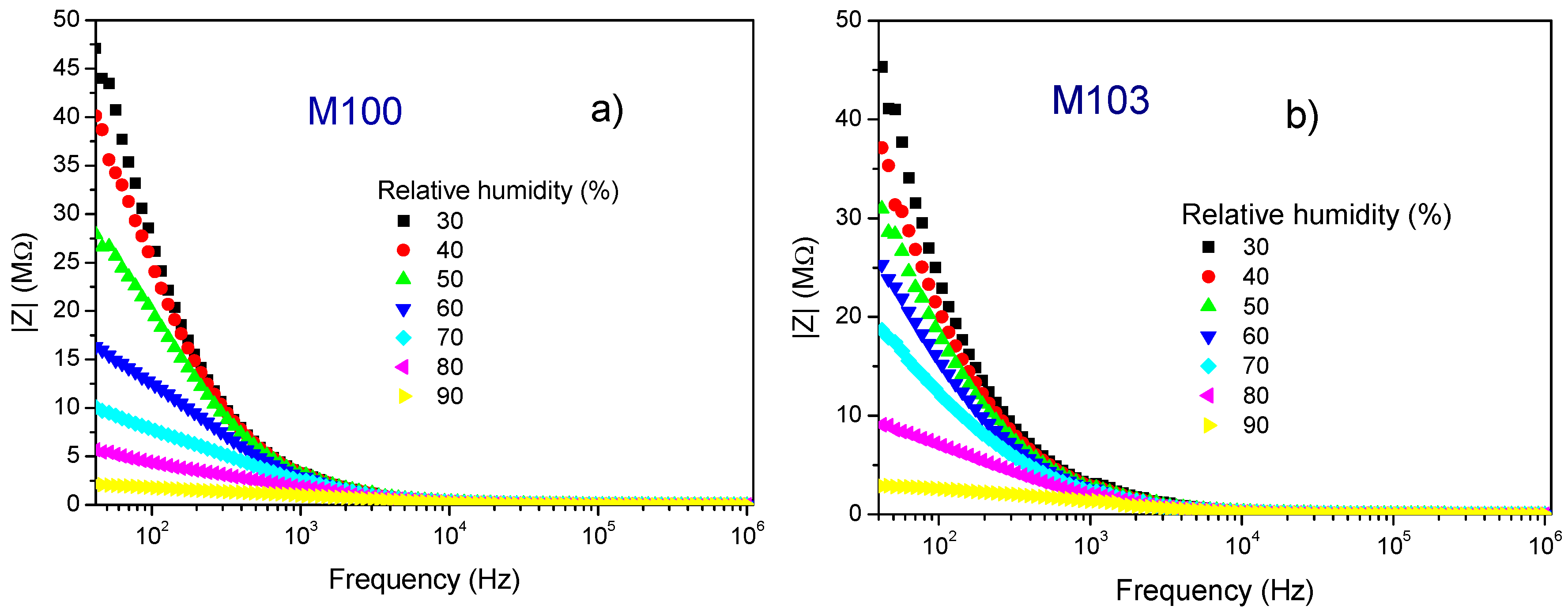
In resistive type sensing materials the resistance or impedance decrease as the amount of gas that interacts with its surface increases and this is the physical parameter that is monitored. In this case we monitored the change in impedance with change in the amount of relative humidity. Figure 6 shows the change in impedance measured for samples M100 (a) and M103 (b) as an example how the measured impedance changed with increase in relative humidity in the measured frequency range 42–1 MHz. As the relative humidity increased, the decrease in humidity was noticeable, especially in the lower frequency range. The measured complex impedance of all analyzed samples decreased with increase in frequency and it followed a similar trend for all investigated samples.
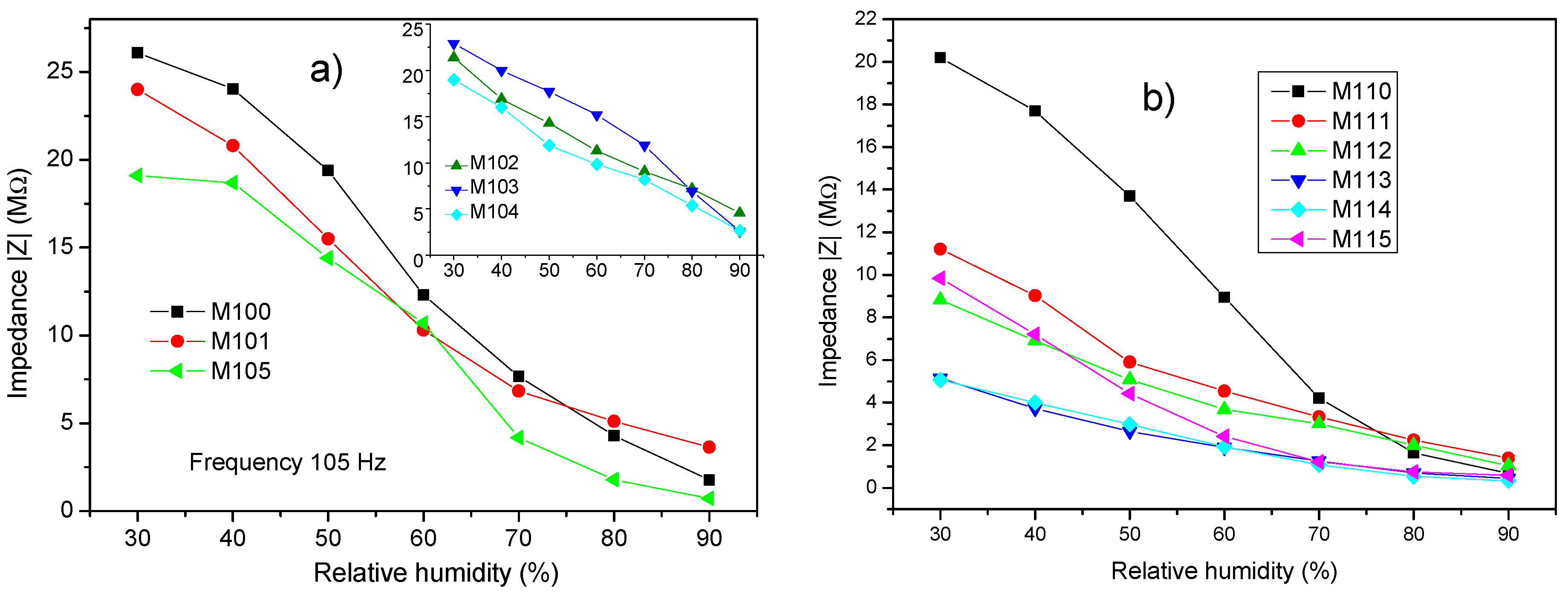
In Figure 7a we show how the impedance changed with increase in relative humidity (RH) for samples M100–105 sintered at 1000 °C, frequency 105 Hz. At low RH the measured impedance is lower in the samples containing more SnO2. As RH increases the impedance of the pure MgFe2O4 sample (M100) reduces considerably, from 26.1 MΩ for RH 30% to 1.77 MΩ for RH 90% that is almost 15 times. Addition of SnO2 (sample M101) reduced the impedance slightly at low RH and it changes in a similar way as M100, until very high RH when the impedance reduction is slightly lower, probably due to the difference in microstructure (as shown in Figure 3), resulting in an overall impedance reduction from 24.04 MΩ for RH 30% to 3.64 MΩ for RH 90%, that is ~7 times. Increase in SnO2 in the composition for samples M102–104 shows a relatively similar and almost linear reduction with increase in RH, with the impedance decreasing from 21.4, 22.9 and 19 MΩ at RH 30% to 4.57, 2.57 and 2.68 MΩ at RH 90%, that is ~5, 9 and 7 times. For M105 with the highest SnO2 content we can also note the highest reduction between RH 40–70% and similar to sample M101 a slightly lesser reduction slope for highest RH 80 and 90%, with the measured impedance decreasing from 19.1 MΩ at RH 30% to 0.725 MΩ at RH 90%, that is ~26 times.
The sensitivity of these analyzed compounds in the RH range 30–90% was calculated as S = ΔZRH. This represents the ratio between the change of sensor impedance and RH%, as described in Reference [19]. In Table 1 we show the determined values for samples M100–M105. We have made two estimations, in the RH30–90% and 40–90% intervals. The highest sensitivity was determined for sample M101 in the RH30–90% interval, showing that addition of SnO2 has improved sensitivity. The lowest error margin was obtained for samples M103 and 104, though their sensitivity was slightly lower and the lowest sensitivity and highest error margin for M105 with the most SnO2. If we start from RH 40, as this is often environment humidity (at least in our lab) then the highest sensitivity was obtained for the pure MgFe2O4 sample, though just a slightly lower value with a slightly lower error margin was obtained for M101 with the lowest amount of SnO2 added. However samples M102–104 still showed similar sensitivity and lower error margin.
In the case of samples sintered at 1100 °C the overall impedance values were lower, especially in samples with SnO2 making the reduction with increase in humidity lower as shown in Figure 7b, for samples M111–M115 measured at 105 Hz. This is connected with the grain growth due to higher sintering temperature, possibly also abnormal grain growth of hematite grains and overall inhomogeneous morphology. The sensitivity was also lower for all samples, with the highest value obtained for the pure MgFe2O4 sample (M110), both in the RH 30–90% and RH 40–90% ranges, as shown in Table 1.
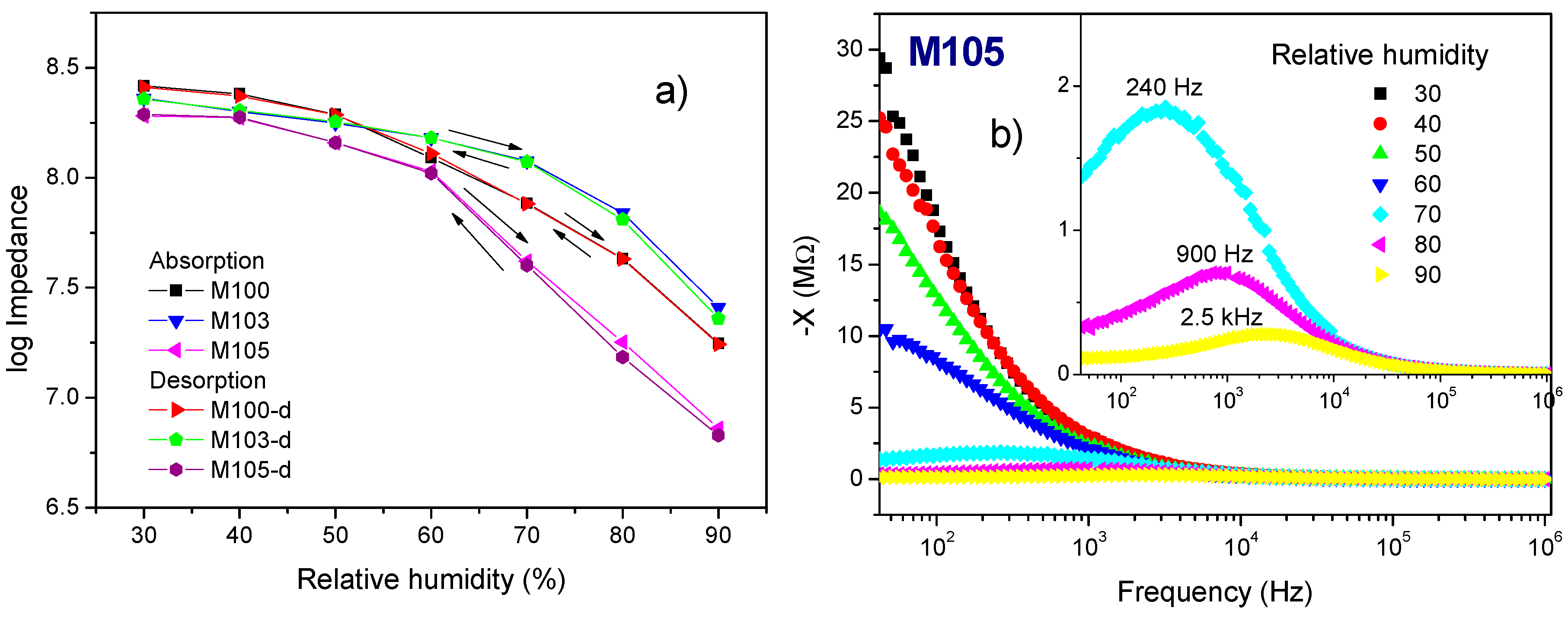
For a good sensing material the hysteresis denoting the time delay between absorption and desorption needs to be low. We measured the absorption with the RH going from 30–90% in steps of 10. Each value was read when the humidity in the chamber stabilized and this was usually around 30 min, After waiting another 30 min, the desorption values were measured in the same way decreasing the humidity in steps of 10 from RH 90% to 30%. At the frequency of 105 Hz we obtained a low values for all analyzed sensing compositions, below 3%, as shown in Figure 8a, for samples M100, M103 and M105.
The dependence of the imaginary part of impedance (−X) on frequency is shown in Figure 8b for sample M105. What is characteristic for the imaginary part of impedance for all analyzed samples is that with increase in relative humidity the relaxation peak shifts to higher frequency, especially for higher relative humidity values. In the case of sample M105 for RH 30–60% the relaxation peak is at relatively low frequencies, while at RH 70% it can be noted at ~240 Hz, increasing to ~900 Hz at RH 80% and ~2.5 kHz at RH 90%.
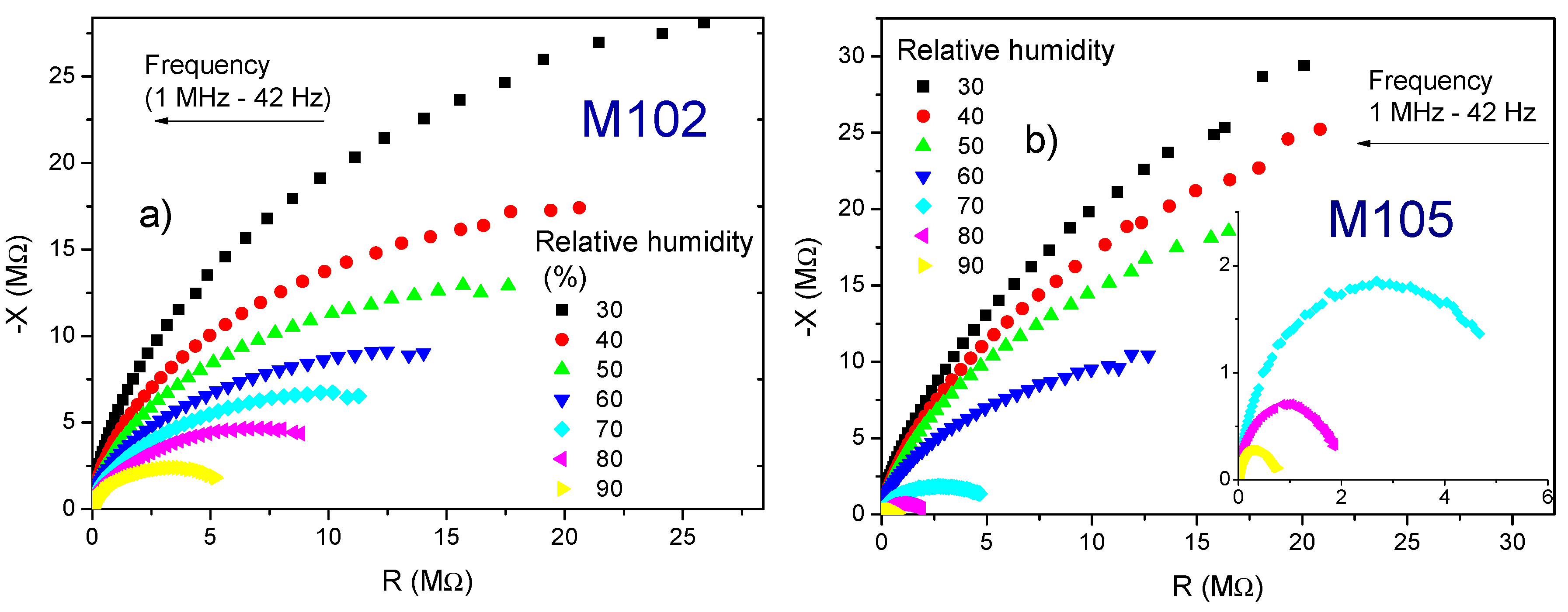
Cole-Cole diagrams obtained for samples M102 (a) and M105 (b) are shown in Figure 9. Cole-Cole diagrams of the electrical response can enable a better insight into the influence of change in relative humidity on the electrical response [1]. Similar diagrams were determined for the samples M100, M103 and M105. For high relative humidity the response is in the form of part of a semicircular arc, as can be observed for both samples. With increase in relative humidity these arcs change and shrink and resemble more of a complete semicircle. In the case of samples M100–M105 this change depends on the analyzed material composition and microstructure. Thus, we can note that for sample M102 (Figure 9a) this change is more uniform in the analyzed RH range 30–90%, while for M105 (Figure 9b) the decrease is much more rapid when RH is 70–90%. In both cases the semicircles are depressed.
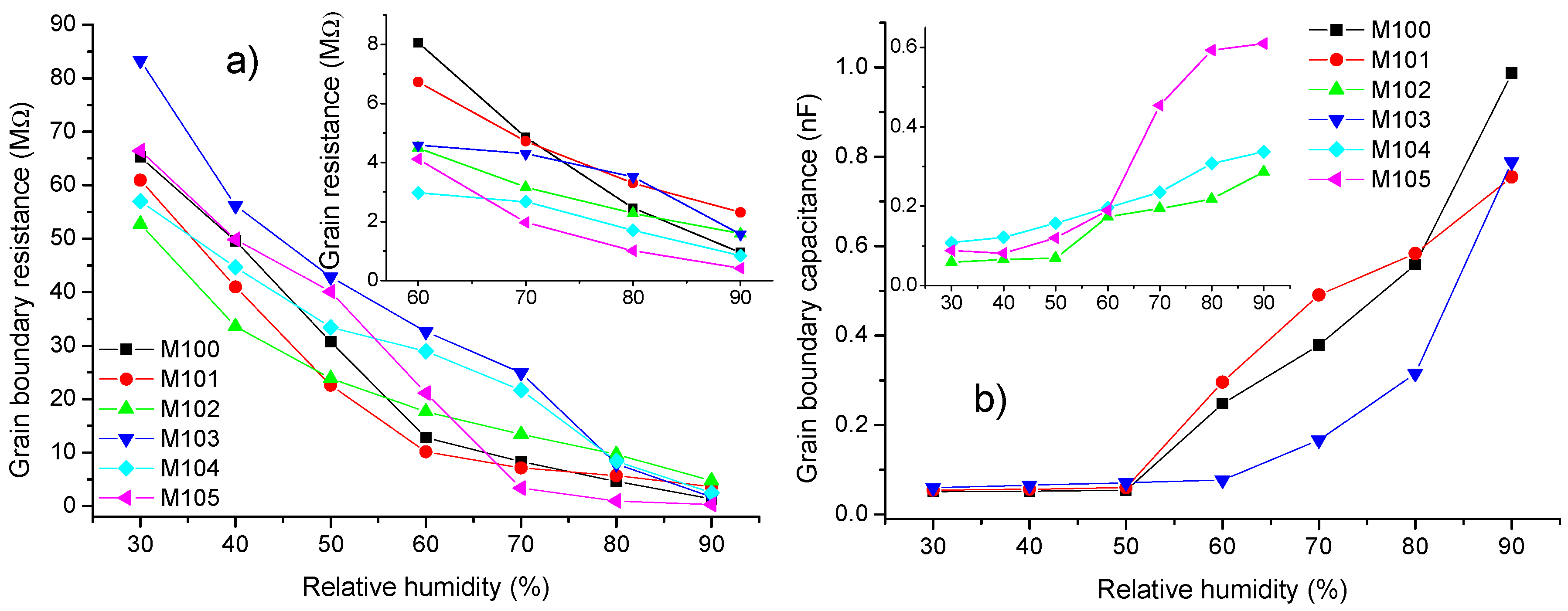
The measured complex impedance data was analyzed using equivalent circuits and the EIS Spectrum Analyzer software [20]. In the lower relative humidity range it was not possible to discern between the grain boundary and grain influence (modeled as parallel impedance/CPE element) and we assumed a dominant grain boundary influence, as has been the case before [21]. As the relative humidity increased (above 60%) the grain (bulk) component was more noticeable and the complex impedance data was modeled using a serial connection of two parallel impedance/CPE elements reflecting the influence of grain (bulk) and grain boundary components. The determined grain boundary resistance for samples M100–105 in the RH range 30–90% and the grain resistance in the RH 60–90% range decreases are shown in Figure 10a. The grain boundary resistance decreases almost linearly with increase in humidity from 83 MΩ determined for M103 at RH30% to 1.46 MΩ determined for M100 at RH90%. Similarly the grain resistance also shows a linear dependence and overall lower value with the highest determined for M100, RH 60% of 8 MΩ to the lowest determined for M105, RH 90% of 0.42 MΩ.
The grain boundary and grain capacitance were determined from the values obtained for the CPE element, using the formula described in detail in Reference [22]. Figure 10b shows the values obtained for grain boundary capacitance for samples M100–105 and we can see that they increase with increase in relative humidity and more rapidly for RH above 50% depending on the sample composition and microstructure. The determined grain resistance was overall lower and in the range 67–130 pF for samples M100–105 for RH 30–90%.

4. Discussion

Bulk MgFe2O4-Fe2O3-SnO2 compounds were obtained from starting nanopowders by sintering at 1000 and 1100 °C with varying SnO2 content (0–50 wt.%), denoted as M100–105 and M110–M115, respectively. Both sintering temperatures have been previously applied to obtain magnesium ferrite [1,9], so we aimed to determine which one would potentially yield better samples for humidity sensing. Reliable gas sensors need to fulfill the requirement of high sensitivity, fast response and good selectivity [2]. Oxide semiconducting materials have been both investigated and widely applied as gas sensing materials in commercial and industrial gas sensors. Advantages of oxide gas sensors also include its low cost, easy fabrication and these devices are simple to use. Their disadvantages include poor selectivity, low sensitivity and high power consumption due to the required often high operating temperature. This is the reason why heterostructures have been widely investigated [19]. Compounds (the simplest heterostructure) composed of two or more known good gas sensing materials could potentially address some of these issues.
Obtaining phase pure magnesium ferrite powder is difficult and often hematite and even magnesium oxide remain depending on the calcination temperature, though only hematite was noted at higher calcination temperatures, such as 900 and 1100 °C [23]. Rezlescu et al [9] noted that Sn4+ could also enter the MgFe2O4 lattice to a certain degree. Tin oxide has also been doped with Mg where up to 10 wt% Mg was incorporated into the SnO2 lattice, changing the peak intensity [24]. Hematite has been doped with Sn and up to 12 at% was incorporated into the hematite lattice resulting in a lattice distortion with cell volume increase [25]. As we started from MgO, α-Fe2O3 and SnO2 nanopowders that were mixed thoroughly and then sintered all these variations are possible and probable. Analysis of the measured XRD showed that we did not note any hematite impurity peaks in the samples with no added SnO2 and obtained phase pure MgFe2O4 at both applied sintering temperatures (samples M100 and M110, sintered at 1000 and 1100 °C, shown in Figure 1) However, with SnO2 addition hematite peaks can also be noted besides SnO2 peaks, as shown in Figure 1 for samples with the smallest amount of added SnO2 (10 wt.%, M101 and M111, sintered at 1000 and 1100 °C, respectively). The SnO2 peak intensity increased as expected with the increase in SnO2 content and we showed an example for sample M102 (20 wt.% SnO2). Thus, even though we obtained phase pure MgFe2O4 from starting nanopowders (MgO and Fe2O3), addition of SnO2 to the starting mixture resulted in the appearance of remaining hematite, besides SnO2. A more in depth analysis of this compound on powder samples could determine whether Mg has been incorporated in the SnO2 lattice, Sn in the hematite lattice and MgFe2O4, as determined in literature [23,24,25].
Our compound samples had a porous structure and the morphology changed with increase in SnO2 content and the sintering temperature (Figure 3, Figure 4 and Figure 5). The gas sensing mechanism of oxide semiconducting materials is linked to the sample surface, that when exposed to gases reacts with the gas molecules, making the microstructure of the gas sensing material of great significance. The SEM image of the pure MgFe2O4 sample (M100, Figure 3a) showed a porous microstructure with a relatively homogenous grain size. Similar morphologies have been obtained before for magnesium ferrite [1,16]. At 1000 °C addition of SnO2 resulted in an inhomogeneous morphology composed of parts with larger and parts with smaller particles, as shown in Figure 3b–f for samples with different SnO2 content (M101–M105). Rezlescu et al [9] noted that incorporation of Sn into magnesium ferrite resulted in a substantial decrease in grain size and significant reduction of electrical resistivity with increase in relative humidity. In this work the solid state synthesis procedure we applied using starting nanopowders resulted in a mixture of larger hematite and magnesium ferrite grains mixed with smaller tin oxide ones, confirmed by analysis of BSE images and EDS analysis of characteristic grains and particles noted (Figure 5). Smaller amounts of SnO2 improved the morphology for gas sensing by improving sensitivity, though the largest decrease of impedance with increase in RH was obtained for sample M105, with the highest amount of SnO2 with a morphology consisting of a mixture of larger magnesium ferrite and hematite particles mixed with many small tin-oxide particles.
In the case of humidity sensing the humidity sensing mechanism is based on chemisorption (low relative humidity) and physisorption of water vapor on the surface of the sensing material [1,11,13]. At higher relative humidity with the formation of several physisorbed layers hopping of H+ via water molecules occurs by the Grotthus mechanism [1,14,15]. At 1000 °C all samples showed a noticeable decrease in impedance with increase in relative humidity (Figure 5 and Figure 6a) but differing due to the differences in microstructure. Thus, the decrease in impedance with increase in relative humidity was almost linear for samples M102, M103 and M104, as shown in the inset on Figure 7a, with the impedance decreasing 5–9 times. The decrease of impedance for pure MgFe2O4, became more rapid with increasing RH. Addition of SnO2 reduced the impedance at lower RH, for sample M101 for which we determined the highest sensitivity. Even though the decrease in impedance for low RH was relatively small for M105 with the highest amount of tin oxide, it became much more rapid for RH 40–70% and also 80–90%, resulting in the overall decrease of impedance with RH of ~26 times. Changes in the slope of resistivity-humidity curves have been observed before when MgFe2O4 was doped with Sn and Mo [9]. This shows that further fine tuning of the microstructure by changing synthesis parameters, composition and synthesis method could lead to even better humidity sensing properties. The higher sintering temperature (1100 °C) resulted in grain growth. The sample density increased and though still porous, as the sintering process advanced leading to lower complex impedance and smaller change with humidity. The influence of humidity on complex impedance was higher at lower frequencies, as noted before for magnesium ferrite and other oxides [1,14,21]. The highest sensitivity was obtained for the sample with a small amount of SnO2 sintered at 1000 °C showing that this compound has potential for application in humidity sensing. This was confirmed by low hysteresis values obtained for this compound that is one of the requirements of a good sensing material [13].
The influence of change in relative humidity can be analyzed by following the change in the imaginary part of complex impedance in the analyzed frequency range. We noted a shift in the relaxation peak to higher frequency with increase in relative humidity, as shown in Figure 8b, for sample M105. This has been noted before for MgFe2O4 [1] and can be attributed to increasing relaxation time due to increase in ionic diffusion [26].
The determined Cole-Cole plots of complex impedance resembled diagrams obtained before for other oxide semiconducting materials [14,21]. As the relative humidity decreases the arc resembles more of a semicircle and shrinks. This is due to the humidity sensing mechanisms of these materials, as explained in the introduction and in more detail in References [14,21]. We can note that depending on the material composition and microstructure the semicircular arc or semicircle change and shrink slightly less or more rapidly. As observed before, the semicircles and semicircular arcs were depressed, indicating non-ideal Debye behavior as described in detail in Reference [22]. In this case a CPE element is used to replace capacitance and model this behavior. Analysis of complex impedance data using an equivalent circuit showed dominant influence of grain boundaries at low relative humidity, while the influence of the grain (bulk) component could be analyzed at higher relative humidity.

5. Conclusions

In this work we analyzed the humidity dependent response of MgFe2O4-Fe2O3-SnO2 bulk compound samples with varying SnO2 content sintered at 1000 and 1100 °C in view of application as a humidity sensing material. Addition of 10 wt.% of SnO2 combined with sintering at 1000 °C resulted in an inhomogeneous morphology and highest sensitivity of 0.391 MΩ/%RH at 105 Hz in the relative humidity range 30–90% at room temperature (25 °C). The highest decrease of impedance ~26 times for RH 30–90% was noted at 105 Hz for the sample with the highest amount of SnO2 sintered at 1000 °C. Further research will focus on fine tuning the composition and analyzing thick and thin films of this material to investigate response, recovery, stability, repeatability and selectivity for sensing humidity and other oxidizing and reducing gases.

Author Contributions

M.V.N. conceived the study, synthesized samples, performed SEM and EDS analysis, interpreted data and drafted the manuscript, M.D.L. synthesized samples, measured XRD and impedance in humidity chamber and critically revised the manuscript. Both authors agree to be accountable for all aspects of the work in ensuring that questions related to the accuracy or integrity of any part of the work are appropriately investigated and resolved. All authors have read and agreed to the published version of the manuscript.

Funding

This work was financed by the Ministry for Education, Science and Technological Development of the Republic of Serbia with the Contract with the Institute for Multidisciplinary Research, University of Belgrade 451-03-68/2020-14/200053

Conflicts of Interest

The authors declare no conflict of interest. The funders had no role in the design of the study; in the collection, analyses or interpretation of data; in the writing of the manuscript or in the decision to publish the results.

References

  1. Shah, J.; Kotnala, R. Humidity sensing exclusively by physisorption of water vapors on magnesium ferrite. Sens. Actuators B Chem. 2012, 171, 832–837. [Google Scholar] [CrossRef]
  2. Mirzaei, A.; Hashemi, B.; Janghorban, K. α-Fe2O3 based nanomaterials as gas sensors. J. Mater. Sci. Mater. Electron. 2015, 27, 3109–3144. [Google Scholar] [CrossRef]
  3. Ponce, M.A.; Bueno, P.R.; Varela, J.; Castro, M.; Aldao, C.M. Impedance spectroscopy analysis of SnO2 thick-films gas sensors. J. Mater. Sci. Mater. Electron. 2007, 19, 1169–1175. [Google Scholar] [CrossRef]
  4. Parthibavarman, M.; Hariharan, V.; Sekar, C. High-sensitivity humidity sensor based on SnO2 nanoparticles synthesized by microwave irradiation method. Mater. Sci. Eng. C 2011, 31, 840–844. [Google Scholar] [CrossRef]
  5. Malagù, C.; Carotta, M.; Giberti, A.; Guidi, V.; Martinelli, G.; Ponce, M.A.; Castro, M.; Aldao, C.M. Two mechanisms of conduction in polycrystalline SnO2. Sens. Actuators B Chem. 2009, 136, 230–234. [Google Scholar] [CrossRef]
  6. Neri, G. First Fifty Years of Chemoresistive Gas Sensors. Chemosensors 2015, 3, 1–20. [Google Scholar] [CrossRef]
  7. Šutka, A.; Gross, K.A. Spinel ferrite oxide semiconductor gas sensors. Sens. Actuators B Chem. 2016, 222, 95–105. [Google Scholar] [CrossRef]
  8. Druc, A.; Borhan, A.; Diaconu, A.; Iordan, A.; Nedelcu, G.; Leontie, L.; Palamaru, M. How cobalt ions substitution changes the structure and dielectric properties of magnesium ferrite? Ceram. Int. 2014, 40, 13573–13578. [Google Scholar] [CrossRef]
  9. Rezlescu, N.; Doroftei, C.; Rezlescu, E.; Popa, P. Structure and humidity sensitive electrical properties of the Sn4+ and/or Mo6+ substituted Mg ferrite. Sens. Actuators B Chem. 2006, 115, 589–595. [Google Scholar] [CrossRef]
  10. Petrila, I.; Tudorache, F. Humidity sensor applicative material based on copper-zinc-tungsten spinel ferrite. Mater. Lett. 2013, 108, 129–133. [Google Scholar] [CrossRef]
  11. Kotnala, R.; Shah, J.; Singh, B.; Kishan, H.; Singh, S.; Dhawan, S.; Sengupta, A. Humidity response of Li-substituted magnesium ferrite. Sens. Actuators B Chem. 2008, 129, 909–914. [Google Scholar] [CrossRef]
  12. Jeseentharani, V.; Reginamary, L.; Jeyaraj, B.; Dayalan, A.; Nagaraja, K.S. Nanocrystalline spinel NixCu0.8-xZn0.2Fe2O4: A novel material for humidity sensing. J. Mater. Sci. 2012, 47, 3529–3534. [Google Scholar] [CrossRef]
  13. Shah, J.; Kotnala, R.; Singh, B.; Kishan, H. Microstructure-dependent humidity sensitivity of porous MgFe2O4–CeO2 ceramic. Sens. Actuators B Chem. 2007, 128, 306–311. [Google Scholar] [CrossRef]
  14. Nikolic, M.V.; Lukovic, M.D.; Vasiljevic, Z.Z.; Labus, N.; Aleksić, O.S. Humidity sensing potential of Fe2TiO5—pseudobrookite. J. Mater. Sci. Mater. Electron. 2018, 29, 9227–9238. [Google Scholar] [CrossRef] [Green Version]
  15. Agmon, N. The Grotthus mechamism. Chem. Phys. Lett. 1995, 244, 456–462. [Google Scholar] [CrossRef]
  16. Shah, J.; Arora, M.; Purohit, L.; Kotnala, R.K. Significant increase in humidity sensing characteristics of praseodymium doped magnesium ferrite. Sens. Actuators A Phys. 2011, 167, 332–337. [Google Scholar] [CrossRef]
  17. Rao, P.; Chikate, R.C.; Bhagwat, S. Highly responsive and stable Y 3+ doped NiMg–ferrite thick films as an efficient humidity sensor. New J. Chem. 2016, 40, 1720–1728. [Google Scholar] [CrossRef]
  18. Tudorache, F. Investigations on microstructure, electrical and magnetic properties of copper spinel ferrite with WO 3 addition for applications in the humidity sensors. Superlattices Microstruct. 2018, 116, 131–140. [Google Scholar] [CrossRef]
  19. Zappa, D.; Galstyan, V.; Kaur, N.; Arachchige, H.M.; Sisman, O.; Comini, E. Metal oxide -based heterostructures for gas sensors-A review. Anal. Chim. Acta 2018, 1–23. [Google Scholar] [CrossRef]
  20. Bondarenko, A.S.; Ragoisha, G. EIS Spectrum Analyzer. Available online: http://www.abc.chemistry.bsu.by (accessed on 25 November 2016).
  21. Nikolic, M.V.; Lukovic, M.D.; Labus, N.J. Influence of humidity on complex impedance and dielectric properties of iron manganite (FeMnO3). J. Mater. Sci. Mater. Electron. 2019, 30, 12399–12405. [Google Scholar] [CrossRef]
  22. Nikolic, M.V.; Sekulic, D.L.; Vasiljevic, Z.Z.; Lukovic, M.D.; Pavlovic, V.; Aleksic, O.S. Dielectric properties, complex impedance and electrical conductivity of Fe2TiO5 nanopowder compacts and bulk samples at elevated temperatures. J. Mater. Sci. Mater. Electron. 2016, 28, 4796–4806. [Google Scholar] [CrossRef] [Green Version]
  23. Mukherjee, K.; Bharti, D.; Majumder, S.B. Solution synthesis and kinetic analyses of the gas sensing characteristics of magnesium ferrite particles. Sens. Actuators B Chem. 2010, 146, 91–97. [Google Scholar] [CrossRef]
  24. Sabarilakshmi, M.; Janaki, K. Effect of Mg concentration on structural, optical and humidity sensing performance of SnO2 nanoparticles prepared by one step facile route. J. Mater. Sci. Mater. Electron. 2017, 28, 8101–8107. [Google Scholar] [CrossRef]
  25. Orlandi, M.; Mazzi, A.; Arban, G.; Bazzanella, N.; Rudatis, P.; Caramori, S.; Patel, N.; Fernandes, R.; Bignozzi, C.A.; Miotello, A. On the effect of Sn-doping in hematite anodes for oxygen evolution. Electrochim. Acta 2016, 214, 345–353. [Google Scholar] [CrossRef]
  26. Dutta, S.; Choudhary, R.N.P.; Sinha, P.K.; Thakur, A.K. Microstructural studies of (PbLa)(ZrTi)O3 ceramics using complex impedance spectroscopy. J. Appl. Phys. 2004, 96, 1607. [Google Scholar] [CrossRef]
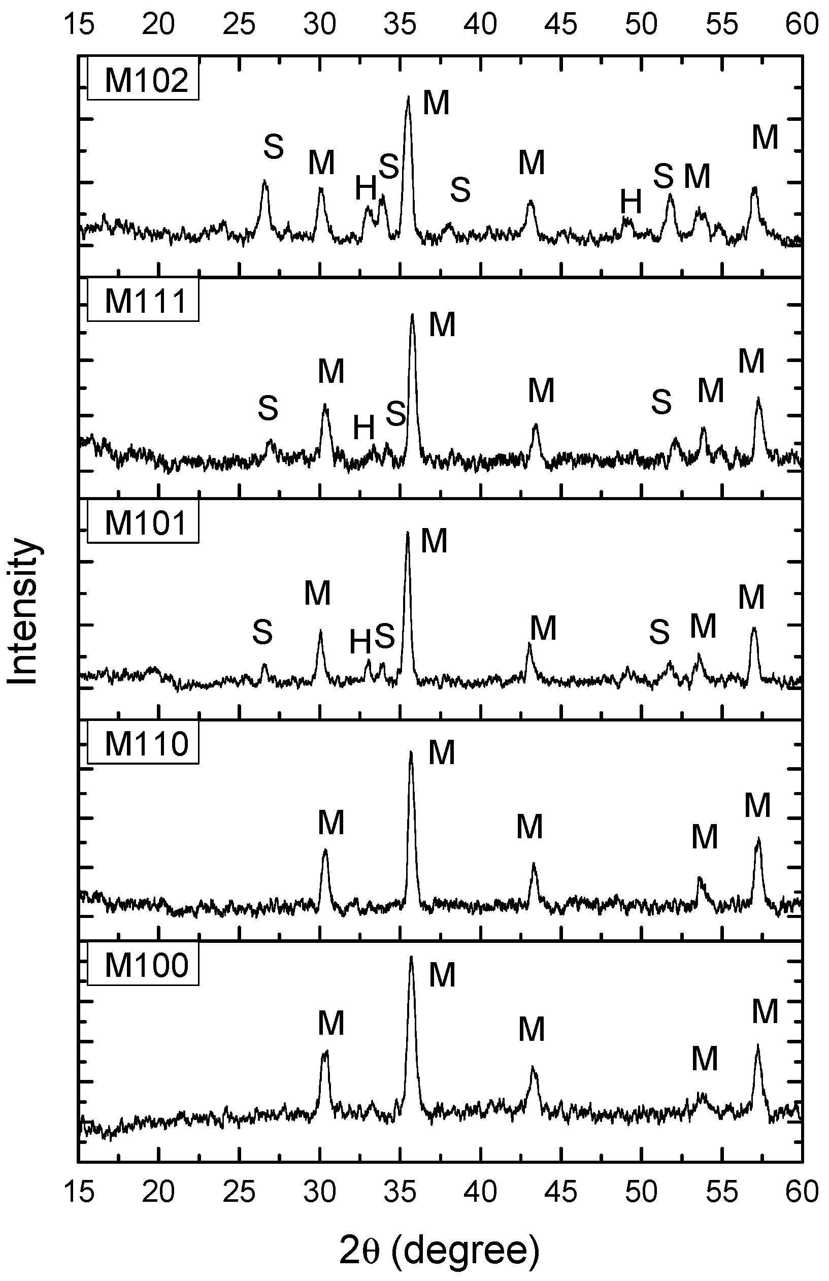
Figure 1. Characteristic parts of X-ray diffraction (XRD) patterns for samples M100, M101, M102, M110 and M111; M—MgFe2O4, S—SnO2, H—α-Fe2O3.
Chemosensors 08 00039 g001
Figure 2. Average sample density in relation to starting SnO2 content.
Chemosensors 08 00039 g002
Figure 3. Scanning electron microscopy (SEM) images of samples M100 (a), M101 (b), M102 (c), M103 (d), M104 (e) and M105 (f) recorded in SE mode.
Chemosensors 08 00039 g003
Figure 4. SEM images of samples M111 (a), M112 (b) and M114 (c) recorded in SE mode.
Chemosensors 08 00039 g004
Figure 5. SEM images of samples M101, M102, M111, M112 recorded in back scattering electron (BSE) mode and Electron dispersive X-ray spectroscopy (EDS) analysis of some characteristic grains in sample M111.
Chemosensors 08 00039 g005
Figure 6. Change of impedance of samples M100 (a) and M103 (b) with frequency in the relative humidity (RH) range 30–90%.
Chemosensors 08 00039 g006
Figure 7. Change of impedance for samples M100–M105 (a) and M110–115 (b) with relative humidity at 105 Hz.
Chemosensors 08 00039 g007
Figure 8. Absorption and desorption (hysteresis) curves obtained for M100, M103 and M105 samples at 105 Hz (a) and dependence of the imaginary part of complex impedance (−X) of sample M105 on frequency for RH 30–90% (b) inset: dependence of −X on frequency for RH 70, 80 and 90%.
Chemosensors 08 00039 g008
Figure 9. Complex impedance diagrams of samples M102 (a) and M105 (b) for RH 30–90%, inset in (b) shows complex impedance change for RH 70, 80% and 90%.
Chemosensors 08 00039 g009
Figure 10. Determined grain boundary and grain (inset) resistance (a) and grain boundary capacitance (b) for samples M100–105.
Chemosensors 08 00039 g010
Table 1. Sensitivity determined for samples M100–105 and M110–M115.
SampleRH 30–90% (MΩ/%RH)RH 40–90% (MΩ/%RH)
M1000.384 ± 0.0989 0.419 ± 0.0524
M1010.391 ± 0.05410.406 ± 0.0467
M1020.335 ± 0.06300.313 ± 0.0325
M1030.290 ± 0.03310.290 ± 0.0370
M1040.296 ± 0.03280.295 ± 0.0366
M1050.263 ± 0.11980.308 ± 0.0544
M1100.341 ± 0.05350.359 ± 0.0330
M1110.207 ± 0.03590.205 ± 0.0398
M1120.160 ± 0.02680.154 ± 0.0244
M1130.106 ± 0.02330.099 ± 0.0178
M1140.097 ± 0.01050.095 ± 0.0108
M1150.222 ± 0.04670.214 ± 0.0472